1
I
total
body
workout
8EARS
•
adjustable
resistance
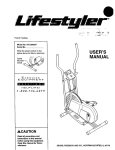
USER'S MANUAL
Model No. 831.287420
Serial No.
Write the serial number in the space
above for future reference.
Serial Number Decal
EXERCISE
E(:;_
U
I P
M
E
NT
HELPLINE!
1-800-736-6879
Patent Pending
SEARS, ROEBUCK
AND COo, HOFFMAN
ESTATE_,
I_ 1_017_1
TABLE OF CONTENTS
IMPORTANT PRECAUTIONS
..............................................................
BEFORE YOU BEGIN ...................................................................
ASSEMBLY
...........................................................................
ADJUSTMENT AND OPERATION ...........................................................
MAINTENANCE AND TROUBLE-SHOOTING
. ."................................................
CONDITIONING GUIDELINES .............................................................
PART LIST ...........................................................................
EXPLODED DRAWING .............................
".....................................
ORDERING REPLACEMENT PARTS ...............................................
WARRANTY ..........................................................
2
_ ........
2
3
3
6
8
9
10
11
.Back Cover
Back Cover
BEFORE YOU BEGIN
Thank you for selecting the innovative SEARS
LIFESTYLEFP CARDIO FORCE. The CARDIO FORCE
offers a unique form of low-impact exercise that uses
both the upper body and the lower body for increased
cardiovascular benefits and greater toning results.
For your benefit, read this manual carefully before
you use the CARDIO FORCE. If you have additional
questions, please call our toll-free HELPLINE at
1-800-736-6879, Monday through Saturday, 7 a.m.
until 7 p.m. Central Time (excluding holidays). To help
us assist you, please note the product model number
and serial number when calling. The model number is
831.287420. The serial number can be found on a
decal attached to the CARDIO FORCE (see the front
cover of this manual).
ASSEMBLY
Place all parts of the CARDIO FORCE in a cleared
area and remove the packing materials. Do not dispose of the packing matedals until assembly is completed. Read each step carefully before beginning.
PART CHART
Use the drawings below to identify the small parts
used in assembly. The number in parenthesis below
each drawing refers to the key number of the part. The
second number indicates the quantity needed for
assembly. Note: Some small parts may have been preattached for shipping purposes. If a part is not found in
the parts bag, check to see if it has been pre-attached.
THE FOLLOWING TOOLS (NOT INCLUDED) ARE
REQUIRED FOR ASSEMBLY:
• one phillips screwdriver
• one adjustable
• the included pedal tool (see the drawing below).
wrench
• one rubber mallet
Qq
3/4" x 2" Pedal Tool--1
1/2" Push Nut (30).--2
Note: Extra Push Nuts
may have been included.
1/2" Dome Cap (29)--4
Note: One extra Dome Cap
may have been included.
@
3/8" x 2 7/8" Carriage Bolt (35)--4
#6 x 3/8" Screw (16)--2
@8
3/8" Nylon Locknut (33)---4
1/4" x 2" Screw (17).--2
3
1. Find the Front Stabilizer (36), which has a decal on it.
Make sure that there is a Large Round Endcap (8) on
each end of the Front Stabilizer.
6
Attach the Front Stabilizer (36) to the Frame (6) with
two 3/8" x 2 7/8" Carriage Bolts (35) and 3/8" Nylon
Locknuts (33). Make sure that the indented holes in
the Front Stabilizer are turned toward the frame.
33
Attach the Rear Stabilizer (32) to the Frame (6) in the
same manner.
8
2. Plug the Sensor Wire (15) into the back of the Monitor
(1). Attach the Monitor to the bracket on the Frame (6)
with the two #6 x 3/8" Screws (16). Make sure that
the Sensor Wire is not pinched between the
Monitor and the Frame.
3. IMPORTANT NOTE: Before assembling the 1/2"
Dome Caps (29) in steps 3 and 4, be sun that all
parts are oriented as shown in the drawings. The
Dome Caps can be used only once; if the Dome
Caps must be removed, it will be necessary to
order new Dome Caps.
2
6
3
Make sure that there are two 1/2" Pivot Bushings (20)
in the indicated bracket on the Pedal Frame (7). Hold
the Pedal Frame so the bracket is between the holes
near the upper end of the Frame (6). Tap the 6" Pivot
Rod (21) through the Pedal Frame and the Frame. Tap
a 1/2" Dome Cap (29) onto each end of the Pivot Rod.
4. Make sure that there is a 112"Link Arm Bushing (19)
in the end of each Link Arm (4) (see the inset drawing). Align the ends of the Link Arms with the indicated
bracket on the Pedal Frame (7). Insert the 1 3/4" Rod
(22) through the Link Arms and the bracket. Tap a 112"
Dome Cap (29) onto each end of the Rod.
4
4
22
5. Attach the Seat (3) to the Seat Tube (5) with the two
1/4" x 2" Screws (17). Be sure that the Seat is oriented
as shown.
3
6. Apply a small amount of grease to the two indicated
shafts of the Pedal Frame (7). Slide a Pedal (12) onto
the right shaft. Make sure that the Pedal is turned so the
plastic tube is facing the Pedal Frame, as shown. Using
the included pedal tool, tap a 1F2"Push Nut (30) onto the
end of the shaft. Be sure that the Push Nut is turned as
Plastic
shown in the inset drawing.
Attach the other Pedal (12) (not shown) to the left shaft
of the Pedal Frame (7) in the same manner.
Note: Extra 1/2" Push Nuts (30) may have been included. Save the Push Nuts and the pedal tool in case
replacement Push Nuts are needed in the future.
7.
Before using the CARDIO FORCE, check the Magnet
(18) and the Reed Switch (15), Pivot the Pedal Frame
(7) until the Magnet is aligned with the Reed Switch
(see the inset drawing). Loosen the indicated #8 x 3/4"
Screw (27). Adjust the position of the Reed Switch so
that there is a 1/8" gap between the Magnet and the
Reed Switch. Retighten the Screw.
Make sure that all parts of the CARDIO FORCE are
propedy tightened.
5
t2
Pedal
Tool
ADJUSTMENT
AND OPERATION
Place the CARDIO FORCE on a level surface. Keep
the electronic monitor out of direct sunlight, or the display may be damaged. It is recommended that the
floor underneath the CARDIO FORCE be covered for
HOW TO OPERATE THE MONITOR
Note: If there is a thin sheet of clear film on the front of
the monitor, remove it before operating the monitor.
protection in case of slight oil leakage.
To turn on the power, press the on/off button or the
1.
DESCRIPTION
OF THE MONITOR MODES
on/reset button, or simply begin exemising. The
entire display will appear for two seconds. The
monitor will then be ready for operation.
The CARDIO FORCE features one of the two monitors
shown below. Both monitors have exactly the same
modes. The modes are described below:
2. Select one of the five modes:
1
Scan mode--When the power is tumed on, the
scan mode will be selected automatically. One
mode indicator will show that the scan mode has
been selected, and a second mode indicatorwill show
which mode is currentlydisplayed. The scan mode
can also be selected by pressing the mode button.
Mode Indicators\
s.eEo
I."'11.--i.I.--i
-I
11_
I
Speed, time, distance or calories mode--These
MODE
[
2
ON/OFF
I[
modes can be selected by repeatedly pressing the
mode button. The mode indicators will show which
mode has been seJected. (Make sure that the scan
mode is not selected.) The modes will be selected
in the following order:, speed, time, distance, calories.
]
Mode Indicators\
3. To reset the display, press the on/off button twice if
you have monitor 1, or the on/reset button if you have
monitor 2.
C-1!2-I.!-I
"1
e Eo
112
I
,
DISTANCE
CALORIE
MODE
I
SCAN
DN/REBET
][
- AUTO
!
- O FF -
To turn off the power, press the on/off button if you
have monitor 1, or simply wait for four minutes if
you have monitor 2. Both monitors have auto-off
features, If the pedals are not moved and the
monitor buttons are not pressed for about four
minutes, the power will turn off automatically.
EXERCISING ON THE CARDIO FORCE
Speed--Displays
your speed, in repetitions per minute.
Sit on the seat, place your feet on the pedals and hold
the handlebar. To add variety to your exemise, you can
place your hands close together or far apart, or hold
the handlebar with an overhand or underhand grip.
Time--Displays the length of time you have exemised.
Note: If you stop exemising for ten seconds or longer,
the time mode will pause until you resume.
Distance---Displays the total number of repetitions you
have completed, up to 999 or 9,999. The display will
then reset to zero and continue counting.
To begin exercising, pull the handlebar towards your
waist while pushing the pedals away with your legs.
Return to the starting position. This completes one
repetition. Repeat, moving with a smooth, continuous
motion. Move through the full range of motion, maintain a steady pace, and keep your back straight.
Calodes_Displays
the approximate number of
Calories you have burned. Note: If the resistance is on
the highest or lowest setting, the actual number of
Calories you have burned will be slightly higher or
lower than the number displayed.
ABDOMINAL
EXERCISE
To exercise your abdominal muscles, keep your arms
straight and bend back at the waist as you exercise.
Remember to keep your back straight.
Scan--Displays the speed, time, distance and calories
modes, for about 5 seconds each, in a repeating cycle.
R
RESISTANCE
ADJUSTMENT
I/I
Resistance Adjustment
Collar
To vary the intensity of your exercise, the resistance of
the CARDIO FORCE can be changed. There are 9
resistance levels: level 1 is the easiest, and level 9 is
the most difficult. To change the resistance, turn the
resistance adjustment collar on the Resistance
Cylinder (9). The arrow on the Resistance Cylinder will
show which resistance level you have selected.
CAUTION: The Resistance Cylinder becomes very
hot during use. Allow the Resistance Cylinder to
cool before touching it.
_--------_----_//T-/i//,l
d- - _
'/'_1_///'//
7
IA
Rej'_2SlaenCnt
Collar
MAINTENANCE
AND TROUBLE-SHOOTING
MONITOR CARE
Tighten all parts of the CARDIO FORCE regulady. The CARDIO FORCE can be cleaned with a soft, damp cloth.
Do not allow liquid to come in contact with the monitor. Keep the monitor out of direct sunlight or the LCD display may be damaged.
REPLACING THE BA'n'ERIES
A
If the display of the Monitor (1) becomes dim, the two
Ll154 watch batteries should be replaced. See drawing A.
Remove the upper #6 x 3/8" Screw (16) from the back of the
Monitor (1). See drawing B. Pivot the Pedal Frame (7) as
shown. Remove the lower #6 x 3/8" Screw (16) from the
back of the Monitor. Remove the Sensor Wire (15) from the
back of the Monitor. See the inset drawing. Remove the four
screws from the back cover of the Monitor and remove the
back cover. Push the two old batteries out of the clips, being
sure to note which way each battery is turned. Insert two
new batteries.
Reattach the back cover of the Monitor (1). Plug the Sensor
Wire (15) into the back of the Monitor. insert any excess
wire into the Frame (6). Reattach the Monitor to t.he Frame
with the two #6 x 3/8" Screws (16).
ADJUSTING THE MAGNET AND REED SWITCH
if the monitor does not function properly, the Magnet (18) and
Reed Switch (15) should be checked. Pivot the Pedal Frame
(7) until the Magnet is aligned with the Reed Switch. Loosen
the #8 x 3/8" Screw (27) and adjust the position of the Reed
Switch so that there is a 1/8" gap between the Magnet and
the Reed Switch. Retighten the Screw.
LuBRIcATING
THE CARDIO FORCE
The CARDIO FORCE should be oiled every six months in
the locations shown at the right. Apply a few drops of light
multi-purpose oil between each of the indicated dome caps
and the frame. Be sure to apply oil to each side of the CARDIO FORCE.
8
18
CONDITIONING GUIDELINES
The following guidelines will help you to plan your
exercise program. Remember that proper nutrition and
adequate rest are essential for successful results.
EXERCISE
INTENSITY
To maximize the benefits of exemising, it is important
to exemise with the proper intensity. The proper intensity level can be found by using your heart rate as a
guide. For effective aerobic exercise, your heart rate
should be maintained at a level between 70% and
85% of your maximum heart rate as you exercise.
This is known as your training zone. You can find your
training zone in the table below. Training zones are
listed for both unconditioned and conditioned persons
according to age.
UNCONDITIONED
TRAINING ZONE
AGE
(BEATS/MIN)
CONDITIONED
TRAINING ZONE
(BEATS/MIN)
20
138-167
133-162
25
136-166
132-160
30
135-164
130-158
35
134-162
129-156
40
132-161
127-155
45
131-159
125-153
50
129-156
124-150
55
127-155
122-149
60
126-153
121-147
65
125-151
119-145
70
123-150
118-144
75
122-147
117-142
80
120-146
115-140
85
118-144
114-139
Dudng the first few months of your exercise program,
keep your heart rate near the low end of your training
zone as you exercise. After a few months, your heart
rate can be increased gradually until it is near the middle of your training zone as you exercise.
To measure
your heart
rate, stop
exercising and
place two fingers on your
wrist. Take a
six-second
heartbeat
count, and
multiply the
result by 10 to find your heart rate. For example, if
your six-second heartbeat count is 14, your heart rate
is 140 beats per minute. (A six-second count is used
because your heart rate will drop rapidly when you
stop exercising.) Adjust the intensity of your exercise
until your heart rate is at the proper level.
WORKOUT GUIDELINES
A well-rounded workout should include the following
three phases:
A warm-up phase, lasting 5 to 10 minutes. Begin with
slow, controlled stretches, and progress to more rhythmic stretches to increase the body temperature, heart
rate and circulation in preparation for strenuous exercise. Stretching also guards against muscle, tendon
and ligament sprains.
A cardiovascular phase, including 20-30 minutes of
exercising with your heart rate in your training zone.
A cool-down phase, consisting of 5-10 minutes of
stretching. Thorough stretching offsets muscle contractions and other problems caused when you stop
exercising suddenly. Stretching for increased flexibility
is often most effective dudng this phase. This phase
should leave you relaxed and comfortably tired.
After a few months of regular exercise, you may complete up to five workouts each week, if desired.
Remember, the key to success is make exercise a
regular and enjoyable pad of your everyday life.
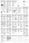
PART LISTAModel
Key
No.
Part
No.
Qty.
1
2
124883
126512
1
1
3
4
5
6
7
8
9
10
11
12
13
14
15
16
17
18
19
20
126013
126510
127158
NSP
127157
109416
123216
117545
117544
124807
126025
102308
124434
100244
013498
113349
103677
110576
1
2
1
1
1
4
1
2
2
2
2
2
1
2
2
1
4
4
No. 831.287420
R0996A
Key
No.
Part
No.
Qty.
Description
Monitor
Handlebar
21
22
127277
127137
2
2
6" Pivot Rod
1 3/4" Rod
Seat
Unk Arm
Seat Tube
Frame
Pedal Frame
Large Round Endcap
Resistance Cylinder
1 1/4" Round Endcap
I 1/2" x 2" Endcap
Pedal
1" x 2" Endcap
#8 x 1/2" Screw
Reed Switch/Sensor Wire
#6 x 3/8" Screw
1/4" x 2" Screw
Magnet/Retainer
1/2" LinkArm Bushing
1/2" Pivot Bushing
23
24
25
26
27
28
29
30
31
32
33
34
35
36
#
#
126517
126519
123131
125436
013300
127779
103903
127781
127138
127748
012149
t25022
120622
127786
126516
125453
2
4
2
1
1
2
8*
2*
1 •
1
4
2
4
1
1
1
1/2" Cylinder Bushing Set
3/4" Spacer
1" Bushing
1/2" x 3 1/4" Rod
#8 x 3/4" Screw
Handlebar Foam Grip
1/2" Dome Cap
1/2" Push Nut
1/2" x 4" Rod
Rear Stabilizer
3/8" Nylon Locknut
Hahdlebar Endcap
3/8" x 2 718" Bolt
Front Stabilizer
Users Manua[
3/4" x 2" Pedal Tool
Description
*Note: One extra 1/2" Dome Cap and extra 1/2"
Push Nuts may have been included.
Note: "#" indicates a non-illustrated part. Specifications are subject to change without notice, See the back cover
of this manual for information about ordering replacement parts.
10
EXPLODED
DRAWINGmModel
NO. 831.287420
Ro995A
34
\.
14
3
I
2
\
16
T
34
29
11
17
9_
23_
8
33
6
I
>
32
12
11
IMPORTANT ASSEMBLY UPDATE
Please replace assembly step 7 on page S of the user's manual with the step
below,
7. Before using the CARDIO FORCE, check the Magnet (18) and the Reed Switch
(15). Pivot the Pedal Frame (7) until the Magnet is aligned with the Reed Switch
(see the inset drawing). Loosen the Indicated #8 x 3/4" Screw (2"/). Adjust the position of the Reed Switch so that there Is a 1/8" gap between the Magnet and the
Reed Switch. Retighten the Screw.
Make sure that all parts of the CARDIO FORCE are properlytightened.
7
\
18
7
15/
7
Pad No. 127795 R1005A@ 1995 Sears, Roebuck and Co.
i
III
IMPORTANT ASSEMBLY UPDATE
Please refer to assembly steps 3 and 7 on peges 4 and 5 of the USER'S MANUAl.
_
mmembly steps $ and 7 with Ule steps ehown below.
IMPORTAN_.Beforeas_bling
the 1/2" DomeCaps(29),be suremat al! pa_
are positioned _ Mtown inthe dnwvingL The Dome Caps oanbe used only
once; if they nmst be removed, it will be necessary to order new Oome Csps.
3. Tap a 1/2" Dome Cap (,_) onto one
endofthe6` Pk_t Rod('21).Insert
the end of me Rvot Rod _to the
inclicetedhole in the Frame (6).
Make sure there are two 1/2" Pivot
Bushings
(20)in the_KScated
bracket on the Pedal Frame (7). Hold
the Pedal Frame so the bracket Is
between the holes in the Frarne (6).
Insert the 6" Pivot Rod (21) through
the I_)t.
Ho_ a 1PZ's_w;er
_twe_
the bmd_t and U_e Frame.
Insertthe Pivot Rod Ihroughthe
spacer and 1heFrame. Tap a 1/2"
Dome Cap (2S) onto the end of the
Pivot Rod.
Note: The part number of the 1/2'
spacer is 109374.
7. Before using the CARDIO FORCE,
checktheReedS_tch (lS) andthe
Magnet(18)nearU_edghtPed_
(12).Pk'otthePedaZFrame(7) unb_
the Magnet is aligned with 1he Reed
Switch (see the inset drawing).
Loosen the indicated#8 x 3/4"
Screw
(27)._j_ mepos_)no_t_
Reed Switch so that there is a 1R"
gap between the Magnet _d the
Switch. R_ghten the Screw.
Make surethatall partsof the CAR010 FORCE are properlytightened.
\ 1!
Part No. 127795 R1095B O 1995 Seam, Roebuck and Co.
SF_,4RS
The model number and serial number of your SEARS LIFESTYLER •
CARDIO FORCE are listed on a decal attached to the frame. See
the front cover of this manual to find the location of the decal.
Model No. 831.287420
All replacement parts are available for immediate pumhase or
special order when you visit your nearest SEARS Service Center. To
request service or to order parts by telephone, call the toll-free numbers listed at the left.
QUESTIONS?
If you find that:,
• you need help assembling or
operating the CARDIO FORCE
When requesting help or service, or ordering parts, please be prepared to provide the following information:
• a part is missing
• or you need to schedule repair
service
• The NAME OF THE PRODUCT (SEARS LIFESTYLEFP CARDIO
FORCE)
cell our toll-free HELPLINE
• The MODEL NUMBER OF THE PRODUCT (831.287420)
1-800-736-6879
• The PART NUMBER OF THE PART (see page 10 of this manual)
Monday-Saturday,
7 am-7 pm
Central Time (excluding holidays)
• The DESCRIPTION.OF
THE PAR,T (see page 10 of this manual)
REPLACEMENT
PARTS
If parts become worn and need
to be replaced, call the following
toll-free number
1-800-FON-PART
(1-800-366-7278)
I
FULL 90 DAY WARRANTY
[
For 90 days from the date of purchase, if failure occurs due to defect in material or workmanship in this
SEARS CARDIO FIT EXERCISER, contact the nearestSEARS Service Center throughout the United
States and SEARS will repair or replace the CARDIO FIT EXERCISER, free of charge.
This warranty does not apply whe_ the CARDIO FIT EXERCISER is used commercially or for rental purposes.
This warranty gives you specific legal dghts, and you may also have other rights which vary from state
to state.
SEARS, ROEBUCK AND CO., DEPT. 81"PNA, HOFFMAN ESTATES, IL 60179
Part No.126516 R0995A © 1995 Sears, Roebuck and Co.
Printed in USA


![PLAS A O ]-OR](http://vs1.manualzilla.com/store/data/005852706_1-5db0b7ed584537f0e62af161fb124638-150x150.png)