1
PCI-DAS-TC
User’s Manual
Thermocouple Inputs
for PCI Bus
Revision 2, October, 2001
© Copyright 2001, Measurement Computing Corporation
LIFETIME WARRANTY
Every hardware product manufactured by Measurement Computing Corp. is warranted against defects in materials
or workmanship for the life of the product, to the original purchaser. Any products found to be defective will be
repaired or replaced promptly.
LIFETIME HARSH ENVIRONMENT WARRANTYTM
Any Measurement Computing Corp. product which is damaged due to misuse may be replaced for only 50% of the
current price. I/O boards face some harsh environments, some harsher than the boards are designed to withstand.
When that happens, just return the board with an order for its replacement at only 50% of the list price.
Measurement Computing Corp. does not need to profit from your misfortune. By the way, we will honor this
warranty for any other manufacture’s board that we have a replacement for!
30 DAY MONEY-BACK GUARANTEE
Any Measurement Computing Corp. product may be returned within 30 days of purchase for a full refund of the
price paid for the product being returned. If you are not satisfied, or chose the wrong product by mistake, you do not
have to keep it. Please call for a RMA number first. No credits or returns accepted without a copy of the original
invoice. Some software products are subject to a repackaging fee.
These warranties are in lieu of all other warranties, expressed or implied, including any implied warranty of
merchantability or fitness for a particular application. The remedies provided herein are the buyer’s sole and
exclusive remedies. Neither Measurement Computing Corp., nor its employees shall be liable for any direct or
indirect, special, incidental or consequential damage arising from the use of its products, even if Measurement
Computing Corp. has been notified in advance of the possibility of such damages.
MEGA-FIFO, the CIO prefix to data acquisition board model numbers, the PCM prefix to data acquisition board
model numbers, PCM-DAS08, PCM-D24C3, PCM-DAC02, PCM-COM422, PCM-COM485, PCM-DMM, PCMDAS16D/12, PCM-DAS16S/12, PCM-DAS16D/16, PCM-DAS16S/16, PCI-DAS6402/16, Universal Library,
InstaCal, Harsh Environment Warranty and Measurement Computing Corp. are registered trademarks of
Measurement Computing Corp.
IBM, PC, and PC/AT are trademarks of International Business Machines Corp. Windows is a trademark of
Microsoft Corp. All other trademarks are the property of their respective owners.
Information furnished by Measurement Computing Corp. is believed to be accurate and reliable. However, no
responsibility is assumed by Measurement Computing Corp. neither for its use; nor for any infringements of patents
or other rights of third parties, which may result from its use. No license is granted by implication or otherwise
under any patent or copyrights of Measurement Computing Corp.
All rights reserved. No part of this publication may be reproduced, stored in a retrieval system, or transmitted, in any
form by any means, electronic, mechanical, by photocopying, recording or otherwise without the prior written
permission of Measurement Computing Corp.
Notice
Measurement Computing Corp. does not authorize any Measurement Computing Corp. product
for use in life support systems and/or devices without the written approval of the President of
Measurement Computing Corp. Life support devices/systems are devices or systems which, a) are
intended for surgical implantation into the body, or b) support or sustain life and whose failure to
perform can be reasonably expected to result in injury. Measurement Computing Corp. products
are not designed with the components required, and are not subject to the testing required to
ensure a level of reliability suitable for the treatment and diagnosis of people.
HM PCI-DAS-TC.doc
TABLE OF CONTENTS
1.0 INTRODUCTION.................................................................................................................. 1
2.0 INSTALLATION ................................................................................................................... 1
2.1 PCI-DAS-TC HARDWARE INSTALLATION ............................................................................... 1
2.2 SOFTWARE INSTALLATION........................................................................................................ 1
2.3 EXTERNAL CONNECTIONS & THE CIO-STA-TC ..................................................................... 2
2.3.1 PCI-DAS-TC CONNECTOR PINOUT..................................................................................................... 2
2.3.2 CIO-STA-TC ............................................................................................................................................. 3
2.3.3 OPEN THERMOCOUPLE DETECTION................................................................................................. 3
3.0 PROGRAMMING & APPLICATIONS.............................................................................. 3
4.0 THEORY OF OPERATION................................................................................................. 3
4.1 ISOLATED ANALOG INPUTS ....................................................................................................... 3
4.2 PROCESSING AND CONTROL ..................................................................................................... 4
4.3 PROCESS FLOW.............................................................................................................................. 4
5.0 SELF-CALIBRATION.......................................................................................................... 5
6.0 REGISTER DESCRIPTION ................................................................................................ 6
6.1
6.2
6.3
6.4
6.5
PCI-DAS-TC REGISTER OVERVIEW ........................................................................................... 6
PCI LOCAL REGISTER MAP ......................................................................................................... 6
REGISTER MAP DETAILS............................................................................................................. 7
DUAL PORT RAM MEMORY MAP .............................................................................................. 8
DUAL-PORT RAM BIT DEFINITIONS ....................................................................................... 10
6.5.1
6.5.2
6.5.3
6.5.4
6.5.5
Configuration Region (DPRAM Address 300 hex - 31F hex) ................................................................. 10
Float Region (DPRAM Address 320 hex – 363 hex)............................................................................... 11
A/D Count Region (DPRAM Address 370 hex - 395 hex) ...................................................................... 11
AM188 Mailbox (DPRAM Address 3FE hex) ........................................................................................ 11
PC Mailbox (DPRAM Address 3FF hex) ................................................................................................ 11
6.6 COMMANDS FROM THE PC TO THE PCI-DAS-TC................................................................. 11
6.6.1
6.6.2
6.6.3
6.6.4
6.6.5
6.6.6
6.6.7
Modify Sampling Parameters................................................................................................................... 11
Modify One or More Channel Parameters ............................................................................................... 12
Read a Single Channel’s Temperature ..................................................................................................... 12
Read Multiple Channels’ Temperature .................................................................................................... 13
Read A/D Counts for All Channels.......................................................................................................... 13
Read the Firmware Version Number ....................................................................................................... 14
Read Voltages From All Channels........................................................................................................... 14
6.7 ERROR CODES FROM THE PCI-DAS-TC .................................................................................. 15
6.8 HOW TO READ FLOATING POINT TEMPERATURE.............................................................. 15
7.0 ELECTRICAL SPECIFICATIONS .................................................................................. 16
This page is blank..
1.0 INTRODUCTION
Thank you for purchasing a PCI-DAS-TC. This board incorporates the latest in microelectronics
technology. It is easy to use, powerful, and extremely accurate. The PCI-DAS-TC includes a screw
terminal board with an isothermal block and CJC sensor, and a C37FFS-5, five-foot shielded cable.
The PCI-DAS-TC is a 16-channel thermocouple/voltage input board for the PCI bus. The board accepts
seven different types of thermocouple input, J, K, E, T, R, S, and B. It’s digital output is scaled for
temperature in either degrees C or F. An onboard microprocessor handles all the control and math
functions including: CJC (Cold Junction Compensation), automatic gain and offset calibration, scaling
(voltage to temperature translation) and thermocouple linearization. This relieves the computer from
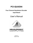
performing all these functions. The analog input section is electrically isolated from the computer. A
block diagram of the PCI-DAS-TC is shown below in Figure 1-1.
The PCI-DAS-TC works on the PCI bus. The PCI-DAS-TC is completely plug-and-play having no
jumpers or switches to set.
The PCI-DAS-TC is supported by Measurement Computing’s powerful Universal Library driver package.
The board is fully supported by SoftWIRE™ and other high-level data acquisition software.
2.0 INSTALLATION
2.1 PCI-DAS-TC HARDWARE INSTALLATION
1. Shut the computer OFF and open the case.
2. Locate an empty PCI expansion slot in your computer. Push the board firmly down into the expansion
bus connector. If it is not seated fully it may fail to work and could short circuit the PC bus power onto a
PC bus signal. This could damage the motherboard in your PC as well as the PCI-DAS-TC. Use the
screw provided on your computer's back plate to secure the board in it's location.
3. Plug one end of the cable provided into the board, and the other into the CIO-STA-TC.
4. Replace the cover to the computer and turn it ON. Your hardware is now installed.
2.2 SOFTWARE INSTALLATION
The simplest way to configure your board is to use the InstaCalTM program provided on the CD (or floppy
disk).
InstaCal will show you any available options, how to configure the various switches and jumpers (if
present) to match your application requirements, and will create a configuration file that your application
software (and the Universal Library) will refer to so the software you use will automatically have access
to the exact configuration of the board.
Please refer to the Software Installation Manual regarding the installation, testing, and operation of
InstaCal.
1
2.3 EXTERNAL CONNECTIONS & THE CIO-STA-TC
2.3.1 PCI-DAS-TC CONNECTOR PINOUT
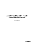
The PCI-DAS-TC uses a single 37-pin connector on the back plate to bring in 16 thermocouple channels,
CJC input, and ground. See Figure 2-1 below for the pinouts.
The PCI-DAS-TC is shipped with the CIO-STA-TC, a screw terminal board that provides an isothermal
block, a cold-junction sensor, and the C37FFS-5, a 5-foot shielded cable. A description of these items
follows.
1 ANALOG GROUND
2 Ch0 HI
3 Ch0 LO
4 Ch2 HI
5 Ch2 LO
6 Ch4 HI
7 Ch4 LO
8 Ch6 HI
9 Ch6 LO
10 Ch8 HI
11 Ch8 LO
12 Ch10 HI
13 Ch10 LO
14 Ch12 HI
15 Ch12 LO
16 ANALOG GROUND
17 Ch14 LO
18 Ch15 LO
19+15V ISOLATED VOLTAGE SOURCE
CJC INPUT 20
Ch1 HI 21
Ch1 LO 22
Ch3 HI 23
Ch3 LO 24
Ch5 HI 25
Ch5 LO 26
Ch7 HI 27
Ch7 LO 28
Ch9 HI 29
Ch9 LO 30
Ch11 HI 31
Ch11 LO 32
Ch13 HI 33
Ch13 LO 34
Ch14 HI 35
Ch15 HI 36
NONE 37
PCI-DAS-TC Connector Diagram
Figure 2-1. 37-Pin Board Connector
2
2.3.2 CIO-STA-TC
The CIO-STA-TC is a specially configured screw terminal adapter board designed specifically for use
with the PCI-DAS-TC. The board has screw terminals for each thermocouple channel, a cold junction
sensor integrated into an isothermal bar, and the option of installing an "open thermocouple detection"
circuit.
Each thermocouple input is made through two screw terminals (one + and one −). Connect the
thermocouple wires to the appropriate terminals, connect the CIO-STA-TC to the PCI-DAS-TC with the
shielded cable provided, and your board is ready for use.
NOTE: Be careful to observe correct polarity when connecting thermocouple wires or extension wires.
2.3.3 OPEN THERMOCOUPLE DETECTION
The only user configurable option in the CIO-STA-TC is the open thermocouple detection resistors.
These are a series of 20 MegOhm resistors that can be connected between the + terminal of the
thermocouple, and a known voltage that is larger than any allowable thermocouple output.
The 20 MegOhm resistors are large enough so that they do not affect the readings from the
thermocouples, but if a thermocouple junction should open, a 20 MegOhm will drive the input voltage
high enough, so the software can recognize that it is not a valid thermocouple reading.
Open thermocouple detection circuitry is set via dip switches on the CIO-STA-TC. DIP switches are
labeled, and each channel has a switch. To enable open thermocouple detection for a channel, set the
switch to ON (up, towards the isothermal block). To disable the function, set the switch to OFF (down,
towards the outside of the board). The unit is shipped with open thermocouple detection disabled.
3.0 PROGRAMMING & APPLICATIONS
The PCI-DAS-TC is supported by our Universal Library. We strongly recommend that you take
advantage of the Universal Library as your software interface.
The Universal Library provides complete access to board functions from a range of Windows
programming languages. If you are planning to write programs, or would like to run the example
programs for Visual Basic or any other language, please refer to the Universal Library manual.
4.0 THEORY OF OPERATION
4.1 ISOLATED ANALOG INPUTS
The analog input section of the PCI-DAS-TC consists of a CJC (Cold Junction Compensation) sensor
input, a 20 (differential) channel multiplexer, a precision 9.90V source, an analog ground source, a
programmable gain amplifier suitable for scaling the seven thermocouple types, and a high frequency,
synchronous V-F A/D converter. During normal operation, the V-F converts the CJC input, calibrates the
gain at a Gain = 1 using the 9.9V input, offset using the ground input, and measures the thermocouple or
voltage depending on the input type. The CJC and the gain/offset values are stored in an onboard RAM
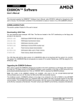
for cold junction scaling and calibration. These parameters are sampled continuously. See Figure 4-1
below.
The V-F converter is an Analog Devices AD652 SVFC (Synchronous V-F Converter) which offers full
scale frequency up to 2 MHz and extremely low linearity error. The 4 MHz clock for the V/F converter is
supplied by TIMER1 and passes through opto-isolation. The output of the V/F converter, passing back
3
through opto-isolation, is supplied to TIMER0. TIMER0 is gated on by TIMER2 for a period dependent
upon the specified conversion frequency of 50Hz, 60Hz or 400Hz. At the end of the sampling period, the
count in TIMER0 represents the voltage input. In general, the longer the count time, the higher the
resolution and better the noise reduction, unless in the case of periodic noise where the periodic frequency
(i.e. 50, 60, and 400 Hz) is more effective in reducing the noise.
4.2 PROCESSING AND CONTROL
This section consists of control and decode logic, a microcontroller and local memory to perform channel
scanning, CJC measurements, calibration, linearization, averaging, and voltage/temperature translation.
The above parameters are set up from a configuration file which is downloaded by the PC to the
microcontroller’s local memory through the Dual Port RAM. After the microcontroller is given the
command to start conversions, these parameters are set on a channel-by-channel basis with data reported
to the PC in the format specified by the configuration file. For thermocouple inputs, the microcontroller
reads the counter, adjusts the data based on the CJC value and gain/offset calibration, then linearizes and
converts the reading to the appropriate temperature units.
To perform linearization, the microcontroller gets the raw frequency count from TIMER0, translates that
into bits, factors in the CJC correction and gain/offset calibration, then refers to a previously stored
lookup table stored in ROM. There is a separate table for each thermocouple. The lookup tables are a
method to optimize the linearization by using more reference points along areas of greatest
temperature/voltage change instead of using mathematical translation, which requires lengthy polynomial
manipulation. Using lookup tables requires finding two consecutive points, one greater and one less than
the measured value, then interpolating the measured temperature value.
4.3 PROCESS FLOW
The PC itself performs very few functions for the PCI-DAS-TC. The DAS Wizard driver software
included with the PCI-DAS-TC board will set up individual channels, including the thermocouple type,
CJC on/off, voltage or thermocouple gain, channel, and temperature units. The sample rate and sample
averaging configuration are also set by the driver for all channels. Both during initialization and when the
configuration changes, this information is passed to the CPU through the Dual Port RAM and stored for
the specified channel. The PC then notifies the CPU to start taking measurements. When the CPU
completes a conversion, an interrupt is generated so that the PC reads the data from the Dual Port RAM
which the CPU had written to. The 32-bit floating point data is stored in four consecutive locations in the
Dual Port RAM. Refer to Section 6.4 for more details on this process.
4
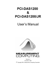
Figure 4-1. PCI-DAS-TC Block Diagram
The on-board CPU has a much more complicated task. The CPU must set all the parameters for
conversion of the selected channel. After conversion, it must get the data, adjust it based on the stored
CJC measurement, calibrate against gain/offset error, linearize it based on lookup tables for each
associated thermocouple type, and report the data to the PC through the Dual Port RAM. During this
process, the CPU goes to the next channel and sets up the parameters for that channel to allow suficient
settling time before the next conversion begins.
5.0 CALIBRATION
The PCI-DAS-TC is shipped fully-calibrated from the factory with calibration coefficients stored in
nonvolatile RAM. At run time, these calibration factors are loaded into system memory and automatically
retrieved each time a different range is specified.
5
6.0 REGISTER DESCRIPTION
We strongly urge users to take advantage of the Universal Library software package rather than attempt to
write register-level software for the PCI-DAS-TC. Register-level programming information is provided
here as a matter of completeness only. Register-level programming of this or any board is quite complex
and should only be attempted by an experienced programmer.
The PCI board provides two base address regions. The first, BADR1, provides access to the board's PLX
9052 PCI interface chip. This address also provides the interrupt control status and control registers for
the board. The second address (BADR2) performs the data and address reads and writes.
6.1 PCI-DAS-TC REGISTER OVERVIEW
Table 6-1 lists the registers and their functions.
Table 6-1. Register Functions
REGISTER
READ FUNCTION
WRITE FUNCTION
OPERATIONS
BADR1 + 4C hex
Interrupt Status
Interrupt Control
32-bit Dbl. Word
BADR2 + 0
N/A
Dual Port RAM Addr (LSBs)
8-bit Byte
BADR2 + 1
N/A
Dual Port RAM Addr (MSBs)
8-bit Byte
BADR2 + 2
Dual Port RAM Data Read
Dual Port RAM Data Write
8-bit Byte
BADR2 + 3
Interrupt status
N/A
8-bit Byte
BADR2 + 4
Resets microprocessor
Resets microprocessor
8-bit Byte
BADR2 + 5
N/A
DAS-TC Mode Register
8-bit Byte
6.2 PCI LOCAL REGISTER MAP
BADR1 + 4Ch: PLX9052 Interrupt Register: Read/Write
7
-
6
PCI_EN
5
-
4
-
3
-
2
INT
1
INTPOL
0
INTE
This register, as with all the 9052 registers, is 32-bits in length. Since the rest of the register has specific
control functions, they need to be masked off in order to access the interrupt control functions.
INTE
Local Interrupt Enable: 0 = disabled, 1 = enabled (default).
INTPOL
Interrupt Polarity: 0 = active low (default), 1 = active high.
INT
Interrupt Status: 0 = interrupt is not active, 1 = interrupt is active.
PCI_EN
PCI Interrupt Enable: 0 = disabled (default), 1 = enabled. This control signal allows
the interrupt to be passed to the PCI bus.
6
The PC de-asserts the interrupt by reading the mailbox location 3FF hex1 in the Dual Port RAM.
A detailed description of the registers and their functions is provided in the following section (6.3).
6.3 REGISTER MAP DETAILS
BADR2 + 0: Dual Port RAM Address Byte (LSB): Write Only
7
DPRA7
6
DPRA6
5
DPRA5
4
DPRA4
3
DPRA3
2
DPRA2
1
DPRA1
0
DPRA0
1
DPRA9
0
DPRA8
BADR2 + 1: Dual Port RAM Address Byte (MSB): Write Only
7
-
6
-
5
-
4
-
3
-
2
-
Select the location of the Dual Port RAM to be accessed by writing its address to BADR2 + 0 and
BADR2 + 1. The data from this location can be read by reading from BADR2 + 2 or data can be written
to this location by writing to BADR2 + 2.
BADR2 + 2: Dual Port RAM Data Byte: Read/Write
7
DPRD7
6
DPRD6
5
DPRD5
4
DPRD4
3
DPRD3
2
DPRD2
1
DPRD1
0
DPRD0
Data from the Dual Port RAM can be read by reading this register. Conversely, data can be written to
Dual Port RAM by writing to this location. The location of the Dual Port RAM is specified in register
BADR2 + 0 and BADR2 + 1.
BADR2 + 3: PC Interrupt Status Register: Read
7
INTR/
2
INTR/
3
INTL/
6
INTL/
5
-
4
-
3
-
2
-
1
-
0
-
This bit is 0 when the microcontroller writes to the PC’s mailbox location 3FF hex in
the Dual Port RAM. The PC can determine the cause of the interrupt and/or status and
simultaneously clear the INTR/ bit (i.e. make it 1) by reading mailbox location 3FF hex
in the Dual Port RAM.
This bit is 0 as soon as the PC writes to the microcontroller’s mailbox location 3FE hex
in the Dual Port RAM. This bit will be 1 after the microcontroller has read its mailbox.
The PC should only write to the microcontroller’s mailbox when this bit is 1.
BADR2 + 4: DASTC reset register: Read/Write
7
-
6
-
5
-
4
-
3
-
2
-
1
-
0
4
Reading or writing to this register resets the microcontroller on the PCI-DAS-TC .
1
Location 3FF hex is the mailbox for the right side of the DPRAM, which is indirectly connected to the PCI bus. Please refer to
the data sheets for the Cypress CY7C130 and Cypress application note “Understanding Asynchronous Dual-Port RAMs”.
2
This bit reflects the status of the INTR/ output of the Dual
Port RAM.
3
This bit reflects the status of the INTL/ output of the Dual
Port RAM.
7
BADR2 + 5: Mode select register : Write only
7
-
6
-
5
-
4
-
3
-
2
-
1
-
0
MODE
This register selects the mode of the PCI-DAS-TC on power-up. This register is read by the processor
only during power-up initialization.
MODE
This bit is 0 for normal operation mode. In normal mode, the board executes the
firmware. On power-up, this bit is cleared.
If this bit is set, the board is forced to download firmware via the Dual Port RAM and
program it into FLASH.
After toggling the MODE bit, reset the board by writing to BADR2 + 4 register,
because the processor reads the bit only during initialization.
6.4 DUAL PORT RAM MEMORY MAP
The PC and the AM188 processor in the PCI-DAS-TC board communicate and share data through a
1Kx8 dual-port RAM (DPRAM). The PC accesses the Dual Port RAM indirectly via registers at address
BADR2 + 0 through BADR2 + 2 as explained in the previous section. The AM188 processor, however,
accesses the Dual Port RAM directly.
The Dual Port RAM is divided into regions where predefined data is written by one processor and read by
the other. The top-most two bytes in the Dual Port RAM have special hardware logic associated with
them and serve as mailboxes. Byte 3FF hex is the PC’s mailbox and byte 3FE hex is the AM188’s
mailbox. When the PC writes to the AM188’s mailbox, it is notified about the arrival of data by the
assertion of the INTL/ signal. When the AM188 reads its mailbox this signal is de-asserted. Conversely,
when the AM188 writes to the PC’s mailbox, the PC is notified either via an interrupt or by the INTR/ bit
in register BADR2 + 3. When the PC reads its mailbox, this signal is de-asserted.
4
Moving the reset control from BADR2 + 3 to a separate register (BADR2 + 4) insures that the PCI-DAS-TC is not accidentally
reset.
8
Table 6-3. Dual Port RAM Memory Map
Addr
(Hex)
300
D7
D6
D5
-
-
310
311
*
*
31F
320
321
322
323
324
325
326
327
*
*
*
35C
35D
35E
35F
360
361
362
363
-
F1
F1
F0
F0
D7
D7
D7
D7
D7
D7
D7
D7
F1
D6
D6
D6
D6
D6
D6
D6
D6
F0
D5
D5
D5
D5
D5
D5
D5
D5
D7
D7
D7
D7
D7
D7
D7
D7
D6
D6
D6
D6
D6
D6
D6
D6
370
371
372
373
D7
D7
D7
D7
38E
38F
390
391
392
393
394
395
3FE
3FF
D4
D3
D2
AVG3 AVG2 AVG1 AVG0
D1
D0
Description of data
RS1
RS0
Configuration
Data
flow
to 188
TCT0 CH0 Configuration
TCT0 CH1 Configuration
*
*
TCT0 CH15 Configuration
D0
CH0 Float (Byte 0)
D0
CH0 Float (Byte 1)
D0
CH0 Float (Byte 2)
D0
CH0 Float (Byte 3)
D0
CH1 Float (Byte 0)
D0
CH1 Float (Byte 1)
D0
CH1 Float (Byte 2)
D0
CH1 Float (Byte 3)
*
*
*
D0
CH15 Float (Byte 0)
D0
CH15 Float (Byte 1)
D0
CH15 Float (Byte 2)
D0
CH15 Float (Byte 3)
D0
CJC Float (Byte 0)
D0
CJC Float (Byte 1)
D0
CJC Float (Byte 2)
D0
CJC Float (Byte 3)
to 188
to 188
*
*
to 188
to PC
to PC
to PC
to PC
to PC
to PC
to PC
to PC
*
*
*
to PC
to PC
to PC
to PC
to PC
to PC
to PC
to PC
G0
G0
TCT2
TCT2
TCT1
TCT1
G0
D3
D3
D3
D3
D3
D3
D3
D3
TCT2
D2
D2
D2
D2
D2
D2
D2
D2
TCT1
D1
D1
D1
D1
D1
D1
D1
D1
D5
D5
D5
D5
D5
D5
D5
D5
G1
G1
*
*
G1
D4
D4
D4
D4
D4
D4
D4
D4
*
*
*
D4
D4
D4
D4
D4
D4
D4
D4
D3
D3
D3
D3
D3
D3
D3
D3
D2
D2
D2
D2
D2
D2
D2
D2
D1
D1
D1
D1
D1
D1
D1
D1
D6
D6
D6
D6
D5
D5
D5
D5
D4
D4
D4
D4
D3
D3
D3
D3
D2
D2
D2
D2
D1
D1
D1
D1
D0
D0
D0
D0
CH0 count (Byte 0)
CH0 count (Byte 1)
CH1 count (Byte 0)
CH1 count (Byte 1)
to PC
to PC
to PC
to PC
D7
D7
D7
D7
D7
D7
D7
D7
D6
D6
D6
D6
D6
D6
D6
D6
D5
D5
D5
D5
D5
D5
D5
D5
D4
D4
D4
D4
D4
D4
D4
D4
D3
D3
D3
D3
D3
D3
D3
D3
D2
D2
D2
D2
D2
D2
D2
D2
D1
D1
D1
D1
D1
D1
D1
D1
D0
D0
D0
D0
D0
D0
D0
D0
CH15 count (Byte 0)
CH15 count (Byte 1)
0V count (Byte 0)
0V count (Byte 1)
9.9V count (Byte 0)
9.9V count (Byte 1)
CJC count (Byte 0)
CJC count (Byte 1)
to PC
to PC
to PC
to PC
to PC
to PC
to PC
to PC
D7
D7
D6
D6
D5
D5
D4
D4
D3
D3
D2
D2
D1
D1
D0
D0
AM188 Mailbox
PC Mailbox
to 188
to PC
9
6.5 DUAL-PORT RAM BIT DEFINITIONS
6.5.1 Configuration Region (DPRAM Address 300 hex - 31F hex)
These 32 bytes in the Dual Port RAM are used to set up and configure data acquisition parameters. The
configuration region specifies global parameters which affect all channels and parameters for each
individual channel. Section 6.6 describes the sequence of operations required to set the configuration.
DPRAM Address 300hex: Sampling Parameters
RS1:0
Resolution:
RS1
0
0
1
RS0
X
1
1
Resolution (Hz)
50
60
400
AVG3 to AVG0 The number of data values used in computing the moving average from each channel.
The microcontroller stores the values from each channel in a circular buffer whose size
is specified by AVG3 to AVG0. When a new sample is acquired, it is added to the
buffer overwriting the oldest sample and the moving average is computed. This number
must be between 0 and 15; the number of samples used to compute the average is one
more than this.
DPRAM Address 310 hex – 31F hex: Channel Parameters
This area sets the parameters for each individual channel:
F1:0
Temperature Format.
F1
0
0
1
G1:0
Format
Centigrade
Fahrenheit
Kelvin
Voltage Gain
G1
0
0
1
1
TCT2:0
F0
0
1
X
G0
0
1
0
1
Gain
1
125
166.7
400
Thermocouple Type
TCT2
0
0
0
0
1
1
1
1
TCT1
0
0
1
1
0
0
1
1
TCT0
0
1
0
1
0
1
0
1
Thermocouple Type
B
E
J
K
R
S
T
Not connected
10
6.5.2 Float Region (DPRAM Address 320 hex – 363 hex)
These bytes are used to store either the temperature or voltage from the channels. This region is divided
into four-byte blocks where each block has the data from a channel.
6.5.3 A/D Count Region (DPRAM Address 370 hex - 395 hex)
These bytes are used to store the average A/D count from the thermocouple channels, CJC channel and
the ground and 9.9V reference voltage on the board. This region is divided into two-byte blocks where
each block has the 16-bit count from a channel.
6.5.4 AM188 Mailbox (DPRAM Address 3FE hex)
This byte is used to send commands to the microcontroller in the PCI-DAS-TC. Please refer to Section
6.5 for details about the commands. When the PC writes to this location, bit INTL/ in BADR2 + 3 is
reset. After the microcontroller reads from this location, INTL/ goes high.
6.5.5 PC Mailbox (DPRAM Address 3FF hex)
This byte is used by the PCI-DAS-TC to convey information to the PC. When the microcontroller in the
PCI-DAS-TC writes to this location, bit INTR/ in BADR2 + 3 (see Section 6.3) becomes 0 and
simultaneously the interrupt is asserted. After the PC reads this location, INTR/ becomes 1 and the
interrupt is de-asserted.
6.6 COMMANDS FROM THE PC TO THE PCI-DAS-TC
This section describes the software commands between the PC and the PCI-DAS-TC. The commands
carry out the following operations.
•
Load a new configuration.
•
Read a single channel’s temperature.
•
Read multiple channels’ temperature.
•
Read the CJC temperature
•
Read version number of firmware.
6.6.1 Modify Sampling Parameters
•
The PC modifies one or more of the sampling parameters in byte 300 hex.
•
The PC writes the following command to the AM188 mailbox in the Dual Port RAM.
Addr
3FE
D7
1
D6
0
D5
0
D4
0
D3
0
D2
0
D1
0
D0
0
•
The PCI-DAS-TC reads, processes the new configuration and then writes a return code into the
PC mailbox in Dual Port RAM. This causes bit INTR/ in BADR2 + 3 to go low and an interrupt
(if any is selected) is asserted to the PC. The PC can either poll INTR/ or respond to the interrupt.
Note, that it may take some time for the PCI-DAS-TC to set the new sampling parameters and
start sampling.
•
When bit INTR/ in BADR2 + 3 is low, the PC reads the following return code from the PC
mailbox. Reading the mailbox causes INTR/ to go high and the interrupt to be de-asserted.
11
Addr
3FF
D7
1
D6
0
D5
0
D4
ERR4
D3
ERR3
D2
ERR2
D1
ERR1
D0
ERR0
Please refer to the return codes given in the next section.
6.6.2 Modify One or More Channel Parameters
•
The PC modifies one or more of the channel configuration bits in the configuration region of
Dual Port RAM (refer to section ).
•
The PC writes the following command to the AM188 mailbox in the Dual Port RAM.
Addr
3FE
D7
1
D6
0
D5
0
D4
0
D3
0
D2
0
D1
0
D0
1
•
The PCI-DAS-TC reads, processes the new configuration and then writes a return code into the
PC mailbox in Dual Port RAM. This causes bit INTR/ in BADR2 + 3 to go low and an interrupt
(if any is selected) is asserted to the PC. The PC can either poll INTR/ or respond to the interrupt.
•
When bit INTR/ in BADR2 + 3 is low, the PC reads the following return code from the PC
mailbox. Reading the mailbox causes INTR/ to go high and the interrupt to be de-asserted.
Addr
3FF
D7
1
D6
0
D5
0
D4
ERR4
D3
ERR3
D2
ERR2
D1
ERR1
D0
ERR0
Please refer to the return codes given in the next section.
6.6.3 Read a Single Channel’s Temperature
•
The PC writes the following command to the AM188 mailbox in the Dual Port RAM specifying
the channel to be read
Addr
3FE
D7
1
D6
0
D5
0
D4
1
D3
CHL3
D2
CHL2
D1
CHL1
D0
CHL0
where CHL3-CHL0 specify the channel number.
•
The PCI-DAS-TC writes the temperature into the specified channel’s 4-byte block and a return
code into the PC mailbox signifying that data is available in Dual Port RAM. This causes bit
INTR/ in BADR2 + 3 to go low and an interrupt (if enabled) is asserted to the PC. The PC can
either poll INTR/ or respond to the interrupt. Note that the CJC channel’s temperature in
Centigrade is simultaneously updated to bytes 360 hex-363 hex.
•
When bit INTR/ in BADR2 + 3 is low, the PC reads the following return code from the PC
mailbox. Reading the mailbox causes INTR/ to go high and the interrupt to be de-asserted.
Addr
3FF
D7
1
D6
0
D5
0
D4
ERR4
D3
ERR3
D2
ERR2
D1
ERR1
D0
ERR0
Please refer to the return codes given in the next section.
•
If there are no errors, the PC reads four bytes of data for the selected channel from the float
region of the Dual Port RAM.
12
6.6.4 Read Multiple Channels’ Temperature
•
The PC writes the following command to the AM188 mailbox in the Dual Port RAM specifying
the low channel number in the block of channels to be read
Addr
3FE
D7
1
D6
0
D5
1
D4
0
D3
CHL3
D2
CHL2
D1
CHL1
D0
CHL0
where CHL3-CHL0 specify the low channel number.
•
The PC polls bit INTL/ in BADR2 + 3 to go high. This bit will go high as soon as the
microcontroller has read its mailbox.
•
The PC writes the following command to the AM188 mailbox in the Dual Port RAM specifying
the high channel number in the block of channels to be read
Addr
3FE
D7
1
D6
0
D5
1
D4
1
D3
CHH3
D2
CHH2
D1
CHH1
D0
CHH0
where CHH3-CHH0 specify the high channel number.
•
The PCI-DAS-TC writes the temperature for the specified channels into the appropriate 4-byte
blocks in the float region of the Dual Port RAM. A return code is also written to the PC mailbox
signifying that data is available in Dual Port RAM. This causes bit INTR/ in BADR2 + 3 to go
low and an interrupt (if enabled) is asserted to the PC. The PC can either poll INTR/ or respond to
the interrupt. Note that the CJC channel’s temperature in Centigrade is simultaneously updated to
bytes 360 hex to 363 hex.
•
When bit INTR/ in BADR2 + 3 is low, the PC reads the following return code from the PC
mailbox. Reading the mailbox causes INTR/ to go high and the interrupt to be de-asserted.
Addr
3FF
D7
1
D6
0
D5
0
D4
ERR4
D3
ERR3
D2
ERR2
D1
ERR1
D0
ERR0
Please refer to the return codes given in the next section.
•
If there are no errors, the PC reads four bytes of data for each channel from the data region of the
Dual Port RAM. Note that the four bytes of data constitute a floating point value.
6.6.5 Read A/D Counts for All Channels
•
The PC writes the following command to the AM188 mailbox in the Dual Port RAM
Addr
3FE
D7
1
D6
1
D5
0
D4
0
D3
0
D2
0
D1
1
D0
0
•
The PCI-DAS-TC writes a return code into the PC mailbox in Dual Port RAM signifying that
data is available in Dual Port RAM. This causes bit INTR/ in BADR2 + 3 to go low and an
interrupt (if enabled) is asserted to the PC. The PC can either poll INTR/ or respond to the
interrupt.
•
When bit INTR/ in BADR2 + 3 is low, the PC reads the following return code from the PC
mailbox. Reading the mailbox causes INTR/ to go high and the interrupt to be de-asserted.
Addr
3FF
D7
1
D6
0
D5
0
D4
ERR4
D3
ERR3
D2
ERR2
Please refer to the return codes given in the next section.
13
D1
ERR1
D0
ERR0
•
If there are no errors, the PC reads two bytes of A/D count for each channel from the A/D count
region of the Dual Port RAM.
6.6.6 Read the Firmware Version Number
•
The PC writes the following command to the AM188 mailbox in the Dual Port RAM
Addr
3FE
D7
1
D6
1
D5
0
D4
0
D3
0
D2
0
D1
0
D0
0
•
The PCI-DAS-TC writes the firmware version number into the PC mailbox in Dual Port RAM.
This causes bit INTR/ in BADR2 + 3 to go low and an interrupt (if enabled) is asserted to the PC.
The PC can either poll INTR/ or respond to the interrupt.
•
When bit INTR/ in BADR2 + 3 is low, the PC reads the following value from the PC mailbox.
Reading the mailbox causes INTR/ to go high and the interrupt to be de-asserted.
Addr
3FF
D7
MAJ3
D6
MAJ2
D5
MAJ1
D4
MAJ0
D3
MIN3
D2
MIN2
D1
MIN1
D0
MIN0
Where MAJ3:0 is the major version number and MIN3:0 is the minor version number. There is
an implied decimal point between the major and minor version number.
6.6.7 Read Voltages From All Channels
•
The PC writes the following command to the AM188 mailbox in the Dual Port RAM
Addr
3FE
D7
1
D6
1
D5
0
D4
0
D3
0
D2
0
D1
1
D0
1
•
The PCI-DAS-TC writes the voltages of all 16 thermocouple channels and the CJC channel into
the float region of the Dual Port RAM and a return code into the PC mailbox signifying that data
is available. This causes bit INTR/ in BADR2 + 3 to go low and an interrupt (if enabled) is
asserted to the PC. The PC can either poll INTR/ or respond to the interrupt.
•
When bit INTR/ in BADR2 + 3 is low, the PC reads the following return code from the PC
mailbox. Reading the mailbox causes INTR/ to go high and the interrupt to be de-asserted.
Addr
3FF
D7
1
D6
0
D5
0
D4
ERR4
D3
ERR3
D2
ERR2
D1
ERR1
D0
ERR0
Please refer to the return codes given in the next section.
•
If there are no errors, the PC reads four bytes of data for each channel from the float region of the
Dual Port RAM. The readings are in volts.
14
6.7 ERROR CODES FROM THE PCI-DAS-TC
After the PCI-DAS-TC executes a command sent by the PC, it writes back a result code to the PC’s
mailbox. Table 6-3 lists the error codes and their description.
Table 6-3. Error Codes
Code in HEX
Description
80
Command executed successfully.
81
Sampling and channel parameters have not been loaded from the PC. This is the error code when
the PCI-DAS-TC is powered up.
82
Input voltage exceeds the chosen thermocouple’s range.
83
Low channel number is higher than the high channel number in a read command.
84
Unknown command.
85
Open thermocouple.
Note that the most significant bit of the error code is always ‘1’
6.8 HOW TO READ FLOATING POINT TEMPERATURE
Each channel’s temperature reading is stored as four bytes in the Dual Port RAM. The following program
listing illustrates how the PC can read a given channel’s temperature after issuing either the command to
read the temperature from a single channel or from multiple channels.
//Reads the Dual Port RAM and returns the specified channel's temperature.
//The DAS_TC must be sent the command to read one channel or a block of
//channels prior to reading the Dual Port RAM
//Params
nBaseAddr = base address of the board
//
nChan is the channel number to read.
float ReadChanTemp(int nBaseAddr, int nChan)
{
int nOffset; //offset into Dual Port RAM for the channels temp.
float fVal=0.0f; //reading which is in float
nOffset= 0x320 + nChan*sizeof(float);
//Read the 4 individual bytes which make up the float, starting from the
//lowest byte to the highest byte
BYTE *yTmp= (BYTE *)&fVal;
for (int nP=nOffset; nP<=nOffset+3; nP++, yTmp++)
*yTmp= ReadDRAM(nBaseAddr, nP);
return fVal;
}
//Reads a byte from the specified offset in the Dual Port RAM
//Params : nBaseAddr=Base address of the board
//
nOffset = byte offset into the Dual Port RAM
//Returns : Byte read
BYTE ReadDPRAM(int nBaseAddr, int nOffset)
{
//Write the low byte of the offset addr
_outp(nBaseAddr+REG_ADDR_LO, nOffset);
//Write the high byte of the offset addr
_outp(nBaseAddr+REG_ADDR_HI, (nOffset>>8));
//read the data register and return the byte
return (_inp(nBaseAddr+REG_DATA));
15
7.0 ELECTRICAL SPECIFICATIONS
Typical for 25°C unless otherwise specified.
Analog Input Section
A/D converter type
AD652 V/F Converter
Accuracy & Resolution (voltage measurements):
Gain
1
125
166.7
400
Range
−2.5 to 10V
−20 to 80mV
−15 to 60mV
−6.25 to 25mV
Accuracy (Worst Case)
±0.01% of reading ±2.5mV
±0.01% of reading ± 20µV
±0.01% of reading ± 15µV
±0.02% of reading ± 6.25µV
@ 50Hz
312.5µV
2.5µV
1.88µV
0.781µV
Resolution
@ 60Hz
375µV
3.0µV
2.25µV
0.938µV
@ 400Hz
2.5mV
20.0µV
15.0µV
6.25µV
Resolution
@ 60Hz
0.05 °C
0.05 °C
0.04 °C
0.04 °C
0.07 °C
0.08 °C
0.08 °C
@ 400Hz
0.40 °C
0.40°C
0.25 °C
0.25 °C
0.44 °C
0.52 °C
0.54 °C
Accuracy & Resolution (Thermocouple measurements, not including CJC errors):
Type
J
K
E
T
R
S
B
Range
0 to 750°C
−200 to 1250°C
−200 to 900°C
−270 to 350°C
0 to 1450°C
0 to 1450°C
0 to 1700°C
Accuracy (Worst Case)
±0.5 °C
±1.4 °C
±1.1 °C
±0.9 °C
±2.3 °C
±2.3 °C
±3.0 °C
@ 50Hz
0.05 °C
0.04 °C
0.03 °C
0.03 °C
0.06 °C
0.06 °C
0.07 °C
Number of Channels
Programmable Ranges
16 differential Thermocouple inputs, 1 CJC input
−2.5V to +10V, −20mV to +80mv, −15mV to +60mV,
−6.25mV to 25mV
Voltage Gains
Thermocouple Types
1, 125, 166.7, 400
J, K, E, T, R, S, B
A/D pacing
Continuous conversions, software-programmable for 50 Hz,
60 Hz, or 400 Hz
A/D Trigger Sources
Data Transfer
Software-triggered
Single I/O register transfer through Dual Port RAM
Conversion Rates (Integrating time)
50 Hz, 60 Hz, 400 Hz, software programmable
*Conversion Rates (per channel)
22.2 msec @ 50 Hz typical, 22.3 msec maximum
8.8 msec @ 60 Hz typical, 18.9 msec maximum
4.6 msec @ 400 Hz typical, 4.7 msec maximum
*This is the total time to convert the channel, process the data,
and provide a delay to switch the gain and channel.
Linearity Error (A/D specs)
Gain Drift (A/D specs)
Zero Drift (A/D specs)
Power Supply Rejection Ratio
Overvoltage Protection
CMRR @ 60Hz
Input Leakage Current
±0.05% @ 4 MHz clock
±75 ppm/°C max
±50uV/°C max
0.01 %/V
−40 to +55V
80dB minimum
±80 nA maximum
16
Input Impedance
Absolute Maximum Input Voltage
100 MegOhms minimum
−40V to +55V
Isolation to PC
500V min through DC/DC converter and opto-isolators
Miscellaneous
Averaging - Moving average, 1 to 16 samples, softwareselectable
Calibration - Calibration is performed with each channel scan
to remove offset and gain error. CJC channel is also measured
with each calibration.
Processor Reset - On power-up, watchdog timeout, or
software command. Processor boots within one second of
reset. Active low.
Watchdog timer - 1.6 seconds nominal. Processor generates
watchdog disable signal after boot-up.
Temperature units - Programmable for conversion to degrees
C or degrees F
Interrupts
Interrupt Enable
Interrupt Sources
2, 3, 4, 5, 6, or 7
Programmable
Dual Port RAM when the Processor Mailbox has data.
Crystal Oscillator
Frequency
Frequency Accuracy
32 MHz
100 ppm
CIO-STA-TC Adapter
CJC Type
Configuration
AD592CN
CJC centered in an iso-thermal block on which the screw
terminals have been mounted.
Channels
16 (plus CJC output)
Calibration Error
@ 25 °C
25°C to +105 °C
0.3°C typical,
0.5°C maximum
0.5°C typical, 1.0°C maximum
Linearity Error
−25°C to +105 °C
0.1°C typical, 0.35°C maximum
Temperature Coefficient
Long Term Stability
Open Thermocouple Detect
1µA/°C typical
0.1 °C / month
On/Off switch selectable for each channel, full scale reading
Power Consumption
+5V Operating
887 mA typical, 1441 mA maximum
Environmental
Operating Temperature Range
Storage Temperature Range
Humidity
0 to 50°C
−20 to 70°C
0 to 90% non-condensing
17
For Your Notes.
18
EC Declaration of Conformity
We, Measurement Computing Corporation, declare under sole responsibility that the product:
PCI-DAS-TC
ISA bus, thermocouple input board
Part Numbers
Description
to which this declaration relates, meets the essential requirements, is in conformity with, and CE marking
has been applied according to the relevant EC Directives listed below using the relevant section of the
following EC standards and other normative documents:
EU EMC Directive 89/336/EEC: Essential requirements relating to electromagnetic compatibility.
EU 55022 Class B: Limits and methods of measurements of radio interference characteristics of
information technology equipment.
EN 50082-1: EC generic immunity requirements.
IEC 801-2:
equipment.
Electrostatic discharge requirements for industrial process measurement and control
IEC 801-3: Radiated electromagnetic field requirements for industrial process measurements and control
equipment.
IEC 801-4: Electrically fast transients for industrial process measurement and control equipment.
Carl Haapaoja, Director of Quality Assurance
Measurement Computing Corporation
16 Commerce Boulevard,
Middleboro, Massachusetts 02346
(508) 946-5100
Fax: (508) 946-9500
E-mail: [email protected]
www.measurementcomputing.com