1
Am186 and Am188 Family
Instruction Set Manual
February, 1997
© 1997 Advanced Micro Devices, Inc.
Advanced Micro Devices reserves the right to make changes in its products
without notice in order to improve design or performance characteristics.
This publication neither states nor implies any warranty of any kind, including but not limited to implied warrants of merchantability or fitness for
a particular application. AMD assumes no responsibility for the use of any circuitry other than the circuitry in an AMD product.
The information in this publication is believed to be accurate in all respects at the time of publication, but is subject to change without notice. AMD
assumes no responsibility for any errors or omissions, and disclaims responsibility for any consequences resulting from the use of the
information included herein. Additionally, AMD assumes no responsibility for the functioning of undescribed features or parameters.
Trademarks
AMD, the AMD logo, and combinations thereof are trademarks of Advanced Micro Devices, Inc.
Am186, Am188, and E86 are trademarks of Advanced Micro Devices, Inc.
FusionE86 is a service mark of Advanced Micro Devices, Inc.
Product names used in this publication are for identification purposes only and may be trademarks of their respective companies.
PREFACE
INTRODUCTION AND OVERVIEW
AMD has a strong history in x86 architecture and its E86™ family meets customer
requirements of low system cost, high performance, quality vendor reputation, quick time
to market, and an easy upgrade strategy.
The 16-bit Am186™ and Am188™ family of microcontrollers is based on the architecture
of the original 8086 and 8088 microcontrollers, and currently includes the 80C186, 80C188,
80L186, 80L188, Am186EM, Am186EMLV, Am186ER, Am186ES, Am186ESLV,
Am188EM, Am188EMLV, Am188ER, Am188ES, and Am188ESLV. Throughout this
manual, the term Am186 and Am188 microcontrollers refers to any of these microcontrollers
as well as future members based on the same core.
The Am186EM/ER/ES and Am188EM/ES/ER microcontrollers build on the 80C186/
80C188 microcontroller cores and offer 386-class performance while lowering system cost.
Designers can reduce the cost, size, and power consumption of embedded systems, while
increasing performance and functionality. This is achieved by integrating key system
peripherals onto the microcontroller. These low-cost, high-performance microcontrollers for
embedded systems provide a natural migration path for 80C186/80C188 designs that need
performance and cost enhancements.
PURPOSE OF THIS MANUAL
Each member of the Am186 and Am188 family of microcontrollers shares the standard 186
instruction set. This manual describes that instruction set. Details on technical features of
family members can be found in the user’s manual for that specific device. Additional
information is available in the form of data sheets, application notes, and other
documentation provided with software products and hardware-development tools.
INTENDED AUDIENCE
This manual is intended for computer hardware and software engineers and system
architects who are designing or are considering designing systems based on the Am186
and Am188 family of microcontrollers.
MANUAL OVERVIEW
The information in this manual is organized into 4 chapters and 1 appendix.
n Chapter 1 provides a programming overview of the Am186 and Am188
microcontrollers, including the register set, instruction set, memory organization and
address generation, I/O space, segments, data types, and addressing modes.
n Chapter 2 offers an instruction set overview, detailing the format of the instructions.
n Chapter 3 contains an instruction set listing, both by functional type and in alphabetical
order.
n Chapter 4 describes in detail each instruction in the Am186 and Am188 microcontrollers
instruction set.
n Appendix A provides an instruction set summary table, as well as a guide to the
instruction set by hex and binary opcode.
Introduction and Overview
iii
AMD DOCUMENTATION
E86 Family
ORDER NO.
DOCUMENT TITLE
19168
Am186EM and Am188EM Microcontrollers Data Sheet
Hardware documentation for the Am186EM, Am186EMLV, Am188EM, and
Am188EMLV microcontrollers: pin descriptions, functional descriptions, absolute maximum ratings, operating ranges, switching characteristics and waveforms, connection diagrams and pinouts, and package physical dimensions.
20732
Am186ER and Am188ER Microcontrollers Data Sheet
Hardware documentation for the Am186ER and Am188ER microcontrollers: pin
descriptions, functional descriptions, absolute maximum ratings, operating ranges, switching characteristics and waveforms, connection diagrams and pinouts,
and package physical dimensions.
20002
Am186ES and Am188ES Microcontrollers Data Sheet
Hardware documentation for the Am186ES, Am186ESLV, Am188ES, and
Am188ESLV microcontrollers: pin descriptions, functional descriptions, absolute
maximum ratings, operating ranges, switching characteristics and waveforms,
connection diagrams and pinouts, and package physical dimensions.
20071
E86 Family Support Tools Brief
Lists available E86 family software and hardware development tools, as well as
contact information for suppliers.
19255
FusionE86SM Catalog
Provides information on tools that speed an E86 family embedded product to
market. Includes products from expert suppliers of embedded development solutions.
21058
FusionE86 Development Tools Reference CD
Provides a single-source multimedia tool for customer evaluation of AMD products as well as Fusion partner tools and technologies that support the E86 family
of microcontrollers and microprocessors. Technical documentation for the E86
family is included on the CD in PDF format.
To order literature, contact the nearest AMD sales office or call 800-222-9323 (in the U.S.
and Canada) or direct dial from any location 512-602-5651. Literature is also available in
postscript and PDF formats on the AMD web site. To access the AMD home page, go to http:/
/www.amd.com.
iv
Introduction and Overview
TABLE OF CONTENTS
PREFACE
INTRODUCTION AND OVERVIEW
III
PURPOSE OF THIS MANUAL . . . . . . . . . . . . . . . . . . . . . . . . . . . . . . . . . . . . . . III
INTENDED AUDIENCE . . . . . . . . . . . . . . . . . . . . . . . . . . . . . . . . . . . . . . . . . . . . III
MANUAL OVERVIEW . . . . . . . . . . . . . . . . . . . . . . . . . . . . . . . . . . . . . . . . . . . . . III
AMD DOCUMENTATIONiv
E86 Family . . . . . . . . . . . . . . . . . . . . . . . . . . . . . . . . . . . . . . . . . . . . . . . . . iv
CHAPTER 1
PROGRAMMING
1.1 REGISTER SET . . . . . . . . . . . . . . . . . . . . . . . . . . . . . . . . . . . . . . . . . . . . . 1-1
1.1.1 Processor Status Flags Register . . . . . . . . . . . . . . . . . . . . . . . . . 1-2
1.2 INSTRUCTION SET . . . . . . . . . . . . . . . . . . . . . . . . . . . . . . . . . . . . . . . . . . 1-3
1.3 MEMORY ORGANIZATION AND ADDRESS GENERATION . . . . . . . . . . 1-3
1.4 I/O SPACE . . . . . . . . . . . . . . . . . . . . . . . . . . . . . . . . . . . . . . . . . . . . . . . . . 1-5
1.5 SEGMENTS . . . . . . . . . . . . . . . . . . . . . . . . . . . . . . . . . . . . . . . . . . . . . . . . 1-5
1.6 DATA TYPES . . . . . . . . . . . . . . . . . . . . . . . . . . . . . . . . . . . . . . . . . . . . . . . 1-5
1.7 ADDRESSING MODES . . . . . . . . . . . . . . . . . . . . . . . . . . . . . . . . . . . . . . . 1-7
Register and Immediate Operands . . . . . . . . . . . . . . . . . . . . . . . . . . . . . . . 1-7
Memory Operands . . . . . . . . . . . . . . . . . . . . . . . . . . . . . . . . . . . . . . . . . . . 1-7
CHAPTER 2
INSTRUCTION SET OVERVIEW
2.1 OVERVIEW . . . . . . . . . . . . . . . . . . . . . . . . . . . . . . . . . . . . . . . . . . . . . . . . 2-1
2.2 INSTRUCTION FORMAT. . . . . . . . . . . . . . . . . . . . . . . . . . . . . . . . . . . . . . 2-1
2.2.1 Instruction Prefixes . . . . . . . . . . . . . . . . . . . . . . . . . . . . . . . . . . . . 2-1
2.2.2 Segment Override Prefix . . . . . . . . . . . . . . . . . . . . . . . . . . . . . . . 2-2
2.2.3 Opcode . . . . . . . . . . . . . . . . . . . . . . . . . . . . . . . . . . . . . . . . . . . . . 2-2
2.2.4 Operand Address . . . . . . . . . . . . . . . . . . . . . . . . . . . . . . . . . . . . . 2-2
2.2.5 Displacement . . . . . . . . . . . . . . . . . . . . . . . . . . . . . . . . . . . . . . . . 2-3
2.2.6 Immediate . . . . . . . . . . . . . . . . . . . . . . . . . . . . . . . . . . . . . . . . . . . 2-3
2.3 NOTATION . . . . . . . . . . . . . . . . . . . . . . . . . . . . . . . . . . . . . . . . . . . . . . . . . 2-3
2.4 USING THIS manual . . . . . . . . . . . . . . . . . . . . . . . . . . . . . . . . . . . . . . . . . 2-4
2.4.1 Mnemonics and Names . . . . . . . . . . . . . . . . . . . . . . . . . . . . . . . . 2-4
2.4.2 Forms of the Instruction . . . . . . . . . . . . . . . . . . . . . . . . . . . . . . . . 2-4
2.4.3 What It Does . . . . . . . . . . . . . . . . . . . . . . . . . . . . . . . . . . . . . . . . . 2-6
2.4.4 Syntax . . . . . . . . . . . . . . . . . . . . . . . . . . . . . . . . . . . . . . . . . . . . . . 2-6
2.4.5 Description . . . . . . . . . . . . . . . . . . . . . . . . . . . . . . . . . . . . . . . . . . 2-6
2.4.6 Operation It Performs . . . . . . . . . . . . . . . . . . . . . . . . . . . . . . . . . . 2-7
2.4.7 Flag Settings After Instruction . . . . . . . . . . . . . . . . . . . . . . . . . . . 2-7
2.4.8 Examples . . . . . . . . . . . . . . . . . . . . . . . . . . . . . . . . . . . . . . . . . . . 2-7
2.4.9 Tips . . . . . . . . . . . . . . . . . . . . . . . . . . . . . . . . . . . . . . . . . . . . . . . . 2-8
2.4.10 Related Instructions . . . . . . . . . . . . . . . . . . . . . . . . . . . . . . . . . . . 2-8
CHAPTER 3
INSTRUCTION SET LISTING
3.1 INSTRUCTION SET BY TYPE. . . . . . . . . . . . . . . . . . . . . . . . . . . . . . . . . . 3-1
3.1.1 Address Calculation and Translation . . . . . . . . . . . . . . . . . . . . . . 3-1
3.1.2 Binary Arithmetic . . . . . . . . . . . . . . . . . . . . . . . . . . . . . . . . . . . . . 3-2
Table of Contents
v
3.1.4 Comparison . . . . . . . . . . . . . . . . . . . . . . . . . . . . . . . . . . . . . . . . . 3-3
3.1.5 Control Transfer . . . . . . . . . . . . . . . . . . . . . . . . . . . . . . . . . . . . . . 3-3
3.1.6 Data Movement . . . . . . . . . . . . . . . . . . . . . . . . . . . . . . . . . . . . . . 3-5
3.1.7 Decimal Arithmetic . . . . . . . . . . . . . . . . . . . . . . . . . . . . . . . . . . . . 3-6
3.1.8 Flag . . . . . . . . . . . . . . . . . . . . . . . . . . . . . . . . . . . . . . . . . . . . . . . . 3-7
3.1.9 Input/Output . . . . . . . . . . . . . . . . . . . . . . . . . . . . . . . . . . . . . . . . . 3-8
3.1.10 Logical Operation . . . . . . . . . . . . . . . . . . . . . . . . . . . . . . . . . . . . . 3-8
3.1.11 Processor Control . . . . . . . . . . . . . . . . . . . . . . . . . . . . . . . . . . . . . 3-9
3.1.12 String . . . . . . . . . . . . . . . . . . . . . . . . . . . . . . . . . . . . . . . . . . . . . . 3-9
3.2 INSTRUCTION SET in alphabetical order . . . . . . . . . . . . . . . . . . . . . . . . 3-11
CHAPTER 4
vi
INSTRUCTION SET
4.1 INSTRUCTIONS . . . . . . . . . . . . . . . . . . . . . . . . . . . . . . . . . . . . . . . . . . . . 4-1
AAA
ASCII Adjust AL After Addition..................................................... 4-2
AAD
ASCII Adjust AX Before Division.................................................. 4-4
AAM
ASCII Adjust AL After Multiplication ............................................. 4-6
AAS
ASCII Adjust AL After Subtraction................................................ 4-8
ADC
Add Numbers with Carry ............................................................ 4-10
ADD
Add Numbers ............................................................................ 4-14
AND
Logical AND ............................................................................... 4-17
BOUND Check Array Index Against Bounds ........................................... 4-19
CALL
Call Procedure ........................................................................... 4-21
CBW
Convert Byte Integer to Word..................................................... 4-24
CLC
Clear Carry Flag......................................................................... 4-26
CLD
Clear Direction Flag ................................................................... 4-29
CLI
Clear Interrupt-Enable Flag........................................................ 4-31
CMC
Complement Carry Flag ............................................................. 4-33
CMP
Compare Components ............................................................... 4-34
CMPS
Compare String Components..................................................... 4-36
CWD
Convert Word Integer to Doubleword......................................... 4-40
DAA
Decimal Adjust AL After Addition ............................................... 4-42
DAS
Decimal Adjust AL After Subtraction .......................................... 4-45
DEC
Decrement Number by One ....................................................... 4-48
DIV
Divide Unsigned Numbers ......................................................... 4-50
ENTER Enter High-Level Procedure....................................................... 4-53
ESC
Escape ....................................................................................... 4-56
HLT
Halt............................................................................................. 4-57
IDIV
Divide Integers ........................................................................... 4-60
IMUL
Multiply Integers ......................................................................... 4-63
IN
Input Component from Port........................................................ 4-67
INC
Increment Number by One......................................................... 4-69
INS
Input String Component from Port ............................................. 4-71
INT
Generate Interrupt...................................................................... 4-73
IRET
Interrupt Return .......................................................................... 4-76
JA
Jump If Above ............................................................................ 4-78
JAE
Jump If Above or Equal.............................................................. 4-80
JB
Jump If Below............................................................................. 4-82
JBE
Jump If Below or Equal .............................................................. 4-84
JC
Jump If Carry.............................................................................. 4-86
JCXZ
Jump If CX Register Is Zero....................................................... 4-87
JE
Jump If Equal ............................................................................. 4-89
Table of Contents
JG
JGE
JL
JLE
JMP
JNA
JNAE
JNB
JNBE
JNC
JNE
JNG
JNGE
JNL
JNLE
JNO
JNP
JNS
JNZ
JO
JP
JPE
JPO
JS
JZ
LAHF
LDS
LEA
LEAVE
LES
LOCK
LODS
LOOP
LOOPE
LOOPNE
LOOPZ
MOV
MOVS
MUL
NEG
NOP
NOT
OR
OUT
OUTS
POP
POPA
POPF
PUSH
Jump If Greater .......................................................................... 4-91
Jump If Greater or Equal............................................................ 4-93
Jump If Less............................................................................... 4-95
Jump If Less or Equal ................................................................ 4-97
Jump Unconditionally ................................................................. 4-99
Jump If Not Above.................................................................... 4-102
Jump If Not Above or Equal ..................................................... 4-103
Jump If Not Below .................................................................... 4-104
Jump If Not Below or Equal...................................................... 4-105
Jump If Not Carry ..................................................................... 4-106
Jump If Not Equal..................................................................... 4-107
Jump If Not Greater.................................................................. 4-109
Jump If Not Greater or Equal ................................................... 4-110
Jump If Not Less ...................................................................... 4-111
Jump If Not Less or Equal........................................................ 4-112
Jump If Not Overflow................................................................ 4-113
Jump If Not Parity..................................................................... 4-115
Jump If Not Sign....................................................................... 4-116
Jump If Not Zero ...................................................................... 4-118
Jump If Overflow ...................................................................... 4-119
Jump If Parity ........................................................................... 4-121
Jump If Parity Even .................................................................. 4-122
Jump If Parity Odd ................................................................... 4-124
Jump If Sign ............................................................................. 4-126
Jump If Zero ............................................................................. 4-128
Load AH with Flags .................................................................. 4-129
Load DS with Segment and Register with Offset ..................... 4-131
Load Effective Address ........................................................... 4-133
Leave High-Level Procedure.................................................... 4-135
Load ES with Segment and Register with Offset .......................... 4-138
Lock the Bus ............................................................................ 4-140
Load String Component ........................................................... 4-141
Loop While CX Register Is Not Zero ........................................ 4-146
Loop If Equal ............................................................................ 4-148
Loop If Not Equal ..................................................................... 4-150
Loop If Zero.............................................................................. 4-152
Move Component..................................................................... 4-153
Move String Component .......................................................... 4-156
Multiply Unsigned Numbers ..................................................... 4-160
Two’s Complement Negation ................................................... 4-163
No Operation............................................................................ 4-165
One’s Complement Negation ................................................... 4-167
Logical Inclusive OR ................................................................ 4-169
Output Component to Port ....................................................... 4-171
Output String Component to Port............................................. 4-173
Pop Component from Stack ..................................................... 4-175
Pop All 16-Bit General Registers from Stack................................ 4-178
Pop Flags from Stack............................................................... 4-180
Push Component onto Stack ................................................... 4-181
Table of Contents
vii
PUSHA
PUSHF
RCL
RCR
REP
REPE
REPNE
REPZ
RET
ROL
ROR
SAHF
SAL
SAR
SBB
SCAS
SHL
SHR
STC
STD
STI
STOS
SUB
TEST
WAIT
XCHG
XLAT
XOR
APPENDIX A
Push All 16-Bit General Registers onto Stack.......................... 4-184
Push Flags onto Stack ............................................................. 4-186
Rotate through Carry Left......................................................... 4-187
Rotate through Carry Right ...................................................... 4-189
Repeat...................................................................................... 4-191
Repeat While Equal ................................................................. 4-193
Repeat While Not Equal........................................................... 4-197
Repeat While Zero ................................................................... 4-201
Return from Procedure............................................................. 4-202
Rotate Left................................................................................ 4-205
Rotate Right ............................................................................. 4-207
Store AH in Flags ..................................................................... 4-209
Shift Arithmetic Left .................................................................. 4-211
Shift Arithmetic Right................................................................ 4-214
Subtract Numbers with Borrow ................................................ 4-216
Scan String for Component...................................................... 4-219
Shift Left ................................................................................... 4-224
Shift Right................................................................................. 4-225
Set Carry Flag .......................................................................... 4-228
Set Direction Flag..................................................................... 4-231
Set Interrupt-Enable Flag ......................................................... 4-235
Store String Component........................................................... 4-237
Subtract Numbers .................................................................... 4-240
Logical Compare ...................................................................... 4-243
Wait for Coprocessor ............................................................... 4-245
Exchange Components............................................................ 4-246
Translate Table Index to Component....................................... 4-248
Logical Exclusive OR ............................................................... 4-251
INSTRUCTION SET SUMMARY
INDEX
viii
Table of Contents
LIST OF FIGURES
Figure 1-1
Figure 1-2
Figure 1-3
Figure 1-4
Figure 1-5
Figure 2-1
Figure 2-2
Register Set . . . . . . . . . . . . . . . . . . . . . . . . . . . . . . . . . . . . . . . . . . . . . . . . . . . . . . . . . . 1-2
Processor Status Flags Register (FLAGS) . . . . . . . . . . . . . . . . . . . . . . . . . . . . . . . . . . 1-2
Physical-Address Generation . . . . . . . . . . . . . . . . . . . . . . . . . . . . . . . . . . . . . . . . . . . . . 1-4
Memory and i/O Space . . . . . . . . . . . . . . . . . . . . . . . . . . . . . . . . . . . . . . . . . . . . . . . . . 1-4
Supported Data Types . . . . . . . . . . . . . . . . . . . . . . . . . . . . . . . . . . . . . . . . . . . . . . . . . . 1-6
Instruction Mnemonic and Name Sample . . . . . . . . . . . . . . . . . . . . . . . . . . . . . . . . . . . 2-4
Instruction Forms Table Sample . . . . . . . . . . . . . . . . . . . . . . . . . . . . . . . . . . . . . . . . . . 2-4
LIST OF TABLES
Table 1-1
Table 1-2
Table 2-1
Table 2-2
Table 2-3
Table 3-4
Segment Register Selection Rules . . . . . . . . . . . . . . . . . . . . . . . . . . . . . . . . . . . . . . . . 1-5
Memory Addressing Mode Examples . . . . . . . . . . . . . . . . . . . . . . . . . . . . . . . . . . . . . . 1-7
mod field . . . . . . . . . . . . . . . . . . . . . . . . . . . . . . . . . . . . . . . . . . . . . . . . . . . . . . . . . . . . . 2-2
aux field . . . . . . . . . . . . . . . . . . . . . . . . . . . . . . . . . . . . . . . . . . . . . . . . . . . . . . . . . . . . . 2-3
r/m field . . . . . . . . . . . . . . . . . . . . . . . . . . . . . . . . . . . . . . . . . . . . . . . . . . . . . . . . . . . . . 2-3
Instruction Set . . . . . . . . . . . . . . . . . . . . . . . . . . . . . . . . . . . . . . . . . . . . . . . . . . . . . . . 3-11
Table of Contents
ix
x
Table of Contents
CHAPTER
1
PROGRAMMING
All members of the Am186 and Am188 family of microcontrollers contain the same basic
set of registers, instructions, and addressing modes, and are compatible with the original
industry-standard 186/188 parts.
1.1
REGISTER SET
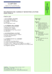
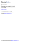
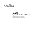
The base architecture for Am186 and Am188 microcontrollers has 14 registers (see Figure
1-1), which are controlled by the instructions detailed in this manual. These registers are
grouped into the following categories.
n General Registers—Eight 16-bit general purpose registers can be used for arithmetic
and logical operands. Four of these (AX, BX, CX, and DX) can be used as 16-bit registers
or split into pairs of separate 8-bit registers (AH, AL, BH, BL, CH, CL, DH, and DL). The
Destination Index (DI) and Source Index (SI) general-purpose registers are used for
data movement and string instructions. The Base Pointer (BP) and Stack Pointer (SP)
general-purpose registers are used for the stack segment and point to the bottom and
top of the stack, respectively.
– Base and Index Registers—Four of the general-purpose registers (BP, BX, DI, and
SI) can also be used to determine offset addresses of operands in memory. These
registers can contain base addresses or indexes to particular locations within a
segment. The addressing mode selects the specific registers for operand and address
calculations.
– Stack Pointer Register—All stack operations (POP, POPA, POPF, PUSH, PUSHA,
PUSHF) utilize the stack pointer. The Stack Pointer (SP) register is always offset
from the Stack Segment (SS) register, and no segment override is allowed.
n Segment Registers—Four 16-bit special-purpose registers (CS, DS, ES, and SS)
select, at any given time, the segments of memory that are immediately addressable
for code (CS), data (DS and ES), and stack (SS) memory.
n Status and Control Registers—Two 16-bit special-purpose registers record or alter certain
aspects of the processor state—the Instruction Pointer (IP) register contains the offset
address of the next sequential instruction to be executed and the Processor Status Flags
(FLAGS) register contains status and control flag bits (see Figure 1-2).
Note that all members of the Am186 and Am188 family of microcontrollers have additional
peripheral registers, which are external to the processor. These peripheral registers are
not directly accessible by the instruction set. However, because the processor treats these
peripheral registers like memory, instructions that have operands that access memory can
also access peripheral registers. The above processor registers, as well as the additional
peripheral registers, are described in the user’s manual for each specific part.
Programming
1-1
Figure 1-1
16-Bit
Register
Name
Byte
Addressable
(8-Bit
Register
Names
Shown)
Register Set
7
0
7
0
AX
AH
AL
DX
DH
CX
16-Bit
Register
Name 15
CS
DL
Multiply/Divide
I/O Instructions
CH
CL
Loop/Shift/Repeat/Count
SS
BX
BH
BL
BP
base pointer
SI
source index
DI
destination index
General
Registers
Code Segment
Data Segment
Stack Segment
ES
Extra Segment
Segment Registers
Index Registers
15
Stack Pointer
15
0
DS
Base Registers
SP
1.1.1
Special
Register
Functions
0
FLAGS
Processor Status Flags
IP
0
Instruction Pointer
Status and Control
Registers
Processor Status Flags Register
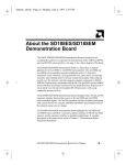
The 16-bit processor status flags register (see Figure 1-2) records specific characteristics
of the result of logical and arithmetic instructions (bits 0, 2, 4, 6, 7, and 11) and controls the
operation of the microcontroller within a given operating mode (bits 8, 9, and 10).
After an instruction is executed, the value of a flag may be set (to 1), cleared/reset (to 0),
unchanged, or undefined. The term undefined means that the flag value prior to the execution
of the instruction is not preserved, and the value of the flag after the instruction is executed cannot
be predicted. The documentation for each instruction indicates how each flag bit is affected by
that instruction.
Figure 1-2
Processor Status Flags Register (FLAGS)
7
15
0
Reserved
OF
AF
DF
PF
Res Res
CF
Res
IF
TF
SF
ZF
Bits 15–12—Reserved.
Bit 11: Overflow Flag (OF)—Set if the signed result cannot be expressed within the number
of bits in the destination operand, cleared otherwise.
1-2
Programming
Bit 10: Direction Flag (DF)—Causes string instructions to auto decrement the appropriate
index registers when set. Clearing DF causes auto-increment. See the CLD and STD
instructions, respectively, for how to clear and set the Direction Flag.
Bit 9: Interrupt-Enable Flag (IF)—When set, enables maskable interrupts to cause the
CPU to transfer control to a location specified by an interrupt vector. See the CLI and STI
instructions, respectively, for how to clear and set the Interrupt-Enable Flag.
Bit 8: Trace Flag (TF)—When set, a trace interrupt occurs after instructions execute. TF
is cleared by the trace interrupt after the processor status flags are pushed onto the stack.
The trace service routine can continue tracing by popping the flags back with an IRET
instruction.
Bit 7: Sign Flag (SF)—Set equal to high-order bit of result (set to 0 if 0 or positive, 1 if
negative).
Bit 6: Zero Flag (ZF)—Set if result is 0; cleared otherwise.
Bit 5: Reserved
Bit 4: Auxiliary Carry (AF)—Set on carry from or borrow to the low-order 4 bits of the AL
general-purpose register; cleared otherwise.
Bit 3: Reserved
Bit 2: Parity Flag (PF)—Set if low-order 8 bits of result contain an even number of 1 bits;
cleared otherwise.
Bit 1: Reserved
Bit 0: Carry Flag (CF)—Set on high-order bit carry or borrow; cleared otherwise. See the
CLC, CMC, and STC instructions, respectively, for how to clear, toggle, and set the Carry
Flag. You can use CF to indicate the outcome of a procedure, such as when searching a
string for a character. For instance, if the character is found, you can use STC to set CF to
1; if the character is not found, you can use CLC to clear CF to 0. Then, subsequent
instructions that do not affect CF can use its value to determine the appropriate course of
action.
1.2
INSTRUCTION SET
Each member of the Am186 and Am188 family of microcontrollers shares the standard 186
instruction set. An instruction can reference from zero to several operands. An operand
can reside in a register, in the instruction itself, or in memory. Specific operand addressing
modes are discussed on page 1-7.
Chapter 2 provides an overview of the instruction set, describing the format of the
instructions. Chapter 3 lists all the instructions for the Am186 and Am188 microcontrollers
in both functional and alphabetical order. Chapter 4 details each instruction.
1.3
MEMORY ORGANIZATION AND ADDRESS GENERATION
The Am186 and Am188 microcontrollers organize memory in sets of segments. Memory
is addressed using a two-component address that consists of a 16-bit segment value and
a 16-bit offset. Each segment is a linear contiguous sequence of 64K (216) 8-bit bytes of
memory in the processor’s address space. The offset is the number of bytes from the
beginning of the segment (the segment address) to the data or instruction which is being
accessed.
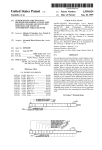
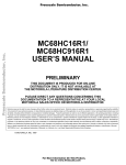
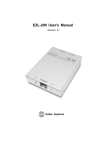
The processor forms the physical address of the target location by taking the segment
address, shifting it to the left 4 bits (multiplying by 16), and adding this to the 16-bit offset.
Programming
1-3
The result is a 20-bit address of the target data or instruction. This allows for a 1-Mbyte physical
address size.
For example, if the segment register is loaded with 12A4h and the offset is 0022h, the
resultant address is 12A62h (see Figure 1-3). To find the result:
1. The segment register contains 12A4h.
2. The segment register is shifted 4 places and is now 12A40h.
3. The offset is 0022h.
4. The shifted segment address (12A40h) is added to the offset (00022h) to get 12A62h.
5. This address is placed on the address bus pins of the controller.
All instructions that address operands in memory must specify (implicitly or explicitly) a 16bit segment value and a 16-bit offset value. The 16-bit segment values are contained in one
of four internal segment registers (CS, DS, ES, and SS). See "Addressing Modes” on page
1-7 for more information on calculating the segment and offset values. See "Segments" on
page 1-5 for more information on the CS, DS, ES, and SS registers.
In addition to memory space, all Am186 and Am188 microcontrollers provide 64K of I/O space
(see Figure 1-4). The I/O space is described on page 1-5.
Figure 1-3
Physical-Address Generation
Shift Left
4 Bits
1
2
A
15
0
0
0
2
15
1
2
A
4
19
4
2
0
0
2
15
1
0
2
2
A
6
2
Physical Address
0
To Memory
Memory and i/O Space
1M
I/O
Space
1-4
Offset
0
0
19
Memory
Space
Logical Address
0
0
Figure 1-4
Segment
Base
64K
Programming
1.4
I/O SPACE
The I/O space consists of 64K 8-bit or 32K 16-bit ports. The IN and OUT instructions address
the I/O space with either an 8-bit port address specified in the instruction, or a 16-bit port
address in the DX register. 8-bit port addresses are zero-extended so that A15–A8 are
Low. I/O port addresses 00F8h through 00FFh are reserved. The Am186 and Am188
microcontrollers provide specific instructions for addressing I/O space.
1.5
SEGMENTS
The Am186 and Am188 microcontrollers use four segment registers:
1. Data Segment (DS): The processor assumes that all accesses to the program’s
variables are from the 64K space pointed to by the DS register. The data segment holds
data, operands, etc.
2. Code Segment (CS): This 64K space is the default location for all instructions. All code
must be executed from the code segment.
3. Stack Segment (SS): The processor uses the SS register to perform operations that
involve the stack, such as pushes and pops. The stack segment is used for temporary
space.
4. Extra Segment (ES): Usually this segment is used for large string operations and for
large data structures. Certain string instructions assume the extra segment as the
segment portion of the address. The extra segment is also used (by using segment
override) as a spare data segment.
When a segment register is not specified for a data movement instruction, it’s assumed to
be a data segment. An instruction prefix can be used to override the segment register (see
"Segment Override Prefix" on page 2-2).For speed and compact instruction encoding, the
segment register used for physical-address generation is implied by the addressing mode
used (see Table 1-1).
Table 1-1
Segment Register Selection Rules
Memory Reference Needed
Segment Register Used
Implicit Segment Selection Rule
Local Data
Data (DS)
All data references
Instructions
Code (CS)
Instructions (including immediate data)
Stack
Stack (SS)
All stack pushes and pops
Any memory references that use the BP register
External Data (Global)
Extra (ES)
All string instruction references that use the DI register as an index
1.6
DATA TYPES
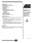
The Am186 and Am188 microcontrollers directly support the following data types:
n Integer—A signed binary numeric value contained in an 8-bit byte or a 16-bit word. All
operations assume a two’s complement representation.
n Ordinal—An unsigned binary numeric value contained in an 8-bit byte or a 16-bit word.
n Double Word—A signed binary numeric value contained in two sequential 16-bit
addresses, or in a DX::AX register pair.
n Quad Word—A signed binary numeric value contained in four sequential 16-bit
addresses.
n BCD—An unpacked byte representation of the decimal digits 0–9.
Programming
1-5
n ASCII—A byte representation of alphanumeric and control characters using the ASCII
standard of character representation.
n Packed BCD—A packed byte representation of two decimal digits (0–9). One digit is
stored in each nibble (4 bits) of the byte.
n String—A contiguous sequence of bytes or words. A string can contain from 1 byte up
to 64 Kbyte.
n Pointer—A 16-bit or 32-bit quantity, composed of a 16-bit offset component or a 16-bit
segment base component plus a 16-bit offset component.
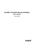
In general, individual data elements must fit within defined segment limits. Figure 1-5
graphically represents the data types supported by the Am186 and Am188 microcontrollers.
Figure 1-5
Signed
Byte
Supported Data Types
7
0
Binary
Coded
Decimal
(BCD)
Sign Bit
Magnitude
Unsigned
Byte
7
0
Signed
Double
Word
Sign Bit
0
87
+3
+1
0
1615
1-6
15
+N
+N
+6
+5
48 47
+4
+3
32 31
+3
+2
+1
16 15
+0
+1
07
0
0
ASCII
ASCII
Character1 Character0
7
0
+1
0 7
0
0
0
Least
Significant Digit
7
+1
0 7
0
0
+2
+1
0
Pointer
0
Segment Base
Magnitude
Unsigned
Word
7
BCD
Digit 0
0
String
...
Byte/WordN
Byte/Word1 Byte/Word0
MSB
+1
0
...
7
0
MSB
+7
0
Most
Significant Digit
+2
31
63
+N
Packed
BCD
MSB
Magnitude
0
07
...
7
0
+1
BCD
Digit 1
BCD
Digit N
Magnitude
Signed
Quad
Word
Sign Bit
7
ASCII
CharacterN
+1
Sign Bit
0
ASCII
MSB
1514
+N
...
7
Magnitude
Signed
Word
7
0
MSB
Magnitude
Programming
Offset
1.7
ADDRESSING MODES
The Am186 and Am188 microcontrollers use eight categories of addressing modes to
specify operands. Two addressing modes are provided for instructions that operate on
register or immediate operands; six modes are provided to specify the location of an
operand in a memory segment.
Register and Immediate Operands
1. Register Operand Mode—The operand is located in one of the 8- or 16-bit registers.
2. Immediate Operand Mode—The operand is included in the instruction.
Memory Operands
A memory-operand address consists of two 16-bit components: a segment value and an
offset. The segment value is supplied by a 16-bit segment register either implicitly chosen
by the addressing mode (described below) or explicitly chosen by a segment override prefix
(see "Segment Override Prefix" on page 2-2). The offset, also called the effective address,
is calculated by summing any combination of the following three address elements:
n Displacement—an 8-bit or 16-bit immediate value contained in the instruction
n Base—contents of either the BX or BP base registers
n Index—contents of either the SI or DI index registers
Any carry from the 16-bit addition is ignored. Eight-bit displacements are sign-extended to
16-bit values.
Combinations of the above three address elements define the following six memory
addressing modes (see Table 1-2 for examples).
1. Direct Mode—The operand offset is contained in the instruction as an 8- or 16-bit
displacement element.
2. Register Indirect Mode—The operand offset is in one of the BP, BX, DI, or SI registers.
3. Based Mode—The operand offset is the sum of an 8- or 16-bit displacement and the contents
of a base register (BP or BX).
4. Indexed Mode—The operand offset is the sum of an 8- or 16-bit displacement and the
contents of an index register (DI or SI).
5. Based Indexed Mode—The operand offset is the sum of the contents of a base register
(BP or BX) and an index register (DI or SI).
6. Based Indexed Mode with Displacement—The operand offset is the sum of a base
register’s contents, an index register’s contents, and an 8-bit or 16-bit displacement.
Table 1-2
Memory Addressing Mode Examples
Addressing Mode
Example
Direct
Register Indirect
Based
Indexed
Based Indexed
Based Indexed with Displacement
mov
mov
mov
mov
mov
mov
Programming
ax,
ax,
ax,
ax,
ax,
ax,
ds:4
[si]
[bx]4
[si]4
[si][bx]
[si][bx]4
1-7
1-8
Programming
CHAPTER
2
2.1
INSTRUCTION SET OVERVIEW
OVERVIEW
The instruction set used by the Am186 and Am188 family of microcontrollers is identical to
the original 8086 and 8088 instruction set, with the addition of seven instructions (BOUND,
ENTER, INS, LEAVE, OUTS, POPA, and PUSHA), and the enhancement of nine
instructions (immediate operands were added to IMUL, PUSH, RCL, RCR, ROL, ROR,
SAL/SHL, SAR, and SHR). In addition, three valid instructions are not supported with the
necessary processor pinout (ESC, LOCK and WAIT). All of these instructions are marked
as such in their description.
2.2
INSTRUCTION FORMAT
When assembling code, an assembler replaces each instruction statement with its
machine-language equivalent. In machine language, all instructions conform to one basic
format. However, the length of an instruction in machine language varies depending on the
operands used in the instruction and the operation that the instruction performs.
An instruction can reference from zero to several operands. An operand can reside in a
register, in the instruction itself, or in memory.
The Am186 and Am188 microcontrollers use the following instruction format. The shortest
instructions consist of only a single opcode byte.
Instruction Prefixes
Segment Override Prefix
Opcode
Operand Address
Displacement
Immediate
2.2.1
Instruction Prefixes
The REP, REPE, REPZ, REPNE and REPNZ prefixes can be used to repeatedly execute
a single string instruction.
The LOCK prefix may be combined with the instruction and segment override prefixes, and
causes the processor to assert its bus LOCK signal while the instruction that follows
executes.
Instruction Set Overview
2-1
2.2.2
Segment Override Prefix
To override the default segment register, place the following byte in front of the instruction,
where RR determines which register is used. Only one segment override prefix can be
used per instruction.
Segment Override
Prefix
0
0
1
R
R 1
1
0
7
6
5
4
3
1
0
2
00 = ES Register
01 = CS Register
10 = SS Register
11 = DS Register
2.2.3
Opcode
This specifies the machine-language opcode for an instruction. The format for the opcodes
is described on page 2-5. Although most instructions use only one opcode byte, the AAD
(D5 0A hex) and AAM (D4 0A hex) instructions use two opcodes.
2.2.4
Operand Address
The following illustration shows the structure of the operand address byte. The operand
address byte controls the addressing for an instruction.
Along with r/m, the Modifier field determines whether the Register/Memory field is
interpreted as a register or the address of a memory operand. For a memory
operand, the Modifier field also indicates whether the operand is addressed directly
or indirectly. For indirectly addressed memory operands, the Modifier field specifies
the number of bytes of displacement that appear in the instruction. See Table 2-1
for mod values.
Along with mod, the Register/Memory field
specifies a general register or the address of a
memory operand. See Table 2-3 for r/m values.
Operand Address
mod
7
6
aux
5
4
r/m
3
2
1
0
The Auxiliary field specifies an opcode extension or a register
that is used as a second operand. See Table 2-2 for aux values
Table 2-1
2-2
mod field
mod
Description
11
r/m is treated as a reg field
00
DISP = 0, disp-low and disp-high are absent
01
DISP = disp-low sign-extended to 16-bits, disp-high
is absent
10
DISP = disp-high: disp-low
Instruction Set Overview
Table 2-2
aux field
aux
If mod=11 and w=0
If mod=11 and w=1
000
AL
AX
001
CL
CX
010
DL
DX
011
BL
BX
100
AH
SP
101
CH
BP
110
DH
SI
111
BH
DI
* – When mod≠11, depends on instruction
Table 2-3
r/m field
r/m
Description
000
EA* = (BX)+(SI)+DISP
001
EA = (BX)+(DI)+DISP
010
EA = (BP)+(SI)+DISP
011
EA = (BP)+(DI)+DISP
100
EA = (SI)+DISP
101
EA = (DI)+DISP
110
EA = (BP)+DISP (except if mod=00, then EA = disp-high:disp:low)
111
EA = (BX)+DISP
* – EA is the Effective Address
2.2.5
Displacement
The displacement is an 8- or 16-bit immediate value to be added to the offset portion of the
address.
2.2.6
Immediate
The immediate bytes contain up to 16 bits of immediate data.
2.3
NOTATION
This parameter
Indicates that
:
The component on the left is the segment for a component located in
memory. The component on the right is the offset.
::
The component on the left is concatenated with the component on the right.
Instruction Set Overview
2-3
2.4
USING THIS MANUAL
Each instruction is detailed in Chapter 4. The following sections explain the format used
when describing each instruction.
2.4.1
Mnemonics and Names
The primary assembly-language mnemonic and its name appear at the top of the first page
for an instruction (see Figure 2-1). Some instructions have additional mnemonics that
perform the same operation. These synonyms are listed below the primary mnemonic.
Figure 2-1
Instruction Mnemonic and Name Sample
MUL
Multiply Unsigned Numbers
2.4.2
Forms of the Instruction
Many instructions have more than one form. The forms for each instruction are listed in a
table just below the mnemonics (see Figure 2-2).
Figure 2-2
Instruction Forms Table Sample
Clocks
Am186
Am188
Form
Opcode
Description
MUL r/m8
F6 /4
AX=(r/m byte)•AL
26–28/32–34
26–28/32–34
MUL r/m16
F7 /4
DX::AX=(r/m word)•AX
35–37/41–43
35–37/45–47
Form
The Form column specifies the syntax for the different forms of an instruction. Each form
includes an instruction mnemonic and zero or more operands. Items in italics are
placeholders for operands that must be provided. A placeholder indicates the size and type
of operand that is allowed.
This operand
imm8
imm16
m
m8
m16
m16&16
m16:16
moffs8
moffs16
ptr16:16
r8
r16
r/m8
r/m16
rel8
rel16
sreg
2-4
Is a placeholder for
An immediate byte: a signed number between –128 and 127
An immediate word: a signed number between –32768 and 32767
An operand in memory
A byte string in memory pointed to by DS:SI or ES:DI
A word string in memory pointed to by DS:SI or ES:DI
A pair of words in memory
A doubleword in memory that contains a full address (segment:offset)
A byte in memory that contains a signed, relative offset displacement
A word in memory that contains a signed, relative offset displacement
A full address (segment:offset)
A general byte register: AL, BL, CL, DL, AH, BH, CH, or DH
A general word register: AX, BX, CX, DX, BP, SP, DI, or SI
A general byte register or a byte in memory
A general word register or a word in memory
A signed, relative offset displacement between –128 and 127
A signed, relative offset displacement between –32768 and 32767
A segment register
Instruction Set Overview
Opcode
The Opcode column specifies the machine-language opcodes for the different forms of an
instruction. (For instruction prefixes, this column also includes the prefix.) Each opcode
includes one or more numbers in hexadecimal format, and zero or more parameters, which
are shown in italics. A parameter provides information about the contents of the Operand
Address byte for that particular form of the instruction.
This parameter
Indicates that
/0–/7
The Auxiliary (aux) Field in the Operand Address byte specifies an
extension (from 0 to 7) to the opcode instead of a register. So for example,
the opcode for adding (ADD) an immediate byte to a general byte register
or a byte in memory is "80 /0 ib". So the second byte of the opcode is
"mod 000 r/m", where mod and r/m are as defined in "Operand Address"
on page 2-2.
/0
The aux field is 0.
/1
The aux field is 1.
/2
The aux field is 2.
/3
The aux field is 3.
/4
The aux field is 4.
/5
The aux field is 5.
/6
The aux field is 6.
/7
The aux field is 7.
/r
The Auxiliary (aux) field in the Operand Address byte specifies a register
instead of an opcode extension. If the Opcode byte specifies a byte register,
the registers are assigned as follows: AL=0, CL=1, DL=2, BL=3, AH=4,
CH=5, DH=6, and BH=7. If the Opcode byte specifies a word register, the
registers are assigned as follows: AX=0, CX=1, DX=2, BX=3, SP=4, BP=5,
SI=6, and DI=7.
/sr
The Auxiliary (aux) field in the Operand Address byte specifies a segment
register as follows: ES=0, CS=1, SS=2, and DS=3.
cb
The byte following the Opcode byte specifies an offset.
cd
The doubleword following the Opcode byte specifies an offset and, in some
cases, a segment.
cw
The word following the Opcode byte specifies an offset and, in some cases,
a segment.
ib
The parameter is an immediate byte. The Opcode byte determines whether
it is interpreted as a signed or unsigned number.
iw
The parameter is an immediate word. The Opcode byte determines whether
it is interpreted as a signed or unsigned number.
rb
The byte register operand is specified in the Opcode byte. To determine
the Opcode byte for a particular register, add the hexadecimal value on the
left of the plus sign to the value of rb for that register, as follows:
AL=0, CL=1, DL=2, BL= 3, AH=4, CH=5, DH=6, and BH=7. So for example,
the opcode for moving an immediate byte to a register (MOV) is "B0+rb".
So B0–B7 are valid opcodes, and B0 is "MOV AL,imm8".
rw
The word register operand is specified in the Opcode byte. To determine
the Opcode byte for a particular register, add the hexadecimal value on the
left of the plus sign to the value of rw for that register, as follows:
AX=0, CX=1, DX=2, BX=3, SP=4, BP=5, SI=6, DI=7.
Instruction Set Overview
2-5
Description
The Description column contains a brief synopsis of each form of the instruction.
Clocks
The Clocks columns (one for the Am186 and one for the Am188 microcontrollers) specify
the number of clock cycles required for the different forms of an instruction.
2.4.3
This parameter
Indicates that
/
The number of clocks required for a register operand is different than the
number required for an operand located in memory. The number to the
left corresponds with a register operand; the number to the right
corresponds with an operand located in memory.
,
The number of clocks depends on the result of the condition tested. The
number to the left corresponds with a True or Pass result, and the number
to the right corresponds with a False or Fail result.
n
The number of clocks depends on the number of times the instruction is
repeated. n is the number of repetitions.
What It Does
This section contains a brief description of the operation the instruction performs.
2.4.4
Syntax
This section shows the syntax for the instruction. Instructions with more than one mnemonic
show the syntax for each mnemonic.
2.4.5
Description
This section contains a more in-depth description of the instruction.
2-6
Instruction Set Overview
2.4.6
Operation It Performs
This section uses a combination of C-language and assembler syntax to describe the
operation of the instruction in detail. In some cases, pseudo-code functions are used to
simplify the code. These functions and the actions they perform are as follows:
Pseudo-Code Function
cat(componenta,componentb)
execute(instruction)
interrupt(type)
interruptRequest()
leastSignificantBit(component)
mostSignificantBit(component)
nextMostSignificantBit(component)
nmiRequest()
operands()
pop()
pow(n,component)
push(component)
resetRequest()
serviceInterrupts()
size(component)
stopExecuting()
2.4.7
Action
Component A is concatenated with component B.
Execute the instruction.
Issue an interrupt request to the microcontroller.
Return True if the microcontroller receives a maskable
interrupt request.
Return the least significant bit of the component.
Return the most significant bit of the component.
Return the next most significant bit of the component.
Return True if the microcontroller receives a nonmaskable
interrupt request.
Return the number of operands present in the instruction.
Read a word from the top of the stack, increment SP, and
return the value.
Raise component to the nth power.
Decrement SP and copy the component to the top of the
stack.
Return True if a device resets the microcontroller by asserting
the RES signal.
Service any pending interrupts.
Return the size of the component in bits.
Suspend execution of current instruction sequence.
Flag Settings After Instruction
This section identifies the flags that are set, cleared, modified according to the result,
unchanged, or left undefined by the instruction. Each instruction has the graphic below,
and shows values for the flag bits after the instruction is performed. A "?" in the bit field
indicates the value is undefined; a "–" indicates the bit value is unchanged. See "Processor
Status Flags Register" on page 1-2 for more information on the flags.
Processor Status
Flags Register
OF DF
IF TF SF ZF
11
9
res
reserved
15
14
13
12
10
8
7
? = undefined; – = unchanged
2.4.8
AF
6
5
PF
res
4
3
CF
res
2
1
0
? = unknown; – = unchanged
Examples
This section contains one or more examples that illustrate possible uses for the instruction.
The beginning of each example is marked with a printout icon; a summary of the example’s
function appears next to it. The example code follows the summary. Note that some of the
examples use assembler directives: CONST (define constant data), DB (define byte), DD
(define double), DW (define word), EQU (equate), LENGTH (length of array), PROC (begin
procedure), SEGMENT (define segment), SIZE (return integer size) and TYPE (return
integer type).
Instruction Set Overview
2-7
2.4.9
Tips
This section contains hints and ideas about some of the ways in which the instruction can
be used.
Tips are marked with this icon.
2.4.10
Related Instructions
This section lists other instructions related to the described instruction.
2-8
Instruction Set Overview
CHAPTER
3
INSTRUCTION SET LISTING
This chapter lists all the instructions for the Am186 and Am188 family of microcontrollers.
The instructions are first grouped by type (see page 3-1) and then listed in alphabetical
order (see page 3-11)
3.1
INSTRUCTION SET BY TYPE
The instructions can be classified into groups according to the type of operation they
perform. Instructions that are used for more than one purpose are listed under each category
to which they belong. The functional groups are:
n "Address Calculation and Translation" on page 3-1
n "Binary Arithmetic" on page 3-2
n "Block-Structured Language" on page 3-3
n "Comparison" on page 3-3
n "Control Transfer" on page 3-3
n "Data Movement" on page 3-5
n "Decimal Arithmetic" on page 3-6
n "Flag" on page 3-7
n "Input/Output" on page 3-8
n "Logical Operation" on page 3-8
n "Processor Control" on page 3-9
n "String" on page 3-9
3.1.1
Address Calculation and Translation
Address Calculation Instructions
Mnemonic
Name
See Page
LDS
Load DS with Segment and Register with Offset
4-131
LEA
Load Effective Address
4-133
LES
Load ES with Segment and Register with Offset
4-138
Address Translation Instructions
Mnemonic
Name
See Page
XLAT
Translate Table Index to Component
4-248
XLATB
Translate Table Index to Byte (Synonym for XLAT)
4-248
Instruction Set Listing
3-1
3.1.2
Binary Arithmetic
The microcontroller supports binary arithmetic using numbers represented in the two’s
complement system. The two’s complement system uses the high bit of an integer (a signed
number) to determine the sign of the number. Unsigned numbers have no sign bit.
Binary Addition Instructions
Mnemonic
Name
See Page
ADC
Add Numbers with Carry
4-10
ADD
Add Numbers
4-14
INC
Increment Number by One
4-69
Binary Subtraction Instructions
Mnemonic
Name
See Page
DEC
Decrement Number by One
4-48
SBB
Subtract Numbers with Borrow
4-216
SUB
Subtract Numbers
4-240
Binary Multiplication Instructions
Mnemonic
Name
See Page
IMUL
Multiply Integers
4-63
MUL
Multiply Unsigned Numbers
4-160
SAL
Shift Arithmetic Left
4-211
SHL
Shift Left (Synonym for SAL)
4-211
Binary Division Instructions
Mnemonic
Name
See Page
DIV
Divide Unsigned Numbers
4-50
IDIV
Divide Integers
4-60
SAR
Shift Arithmetic Right
4-214
SHR
Shift Right
4-225
Binary Conversion Instructions
3-2
Mnemonic
Name
See Page
CBW
Convert Byte Integer to Word
4-24
CWD
Convert Word Integer to Doubleword
4-40
NEG
Two’s Complement Negation
4-163
Instruction Set Listing
3.1.3
Block-Structured Language
Block-Structured Language Instructions
3.1.4
Mnemonic
Name
See Page
ENTER
Enter High-Level Procedure
4-53
LEAVE
Leave High-Level Procedure
4-135
Comparison
General Comparison Instructions
Mnemonic
Name
See Page
CMP
Compare Components
4-34
TEST
Logical Compare
4-243
String Comparison Instructions
3.1.5
Mnemonic
Name
See Page
CMPS
Compare String Components
4-36
CMPSB
Compare String Bytes (Synonym for CMPS)
4-36
CMPSW
Compare String Words (Synonym for CMPS)
4-36
SCAS
Scan String for Component
4-219
SCASB
Scan String for Byte (Synonym for SCAS)
4-219
SCASW
Scan String for Word (Synonym for SCAS)
4-219
Control Transfer
Conditional Jump Instructions to Use after Integer Comparisons
Mnemonic
Name
See Page
JG
Jump If Greater
4-91
JGE
Jump If Greater or Equal
4-93
JL
Jump If Less
4-95
JLE
Jump If Less or Equal
4-97
JNG
Jump If Not Greater (Synonym for JLE)
4-97
JNGE
Jump If Not Greater or Equal (Synonym for JL)
4-95
JNL
Jump If Not Less (Synonym for JGE)
4-93
JNLE
Jump If Not Less or Equal (Synonym for JG)
4-91
Instruction Set Listing
3-3
Conditional Jump Instructions to Use after Unsigned Number Comparisons
Mnemonic
Name
See Page
JA
Jump If Above
4-78
JAE
Jump If Above or Equal
4-80
JB
Jump If Below
4-82
JBE
Jump If Below or Equal
4-84
JNA
Jump If Not Above (Synonym for JBE)
4-84
JNAE
Jump If Not Above or Equal (Synonym for JB)
4-82
JNB
Jump If Not Below (Synonym for JAE)
4-80
JNBE
Jump If Not Below or Equal (Synonym for JA)
4-78
Conditional Jump Instructions That Test for Equality
Mnemonic
Name
See Page
JE
Jump If Equal
4-89
JNE
Jump If Not Equal
4-107
Conditional Jump Instructions That Test Flags
Mnemonic
Name
See Page
JC
Jump If Carry (Synonym for JB)
4-82
JNC
Jump If Not Carry (Synonym for JAE)
4-80
JNO
Jump If Not Overflow
4-113
JNP
Jump If Not Parity (Synonym for JPO)
4-124
JNS
Jump If Not Sign
4-116
JNZ
Jump If Not Zero (Synonym for JNE)
4-107
JO
Jump If Overflow
4-119
JP
Jump If Parity (Synonym for JPE)
4-121
JPE
Jump If Parity Even
4-122
JPO
Jump If Parity Odd
4-124
JS
Jump If Sign
4-126
JZ
Jump If Zero (Synonym for JE)
4-89
Conditional Interrupt Instructions
3-4
Mnemonic
Name
See Page
BOUND
Check Array Index Against Bounds
4-19
IDIV
Divide Integers
4-60
INTO
Generate Interrupt If Overflow (Conditional form of INT)
4-73
Instruction Set Listing
Conditional Loop Instructions
Mnemonic
Name
See Page
JCXZ
Jump If CX Register Is Zero
4-87
LOOP
Loop While CX Register is Not Zero
4-146
LOOPE
Loop If Equal
4-148
LOOPNE
Loop If Not Equal
4-150
LOOPNZ
Loop If Not Zero (Synonym for LOOPNE)
4-150
LOOPZ
Loop If Zero (Synonym for LOOPE)
4-148
Unconditional Transfer Instructions
3.1.6
Mnemonic
Name
See Page
CALL
Call Procedure
4-21
INT
Generate Interrupt
4-73
IRET
Interrupt Return
4-76
JMP
Jump Unconditionally
4-99
RET
Return from Procedure
4-202
Data Movement
General Movement Instructions
Mnemonic
Name
See Page
MOV
Move Component
4-153
XCHG
Exchange Components
4-246
String Movement Instructions
Mnemonic
Name
See Page
LODS
Load String Component
4-141
LODSB
Load String Byte (Synonym for LODS)
4-141
LODSW
Load String Word (Synonym for LODS)
4-141
MOVS
Move String Component
4-156
MOVSB
Move String Byte (Synonym for MOVS)
4-156
MOVSW
Move String Word (Synonym for MOVS)
4-156
STOS
Store String Component
4-237
STOSB
Store String Byte (Synonym for STOS)
4-237
STOSW
Store String Word (Synonym for STOS)
4-237
Instruction Set Listing
3-5
Stack Movement Instructions
Mnemonic
Name
See Page
POP
Pop Component from Stack
4-175
POPA
Pop All 16-Bit General Registers from Stack
4-178
POPF
Pop Flags from Stack
4-180
PUSH
Push Component onto Stack
4-181
PUSHA
Push All 16-Bit General Registers onto Stack
4-184
PUSHF
Push Flags onto Stack
4-186
General I/O Movement Instructions
Mnemonic
Name
See Page
IN
Input Component from Port
4-67
OUT
Output Component to Port
4-171
String I/O Movement Instructions
Mnemonic
Name
See Page
INS
Input String Component from Port
4-71
INSB
Input String Byte from Port (Synonym for INS)
4-71
INSW
Input String Word from Port (Synonym for INS)
4-71
OUTS
Output String Component to Port
4-173
OUTSB
Output String Byte to Port (Synonym for OUTS)
4-173
OUTSW
Output String Word to Port (Synonym for OUTS)
4-173
Flag Movement Instructions
3.1.7
Mnemonic
Name
See Page
LAHF
Load AH with Flags
4-129
SAHF
Store AH in Flags
4-209
Decimal Arithmetic
In addition to binary arithmetic, the microcontroller supports arithmetic using numbers
represented in the binary-coded decimal (BCD) system. The BCD system uses four bits to
represent a single decimal digit. When two decimal digits are stored in a byte, the number
is called a packed decimal number. When only one decimal digit is stored in a byte, the
number is called an unpacked decimal number.
To perform decimal arithmetic, the microcontroller uses a subset of the binary arithmetic
instructions and a special set of instructions that convert unsigned binary numbers to
decimal.
Arithmetic Instructions That Are Used with Decimal Numbers
3-6
Mnemonic
Name
See Page
ADD
Add Numbers
4-14
DIV
Divide Unsigned Numbers
4-50
MUL
Multiply Unsigned Numbers
4-160
SUB
Subtract Numbers
4-240
Instruction Set Listing
Unpacked-Decimal Adjustment Instructions
Mnemonic
Name
See Page
AAA
ASCII Adjust AL After Addition
4-2
AAD
ASCII Adjust AX Before Division
4-4
AAM
ASCII Adjust AL After Multiplication
4-6
AAS
ASCII Adjust AL After Subtraction
4-8
Packed-Decimal Adjustment Instructions
Mnemonic
Name
See Page
DAA
Decimal Adjust AL After Addition
4-42
DAS
Decimal Adjust AL After Subtraction
4-45
Consider using decimal arithmetic instead of binary arithmetic under the following
circumstances:
n When the numbers you are using represent only decimal quantities.
Manipulating numbers in binary and converting them back and forth between binary and
decimal can introduce rounding errors.
n When you need to read or write many ASCII numbers.
Converting a number between ASCII and decimal is simpler than converting it between
ASCII and binary.
3.1.8
Flag
Single-Flag Instructions
Mnemonic
Name
See Page
CLC
Clear Carry Flag
4-26
CLD
Clear Direction Flag
4-29
CLI
Clear Interrupt-Enable Flag
4-31
CMC
Complement Carry Flag
4-33
RCL
Rotate through Carry Left
4-187
RCR
Rotate through Carry Right
4-189
STC
Set Carry Flag
4-228
STD
Set Direction Flag
4-231
STI
Set Interrupt-Enable Flag
4-235
Multiple-Flag Instructions
Mnemonic
Name
See Page
POPF
Pop Flags from Stack
4-180
SAHF
Store AH in Flags
4-209
Instruction Set Listing
3-7
3.1.9
Input/Output
General I/O Instructions
Mnemonic
Name
See Page
IN
Input Component from Port
4-67
OUT
Output Component to Port
4-171
String I/O Instructions
3.1.10
Mnemonic
Name
See Page
INS
Input String Component from Port
4-71
INSB
Input String Byte from Port (Synonym for INS)
4-71
INSW
Input String Word from Port (Synonym for INS)
4-71
OUTS
Output String Component to Port
4-173
OUTSB
Output String Byte to Port (Synonym for OUTS)
4-173
OUTSW
Output String Word to Port (Synonym for OUTS)
4-173
Logical Operation
Boolean Operation Instructions
Mnemonic
Name
See Page
AND
Logical AND
4-17
NOT
One’s Complement Negation
4-167
OR
Logical Inclusive OR
4-169
XOR
Logical Exclusive OR
4-251
Shift Instructions
Mnemonic
Name
See Page
SAL
Shift Arithmetic Left
4-211
SAR
Shift Arithmetic Right
4-214
SHL
Shift Left (Synonym for SAL)
4-211
SHR
Shift Right
4-225
Rotate Instructions
3-8
Mnemonic
Name
See Page
RCL
Rotate through Carry Left
4-187
RCR
Rotate through Carry Right
4-189
ROL
Rotate Left
4-205
ROR
Rotate Right
4-207
Instruction Set Listing
3.1.11
Processor Control
Processor Control Instructions
Mnemonic
Name
See Page
HLT
Halt
4-57
LOCK
Lock the Bus
4-140
NOP
No Operation
4-165
Coprocessor Interface Instructions
3.1.12
Mnemonic
Name
See Page
ESC
Escape
4-56
WAIT
Wait for Coprocessor 4-245
String
A string is a contiguous sequence of components stored in memory. For example, a string
might be composed of a list of ASCII characters or a table of numbers.
A string instruction operates on a single component in a string. To manipulate more than
one component in a string, the string instruction prefixes (REP/REPE/REPNE/REPNZ/
REPZ) can be used to repeatedly execute the same string instruction.
A string instruction uses an index register as the offset of a component in a string. Most
string instructions operate on only one string, in which case they use either the Source
Index (SI) register or the Destination Index (DI) register. String instructions that operate on
two strings use SI as the offset of a component in one string and DI as the offset of the
corresponding component in the other string.
After executing a string instruction, the microcontroller automatically increments or
decrements SI and DI so that they contain the offsets of the next components in their strings.
The microcontroller determines the amount by which the index registers must be
incremented or decremented based on the size of the components.
The microcontroller can process the components of a string in a forward direction (from
lower addresses to higher addresses), or in a backward direction (from higher addresses
to lower ones). The microcontroller uses the value of the Direction Flag (DF) to determine
whether to increment or decrement SI and DI. If DF is cleared to 0, the microcontroller
increments the index registers; otherwise, it decrements them.
String-Instruction Prefixes
Mnemonic
Name
See Page
REP
Repeat
4-191
REPE
Repeat While Equal
4-193
REPNE
Repeat While Not Equal
4-197
REPNZ
Repeat While Not Zero (Synonym for REPNE)
4-197
REPZ
Repeat While Zero (Synonym for REPE)
4-193
Instruction Set Listing
3-9
String Direction Instructions
Mnemonic
Name
See Page
CLD
Clear Direction Flag
4-29
STD
Set Direction Flag
4-231
String Movement Instructions
Mnemonic
Name
See Page
LODS
Load String Component
4-141
LODSB
Load String Byte (Synonym for LODS)
4-141
LODSW
Load String Word (Synonym for LODS)
4-141
MOVS
Move String Component
4-156
MOVSB
Move String Byte (Synonym for MOVS)
4-156
MOVSW
Move String Word (Synonym for MOVS)
4-156
STOS
Store String Component
4-237
STOSB
Store String Byte (Synonym for STOS)
4-237
STOSW
Store String Word (Synonym for STOS)
4-237
String Comparison Instructions
Mnemonic
Name
See Page
CMPS
Compare String Components
4-36
CMPSB
Compare String Bytes (Synonym for CMPS)
4-36
CMPSW
Compare String Words (Synonym for CMPS)
4-36
SCAS
Scan String for Component
4-219
SCASB
Scan String for Byte (Synonym for SCAS)
4-219
SCASW
Scan String for Word (Synonym for SCAS)
4-219
String I/O Instructions
3-10
Mnemonic
Name
See Page
INS
Input String Component from Port
4-71
INSB
Input String Byte from Port (Synonym for INS)
4-71
INSW
Input String Word from Port (Synonym for INS)
4-71
OUTS
Output String Component to Port
4-173
OUTSB
Output String Byte to Port (Synonym for OUTS)
4-173
OUTSW
Output String Word to Port (Synonym for OUTS)
4-173
Instruction Set Listing
3.2
INSTRUCTION SET IN ALPHABETICAL ORDER
Table 3-1 provides an alphabetical list of the instruction set for the Am186 and Am188
microcontrollers.
Table 3-1
Instruction Set
Mnemonic
AAA
AAD
AAM
AAS
ADC
ADD
AND
BOUND
CALL
CBW
CLC
CLD
CLI
CMC
CMP
CMPS
CMPSB
CMPSW
CWD
DAA
DAS
DEC
DIV
ENTER
ESC
HLT
IDIV
IMUL
IN
INC
INS
INSB
INSW
INT
INTO
IRET
JA
JAE
JB
JBE
JC
JCXZ
Instruction Name
ASCII Adjust AL After Addition
ASCII Adjust AX Before Division
ASCII Adjust AL After Multiplication
ASCII Adjust AL After Subtraction
Add Numbers with Carry
Add Numbers
Logical AND
Check Array Index Against Bounds
Call Procedure
Convert Byte Integer to Word
Clear Carry Flag
Clear Direction Flag
Clear Interrupt-Enable Flag
Complement Carry Flag
Compare Components
Compare String Components
Compare String Bytes (Synonym for CMPS)
Compare String Words (Synonym for CMPS)
Convert Word Integer to Doubleword
Decimal Adjust AL After Addition
Decimal Adjust AL After Subtraction
Decrement Number by One
Divide Unsigned Numbers
Enter High-Level Procedure
Escape
Halt
Divide Integers
Multiply Integers
Input Component from Port
Increment Number by One
Input String Component from Port
Input String Byte from Port (Synonym for INS)
Input String Word from Port (Synonym for INS)
Generate Interrupt
Generate Interrupt If Overflow (Conditional form of INT)
Interrupt Return
Jump If Above
Jump If Above or Equal
Jump If Below
Jump If Below or Equal
Jump If Carry (Synonym for JB)
Jump If CX Register Is Zero
Instruction Set Listing
See Page
4-2
4-4
4-6
4-8
4-10
4-14
4-17
4-19
4-21
4-24
4-26
4-29
4-31
4-33
4-34
4-36
4-36
4-36
4-40
4-42
4-45
4-48
4-50
4-53
4-56
4-57
4-60
4-63
4-67
4-69
4-71
4-71
4-71
4-73
4-73
4-76
4-78
4-80
4-82
4-84
4-82
4-87
3-11
Table 3-1
Instruction Set (continued)
Mnemonic
JE
JG
JGE
JL
JLE
JMP
JNA
JNAE
JNB
JNBE
JNC
JNE
JNG
JNGE
JNL
JNLE
JNO
JNP
JNS
JNZ
JO
JP
JPE
JPO
JS
JZ
LAHF
LDS
LEA
LEAVE
LES
LOCK
LODS
LODSB
LODSW
LOOP
LOOPE
LOOPNE
LOOPNZ
LOOPZ
MOV
MOVS
MOVSB
MOVSW
MUL
NEG
NOP
3-12
Instruction Name
Jump If Equal
Jump If Greater
Jump If Greater or Equal
Jump If Less
Jump If Less or Equal
Jump Unconditionally
Jump If Not Above (Synonym for JBE)
Jump If Not Above or Equal (Synonym for JB)
Jump If Not Below (Synonym for JAE)
Jump If Not Below or Equal (Synonym for JA)
Jump If Not Carry (Synonym for JAE)
Jump If Not Equal
Jump If Not Greater (Synonym for JLE)
Jump If Not Greater or Equal (Synonym for JL)
Jump If Not Less (Synonym for JGE)
Jump If Not Less or Equal (Synonym for JG)
Jump If Not Overflow
Jump If Not Parity (Synonym for JPO)
Jump If Not Sign
Jump If Not Zero (Synonym for JNE)
Jump If Overflow
Jump If Parity (Synonym for JPE)
Jump If Parity Even
Jump If Parity Odd
Jump If Sign
Jump If Zero (Synonym for JE)
Load AH with Flags
Load DS with Segment and Register with Offset
Load Effective Address
Leave High-Level Procedure
Load ES with Segment and Register with Offset
Lock the Bus
Load String Component
Load String Byte (Synonym for LODS)
Load String Word (Synonym for LODS)
Loop While CX Register Is Not Zero
Loop If Equal
Loop If Not Equal
Loop If Not Zero (Synonym for LOOPNE)
Loop If Zero (Synonym for LOOPE)
Move Component
Move String Component
Move String Byte (Synonym for MOVS)
Move String Word (Synonym for MOVS)
Multiply Unsigned Numbers
Two’s Complement Negation
No Operation
Instruction Set Listing
See Page
4-89
4-91
4-93
4-95
4-97
4-99
4-84
4-82
4-80
4-78
4-80
4-107
4-97
4-95
4-93
4-91
4-113
4-124
4-116
4-107
4-119
4-122
4-122
4-124
4-126
4-89
4-129
4-131
4-133
4-135
4-138
4-140
4-141
4-141
4-141
4-146
4-148
4-150
4-150
4-148
4-153
4-156
4-156
4-156
4-160
4-163
4-165
Table 3-1
Instruction Set (continued)
Mnemonic
NOT
OR
OUT
OUTS
OUTSB
OUTSW
POP
POPA
POPF
PUSH
PUSHA
PUSHF
RCL
RCR
REP
REPE
REPNE
REPNZ
REPZ
RET
ROL
ROR
SAHF
SAL
SAR
SBB
SCAS
SCASB
SCASW
SHL
SHR
STC
STD
STI
STOS
STOSB
STOSW
SUB
TEST
WAIT
XCHG
XLAT
XLATB
XOR
Instruction Name
One’s Complement Negation
Logical Inclusive OR
Output Component to Port
Output String Component to Port
Output String Byte to Port (Synonym for OUTS)
Output String Word to Port (Synonym for OUTS)
Pop Component from Stack
Pop All 16-Bit General Registers from Stack
Pop Flags from Stack
Push Component onto Stack
Push All 16-Bit General Registers onto Stack
Push Flags onto Stack
Rotate through Carry Left
Rotate through Carry Right
Repeat
Repeat While Equal
Repeat While Not Equal
Repeat While Not Zero (Synonym for REPNE)
Repeat While Zero (Synonym for REPE)
Return from Procedure
Rotate Left
Rotate Right
Store AH in Flags
Shift Arithmetic Left
Shift Arithmetic Right
Subtract Numbers with Borrow
Scan String for Component
Scan String for Byte (Synonym for SCAS)
Scan String for Word (Synonym for SCAS)
Shift Left (Synonym for SAL)
Shift Right
Set Carry Flag
Set Direction Flag
Set Interrupt-Enable Flag
Store String Component
Store String Byte (Synonym for STOS)
Store String Word (Synonym for STOS)
Subtract Numbers
Logical Compare
Wait for Coprocessor
Exchange Components
Translate Table Index to Component
Translate Table Index to Byte (Synonym for XLAT)
Logical Exclusive OR
Instruction Set Listing
See Page
4-167
4-169
4-171
4-173
4-173
4-173
4-175
4-178
4-180
4-181
4-184
4-186
4-187
4-189
4-191
4-193
4-197
4-197
4-193
4-202
4-205
4-207
4-209
4-211
4-214
4-216
4-219
4-219
4-219
4-211
4-225
4-228
4-231
4-235
4-237
4-237
4-237
4-240
4-243
4-245
4-246
4-248
4-248
4-251
3-13
3-14
Instruction Set Listing
CHAPTER
4
4.1
INSTRUCTION SET
INSTRUCTIONS
This chapter contains a complete description of each instruction that is supported by the
Am186 and Am188 family of microcontrollers. For an explanation of the format of each
instruction, see Chapter 2.
Instruction Set
4-1
AAA
ASCII Adjust AL After Addition
AAA
Clocks
Am186
Am188
Form
Opcode
Description
AAA
37
ASCII-adjust AL after addition
8
8
What It Does
AAA converts an 8-bit unsigned binary number that is the sum of two unpacked decimal
(BCD) numbers to its unpacked decimal equivalent.
Syntax
AAA
Description
Use the AAA instruction after an ADD or ADC instruction that leaves a byte result in the
AL register. The lower nibbles of the operands of the ADD or ADC instruction should be in
the range 0–9 (BCD digits). The AAA instruction adjusts the AL register to contain the
correct decimal digit result. If the addition produced a decimal carry, AAA increments the
AH register and sets the Carry and Auxiliary-Carry Flags (CF and AF). If there is no decimal
carry, AAA clears CF and AF and leaves the AH register unchanged. AAA sets the top
nibble of the AL register to 0.
Operation It Performs
if (((AL = AL & 0x0F) > 9) || (AF == 1))
/* AL is not yet in BCD format */
/* (note high nibble of AL is cleared either way) */
{
/* convert AL to decimal and unpack */
AL = (AL + 6) & 0x0F;
AH = AH + 1;
/* set carry flags */
CF = AF = 1;
}
else
/* clear carry flags */
CF = AF = 0;
Flag Settings After Instruction
OF DF
Processor Status
Flags Register
reserved
15
14
13
12
IF TF SF ZF
AF
?
–
–
–
?
? res
11
10
9
8
7
6
5
PF
CF
res ? res
4
3
2
1
0
? = undefined; – = unchanged
AF=1 if carry or borrow to low nibble CF=1 for carry or borrow to high-order bit
AF=0 otherwise
CF=0 otherwise
4-2
Instruction Set
AAA
AAA
Examples
This example adds two unpacked decimal numbers.
UADDEND1
UADDEND2
DB
DB
05h
07h
; add unpacked decimal numbers
XOR
AX,AX
MOV
AL,UADDEND1
ADD
AL,UADDEND2
AAA
; the AF and CF flags will be set,
; 5 unpacked BCD
; 7 unpacked BCD
; clear AX
; AL = 05h = 5
; AX = 000Ch =
; AX = 0102h =
indicating the
unpacked BCD
12
12 unpacked BCD
carry into AH
Tips
To convert an unpacked decimal digit to its ASCII equivalent, use OR after AAA to add 30h
(ASCII 0) to the digit.
ADC, ADD, SBB, and SUB set AF when the result needs to be converted for decimal
arithmetic. AAA, AAS, DAA, and DAS use AF to determine whether an adjustment is
needed. This is the only use for AF.
Related Instructions
If you want to
See
Add two numbers and the value of CF
Add two numbers
ADC
ADD
Convert an 8-bit unsigned binary sum to its packed decimal equivalent
DAA
Instruction Set
4-3
AAD
ASCII Adjust AX Before Division
AAD
Clocks
Am186
Am188
Form
Opcode
Description
AAD
D5 0A
ASCII-adjust AX before division
15
15
What It Does
AAD converts a two-digit unpacked decimal (BCD) number—ordinarily the dividend of an
unpacked decimal division—to its unsigned binary equivalent.
Syntax
AAD
Description
AAD prepares two unpacked BCD digits—the least significant digit in the AL register and
the most significant digit in the AH register—for division by an unpacked BCD digit. The
instruction sets the AL register to AL + (10•AH) and then clears the AH register. The AX
register then equals the binary equivalent of the original unpacked two-digit number.
Operation It Performs
/* convert AX to binary */
AL = (AH * 10) + AL;
AH = 0;
Flag Settings After Instruction
OF DF
Processor Status
Flags Register
?
–
–
–
11
10
9
8
reserved
15
14
13
12
IF TF SF ZF
AF
PF
res ? res
7
6
5
4
3
CF
res ?
2
1
0
? = undefined; – = unchanged
SF=1 if result is 0 or positive
SF=0 if result is negative
ZF=1 if result equal to 0
ZF=0 if result not equal to 0
PF=1 if low byte of result has even number of set bits
PF=0 otherwise
Examples
This example divides a two-digit unpacked decimal number by a one-digit unpacked
decimal number.
UDIVIDEND
UDIVISOR
DW
DB
0409h
03h
; 49 unpacked BCD
; 3 unpacked BCD
; divide unpacked decimal numbers (two digit by one digit)
MOV
AX,UDIVIDEND
; AX = 0409h = 49 unpacked BCD
AAD
; AX = 0031h = 49
DIV
UDIVISOR
; AL = 10h = 16, the quotient
; AH = 01h = 1, the remainder
MOV
BL,AH
; save remainder, BL = 01h = 1
AAM
; AX = 0106h = 16 unpacked BCD
4-4
Instruction Set
AAD
AAD
This example uses AAD to convert a two-digit unpacked decimal number to its binary
equivalent.
UBCD
DW
0801h
; 81 unpacked BCD
; convert unpacked decimal number to binary
MOV
AX,UBCD
; AX = 0801h = 81 unpacked BCD
AAD
; AX = 0051h = 81
Tips
The microcontroller can only divide unpacked decimal numbers. To divide packed decimal
numbers, unpack them first.
Related Instructions
If you want to
See
Divide an unsigned number by another unsigned number
DIV
Instruction Set
4-5
AAM
ASCII Adjust AL After Multiplication
AAM
Clocks
Am186
Am188
Form
Opcode
Description
AAM
D4 0A
ASCII-adjust AL after multiplication
19
19
What It Does
AAM converts an 8-bit unsigned binary number—ordinarily the product of two unpacked
decimal (BCD) numbers—to its unpacked decimal equivalent.
Syntax
AAM
Description
Use AAM only after executing the MUL instruction between two unpacked BCD operands
with the result in the AX register. Because the result is 99 or less, it resides entirely in the
AL register. AAM unpacks the AL result by dividing AL by 10, leaving the quotient (most
significant digit) in AH and the remainder (least significant digit) in AL.
Operation It Performs
/* convert AL to decimal */
AH = AL / 10;
AL = AL % 10;
Flag Settings After Instruction
OF DF
Processor Status
Flags Register
reserved
15
14
13
12
IF TF SF ZF
?
–
–
–
11
10
9
8
AF
PF
res ? res
7
6
5
4
3
CF
res ?
2
1
0
? = undefined; – = unchanged
SF=1 if result is 0 or positive
SF=0 if result is negative
ZF=1 if result equal to 0
ZF=0 if result not equal to 0
PF=1 if low byte of result has even number of set bits
PF=0 otherwise
Examples
This example multiplies two unpacked decimal digits.
UMULTIPLICAND
UMULTIPLIER
DB
DB
07h
06h
; 7 unpacked BCD
; 6 unpacked BCD
; multiply unpacked decimal numbers
MOV
AL,UMULTIPLICAND
; AL = 07h = 7 unpacked BCD
MUL
UMULTIPLIER
; AL = 2Ah = 42
AAM
; AX = 0402h = 42 unpacked BCD
4-6
Instruction Set
AAM
AAM
This example uses AAM to divide an unsigned binary number by 10. (The binary number
must be 99 or less.) Note that the quotient occupies the high byte of the result, and the
remainder occupies the low byte of the result. If you use DIV to divide an unsigned number
by 10, the quotient and remainder occupy the opposite halves of the result.
UBINARY
DB
44h
; 68
; divide unsigned binary number by 10
MOV
AL,UBINARY
; AL = 44h = 68
AAM
; AH = 06h = 6, the quotient
; AL = 08h = 8, the remainder
Tips
The microcontroller can only multiply unpacked decimal numbers. To multiply packed
decimal numbers, unpack them first.
To convert an unpacked decimal digit to its ASCII equivalent, use OR after AAM to add
30h (ASCII 0) to the digit.
Related Instructions
If you want to
See
Multiply two unsigned numbers
MUL
Instruction Set
4-7
AAS
ASCII Adjust AL After Subtraction
AAS
Clocks
Am186
Am188
Form
Opcode
Description
AAS
3F
ASCII-adjust AL after subtraction
7
7
What It Does
AAS converts an 8-bit unsigned binary number that is the difference of two unpacked
decimal (BCD) numbers to its unpacked decimal equivalent.
Syntax
AAS
Description
Use AAS only after a SUB or SBB instruction that leaves the byte result in AL. The lower
nibbles of the operands of the SUB or SBB instruction must be in the range 0–9 (BCD).
AAS adjusts AL so that it contains the correct decimal result. If the subtraction produced a
decimal borrow, AAS decrements AH and sets CF and AF. If there is no decimal borrow,
AAS clears CF and AF and leaves AH unchanged. AAS sets the top nibble of AL to 0.
Operation It Performs
if (((AL = AL & 0x0F) > 9) || (AF == 1))
/* AL is not yet decimal */
/* (note high nibble of AL is cleared either way */
{
/* convert AL to decimal and unpack */
AL = (AL - 6) & 0x0F;
AH = AH - 1;
/* set carry flags */
CF = AF = 1;
}
else
/* clear carry flags */
CF = AF = 0;
Flag Settings After Instruction
Processor Status
Flags Register
reserved
15
14
13
12
OF DF
IF TF SF ZF
AF
?
–
–
–
?
? res
11
10
9
8
7
6
5
PF
CF
res ? res
4
3
2
1
0
? = undefined; – = unchanged
AF=1 if carry or borrow to low nibble CF=1 for carry or borrow to high-order bit
AF=0 otherwise
CF=0 otherwise
4-8
Instruction Set
AAS
AAS
Examples
This example subtracts one unpacked decimal number (the subtrahend) from another
unpacked decimal number (the minuend).
UMINUEND
USUBTRAHEND
DW
DB
0103h
05h
; 13 unpacked BCD
; 5 unpacked BCD
; subtract unpacked decimal numbers
MOV
AX,UMINUEND
; AX = 0103h = 13 unpacked BCD
SUB
AL,USUBTRAHEND
; AX = 01FEh
AAS
; AL = 08h = 8 unpacked BCD
Tips
To convert an unpacked decimal digit to its ASCII equivalent, use OR after AAS to add 30h
(ASCII 0) to the digit.
ADC, ADD, SBB, and SUB set AF when the result needs to be converted for decimal
arithmetic. AAA, AAS, DAA, and DAS use AF to determine whether an adjustment is
needed. This is the only use for AF.
Related Instructions
If you want to
See
Convert an 8-bit unsigned binary difference to its packed decimal equivalent
Subtract a number and the value of CF from another number
DAS
SBB
Subtract a number from another number
SUB
Instruction Set
4-9
ADC
Add Numbers with Carry
ADC
Clocks
Am186
Am188
Form
Opcode
Description
ADC AL,imm8
14 ib
Add immediate byte to AL with carry
3
3
ADC AX,imm16
15 iw
Add immediate word to AX with carry
4
4
ADC r/m8,imm8
80 /2 ib
Add immediate byte to r/m byte with carry
4/16
4/16
ADC r/m16,imm16
81 /2 iw
Add immediate word to r/m word with carry
4/16
4/20
ADC r/m16,imm8
83 /2 ib
Add sign-extended immediate byte to r/m word with carry
4/16
4/20
ADC r/m8,r8
10 /r
Add byte register to r/m byte with carry
3/10
3/10
ADC r/m16,r16
11 /r
Add word register to r/m word with carry
3/10
3/14
ADC r8,r/m8
12 /r
Add r/m byte to byte register with carry
3/10
3/10
ADC r16,r/m16
13 /r
Add r/m word to word register with carry
3/10
3/14
What It Does
ADC adds two integers or unsigned numbers and the value of the Carry Flag (CF).
Syntax
ADC sum,addend
Description
ADC performs an integer addition of the two operands and the value of CF. ADC assigns
the result to sum and sets CF as required. ADC is typically part of a multibyte or multiword
addition operation. ADC sign-extends immediate-byte values to the appropriate size before
adding to a word operand.
Operation It Performs
if (addend == imm8)
if (size(sum) > 8)
/* extend sign of addend */
if (addend < 0)
addend = 0xFF00 | addend;
else
addend = 0x00FF & addend;
/* add with carry */
sum = sum + addend + CF;
4-10
Instruction Set
ADC
ADC
Flag Settings After Instruction
OF DF
Processor Status
Flags Register
–
–
–
10
9
8
reserved
15
14
13
12
11
IF TF SF ZF
AF
res
7
6
5
PF
res
4
3
CF
res
2
1
0
? = undefined; – = unchanged
OF=1 if result larger than destination operand
OF=0 otherwise
PF=1 if low byte of result has even number of set bits
PF=0 otherwise
SF=1 if result is 0 or positive
SF=0 if result is negative
ZF=1 if result equal to 0
ZF=0 if result not equal to 0
CF=1 for carry or borrow to high-order bit
CF=0 otherwise
AF=1 if carry or borrow to low nibble
AF=0 otherwise
Examples
This example adds two 32-bit unsigned numbers.
UADDEND1
UADDEND2
DD
DD
592535620
3352720
; 23516044h
; 00332890h
; 32-bit unsigned addition: UADDEND1 = UADDEND1 + UADDEND2
; add left words (bytes and words reversed in memory)
MOV
AX,WORD PTR UADDEND2
ADD
WORD PTR UADDEND1,AX
; add right words
MOV
AX,WORD PTR UADDEND2+2
ADC
WORD PTR UADDEND1+2,AX
Instruction Set
; UADDEND1 = 238488D4h
; = 595888340
4-11
ADC
ADC
This example adds two 3-byte packed decimal numbers.
PADDEND1
PADDEND2
DB
DB
00h,25h,86h,17h
00h,04h,21h,45h
; 258617 packed BCD
; 42145 packed BCD
; multibyte packed decimal addition: PADDEND1 = PADDEND1 + PADDEND2
; add right bytes
MOV
AL,PADDEND1 + 3
ADD
AL,PADDEND2 + 3
DAA
MOV
PADDEND1 + 3,AL
; add next bytes
MOV
AL,PADDEND1 + 2
ADC
AL,PADDEND2 + 2
DAA
MOV
PADDEND1 + 2,AL
; add next bytes
MOV
AL,PADDEND1 + 1
ADC
AL,PADDEND2 + 1
DAA
MOV
PADDEND1 + 1,AL
; if CF is 1, propagate carry into left byte
JC
ADD_CARRY
JMP
CONTINUE
ADD_CARRY:
MOV
PADDEND1,1
CONTINUE:
...
Tips
To add two integers or two unsigned numbers that are both stored in memory, copy one
of them to a register before using ADC.
ADC requires both operands to be the same size. Before adding an 8-bit integer to a 16bit integer, convert the 8-bit integer to its 16-bit equivalent using CBW. To convert an 8-bit
unsigned number to its 16-bit equivalent, use MOV to copy 0 to AH.
To add numbers larger than 16 bits, use ADD to add the low words, and then use ADC to
add each of the subsequently higher words.
The microcontroller does not provide an instruction that performs decimal addition. To add
decimal numbers, use ADD to perform binary addition, and then convert the result to decimal
using AAA or DAA.
ADC, ADD, SBB, and SUB set AF when the result needs to be converted for decimal
arithmetic. AAA, AAS, DAA, and DAS use AF to determine whether an adjustment is
needed. This is the only use for AF.
4-12
Instruction Set
ADC
ADC
Related Instructions
If you want to
See
Convert an 8-bit unsigned binary sum to its unpacked decimal equivalent
Add two numbers
AAA
ADD
Convert an 8-bit integer to its 16-bit equivalent
Convert an 8-bit unsigned binary sum to its packed decimal equivalent
CBW
DAA
Change the sign of an integer
NEG
Instruction Set
4-13
ADD
Add Numbers
ADD
Clocks
Am186
Am188
Form
Opcode
Description
ADD AL,imm8
04 ib
Add immediate byte to AL
3
3
ADD AX,imm16
05 iw
Add immediate word to AX
4
4
ADD r/m8,imm8
80 /0 ib
Add immediate byte to r/m byte
4/16
4/16
ADD r/m16,imm16
81 /0 iw
Add immediate word to r/m word
4/16
4/20
ADD r/m16,imm8
83 /0 ib
Add sign-extended immediate byte to r/m word
4/16
4/20
ADD r/m8,r8
00 /r
Add byte register to r/m byte
3/10
3/10
ADD r/m16,r16
01 /r
Add word register to r/m word
3/10
3/14
ADD r8,r/m8
02 /r
Add r/m byte to byte register
3/10
3/10
ADD r16,r/m16
03 /r
Add r/m word to word register
3/10
3/14
What It Does
ADD adds two integers or unsigned numbers.
Syntax
ADD sum,addend
Description
ADD performs an integer addition of the two operands. ADD assigns the result to sum and
sets the flags accordingly. ADD sign-extends immediate byte values to the appropriate size
before adding to a word operand.
Operation It Performs
if (addend == imm8)
if (size(sum) > 8)
/* extend sign of addend */
if (addend < 0)
addend = 0xFF00 | addend;
else
addend = 0x00FF & addend;
/* add */
sum = sum + addend;
4-14
Instruction Set
ADD
ADD
Flag Settings After Instruction
OF DF
Processor Status
Flags Register
–
–
–
10
9
8
reserved
15
14
13
12
11
IF TF SF ZF
AF
res
7
6
5
PF
res
4
3
CF
res
2
1
0
? = undefined; – = unchanged
OF=1 if result larger than destination operand
OF=0 otherwise
CF=1 for carry or borrow to high-order bit
CF=0 otherwise
PF=1 if low byte of result has even number of set bits
PF=0 otherwise
SF=1 if result is 0 or positive
SF=0 if result is negative
AF=1 if carry or borrow to low nibble
AF=0 otherwise
ZF=1 if result equal to 0
ZF=0 if result not equal to 0
Examples
This example adds two 16-bit integers.
SADDEND1
SADDEND2
DW
DW
-6360
723
; add signed numbers
MOV
AX,SADDEND2
ADD
SADDEND1,AX
; E6ECh
; 02D3h
; AX = 723
; SADDEND1 = -5637
This example adds two 32-bit unsigned numbers.
UADDEND1
UADDEND2
DD
DD
592535620
3352720
; 23516044h
; 00332890h
; 32-bit unsigned addition: UADDEND1 = UADDEND1 + UADDEND2
; add left words (bytes and words reversed in memory)
MOV
AX,WORD PTR UADDEND2
; AX=2890h
ADD
WORD PTR UADDEND1,AX
; UADEND1=2351h::(2890h+6044h)
=235188D4h
; add right words
MOV
AX,WORD PTR UADDEND2+2 ; AX=0033h
ADC
WORD PTR UADDEND1+2,AX ; UADDEND1=(2351h+0033h)::88D4h
;
=238488D4h
;
=595888340
Tips
To add two integers or two unsigned numbers that are both stored in memory, copy one
of them to a register before using ADD.
ADD requires both operands to be the same size. Before adding an 8-bit integer to a 16bit integer, convert the 8-bit integer to its 16-bit equivalent using CBW. To convert an 8-bit
unsigned number to its 16-bit equivalent, use MOV to copy 0 to AH.
To add numbers larger than 16 bits, use ADD to add the low words, and then use ADC to
add each of the subsequently higher words.
Use INC instead of ADD within a loop when you want to increase a value by 1 each time
the loop is executed.
Instruction Set
4-15
ADD
ADD
The microcontroller does not provide an instruction that performs decimal addition. To add
decimal numbers, use ADD to perform binary addition, and then convert the result to decimal
using AAA or DAA.
ADC, ADD, SBB, and SUB set AF when the result needs to be converted for decimal
arithmetic. AAA, AAS, DAA, and DAS use AF to determine whether an adjustment is
needed. This is the only use for AF.
Related Instructions
4-16
If you want to
See
Convert an 8-bit unsigned binary sum to its unpacked decimal equivalent
AAA
Add two numbers and the value of CF
Convert an 8-bit integer to its 16-bit equivalent
ADC
CBW
Convert an 8-bit unsigned binary sum to its packed decimal equivalent
Add 1 to a number
DAA
INC
Change the sign of an integer
NEG
Instruction Set
AND
Logical AND
AND
Clocks
Am186
Am188
Form
Opcode
Description
AND AL,imm8
24 ib
AND immediate byte with AL
3
3
AND AX,imm16
25 iw
AND immediate word with AX
4
4
AND r/m8,imm8
80 /4 ib
AND immediate byte with r/m byte
4/16
4/16
AND r/m16,imm16
81 /4 iw
AND immediate word with r/m word
4/16
4/20
AND r/m16,imm8
83 /4 ib
AND sign-extended immediate byte with r/m word
4/16
4/20
AND r/m8,r8
20 /r
AND byte register with r/m byte
3/10
3/10
AND r/m16,r16
21 /r
AND word register with r/m word
3/10
3/14
AND r8,r/m8
22 /r
AND r/m byte with byte register
3/10
3/10
AND r16,r/m16
23 /r
AND r/m word with word register
3/10
3/14
What It Does
AND clears particular bits of a component to 0 according to a mask.
Syntax
AND component,mask
Description
AND computes the logical AND of the two operands. If corresponding bits of the operands
are 1, the resulting bit is 1. If either bit or both are 0, the result is 0. The answer replaces
component.
Operation It Performs
/* AND component with mask */
component = component & mask;
/* clear overflow and carry flags */
OF = CF = 0;
Flag Settings After Instruction
OF DF
Processor Status
Flags Register
reserved
15
14
13
12
IF TF SF ZF
0
–
–
–
11
10
9
8
AF
PF
res ? res
7
6
5
4
3
CF
res 0
2
1
0
? = undefined; – = unchanged
SF=1 if result is 0 or positive
SF=0 if result is negative
ZF=1 if result equal to 0
ZF=0 if result not equal to 0
PF=1 if low byte of result has even number of set bits
PF=0 otherwise
Instruction Set
4-17
AND
AND
Examples
This example converts an ASCII number to its unpacked decimal equivalent.
BCD_MASK
ASCII_NUM
EQU
DB
0Fh
36h
; convert ASCII number to decimal
MOV
AL,ASCII_NUM
AND
AL,BCD_MASK
; ASCII-to-decimal mask
; ASCII ’6’
; AL = 36h = ASCII ”6”
; AL = 06h = decimal 6
This example extracts the middle byte of a word so it can be used by another instruction.
SETTINGS
DW
1234h
; extract middle byte of AX and place in AH
MOV
AX,SETTINGS ; AX = 1234h
AND
AX,0FF0h
; mask middle byte: AX = 0230h
SHL
AX,4
; shift middle byte into AH: AX = 2300h
Tips
To convert an ASCII number (30–39h) to its unpacked decimal equivalent, use AND with
a mask of 0Fh to clear the bits in the high nibble of the byte.
Related Instructions
4-18
If you want to
See
Toggle all bits of a component
NOT
Set particular bits of a component to 1
Toggle particular bits of a component
OR
XOR
Instruction Set
BOUND*Check Array Index Against Bounds
BOUND
Form
Opcode
Description
Clocks
Am186
Am188
BOUND r16,m16&16
62 /r
Check to see if word register is within bounds
33–35
33–35
What It Does
BOUND determines whether an integer falls between two boundaries.
Syntax
BOUND index,bounds
Description
BOUND ensures that a signed array index is within the limits specified by a block of memory
between an upper and lower bound. The first operand (from the specified register) must
be greater than or equal to the lower bound value, but not greater than the upper bound.
The lower bound value is stored at the address specified by the second operand. The upper
bound value is stored at a consecutive higher memory address (+2). If the first operand is
out of the specified bounds, BOUND issues an Interrupt 5 Request. The saved IP points
to the BOUND instruction.
Operation It Performs
if ((index < [bounds]) || (index > [bounds + 2]))
/* integer is outside of boundaries */
interrupt(5);
Flag Settings After Instruction
OF DF
Processor Status
Flags Register
reserved
15
14
13
12
IF TF SF ZF
AF
PF
CF
–
–
–
–
–
– res – res – res –
11
10
9
8
7
6
5
4
3
2
1
0
? = undefined; – = unchanged
* – This instruction was not available on the original 8086/8088 systems.
Instruction Set
4-19
BOUND
BOUND
Examples
This example compares a word in a table to the value in AX. Before the comparison, BOUND
checks to see if the table index is within the range of the table. If it is not, the microcontroller
generates Interrupt 5.
BOUNDARIES
TABLE
DW
DW
0,256
4096 DUP (?)
; search table for value in AX
; fill table with values and load AX with search key
CALL
FILL_TABLE
CALL
GET_KEY
; load SI with index
...
; check index before comparison
BOUND
SI,BOUNDARIES
; if out of bounds, call interrupt 5
CMP
TABLE[SI],AX
; compare components
...
Tips
Use BOUND to check a signed index value to see if it falls within the range of an array.
Related Instructions
4-20
If you want to
See
Compare two components using subtraction and set the flags accordingly
CMP
Generate an interrupt
INT
Instruction Set
CALL
Call Procedure
CALL
Clocks
Am186
Am188
Form
Opcode
Description
CALL rel16
E8 cw
Call near, displacement relative to next instruction
CALL r/m16
FF /2
Call near, register indirect/memory indirect
CALL ptr16:16
9A cd
CALL m16:16
FF /3
15
19
13/19
17/27
Call far to full address given
23
31
Call far to address at m16:16 word
38
54
What It Does
CALL calls a procedure.
Syntax
CALL procedure
Description
CALL suspends execution of the current instruction sequence, saves the segment (if
necessary) and offset addresses of the next instruction, and begins executing the procedure
named by the operand. A return at the end of the called procedure exits the procedure and
starts execution at the instruction following the CALL instruction.
CALL rel16 and CALL r/m16 are near calls. They use the current Code Segment register
value. Near calls push the offset of the next instruction (IP) onto the stack. The near RET
instruction in the procedure pops the instruction offset when it returns control.
n Near direct calls (relative): CALL rel16 adds a signed offset to the address of the next
instruction to determine the destination. CALL stores the result in the IP register.
n Near indirect calls (absolute): CALL r/m16 specifies a register or memory location
from which the 16-bit absolute segment offset is fetched. CALL stores the result in the
IP register.
CALL ptr16:16 and CALL m16:16 are far calls. They use a long pointer to the called
procedure. The long pointer provides 16 bits for the CS register and 16 for the IP register.
Far calls push both the CS and IP registers as a return address. A far return must be used
to pop both CS and IP from the stack.
n Far direct calls: CALL ptr16:16 uses a 4-byte operand as a long pointer to the called
procedure.
n Far indirect calls: CALL m16:16 fetches the long pointer from the memory location
specified (indirection).
A CALL-indirect-through-memory, using the stack pointer (SP) as a base register,
references memory before the call. The base is the value of SP before the instruction
executes.
Instruction Set
4-21
CALL
CALL
Operation It Performs
/* save return offset */
push(IP);
if (procedure == rel16)
/* near direct call */
IP = IP + rel16;
if (procedure == r/m16)
/* near indirect call */
IP = [r/m16];
if ((procedure == ptr16:16) || (procedure == m16:16))
/* far call */
{
/* save return segment */
push(CS);
if (procedure == ptr16:16)
/* far direct call */
CS:IP = ptr16:16;
else
/* far indirect call */
CS:IP = [m16:16];
}
Flag Settings After Instruction
OF DF
Processor Status
Flags Register
reserved
15
14
13
12
IF TF SF ZF
AF
PF
CF
–
–
–
–
–
– res – res – res –
11
10
9
8
7
6
5
4
3
2
1
0
? = undefined; – = unchanged
Examples
This example calls a procedure whose address is stored in a doubleword in memory.
PROC_ADDR
DD
?
; full address of current procedure
; store address of current procedure in PROC_ADDR
...
LDS
SI,PROC_ADDR
; load segment of procedure into DS
; and offset of procedure into SI
; call procedure at address stored in doubleword in memory
CALL
DWORD PTR [SI]
4-22
Instruction Set
CALL
CALL
Tips
The assembler generates the correct call (near or far) based on the declaration of the called
procedure.
Related Instructions
If you want to
See
Stop executing the current sequence of instructions and begin executing another JMP
End a procedure and return to the calling procedure
RET
Instruction Set
4-23
CBW
Convert Byte Integer to Word
CBW
Clocks
Am186
Am188
Form
Opcode
Description
CBW
98
Put signed extension of AL in AX
2
2
What It Does
CBW converts an 8-bit integer to a sign-extended 16-bit integer.
Syntax
CBW
Description
CBW converts the signed byte in the AL register to a signed word in the AX register by
extending the most significant bit of the AL register (the sign bit) into all of the bits of the
AH register.
Operation It Performs
/* extend sign of AL to AX */
if (AL < 0)
AH = 0xFF;
else
AH = 0x00;
Flag Settings After Instruction
OF DF
Processor Status
Flags Register
15
14
13
12
IF TF SF ZF
AF
PF
CF
–
–
–
–
–
– res – res – res –
11
10
9
8
7
6
reserved
5
4
3
2
1
0
? = undefined; – = unchanged
Examples
This example converts an 8-bit integer to its 16-bit equivalent before adding it to another
16-bit integer.
SADDEND1
SADDEND2
DB
DW
-106
25000
; 96h
; 61A8h
; add word integer to byte integer
MOV
AL,SADDEND1
; AL = 96h = -106
CBW
; AX = FF96h = -106
ADD
AX,SADDEND2
; AX = 613Eh = 24894
4-24
Instruction Set
CBW
CBW
This example converts an 8-bit integer to its 16-bit equivalent before dividing it by an 8-bit
integer.
SDIVIDEND
SDIVISOR
DB
DB
101
-3
; divide byte integers
MOV
AL,SDIVIDEND
CBW
IDIV
SDIVISOR
; 65h
; FDh
;
;
;
,
AL
AX
AL
AH
=
=
=
=
65h =
0065h
DFh =
02h =
101
= 101
-33, the quotient
2, the remainder
Tips
To convert an 8-bit unsigned number in AL to its 16-bit equivalent, use MOV to copy 0 to AH.
Related Instructions
If you want to
See
Add two numbers with the value of CF
Add two numbers
ADC
ADD
Convert a 16-bit integer to its 32-bit equivalent
Divide an integer by another integer
CWD
IDIV
Subtract a number and the value of CF from another number
SBB
Subtract a number from another number
SUB
Instruction Set
4-25
CLC
Clear Carry Flag
CLC
Clocks
Am186
Am188
Form
Opcode
Description
CLC
F8
Clear Carry Flag
2
2
What It Does
CLC clears the Carry Flag (CF) to 0.
Syntax
CLC
Description
CLC clears CF.
Operation It Performs
/* clear carry flag */
CF = 0;
Flag Settings After Instruction
OF DF
Processor Status
Flags Register
reserved
15
14
13
12
IF TF SF ZF
AF
PF
CF
–
–
–
–
–
– res – res – res 0
11
10
9
8
7
6
5
4
3
2
1
0
? = undefined; – = unchanged
Examples
This example rotates the bits of a byte to the left, making sure that the high bit remains 0.
; rotate byte, maintaining 0 in high bit
MOV
AL,01101011b
; AL = 01101011b
CLC
; CF = 0
RCR
AL,1
; AL = 00110101b, CF = 1
4-26
Instruction Set
CLC
CLC
This example scans a string in memory until it finds a character or until the entire string is
scanned. The microcontroller scans the bytes, one by one, from first to last. If the string
contains the character, the microcontroller sets the Carry Flag (CF) to 1; otherwise, it clears
CF to 0.
STRING
NULL
DB
EQU
10 DUP (?)
0
; notify assembler that DS and ES specify
; the same segment of memory
ASSUME DS:DATASEG, ES:DATASEG
; set up segment registers
MOV
AX,DATASEG
MOV
DS,AX
MOV
ES,AX
with same segment
; copy data segment to AX
; copy AX to DS
; copy AX to ES
; initialize and use string
...
; set up registers and flags
MOV
AL,NULL
;
LEA
DI,STRING
;
MOV
CX,LENGTH STRING
;
CLD
;
REPNE
copy character to AL
load offset (segment = ES)
set up counter
process string low to high
; scan string for character
SCASB
; if string contains character
JE
FOUND
; else
JMP
NOT_FOUND
FOUND:
STC
JMP
NOT_FOUND:
CLC
; indicate found
CONTINUE
; indicate not found
CONTINUE:
...
Instruction Set
4-27
CLC
CLC
Tips
You can use CF to indicate the outcome of a procedure, such as when searching a string
for a character. For instance, if the character is found, you can use STC to set CF to 1; if
the character is not found, you can use CLC to clear CF to 0. Then, subsequent instructions
that do not affect CF can use its value to determine the appropriate course of action.
To rotate a 0 into a component, use CLC to clear CF to 0 before using RCL or RCR.
Related Instructions
4-28
If you want to
See
Toggle the value of CF
CMC
Rotate the bits of a component and CF to the left
RCL
Rotate the bits of a component and CF to the right
Set CF to 1
RCR
STC
Instruction Set
CLD
Clear Direction Flag
CLD
Clocks
Am186
Am188
Form
Opcode
Description
CLD
FC
Clear Direction Flag so the Source Index (SI) and/or the
Destination Index (DI) registers will increment during
string instructions
2
2
What It Does
CLD clears the Direction Flag (DF) to 0, causing subsequent repeated string instructions
to process the components of a string from a lower address to a higher address.
Syntax
CLD
Description
CLD clears DF, causing subsequent string operations to increment the index registers on
which they operate: SI and/or DI.
Operation It Performs
/* process string components from lower to higher addresses */
DF = 0;
Flag Settings After Instruction
OF DF
Processor Status
Flags Register
reserved
15
14
13
12
IF TF SF ZF
AF
PF
CF
–
0
–
–
–
– res – res – res –
11
10
9
8
7
6
5
4
3
2
1
0
? = undefined; – = unchanged
Examples
This example fills a string in memory with a character. Because the Direction Flag (DF) is
cleared to 0 using CLD, the bytes are filled, one by one, from first to last.
STRING
POUND
DB
DB
128 DUP (?)
’#’
; 2Ah
; fill string with character
; set up registers and flags
MOV
AX,SEG STRING
MOV
ES,AX
MOV
AL,POUND
LEA
DI,STRING
MOV
CX,LENGTH STRING
CLD
REP
;
;
;
;
copy character to AL
load offset (segment = ES)
set up counter
process string going forward
; fill string
STOSB
Instruction Set
4-29
CLD
CLD
This example copies one string of 16-bit integers in memory to another string in the same
segment. Because the Direction Flag (DF) is cleared to 0 using CLD, the microcontroller
copies the words, one by one, from first to last.
; defined in SEG_1 segment
SOURCE
DW
350,-4821,-276,449,10578
DEST
DW
5 DUP (?)
; direct assembler that DS and ES point to
; the same segment of memory
ASSUME DS:SEG_1, ES:SEG_1
; set up DS and ES with same segment address
MOV
AX,SEG_1
; copy data segment to AX
MOV
DS,AX
; copy AX to DS
MOV
ES,AX
; copy AX to ES
; set up registers and flags
LEA
SI,SOURCE
; load source offset (segment = DS)
LEA
DI,DEST
; load dest. offset (segment = ES)
MOV
CX,5
; set up counter
CLD
; process string low to high
REP
; copy source string to destination string
MOVSW
Tips
Before using one of the string instructions (CMPS, INS, LODS, MOVS, OUTS, SCAS, or
STOS), always set up CX with the length of the string, and use CLD (forward) or STD
(backward) to establish the direction for string processing.
The string instructions always advance SI and/or DI, regardless of the use of the REP prefix.
Be sure to set or clear DF before any string instruction.
Related Instructions
4-30
If you want to
See
Compare a component in one string with a component in another string
Copy a component from a port in I/O memory to a string in main memory
CMPS
INS
Copy a component from a string in memory to a register
LODS
Copy a component from one string in memory to another string in memory
Copy a component from a string in main memory to a port in I/O memory
MOVS
OUTS
Compare a string component located in memory to a register
Process string components from higher to lower addresses
SCAS
STD
Copy a component from a register to a string in memory
STOS
Instruction Set
CLI
Clear Interrupt-Enable Flag
CLI
Clocks
Am186
Am188
Form
Opcode
Description
CLI
FA
Clear Interrupt-Enable Flag (IF)
2
2
What It Does
CLI clears the Interrupt-Enable Flag (IF), disabling all maskable interrupts.
Syntax
CLI
Description
CLI clears IF. Maskable external interrupts are not recognized at the end of the CLI
instruction—or from that point on—until IF is set.
Operation It Performs
/* disable maskable interrupts */
IF = 0;
Flag Settings After Instruction
OF DF
Processor Status
Flags Register
reserved
15
14
13
12
IF TF SF ZF
AF
PF
CF
–
–
0
–
–
– res – res – res –
11
10
9
8
7
6
5
4
3
2
1
0
? = undefined; – = unchanged
Instruction Set
4-31
CLI
CLI
Examples
This example of an interrupt-service routine: enables interrupts so that interrupt nesting
can occur, resets a device, disables interrupts until the interrupted procedure is resumed,
and then clears the in-service bits in the In-Service (INSERV) register by writing to the EndOf-Interrupt (EOI) register.
; the microcontroller pushes the flags onto
; the stack before executing this routine
; enable interrupt nesting during routine
ISR1
PROC
FAR
PUSHA
STI
; save general registers
; enable unmasked maskable interrupts
mRESET_DEVICE1
CLI
; perform operation (macro)
; disable maskable interrupts until IRET
; reset
MOV
MOV
OUT
in-service bits by writing to EOI register
DX,INT_EOI_ADDR
; address of EOI register
AX,8000h
; non-specific EOI
DX,AX
; write to EOI register
POPA
IRET
ISR1
; restore general registers
ENDP
; the microcontroller pops the flags from the stack
; before returning to the interrupted procedure
Tips
When the Interrupt-Enable Flag (IF) is cleared to 0 so that all maskable interrupts are
disabled, you can still use INT to generate an interrupt, even if it is masked by its interrupt
control register.
Software interrupts and traps, and nonmaskable interrupts are not affected by the IF flag.
The IRET instruction restores the value of the Processor Status Flags register from the
value pushed onto the stack when the interrupt was taken. Modifying the Processor Status
Flags register via the STI, CLI or other instruction will not affect the flags after the IRET.
If you disable maskable interrupts using CLI, the microcontroller does not recognize
maskable interrupt requests until the instruction that follows STI is executed.
After using CLI to disable maskable interrupts, use STI to enable them as soon as possible
to reduce the possibility of missing maskable interrupt requests.
Related Instructions
If you want to
See
Enable maskable interrupts that are not masked by their interrupt control registers STI
4-32
Instruction Set
CMC
Complement Carry Flag
CMC
Clocks
Am186
Am188
Form
Opcode
Description
CMC
F5
Complement Carry Flag
2
2
What It Does
CMC toggles the value of the Carry Flag (CF).
Syntax
CMC
Description
CMC reverses the setting of CF.
Operation It Performs
/* toggle value of carry flag */
CF = ~ CF;
Flag Settings After Instruction
OF DF
Processor Status
Flags Register
reserved
15
14
13
12
IF TF SF ZF
AF
PF
CF
–
–
–
–
–
– res – res – res
11
10
9
8
7
6
5
4
3
2
1
0
? = undefined; – = unchanged
CF contains the complement of its original value
Related Instructions
If you want to
See
Clear the value of CF to 0
CLC
Rotate the bits of a component and CF to the left
Rotate the bits of a component and CF to the right
RCL
RCR
Set the value of CF to 1
STC
Instruction Set
4-33
CMP
Compare Components
CMP
Clocks
Am186
Am188
Form
Opcode
Description
CMP AL,imm8
3C ib
Compare immediate byte to AL
3
3
CMP AX,imm16
3D iw
Compare immediate word to AX
4
4
CMP r/m8,imm8
80 /7 ib
Compare immediate byte to r/m byte
3/10
3/10
CMP r/m16,imm16
81 /7 iw
Compare immediate word to r/m word
3/10
3/14
CMP r/m16,imm8
83 /7 ib
Compare sign-extended immediate byte to r/m word
3/10
3/14
CMP r/m8,r8
38 /r
Compare byte register to r/m byte
3/10
3/10
CMP r/m16,r16
39 /r
Compare word register to r/m word
3/10
3/14
CMP r8,r/m8
3A /r
Compare r/m byte to byte register
3/10
3/10
CMP r16,r/m16
3B /r
Compare r/m word to word register
3/10
3/14
What It Does
CMP compares two components using subtraction and sets the flags accordingly.
Syntax
CMP value1,value2
Description
CMP subtracts the second operand from the first, but does not store the result. CMP only
changes the flag settings. The CMP instruction is typically used in conjunction with
conditional jumps. If an operand greater than one byte is compared to an immediate byte,
the byte value is first sign-extended.
Operation It Performs
if (value2 == imm8)
if (size(value1) > 8)
/* extend sign of value2 */
if (value2 < 0)
value2 = 0xFF00 | value2;
else
value2 = 0x00FF & value2;
/* compare values */
temp = value1 - value2;
/* don’t store result, but set appropriate flags */
4-34
Instruction Set
CMP
CMP
Flag Settings After Instruction
OF DF
Processor Status
Flags Register
–
–
–
10
9
8
reserved
15
14
13
12
11
IF TF SF ZF
AF
res
7
6
5
PF
res
4
3
CF
res
2
1
0
? = undefined; – = unchanged
OF=1 if result larger than destination operand
OF=0 otherwise
CF=1 for carry or borrow to high-order bit
CF=0 otherwise
PF=1 if low byte of result has even number of set bits
PF=0 otherwise
SF=1 if result is 0 or positive
SF=0 if result is negative
AF=1 if carry or borrow to low nibble
AF=0 otherwise
ZF=1 if result equal to 0
ZF=0 if result not equal to 0
Examples
This example waits for a character from the serial port. DEC, JCXZ, and JMP implement
a construct equivalent to the C-language do-while loop. CMP and JNE implement an
if statement within the loop.
; loop for a maximum number of times or until a
; serial-port character is ready
MOV
CX,100h
LOOP_TOP:
CHAR_READY
CMP
AH,0
JNE
GOT_CHAR
DEC
CX
JCXZ
NO_CHAR
JMP
LOOP_TOP
; set up counter
;
;
;
;
;
;
read character into AH (macro)
is a character ready?
if so, then jump out with character
subtract 1 from counter
if CX is 0, jump out without character
if not, jump to top of loop
GOT_CHAR:
...
NO_CHAR:
...
Tips
Don’t compare signed values with unsigned values. Compare either two integers or two
unsigned numbers.
Related Instructions
If you want to
See
Determine whether particular bits of a component are set to 1
TEST
Instruction Set
4-35
CMPS Compare String Components
CMPSB Compare String Bytes
CMPSW Compare String Words
CMPS
Clocks
Am186
Am188
Form
Opcode
Description
CMPS m8,m8
A6
Compare byte ES:[DI] to byte segment:[SI]
22
22
CMPS m16,m16
A7
Compare word ES:[DI] to word segment:[SI]
22
26
CMPSB
A6
Compare byte ES:[DI] to byte DS:[SI]
22
22
CMPSW
A7
Compare word ES:[DI] to word DS:[SI]
22
26
What It Does
CMPS compares a component in one string to a component in another string.
Syntax
CMPS source,destination
CMPSB
CMPSW
To override the default source
segment (DS) and to have the
assembler type-check your operands,
use this form. In this form, source is
segment:[SI]. The assembler uses the
segment in DS unless you specify a
different segment register as part of
the source string component. The
assembler uses the definitions of the
string components to determine their
sizes.
To compare a byte within a string
located in the destination segment
specified in ES to a byte within a string
located in the source segment
specified in DS, use this form.
Regardless of the form of CMPS
you use, destination is always
ES:[DI]. Before using any form of
CMPS, make sure that: ES
contains the segment of the
destination string, DI contains
the offset of the destination
string, and SI contains the offset
of the source string.
To compare a word within a string
located in the destination segment
specified in ES to a word within a string
located in the source segment
specified in DS, use this form.
Description
CMPS compares the byte or word pointed to by the SI register with the byte or word pointed
to by the DI register. You must preload the registers before executing CMPS.
CMPS subtracts the DI indexed operand from the SI indexed operand. No result is stored;
only the flags reflect the change. The operand size determines whether bytes or words are
compared. The first operand (SI) uses the DS register unless a segment override byte is
present. The second operand (DI) must be addressable from the ES register; no segment
override is possible. After the comparison, both the source-index register and the
destination-index register are automatically advanced. If DF is 0, the registers increment
according to the operand size (byte=1; word=2); if DF is 1, the registers decrement.
CMPSB and CMPSW are synonymous with the byte and word CMPS instructions,
respectively.
4-36
Instruction Set
CMPS
CMPS
Operation It Performs
if (size(destination) == 8)
/* compare bytes */
{
temp = DS:[SI] - ES:[DI];
if (DF == 0)
increment = 1;
else
increment = -1;
}
/* compare */
/* forward */
/* backward */
if (size(destination) == 16)
/* compare words */
{
temp = DS:[SI] - ES:[DI];
if (DF == 0)
increment = 2;
else
increment = -2;
}
/* forward */
/* backward */
/* point to next string component */
SI = SI + increment;
DI = DI + increment;
Flag Settings After Instruction
OF DF
Processor Status
Flags Register
–
–
–
10
9
8
reserved
15
14
13
12
11
IF TF SF ZF
AF
res
7
6
5
PF
res
4
3
CF
res
2
1
0
? = undefined; – = unchanged
OF=1 if result larger than destination operand
OF=0 otherwise
SF=1 if result is 0 or positive
SF=0 if result is negative
ZF=1 if result equal to 0
ZF=0 if result not equal to 0
CF=1 for carry or borrow to high-order bit
CF=0 otherwise
PF=1 if low byte of result has even number of set bits
PF=0 otherwise
AF=1 if carry or borrow to low nibble
AF=0 otherwise
Instruction Set
4-37
CMPS
CMPS
Examples
This example compares for equality one string of nonzero words stored in the segment
specified in ES to another string of nonzero words located in the same segment. The
microcontroller compares the words, one by one, from first to last, unless any two words
being compared don’t match. If both strings are the same, the microcontroller loads 0 into
AX; otherwise, it loads the word that was different in the second string into AX.
; defined in SEG_E segment
STRING1
DW
64 DUP (?)
STRING2
DW
LENGTH STRING1 DUP (?)
; compare strings for equality
; notify assembler: DS and ES point to
; different segments of memory
ASSUME DS:SEG_D, ES:SEG_E
; set up DS and ES with different segment addresses
MOV
AX,SEG_D
; load one segment into DS
MOV
DS,AX
; DS points to SEG_D
MOV
AX,SEG_E
; load another segment into ES
MOV
ES,AX
; ES points to SEG_E
; initialize and use strings
...
; set up registers and flags
LEA
SI,ES:STRING1
; load source offset (segment = ES)
LEA
DI,STRING2
; load dest. offset (segment = ES)
MOV
CX,LENGTH STRING1 ; set up counter
CLD
; process string low to high
REPE
; compare strings for equality using segment override
; for source
CMPS
ES:STRING1,STRING2
; if both strings are the same, then jump
JE
SAME
; else, load unequal word into AX
MOV
AX,STRING2[DI]
JMP
CONTINUE
SAME:
; indicate both strings are the same
MOV
AX,0
CONTINUE:
...
4-38
Instruction Set
CMPS
CMPS
Tips
Before using CMPS, always set up CX with the length of the string, and use CLD (forward)
or STD (backward) to establish the direction for string processing.
To determine whether one string is the same as another, use the REPE (or REPZ) prefix
to execute CMPS repeatedly. If all the corresponding components match, ZF is set to 1.
To determine whether one string is different from another, use the REPNE (or REPNZ)
prefix to execute CMPS repeatedly. If no corresponding components match, ZF is cleared
to 0.
The string instructions always advance SI and/or DI, regardless of the use of the REP prefix.
Be sure to set or clear DF before any string instruction.
Related Instructions
If you want to
See
Process string components from lower to higher addresses
CLD
Repeat one string comparison instruction while the components are the same
REPE
Repeat one string comparison instruction while the components are not the same REPNE
Compare a component in a string to a register
Process string components from higher to lower addresses
Instruction Set
SCAS
STD
4-39
CWD
Convert Word Integer to Doubleword
CWD
Clocks
Am186
Am188
Form
Opcode
Description
CWD
99
Put signed extension of AX in DX::AX
4
4
What It Does
CWD converts a 16-bit integer to a sign-extended 32-bit integer.
Syntax
CWD
Description
CWD converts the signed word in the AX register to a signed doubleword in the DX::AX
register pair by extending the most significant bit of the AX register into all the bits of the
DX register.
Operation It Performs
/* extend sign of AX into DX */
if (AX < 0)
DX = 0xFFFF;
else
DX = 0x0000;
Flag Settings After Instruction
OF DF
Processor Status
Flags Register
reserved
15
14
13
12
IF TF SF ZF
AF
PF
CF
–
–
–
–
–
– res – res – res –
11
10
9
8
7
6
? = undefined; – = unchanged
5
4
3
2
1
0
? = unknown; – = unchanged
Examples
This example divides one 16-bit integer by another 16-bit integer.
SDIVIDEND
SDIVISOR
DW
DW
5800
-45
; divide word integers
MOV
AX,SDIVIDEND
CWD
IDIV
SDIVISOR
4-40
; 16A8h
; FFD3h
;
;
;
;
AX = 16A8h = 5800
DX::AX = 000016A8h = 5800
AX = FF80h = -128, the quotient
DX = 0028h = -40, the remainder
Instruction Set
CWD
CWD
This example divides one 16-bit integer by another 16-bit integer.
SDIVIDEND
SDIVISOR
DW
DW
-1675
200
; divide word integers
MOV
AX,SDIVIDEND
CWD
IDIV
SDIVISOR
; F975h
; 00C8h
;
;
;
;
AX = F975h = -1675
DX::AX = FFFFF975h = -1675
AX = FFF8h = -8, the quotient
DX = FFB5h = -75, the remainder
Tips
If you want to divide a 16-bit integer (the dividend) by another 16-bit integer (the divisor):
use MOV to copy the dividend to AX, use CWD to convert the dividend into its 32-bit
equivalent, and then use IDIV to perform the division.
Related Instructions
If you want to
See
Convert an 8-bit integer to its 16-bit equivalent
CBW
Divide an integer by another integer
IDIV
Instruction Set
4-41
DAA
Decimal Adjust AL After Addition
DAA
Clocks
Am186
Am188
Form
Opcode
Description
DAA
27
Decimal-adjust AL after addition
4
4
What It Does
DAA converts an 8-bit unsigned binary number that is the sum of two single-byte packed
decimal (BCD) numbers to its packed decimal equivalent.
Syntax
DAA
Description
Execute DAA only after executing an ADD or ADC instruction that leaves a two-BCD-digit
byte result in the AL register. The ADD or ADC operands should consist of two packed
BCD digits. DAA adjusts the AL register to contain the correct two-digit packed decimal
result.
Operation It Performs
if (((AL & 0x0F) > 9) || (AF == 1))
/* low nibble of AL is not yet in BCD format */
{
/* convert low nibble of AL to decimal */
AL = AL + 6;
/* set auxiliary (decimal) carry flag */
AF = 1;
}
else
/* clear auxiliary (decimal) carry flag */
AF = 0;
if ((AL > 0x9F) || (CF == 1))
/* high nibble of AL is not yet in BCD format */
{
/* convert high nibble of AL to decimal */
AL = AL + 0x60;
/* set carry flag */
CF = 1;
}
else
/* clear carry flag */
CF = 0;
4-42
Instruction Set
DAA
DAA
Flag Settings After Instruction
OF DF
Processor Status
Flags Register
reserved
15
14
13
12
IF TF SF ZF
?
–
–
–
11
10
9
8
AF
res
7
6
5
PF
res
4
3
CF
res
2
1
0
? = undefined; – = unchanged
CF=1 for carry or borrow to high-order bit
CF=0 otherwise
SF=1 if result is 0 or positive
SF=0 if result is negative
PF=1 if low byte of result has even number of set bits
PF=0 otherwise
ZF=1 if result equal to 0
ZF=0 if result not equal to 0
AF=1 if carry or borrow to low nibble
AF=0 otherwise
Examples
This example adds two 3-byte packed decimal numbers.
PADDEND1
PADDEND2
DB
DB
00h,24h,17h,08h
00h,19h,30h,11h
; 241708 packed BCD
; 193011 packed BCD
; multibyte packed decimal addition: PADDEND1 = PADDEND1 + PADDEND2
; add right bytes
MOV
AL,PADDEND1 + 3
ADD
AL,PADDEND2 + 3
DAA
MOV
PADDEND1 + 3,AL
; add next bytes
MOV
AL,PADDEND1 + 2
ADC
AL,PADDEND2 + 2
DAA
MOV
PADDEND1 + 2,AL
; add next bytes
MOV
AL,PADDEND1 + 1
ADC
AL,PADDEND2 + 1
DAA
MOV
PADDEND1 + 1,AL
; if CF is 1, propagate carry into left byte
JC
ADD_CARRY
JMP
CONTINUE
ADD_CARRY:
MOV
PADDEND1,1
CONTINUE:
...
Instruction Set
4-43
DAA
DAA
Tips
ADC, ADD, SBB, and SUB set AF when the result needs to be converted for decimal
arithmetic. AAA, AAS, DAA, and DAS use AF to determine whether an adjustment is
needed. This is the only use for AF.
Related Instructions
4-44
If you want to
See
Convert an 8-bit unsigned binary sum to its unpacked decimal equivalent
AAA
Add two numbers and the value of CF
Add two numbers
ADC
ADD
Convert an 8-bit unsigned binary difference to its packed decimal equivalent
DAS
Instruction Set
DAS
Decimal Adjust AL After Subtraction
DAS
Clocks
Am186
Am188
Form
Opcode
Description
DAS
2F
Decimal-adjust AL after subtraction
4
4
What It Does
DAS converts an 8-bit unsigned binary number that is the difference of two single-byte
packed decimal (BCD) numbers to its packed decimal equivalent.
Syntax
DAS
Description
Execute DAS only after a SUB or SBB instruction that leaves a two-BCD-digit byte result
in the AL register. The SUB or SBB operands should consist of two packed BCD digits.
DAS adjusts the AL register to contain the correct packed two-digit decimal result.
Operation It Performs
if (((AL & 0x0F) > 9) || (AF == 1))
/* low nibble of AL is not yet in BCD format */
{
/* convert low nibble of AL to decimal */
AL = AL - 6;
/* set auxiliary (decimal) carry flag */
AF = 1;
}
else
/* clear auxiliary (decimal) carry flag */
AF = 0;
if ((AL > 0x9F) || (CF == 1))
/* high nibble of AL is not yet in BCD format */
{
/* convert high nibble of AL to decimal */
AL = AL - 0x60;
/* set carry flag */
CF = 1;
}
else
/* clear carry flag */
CF = 0;
Instruction Set
4-45
DAS
DAS
Flag Settings After Instruction
OF DF
Processor Status
Flags Register
?
–
–
–
11
10
9
8
reserved
15
14
13
12
IF TF SF ZF
AF
res
7
6
5
PF
res
4
3
CF
res
2
1
0
? = undefined; – = unchanged
CF=1 for carry or borrow to high-order bit
CF=0 otherwise
SF=1 if result is 0 or positive
SF=0 if result is negative
PF=1 if low byte of result has even number of set bits
PF=0 otherwise
ZF=1 if result equal to 0
ZF=0 if result not equal to 0
AF=1 if carry or borrow to low nibble
AF=0 otherwise
Examples
This example subtracts two 3-byte packed decimal numbers.
PBCD1
PBCD2
DB
DB
24h,17h,08h
19h,30h,11h
; 241708 packed BCD
; 193011 packed BCD
; multibyte packed decimal subtraction: PBCD1 = PBCD1 - PBCD2
; subtract right bytes
MOV
AL,PBCD1 + 2
SBB
AL,PBCD2 + 2
DAS
MOV
PBCD1 + 2,AL
; subtract next bytes
MOV
AL,PBCD1 + 1
SBB
AL,PBCD2 + 1
DAS
MOV
PBCD1 + 1,AL
; subtract left bytes
MOV
AL,PBCD1
SBB
AL,PBCD2
DAS
MOV
PBCD1,AL
; if CF is 1, the last subtraction generated a borrow
JC
INVALID
; result is an error
JMP
CONTINUE
INVALID:
...
CONTINUE:
...
4-46
Instruction Set
DAS
DAS
Tips
ADC, ADD, SBB, and SUB set AF when the result needs to be converted for decimal
arithmetic. AAA, AAS, DAA, and DAS use AF to determine whether an adjustment is
needed. This is the only use for AF.
Related Instructions
If you want to
See
Convert an 8-bit unsigned binary difference to its unpacked decimal equivalent
AAS
Convert an 8-bit unsigned binary sum to its packed decimal equivalent
Subtract a number and the value of CF from another number
DAA
SBB
Subtract a number from another number
SUB
Instruction Set
4-47
DEC
Decrement Number by One
DEC
Form
Opcode
Description
Clocks
Am186
Am188
DEC r/m8
FE /1
Subtract 1 from r/m byte
3/15
3/15
DEC r/m16
FF /1
Subtract 1 from r/m word
3/15
3/19
DEC r16
48+ rw
Subtract 1 from word register
3
3
What It Does
DEC subtracts 1 from an integer or an unsigned number.
Syntax
DEC minuend
Description
DEC subtracts 1 from the operand.
Operation It Performs
/* decrement minuend */
minuend = minuend - 1;
Flag Settings After Instruction
OF DF
Processor Status
Flags Register
–
–
–
10
9
8
reserved
15
14
13
12
11
IF TF SF ZF
AF
res
7
6
5
PF
res
4
3
CF
res –
2
1
0
? = undefined; – = unchanged
OF=1 if result larger than destination operand
OF=0 otherwise
PF=1 if low byte of result has even number of set bits
PF=0 otherwise
SF=1 if result is 0 or positive
SF=0 if result is negative
ZF=1 if result equal to 0
ZF=0 if result not equal to 0
4-48
AF=1 if carry or borrow to low nibble
AF=0 otherwise
Instruction Set
DEC
DEC
Examples
This example sends events to another device. CMP, JE, DEC, and JMP implement a
construct equivalent to the C-language while loop.
COUNT
DW
1048
; send events to another device
SEND:
CMP
COUNT,0
JE
DONE
CALL
DEC
JMP
SEND_EVENT
COUNT
SEND
; number of events to send
; is count 0?
; if so, then jump out of loop
; send an event
; subtract 1 from counter
; jump to top of loop
DONE:
...
Tips
Use SUB instead of DEC when you need to detect either a borrow to the highest bit of an
unsigned result, or an integer result that is too large to fit in the destination.
Use DEC within a loop when you want to decrease a value by 1 each time the loop is
executed.
The LOOP instruction can be used to combine the decrement (DEC CX only) and conditional
jump into one instruction.
Related Instructions
If you want to
See
Add 1 to a number
Set CF to 1 if there is a borrow to the highest bit of the unsigned result,
or set OF to 1 if the integer result is too large to fit in the destination
INC
SUB
Instruction Set
4-49
DIV
Divide Unsigned Numbers
DIV
Form
Opcode
Description
Clocks
Am186
Am188
DIV r/m8
F6 /6
AL=AX/(r/m byte); AH=remainder
29/35
29/35
DIV r/m16
F7 /6
AX=DX::AX/(r/m word); DX=remainder
38/44
38/48
What It Does
DIV divides one unsigned number by another unsigned number.
Syntax
DIV divisor
Description
DIV operates on unsigned numbers. The operand you specify is the divisor. DIV assumes
that the number to be divided—the dividend—is in AX or DX::AX. (DIV uses a dividend that
is twice the size of the divisor.)
DIV replaces the high half of the dividend with the remainder and the low half of the dividend
with the quotient. If the quotient is too large to fit in the low half of the dividend (such as
when dividing by 0), DIV generates Interrupt 0 instead of setting CF. DIV truncates
nonintegral quotients toward 0.
Operation It Performs
if (size(divisor) == 8)
/* unsigned byte division */
{
temp = AX / divisor;
if (size(temp) > size(AL))
/* quotient too large */
interrupt(0);
else
{
AH = AX % divisor;
AL = temp;
}
}
if (size(divisor) == 16)
/* unsigned word division */
{
temp = DX::AX / divisor;
if (size(temp) > size(AX))
/* quotient too large */
interrupt(0);
else
{
DX = DX::AX % divisor;
AX = temp;
}
}
4-50
Instruction Set
/* remainder */
/* quotient */
/* remainder */
/* quotient */
DIV
DIV
Flag Settings After Instruction
OF DF
Processor Status
Flags Register
reserved
15
14
13
12
IF TF SF ZF
AF
PF
CF
?
–
–
–
?
? res ? res ? res ?
11
10
9
8
7
6
5
4
3
2
1
0
? = undefined; – = unchanged
Examples
This example divides an 8-bit unsigned number by another 8-bit unsigned number.
UDIVIDEND
UDIVISOR
DB
DB
97
6
; divide byte by byte
MOV
AL,UDIVIDEND
MOV
AH,0
DIV
UDIVISOR
; 61h
; 06h
;
;
;
;
AL
AX
AL
AH
=
=
=
=
61h =
0061h
10h =
01h =
97
= 97
16, the quotient
1, the remainder
This example divides a 32-bit unsigned number by a 16-bit unsigned number. Before
dividing, the example checks the divisor to make sure it is not 0. This practice avoids division
by 0, thereby preventing DIV from generating Interrupt 0.
UDIVIDEND
UDIVISOR
DD
DW
875600
57344
; 000D5C50h
; E000h
; divide doubleword by word
; test for 0 divisor
CMP
UDIVISOR,0
JE
DIV_ZERO
; is divisor 0?
; if so, then jump
; copy dividend to registers
; (bytes in memory are store in reverse order)
MOV
DX,WORD PTR UDIVIDEND+2
MOV
AX,WORD PTR UDIVIDEND
; DX::AX = 000D5C50h
DIV
UDIVISOR
; AX = 000Fh = 15,
; the quotient
; DX = 3C50h = 15440,
; the remainder
...
DIV_ZERO:
...
Instruction Set
4-51
DIV
DIV
Tips
DIV requires the dividend to be twice the size of the divisor. To convert an 8-bit unsigned
dividend to its 16-bit equivalent (or a 16-bit dividend to its 32-bit equivalent), use MOV to
load the high half with 0.
If the unsigned dividend will fit in a 16-bit register and you don’t need the remainder, use
SHR to divide unsigned numbers by powers of 2. When dividing an unsigned number by
a power of 2, it is faster to use SHR than DIV.
The Am186 and Am188 microcontrollers do not provide an instruction that performs decimal
division. To divide a decimal number by another decimal number, use AAD to convert the
dividend to binary and then perform binary division using DIV.
Related Instructions
If you want to
See
Convert a two-digit unpacked decimal dividend to its unsigned binary equivalent AAD
4-52
Divide an integer by another integer
IDIV
Divide an unsigned number by a power of 2
SHR
Instruction Set
4
ENTER* Enter High-Level Procedure
ENTER
Clocks
Am186
Am188
Form
Opcode
Description
ENTER imm16,imm8
C8 iw ib
Create stack frame for nested procedure
ENTER imm16,0
C8 iw 00
ENTER imm16,1
C8 iw 01
22+16(n –1)
26+20(n –1)
Create stack frame for non-nested procedure
15
19
Create stack frame for nested procedure
25
29
What It Does
ENTER reserves storage on the stack for the local variables of a procedure.
Syntax
ENTER bytes,level
Description
ENTER creates the stack frame required by most block-structured high-level languages.
The microcontroller uses BP as a pointer to the stack frame and SP as a pointer to the top
of the stack.
The first operand (bytes) specifies the number of stack bytes to allocate for the local
variables of the procedure.
The second operand (level) specifies the lexical nesting level (0–31) of the procedure within
the high-level-language source code. The nesting level determines the number of stackframe pointers that are copied to the new stack frame from the preceding frame.
If level is 0, ENTER pushes BP onto the stack, sets BP to the current value of SP, and
subtracts bytes from SP.
* – This instruction was not available on the original 8086/8088 systems.
Instruction Set
4-53
ENTER
ENTER
Operation It Performs
/* convert level to a number between 0 and 31 */
level = level % 32;
/* save base and frame pointers */
push(BP);
framePointer = SP;
if (level > 0)
/* reserve storage for each nesting level */
{
for (i = 1;i < level;i++)
{
BP = BP - 2;
push(BP);
}
push(framePointer);
}
/* update base and frame pointers */
BP = framePointer;
SP = SP - bytes;
Flag Settings After Instruction
OF DF
Processor Status
Flags Register
reserved
15
14
13
12
IF TF SF ZF
AF
PF
CF
–
–
–
–
–
– res – res – res –
11
10
9
8
7
6
5
4
3
2
1
0
? = undefined; – = unchanged
Examples
This example procedure uses ENTER to: push the current frame pointer (BP) onto the
stack, set up BP to point to its stack frame, reserve 4 bytes on the stack for its local variables,
and indicate that it is not called by another procedure.
; procedure that is not called by another
Main
PROC
FAR
ENTER
4,0
; reserve 4 bytes for variables
; procedure is not called by another
; perform operations
...
; save AX
PUSH
AX
; perform operations
...
LEAVE
RET
Main
4-54
2
; remove variables from stack
; remove saved AX from stack
ENDP
Instruction Set
ENTER
ENTER
This example includes two procedures, each of which uses ENTER to create its own stack
frame. Each procedure uses LEAVE to destroy its stack frame before returning to the
procedure that called it.
; top-level procedure
Main
PROC
FAR
ENTER
6,1
; reserve 6 bytes for variables
; level 1 procedure
; perform operations
...
Main
LEAVE
RET
ENDP
; remove variables from stack
; second-level procedure
Sub2
PROC
FAR
ENTER
20,2
; reserve 20 bytes for variables
; level 2 procedure
; perform operations
...
Sub2
LEAVE
RET
ENDP
; remove variables from stack
Tips
Before you use ENTER, use MOV to copy the stack segment to SS and the stack offset to
SP.
If a procedure is not called by another, then use ENTER with a level of 0.
If a procedure is called by another, then use ENTER with a level of 1 for the main procedure,
use ENTER with a level of 2 for the procedure it calls, and so on.
Related Instructions
If you want to
See
Remove the local variables of a procedure from the stack
LEAVE
Instruction Set
4-55
ESC*
Escape
ESC
Clocks
Am186
Am188
Form
Opcode
Description
ESC m
D8 /0
Takes trap 7.
N/A
N/A
ESC m
D9 /1
Takes trap 7.
N/A
N/A
ESC m
DA /2
Takes trap 7.
N/A
N/A
ESC m
DB /3
Takes trap 7.
N/A
N/A
ESC m
DC /4
Takes trap 7.
N/A
N/A
ESC m
DD /5
Takes trap 7.
N/A
N/A
ESC m
DE /6
Takes trap 7.
N/A
N/A
ESC m
DF /7
Takes trap 7.
N/A
N/A
What It Does
ESC is unimplemented and takes a trap 7.
Syntax
ESC opcode,source
Description
The Am186 and Am188 family of microcontrollers do not support a coprocessor interface.
Operation It Performs
INT 7
; take trap 7
Flag Settings After Instruction
OF DF
Processor Status
Flags Register
reserved
15
14
13
12
IF TF SF ZF
PF
CF
–
0
0
–
– res – res – res –
11
10
9
8
7
6
? = undefined; – = unchanged
* – This instruction is not supported with the necessary pinout.
4-56
AF
–
Instruction Set
5
4
3
2
1
0
HLT
Halt
HLT
Clocks
Am186
Am188
Form
Opcode
Description
HLT
F4
Suspend instruction execution
2
2
What It Does
HLT causes the microcontroller to suspend instruction execution until it receives an interrupt
request or it is reset.
Syntax
HLT
Description
HLT places the microcontroller in a suspended state, leaving the CS and IP registers
pointing to the instruction following HLT. The microcontroller remains in the suspended
state until one of the following events occurs:
n An external device resets the microcontroller by asserting the RES signal.
The microcontroller immediately clears its internal logic and enters a dormant state.
Several clock periods after the external device de-asserts RES, the microcontroller
begins fetching instructions.
n The Interrupt-Enable Flag (IF) is 1 and an external device or peripheral asserts one of
the microcontroller’s maskable interrupt requests that is not masked off by its interrupt
control register (or an external device issues a nonmaskable interrupt request by
asserting the microcontroller’s nonmaskable interrupt signal).
The microcontroller resumes executing instructions at the location specified by the
corresponding pointer in the microcontroller’s interrupt vector table. After the interrupt
procedure is done, the microcontroller begins executing the sequence of instructions
following HLT.
Operation It Performs
stopExecuting();
/* CS:IP points to the following instruction */
/* wait for interrupt or reset */
do {
} while (!(interruptRequest() || nmiRequest() || resetRequest()))
Flag Settings After Instruction
OF DF
Processor Status
Flags Register
reserved
15
14
13
12
IF TF SF ZF
AF
PF
CF
–
–
–
–
–
– res – res – res –
11
10
9
8
7
6
5
4
3
2
1
0
? = undefined; – = unchanged
Instruction Set
4-57
HLT
HLT
Examples
This example interrupt-service routine (ISR) flashes the LEDs that are mapped to eight of
the microcontroller’s programmable input/output (PIO) pins and then suspends instruction
execution.
; flash the LEDs a few times and stop executing instructions
ISR_DEFAULT:
PUSHA
; save general registers
; turn the PIOs on as outputs to the LEDs in case
; this has not already been done
MOV
DX,PIO_MODE0_ADDR
MOV
AX,0C07Fh
OUT
DX,AX
MOV
DX,PIO_DIR0_ADDR
MOV
AX,0
OUT
DX,AX
MOV
CX,0FFh
ISR_D_LOOP:
MOV
AX,0Fh
mLED_OUTPUT
MOV
AX,0F0h
mLED_OUTPUT
DEC
CX
JNZ
ISR_D_LOOP
;
;
;
;
;
;
bottom 4 LEDs
turn them on (macro)
top 4 LEDs
turn them on (macro)
subtract 1 from counter
if counter is not zero, then jump
; suspend instruction execution
HLT
; return never expected, but just in case
POPA
; restore general registers
IRET
; return to interrupted procedure
This example implements a polling of a PIO-based request, which is done based on a timer
or any other interrupt.
; set up timer for periodic interrupts
; this specifies the maximum time between polls
LOOP_START:
HLT
; wait for an interrupt, then poll
; after ISR returns
MOV
AX,PIO_DATA0
TEST
AX,PIO_ACTION_INDICATOR
JNZ
DO_ACTION
JMP
LOOP_START
DO_ACTION:
; do whatever action needs to be taken
JMP
LOOP_START
;return to idle state
4-58
Instruction Set
HLT
HLT
Tips
If you want a procedure to wait for an interrupt request, use HLT instead of an endless loop.
On-board peripherals including timers, serial ports, and DMA continue to operate in HLT.
These devices may issue interrupts which bring the processor out of HLT.
Related Instructions
If you want to
See
Disable all maskable interrupts
CLI
Enable maskable interrupts that are not masked by their interrupt control registers STI
Instruction Set
4-59
IDIV
Divide Integers
IDIV
Clocks
Am186
Am188
Form
Opcode
Description
IDIV r/m8
F6 /7
AL=AX/(r/m byte); AH=remainder
44–52/50–58
44–52/50–58
IDIV r/m16
F7 /7
AX=DX::AX/(r/m word); DX=remainder
53–61/59–67
53–61/63–71
What It Does
IDIV divides one integer by another integer.
Syntax
IDIV divisor
Description
IDIV operates on signed numbers (integers). The operand you specify is the divisor. IDIV
assumes that the number to be divided (the dividend) is in AX or DX::AX. (IDIV uses the
dividend that is twice the size of the divisor.)
IDIV replaces the high half of the dividend with the remainder and the low half of the dividend
with the quotient. As in traditional mathematics, the sign of the remainder is always the
same as the sign of the dividend.
If the quotient is too large to fit in the low half of the dividend (such as when dividing by 0),
IDIV generates Interrupt 0 instead of setting OF. IDIV truncates nonintegral quotients
toward 0.
4-60
Instruction Set
IDIV
IDIV
Operation It Performs
if (size(divisor) == 8)
/* signed byte division */
{
temp = AX / divisor;
if (size(temp) > size(AL))
/* quotient too large */
interrupt(0);
else
{
AH = AX % divisor;
AL = temp;
}
/* remainder */
/* quotient */
}
if (size(divisor) == 16)
/* signed word division */
{
temp = DX::AX / divisor;
if (size(temp) > size(AX))
/* quotient too large */
interrupt(0);
else
{
DX = DX::AX % divisor;
AX = temp;
}
/* remainder */
/* quotient */
}
Flag Settings After Instruction
OF DF
Processor Status
Flags Register
reserved
15
14
13
12
IF TF SF ZF
AF
PF
CF
?
–
–
–
?
? res ? res ? res ?
11
10
9
8
7
6
5
4
3
2
1
0
? = undefined; – = unchanged
Examples
This example divides one 16-bit integer by an 8-bit integer.
SDIVIDEND
SDIVISOR
DW
DB
-14500
123
; C75Ch
; 7Bh
; divide word integer by byte integer
MOV
AX,SDIVIDEND
; AX = C75Ch = -14500
IDIV
SDIVISOR
; AL = 8Bh = -117, the quotient
; AH = 93h = -109, the remainder
Instruction Set
4-61
IDIV
IDIV
This example divides one 16-bit integer by another.
SDIVIDEND
SDIVISOR
DW
DW
4800
-321
; divide word integers
MOV
AX,SDIVIDEND
CWD
IDIV
SDIVISOR
; 12C0h
; FEBFh
;
;
;
;
AX = 12C0h = 4800
DX::AX = 000012C0h = 4800
AX = 00F2h = -14, the quotient
DX = 0132h = -306, the remainder
Tips
IDIV requires the dividend to be twice the size of the divisor. To convert an 8-bit integer
dividend to its 16-bit equivalent, use CBW. To convert a 16-bit dividend to its 32-bit
equivalent, use CWD.
If the integer dividend will fit in a 16-bit register and you don’t need the remainder, use SAR
to divide integers by powers of 2. When dividing an integer by a power of 2, it is faster to
use SAR than IDIV.
When dividing unsigned numbers, use DIV instead of IDIV to make it obvious to someone
who reads your code that you are operating on unsigned numbers.
Related Instructions
4-62
If you want to
See
Convert an 8-bit integer dividend to its 16-bit equivalent
Convert a 16-bit integer dividend to its 32-bit equivalent
CBW
CWD
Divide an unsigned number by another unsigned number
Change the sign of an integer
DIV
NEG
Divide an integer by a power of 2
SAR
Instruction Set
IMUL*
Multiply Integers
IMUL
Clocks
Am186
Am188
Form
Opcode
Description
IMUL r/m8
F6 /5
AX=(r/m byte)•AL
25–28/31–34
25–28/31–34
IMUL r/m16
F7 /5
DX::AX=(r/m word)•AX
34–37/40–43
34–37/44–47
IMUL r16,r/m16,imm8
6B /r ib
(word register)=(r/m word)•(sign-ext. byte integer)
22–25
22–25
IMUL r16,imm8
6B /r ib
(word register)=(word register)•(sign-ext. byte integer)
22–25
22–25
IMUL r16,r/m16,imm16
69 /r iw
(word register)=(r/m word)•(sign-ext. word integer)
29–32
29–32
IMUL r16,imm16
69 /r iw
(word register)=(word register)•(sign-ext. word integer)
29–32
29–32
What It Does
IMUL multiplies two integers.
Syntax
IMUL multiplicand
IMUL product,multiplicand,multiplier
Use this form to multiply an integer in
memory or in a register by AL or AX,
and store the result in AX or DX::AX.
IMUL product,multiplier
Use this form to multiply an integer
in a register by an immediate
integer, and overwrite the register
with the result.
Use this form to multiply an integer in
memory or in a register by an
immediate integer, and specify the
register in which to place the result.
Description
IMUL operates on signed numbers (integers). The operation it performs depends on the
number of operands you specify. For example:
n One operand: The operand you specify is the multiplicand. IMUL assumes that the
integer by which it is to be multiplied (the multiplier) is in AL or AX. (IMUL uses the
multiplier that is the same size as the multiplicand.)
IMUL places the product in AX or DX::AX. (The destination is always twice the size of
the multiplicand.)
n Two operands: You specify the destination register for the product and the immediate
integer by which the multiplicand is to be multiplied (the multiplier). IMUL uses the
destination register as the multiplicand and then overwrites it with the product.
n Three operands: This form of IMUL is the same as the two-operand form, except that
IMUL preserves the multiplicand. You specify the destination register for the product,
the multiplicand, and the immediate integer by which the multiplicand is to be multiplied
(the multiplier). IMUL preserves the multiplicand.
* – Integer immediate multiplies were not available on the original 8086/8088 systems.
Instruction Set
4-63
IMUL
IMUL
Operation It Performs
if (operands() == 1)
/* multiply multiplicand with accumulator */
{
if (size(multiplicand) == 8)
/* signed byte multiplication */
{
temp = multiplicand * AL;
if (size(temp) == size(AL))
/* byte result */
{
/* store result */
AL = temp;
if (AL < 0)
/* extend sign into AX */
AH = 0xFF;
else
AH = 0x00;
/* clear overflow and carry flags */
OF = CF = 0;
}
else
/* word result */
{
/* store result */
AX = temp;
/* set overflow and carry flags */
OF = CF = 1;
}
}
if (size(multiplicand) == 16)
/* signed word multiplication */
{
temp = multiplicand * AX;
if (size(temp) == size(AX))
/* word result */
{
/* store result */
AX = temp;
if (AX < 0)
/* extend sign into DX */
DX = 0xFF;
else
DX = 0x00;
/* clear overflow and carry flags */
OF = CF = 0;
}
else
/* doubleword result */
{
/* store result */
DX::AX = temp;
/* set overflow and carry flags */
OF = CF = 1;
}
}
}
4-64
Instruction Set
IMUL
IMUL
/* (continued) */
if (operands() == 2)
/* substitute ”product” for multiplicand */
multiplicand = product;
if (operands() >= 2)
{
temp = multiplicand * multiplier;
if (size(temp) == size(product))
/* product will fit */
{
/* store result */
product = temp;
/* clear overflow and carry flags */
OF = CF = 0;
}
else
/* product won’t fit */
{
/* store only lower half of result */
product = 0x00FF & temp;
/* set overflow and carry flags */
OF = CF = 1;
}
}
Flag Settings After Instruction
OF DF
Processor Status
Flags Register
reserved
15
14
13
12
11
IF TF SF ZF
AF
PF
CF
–
–
–
?
? res ? res ? res
10
9
8
7
6
5
4
3
2
1
0
? = undefined; – = unchanged
For the single-operand form:
For the two- and three-operand forms:
CF and OF = 1 if the product is large enough to
require the full destination.
CF and OF = 1 if the product is too large to fit in the
destination.
CF and OF = 0 if the product is small enough to fit
in the low half of the destination.
CF and OF = 0 if the product is small enough to fit
in the destination.
Examples
This example uses the single-operand form of IMUL to multiply an 8-bit integer in memory
by an integer in AL.
BMULTIPLICAND
DB -10
; F6h
; 8-bit integer multiplication: AX = BMULTIPLICAND * AL
MOV
AL,7
; AL = 07h = 7
IMUL
BMULTIPLICAND
; AX = FFBAh = -70
Instruction Set
4-65
IMUL
IMUL
Tips
Use SAL instead of IMUL to multiply integers by powers of 2. When multiplying an integer
by a power of 2, it is faster to use SAL than IMUL.
When using the single-operand form of IMUL, you can often ignore the high half of the
destination because the product is small enough to fit in only the low half of the destination.
If it is, IMUL clears CF and OF to 0; otherwise, IMUL sets CF and OF to 1.
When using the two- or three-operand forms of IMUL, the product can easily be large
enough so that it does not fit in the destination. Before using the result of either of these
forms, make sure that the destination contains the entire product. If it does, IMUL clears
CF and OF to 0; otherwise, IMUL sets CF and OF to 1.
Related Instructions
4-66
If you want to
See
Convert an 8-bit integer to its 16-bit equivalent
CBW
Multiply two unsigned numbers
MUL
Change the sign of an integer
Multiply an integer by a power of 2
NEG
SAL
Instruction Set
IN
Input Component from Port
IN
Clocks
Am186
Am188
Form
Opcode
Description
IN AL,imm8
E4 ib
Input byte from immediate port to AL
10
10
IN AX,imm8
E5 ib
Input word from immediate port to AX
10
14
IN AL,DX
EC
Input byte from port in DX to AL
8
8
IN AX,DX
ED
Input word from port in DX to AX
8
12
What It Does
IN copies a component from a port in I/O space to a register.
Syntax
IN destination,port
Description
IN transfers a data byte or word from the port numbered by the second operand (port) into
the register (AL or AX) specified by the first operand (destination). Access any port from 0
to 65535 by placing the port number in the DX register and using an IN instruction with the
DX register as the second operand. The upper eight bits of the port address will be 0 when
an 8-bit port number is used.
Operation It Performs
if (size(port) == 8)
/* extend port address */
port = 0x00FF & port;
/* move component */
destination = [port];
Flag Settings After Instruction
OF DF
Processor Status
Flags Register
reserved
15
14
13
12
IF TF SF ZF
AF
PF
CF
–
–
–
–
–
– res – res – res –
11
10
9
8
7
6
5
4
3
2
1
0
? = undefined; – = unchanged
Instruction Set
4-67
IN
IN
Examples
This example reads ASCII characters from a port in I/O space to a string in memory. The
microcontroller copies the bytes and stores them, one by one, from first to last.
STRING
DB
128 DUP (?)
; read characters from I/O port to string
; set up registers and flags
LEA
DI,STRING
; load offset into DI (segment = ES)
MOV
CX,LENGTH STRING
; set up counter
CLD
; process string low to high
READ_CHAR:
IN
STOSB
LOOP
AL,51h
READ_CHAR
; copy character from I/O port to AL
; copy character from AL to string
; while CX is not 0, jump to top of loop
Tips
Use IN to talk to the peripheral registers, since they are initially set to I/O space (and not
memory-mapped).
Related Instructions
4-68
If you want to
See
Copy a component from a port in I/O memory to a string in main memory
INS
Copy a component from a register to a port in I/O memory
Copy a component from a string in main memory to a port in I/O memory
OUT
OUTS
Instruction Set
INC
Increment Number by One
INC
Form
Opcode
Description
Clocks
Am186
Am188
INC r/m8
FE /0
Increment r/m byte by 1
3/15
3/15
INC r/m16
FF /0
Increment r/m word by 1
3/15
3/19
INC r16
40+ rw
Increment word register by 1
3
3
What It Does
INC adds 1 to an integer or an unsigned number.
Syntax
INC addend
Description
INC adds 1 to the operand.
Operation It Performs
/* increment addend */
addend = addend + 1;
Flag Settings After Instruction
OF DF
Processor Status
Flags Register
15
14
13
12
11
IF TF SF ZF
–
–
–
10
9
8
reserved
AF
res
7
6
5
PF
res
4
3
CF
res –
2
1
0
? = undefined; – = unchanged
OF=1 if result larger than destination operand
OF=0 otherwise
PF=1 if low byte of result has even number of set bits
PF=0 otherwise
SF=1 if result is 0 or positive
SF=0 if result is negative
ZF=1 if result equal to 0
ZF=0 if result not equal to 0
AF=1 if carry or borrow to low nibble
AF=0 otherwise
Instruction Set
4-69
INC
INC
Examples
This example writes pixel values to a buffer. INC, CMP, and JL implement a construct
equivalent to the C-language do-while loop.
COUNT
DB
128
; write pixel values to buffer
MOV
CL,0
; set up counter
WRITE:
; write a pixel
CALL
WRITE_PIXEL
INC
CMP
JL
CL
CL,COUNT
WRITE
; add 1 to counter
; have all pixels been written?
; if not, then jump to top of loop
Tips
Use ADD instead of INC when you need to detect a carry from the highest bit of an unsigned
result, or detect a signed result that is too large to fit in the destination.
Use INC within a loop when you want to increase a value by 1 each time the loop is executed.
Related Instructions
4-70
If you want to
See
Add two numbers
Subtract 1 from a number
ADD
DEC
Instruction Set
INS*
INSB
INSW
Input String Component from Port
Input String Byte from Port
Input String Word from Port
INS
Clocks
Am186
Am188
Form
Opcode
Description
INS m8,DX
6C
Input byte from port in DX to ES:[DI]
14
14
INS m16,DX
6D
Input word from port in DX to ES:[DI]
14
14
INSB
6C
Input byte from port in DX to ES:[DI]
14
14
INSW
6D
Input word from port in DX to ES:[DI]
14
14
What It Does
INS copies a component from a port in I/O space to a string in memory.
Syntax
INS destination,port
INSB
INSW
To have the assembler type-check
your operands, use this form. The
assembler uses the definition of the
string component to determine its
size.
Regardless of the form of INS you
use, destination is always ES:[DI],
and port is always DX. Before using
To copy a byte from the I/O port
any form of INS, make sure that: ES
specified in DX to a byte within a string contains the segment of the string, DI
located in the segment specified in
contains the offset of the string, and
ES, use this form.
DX contains the number of the port.
To copy a word from the I/O port
specified in DX to a word within a
string located in the segment
specified in ES, use this form.
Description
INS transfers data from the input port numbered by the DX register to the memory byte or
word at ES:DI. The memory operand must be addressable from the ES register; no segment
override is possible.
The INS instruction does not allow the specification of the port number as an immediate
value. You must address the port through the DX register value. Similarly, the destination
index register determines the destination address. Before executing the INS instruction,
you must preload the DX register value into the DX register and the correct index into the
destination index register.
After the transfer is made, the DI register advances automatically. If DF is 0 (a CLD
instruction was executed), the DI register increments; if DF is 1 (an STD instruction was
executed), the DI register decrements. The DI register increments or decrements by 1 if
the input is a byte, or by 2 if it is a word.
The INSB and INSW instructions are synonyms for the byte and word INS instructions,
respectively.
* – This instruction was not available on the original 8086/8088 systems.
Instruction Set
4-71
INS
INS
Operation It Performs
if (size(destination) == 8)
/* input bytes */
{
ES:DI = [DX];
if DF == 0
increment = 1;
else
increment = -1;
}
/* byte in I/O memory */
/* forward */
/* backward */
if (size(destination) == 16)
/* input words */
{
ES:DI = [DX];
if DF == 0
increment = 2;
else
increment = -2;
}
/* word in I/O memory */
/* forward */
/* backward */
/* point to location for next string component */
DI = DI + increment;
Flag Settings After Instruction
OF DF
Processor Status
Flags Register
reserved
15
14
13
12
IF TF SF ZF
AF
PF
CF
–
–
–
–
–
– res – res – res –
11
10
9
8
7
6
5
4
3
2
1
0
? = undefined; – = unchanged
Tips
Before using INS, always be sure to: set up ES:[DI] with the offset of the string, set up CX
with the length of the string, and use CLD (forward) or STD (backward) to establish the
direction for string processing.
The string instructions always advance SI and/or DI, regardless of the use of the REP prefix.
Be sure to set or clear DF before any string instruction.
Related Instructions
4-72
If you want to
See
Process string components from lower to higher addresses
Copy a component from a port in I/O memory to a register
CLD
IN
Copy a component from a register to a port in I/O memory
Copy a component from a string in main memory to a port in I/O memory
OUT
OUTS
Repeat one string instruction
Process string components from higher to lower addresses
REP
STD
Instruction Set
INT
INTO
Generate Interrupt
Generate Interrupt If Overflow
INT
Clocks
Am186
Am188
Form
Opcode
Description
INT 3
CC
Generate interrupt 3 (trap to debugger)
45
45
INT imm8
CD ib
Generate type of interrupt specified by immediate byte
47
47
INTO
CE
Generate interrupt 4 if Overflow Flag (OF) is 1
48,4
48,4
What It Does
INT generates an interrupt via software.
Syntax
INT type
To generate an unconditional interrupt, use this form
INTO
To generate an interrupt only if OF is set to 1, use this
form. When OF is 1, this form is the same as INT 4.
Description
INT suspends execution of the current procedure, pushes the Processor Status Flags
(FLAGS) register and the segment (CS) and offset (IP) addresses of the next instruction
onto the stack, and begins executing an interrupt handler (also known as an interrupt service
routine).
The operand you specify is the interrupt type, which can range from 0 to 255. The
microcontroller computes the address of the appropriate vector in the interrupt vector table
by shifting type left two times (in effect, multiplying it by 4). Then the microcontroller jumps
to the interrupt handler pointed to by that vector.
INTO is a conditional form of INT that is specifically used to handle arithmetic overflow
conditions. If the Overflow Flag (OF) is set to 1 when the microcontroller executes INTO,
then INTO generates a type 4 interrupt. This is equivalent to executing INT 4. If OF is
cleared to 0, INTO does nothing, and the microcontroller begins executing the instruction
following INTO.
Am186 and Am188 microcontrollers reserve some of the low-numbered interrupts for
software traps and exceptions, and for on-board peripheral devices. See the User’s Manual
for the specific device for more information.
IF is not cleared automatically when executing a software interrupt trap. No end-of-interrupt
(EOI) is required even if the interrupt type is the same as that for a peripheral.
Instruction Set
4-73
INT
INT
Operation It Performs
/* save flags */
push(FLAGS);
/* clear trap and interrupt flags */
TF = IF = 0;
/* save address of next instruction */
push(CS);
push(IP);
/*
/*
CS
IP
begin execution at location indicated by vector */
in interrupt vector table */
/* CS value is fetched at address type shifted by 2 */
= [type << 2;]
/* IP value is fetched at address type */
= [(type << 2) + 2;]
/* shifted by 2, plus 2 */
Flag Settings After Instruction
If INTO does not take an interrupt, flags are not affected. Otherwise, flags for INT and INTO
are affected as shown below:
OF DF
Processor Status
Flags Register
reserved
15
14
13
12
IF TF SF ZF
AF
PF
CF
–
–
0
0
–
– res – res – res –
11
10
9
8
7
6
5
4
3
2
1
0
? = undefined; – = unchanged
Tips
Before using INT, use MOV to copy the stack segment to SS and the stack offset to SP.
When the Interrupt-Enable Flag (IF) is cleared to disable all maskable interrupts, INT can
be used to generate an interrupt, even if it is masked by its interrupt control register.
INT operates like a far call except that the contents of the Processor Status Flags register
are pushed onto the stack before the return address.
Unlike interrupts generated by external hardware, INT does not set an interrupt’s in-service
bit in the In-Service (INSERV) register.
Use IRET to end an interrupt handler and resume the interrupted procedure.
4-74
Instruction Set
INT
INT
Related Instructions
If you want to
See
Call a procedure
End an interrupt handler and resume the interrupted procedure
CALL
IRET
End a procedure and return to the calling procedure
RET
Instruction Set
4-75
IRET
Interrupt Return
IRET
Clocks
Am186
Am188
Form
Opcode
Description
IRET
CF
Return from interrupt handler to interrupted procedure
28
28
What It Does
IRET ends an interrupt handler and resumes the interrupted procedure.
Syntax
IRET
Description
Used at the end of an interrupt handler, IRET restores the Instruction Pointer (IP) register,
the Code Segment (CS) register, and the Processor Status Flags (FLAGS) register from
the stack, and then resumes the interrupted procedure.
Operation It Performs
/* restore address of next instruction */
IP = pop();
CS = pop();
/* restore flags */
FLAGS = pop();
Flag Settings After Instruction
Processor Status
Flags Register
OF DF
IF TF SF ZF
11
9
res
reserved
15
14
13
AF
12
10
8
7
6
5
PF
res
4
3
? = undefined; – = unchanged
Restores value of FLAGS register that was stored
on the stack when the interrupt was taken.
4-76
Instruction Set
CF
res
2
1
0
IRET
IRET
Examples
This example interrupt-service routine resets the Timer 1 Count (T1CNT) register.
; reset Timer 1
ISR_T0:
PUSHA
; save general registers
; reset
MOV
MOV
OUT
Timer 1
DX,TMR1_CNT_ADDR
AX,0
DX,AX
; address of T1CNT register
; reset count
; write count to register
; clear
MOV
MOV
OUT
in-service bit
DX,INT_EOI_ADDR
AX,ITYPE_TMR0
DX,AX
; address of End-Of-Interrupt (EOI) register
; EOI type
; clear in-service bit
POPA
IRET
; restore general registers
Tips
IRET always performs a far return, restoring both IP and CS, and then popping the
Processor Status Flags register from the stack.
Related Instructions
If you want to
See
Call a procedure
CALL
Clear the interrupt-enable flag and disable all maskable interrupts
Generate a software interrupt
CLI
INT
End a procedure and return to the calling procedure
Set the interrupt-enable flag, enabling all maskable interrupts
RET
STI
Instruction Set
4-77
4
JA
JNBE
Jump If Above
Jump If Not Below or Equal
JA
Form
Opcode
Description
Clocks
Am186
Am188
JA rel8
77 cb
Jump short if above (CF=0 and ZF=0)
13,4
13,4
JNBE rel8
77 cb
Jump short if not below or equal (CF=0 and ZF=0)
13,4
13,4
What It Does
If the previous instruction clears the Carry Flag (CF) and the Zero Flag (ZF), JA and JNBE
stop executing the current sequence of instructions and begin executing a new sequence
of instructions; otherwise, execution continues with the next instruction.
Syntax
JA label
JNBE label
To jump if the result of a previous
unsigned comparison was above, use
JA or its synonym, JNBE. Both forms
perform the same operation.
Description
JA and JNBE test the flags set by a previous instruction. The terms above and below
indicate an unsigned number comparison. If the given condition is true, a short jump is
made to the location provided as the operand.
Operation It Performs
if ((CF == 0) && (ZF == 0))
{
/* extend sign of label */
if (label < 0)
displacement = 0xFF00 | label;
else
displacement = 0x00FF & label;
/* branch to labeled instruction */
IP = IP + displacement;
}
Flag Settings After Instruction
OF DF
Processor Status
Flags Register
reserved
15
14
13
12
IF TF SF ZF
PF
CF
–
–
–
–
–
– res – res – res –
11
10
9
8
7
6
? = undefined; – = unchanged
4-78
AF
Instruction Set
5
4
3
2
1
0
JA
JA
Examples
This example converts a zero-terminated string to uppercase and replaces the
original string.
astring dup30db (?)
; set DS:[SI] and ES:[DI] to both point to astring
PUSH
PUSH
DS
ES
; save DS and ES
MOV
MOV
MOV
MOV
MOV
AX, SEG astring
DS,AX
ES,AX
DI,offset astring
SI,offset astring
LCONVERT_START:
LODSB
CMP
JB
CMP
JA
ADD
AL,[SI]
AL,’a’
LWRITE_IT
AL,’z’
LWRITE_IT
AL,’A’-’a’
LWRITE_IT:
STOSB
CMP
JNE
POP
POP
AL,0
LCONVERT_START
ES
DS
;
;
;
;
;
;
get the character in AL
compare against ’a’
not in range, don’t convert
compare against ’z’
not in range, don’t convert
convert
;
;
;
;
write it out
are we done?
not done so loop
restore original DS and ES values
Tips
If you need to jump to an instruction at farlabel that is more than 128 bytes away, use the
following sequence of statements:
JNA nearlabel
JMP farlabel
nearlabel:
; This does the equivalent of a long jump
; based on the JA condition.
Related Instructions
If you want to
See
Compare two components using subtraction and set the flags accordingly
CMP
Jump if the result of a previous unsigned comparison was below or equal
JBE
Jump if the result of a previous integer comparison was greater
Jump unconditionally
JG
JMP
Set the flags according to whether particular bits of a component are set to 1
TEST
Instruction Set
4-79
JAE
JNB
JNC
Jump If Above or Equal
Jump If Not Below
Jump If Not Carry
JAE
Form
Opcode
Description
Clocks
Am186
Am188
JAE rel8
73 cb
Jump short if above or equal (CF=0)
13,4
13,4
JNB rel8
73 cb
Jump short if not below (CF=0)
13,4
13,4
JNC rel8
73 cb
Jump short if not carry (CF=0)
13,4
13,4
What It Does
If the previous instruction clears the Carry Flag (CF), JAE, JNB, and JNC stop executing
the current sequence of instructions and begin executing a new sequence of instructions;
otherwise, execution continues with the next instruction.
Syntax
JAE label
JNB label
To jump if the result of a previous unsigned
comparison was above or equal, use JAE
or one of its synonyms, JNB or JNC. Each
form performs the same operation.
JNC label
Description
JAE, JNB, and JNC test the flag set by a previous instruction. The terms above and below
indicate an unsigned number comparison. If the given condition is true, a short jump is
made to the location provided as the operand.
Operation It Performs
if (CF == 0)
{
/* extend sign of label */
if (label < 0)
displacement = 0xFF00 | label;
else
displacement = 0x00FF & label;
/* branch to labeled instruction */
IP = IP + displacement;
}
Flag Settings After Instruction
OF DF
Processor Status
Flags Register
reserved
15
14
13
12
IF TF SF ZF
PF
CF
–
–
–
–
– res – res – res –
11
10
9
8
7
6
? = undefined; – = unchanged
4-80
AF
–
Instruction Set
5
4
3
2
1
0
JAE
JAE
Tips
If you need to jump to an instruction at farlabel that is more than 128 bytes away, use the
following sequence of statements:
JNAE nearlabel
JMP farlabel
nearlabel:
; This does the equivalent of a long jump
; based on the JAE condition.
Related Instructions
If you want to
See
Compare two components using subtraction and set the flags accordingly
CMP
Jump if the result of a previous unsigned comparison was below
JB
Jump if the result of a previous integer comparison was greater or equal
Jump unconditionally
JGE
JMP
Set the flags according to whether particular bits of a component are set to 1
TEST
Instruction Set
4-81
JB
JC
JNAE
Jump If Below
Jump If Carry
Jump If Not Above or Equal
JB
Form
Opcode
Description
Clocks
Am186
Am188
JB rel8
72 cb
Jump short if below (CF=1)
13,4
13,4
JC rel8
72 cb
Jump short if carry (CF=1)
13,4
13,4
JNAE rel8
72 cb
Jump short if not above or equal (CF=1)
13,4
13,4
What It Does
If the previous instruction sets the Carry Flag (CF), JB, JC, and JNAE stop executing the
current sequence of instructions and begin executing a new sequence of instructions;
otherwise, execution continues with the next instruction.
Syntax
JB label
JC label
JNAE label
To jump if the result of a previous
unsigned comparison was below or
equal, use JB or one of its synonyms, JC
or JNAE. Each form performs the same
operation.
Description
JB, JC, and JNAE test the flag set by a previous instruction. The terms above and below
indicate an unsigned number comparison. If the given condition is true, a short jump is
made to the location provided as the operand.
Operation It Performs
if (CF == 1)
{
/* extend sign of label */
if (label < 0)
displacement = 0xFF00 | label;
else
displacement = 0x00FF & label;
/* branch to labeled instruction */
IP = IP + displacement;
}
Flag Settings After Instruction
OF DF
Processor Status
Flags Register
reserved
15
14
13
12
IF TF SF ZF
PF
CF
–
–
–
–
–
– res – res – res –
11
10
9
8
7
6
? = undefined; – = unchanged
4-82
AF
Instruction Set
5
4
3
2
1
0
JB
JB
Examples
This example checks the selection of 10 numbered items.
; check selection of 0-n+ item
Num_items=10
; 10 total items numbered (0-9)
START_SEL:
mGetSelection
CMP
AL,Num_items
JNAE
SEL_GOOD
mPrintError
JMP
START_SEL
; value in AL
; compare to max# of items
; okay, selection in 0-(n-1)
SEL_GOOD:
...
Tips
If you need to jump to an instruction at farlabel that is more than 128 bytes away, use the
following sequence of statements:
JNB nearlabel
JMP farlabel
nearlabel:
; This does the equivalent of a long jump
; based on the JB condition.
Related Instructions
If you want to
See
Compare two components using subtraction and set the flags accordingly
Jump if the result of a previous unsigned comparison was above or equal
CMP
JAE
Jump if the result of a previous integer comparison was less
Jump unconditionally
JL
JMP
Set the flags according to whether particular bits of a component are set to 1
TEST
Instruction Set
4-83
JBE
JNA
Jump If Below or Equal
Jump If Not Above
JBE
Form
Opcode
Description
Clocks
Am186
Am188
JBE rel8
76 cb
Jump short if below or equal (CF=1 or ZF=1)
13,4
13,4
JNA rel8
76 cb
Jump short if not above (CF=1 or ZF=1)
13,4
13,4
What It Does
If the previous instruction sets the Carry Flag (CF) or the Zero Flag (ZF), JBE and JNA stop
executing the current sequence of instructions and begin executing a new sequence of
instructions; otherwise, execution continues with the next instruction.
Syntax
JBE label
JNA label
To jump if the result of a previous
unsigned comparison was below or
equal, use JBE or its synonym, JNA.
Both forms perform the same operation.
Description
JBE and JNA test the flags set by a previous instruction. The terms above and below
indicate an unsigned number comparison. If the given condition is true, a short jump is
made to the location provided as the operand.
Operation It Performs
if ((CF == 1) || (ZF == 1))
{
/* extend sign of label */
if (label < 0)
displacement = 0xFF00 | label;
else
displacement = 0x00FF & label;
/* branch to labeled instruction */
IP = IP + displacement;
}
Flag Settings After Instruction
OF DF
Processor Status
Flags Register
reserved
15
14
13
12
IF TF SF ZF
PF
CF
–
–
–
–
– res – res – res –
11
10
9
8
7
6
? = undefined; – = unchanged
4-84
AF
–
Instruction Set
5
4
3
2
1
0
JBE
JBE
Tips
If you need to jump to an instruction at farlabel that is more than 128 bytes away, use the
following sequence of statements:
JNBE nearlabel
JMP farlabel
nearlabel:
; This does the equivalent of a long jump
; based on the JBE condition.
Related Instructions
If you want to
See
Compare two components using subtraction and set the flags accordingly
CMP
Jump if the result of a previous unsigned comparison was above
JA
Jump if the result of a previous integer comparison was less or equal
Jump unconditionally
JLE
JMP
Set the flags according to whether particular bits of a component are set to 1
TEST
Instruction Set
4-85
JC
Jump If Carry
JC
Form
Opcode
Description
Clocks
Am186
Am188
JC rel8
72 cb
Jump short if carry (CF=1)
13,4
13,4
What It Does
If the previous instruction sets the Carry Flag (CF), JB, JC, and JNAE stop executing the
current sequence of instructions and begin executing a new sequence of instructions;
otherwise, execution continues with the next instruction.
See JB on page 4-82 for a complete description.
4-86
Instruction Set
JCXZ
Jump If CX Register Is Zero
JCXZ
Form
Opcode
Description
Clocks
Am186
Am188
JCXZ rel8
E3 cb
Jump short if CX register is 0
15,5
15,5
What It Does
If the previous instruction leaves 0 in CX, JCXZ stops executing the current sequence of
instructions and begins executing a new sequence of instructions; otherwise, execution
continues with the next instruction.
Syntax
JCXZ label
To jump if CX is 0, use JCXZ.
Description
JCXZ tests the CX register modified by a previous instruction. If the given condition is true
(CX=0), a short jump is made to the location provided as the operand.
Operation It Performs
if (CX == 0)
{
/* extend sign of label */
if (label < 0)
displacement = 0xFF00 | label;
else
displacement = 0x00FF & label;
/* branch to labeled instruction */
IP = IP + displacement;
}
Flag Settings After Instruction
OF DF
Processor Status
Flags Register
reserved
15
14
13
12
IF TF SF ZF
AF
PF
CF
–
–
–
–
–
– res – res – res –
11
10
9
8
7
6
5
4
3
2
1
0
? = undefined; – = unchanged
Instruction Set
4-87
JCXZ
JCXZ
Examples
This example waits for a character from the serial port. DEC, JCXZ, and JMP implement
a construct equivalent to the C-language do-while loop. CMP and JNE implement an
if statement within the loop.
; loop for a maximum number of times or until a
; serial-port character is ready
MOV
CX,100h
LOOP_TOP:
mCHAR_READY
CMP
AH,0
JNE
GOT_CHAR
DEC
CX
JCXZ
NO_CHAR
JMP
LOOP_TOP
; set up counter
;
;
;
;
;
;
read character into AH (macro)
is a character ready?
if so, then jump out with character
subtract 1 from counter
if CX is 0, jump out without character
if not, jump to top of loop
GOT_CHAR:
...
NO_CHAR:
...
Tips
Use JCXZ to determine if CX is 0 before executing a loop that does not check the value of
CX until the bottom of the loop.
Related Instructions
If you want to
See
Jump to the top of a loop if CX is not 0
LOOP
Jump to the top of a loop if CX is not 0 and two compared components are equal LOOPE
Jump to the top of a loop if CX is not 0 and two compared components are not equal LOOPNE
4-88
Instruction Set
JE
JZ
Jump If Equal
Jump If Zero
JE
Form
Opcode
Description
Clocks
Am186
Am188
JE rel8
74 cb
Jump short if equal (ZF=1)
13,4
13,4
JZ rel8
74 cb
Jump short if 0 (ZF=1)
13,4
13,4
What It Does
If the previous instruction sets the Zero Flag (ZF), JE and JZ stop executing the current
sequence of instructions and begin executing a new sequence of instructions; otherwise,
execution continues with the next instruction.
Syntax
JE label
JZ label
To jump if the result of a previous integer
or unsigned comparison was equal, use
JE or its synonym, JZ. Both forms
perform the same function.
Description
JE and JZ test the flag set by a previous instruction. If the given condition is true (ZF=1),
a short jump is made to the location provided as the operand.
Operation It Performs
if (ZF == 1)
{
/* extend sign of label */
if (label < 0)
displacement = 0xFF00 | label;
else
displacement = 0x00FF & label;
/* branch to labeled instruction */
IP = IP + displacement;
}
Flag Settings After Instruction
OF DF
Processor Status
Flags Register
reserved
15
14
13
12
IF TF SF ZF
AF
PF
CF
–
–
–
–
–
– res – res – res –
11
10
9
8
7
6
5
4
3
2
1
0
? = undefined; – = unchanged
Instruction Set
4-89
JE
JE
Examples
This example reads a character from the serial port, and then uses that character to select
a menu item. CMP, JE, and JMP implement a construct equivalent to the C-language switch
statement.
; display menu and read character from serial port into AX
MENU:
mREAD_SPORT_CHAR
; read character into AX (macro)
CMP
JE
AX,’1’
ITEM1
; did user select item 1?
; if so, then jump
CMP
JE
AX,’2’
ITEM2
; did user select item 2?
; if so, then jump
; if user didn’t select valid item, jump back to menu
JMP
MENU
ITEM1:
...
ITEM2:
...
Tips
If you need to jump to an instruction at farlabel that is more than 128 bytes away, use the
following sequence of statements:
JNE nearlabel
JMP farlabel
nearlabel:
; This does the equivalent of a long jump
; based on the JE condition.
Related Instructions
4-90
If you want to
See
Compare two components using subtraction and set the flags accordingly
Jump unconditionally
CMP
JMP
Jump if the result of a previous integer or unsigned comparison was not equal
Set the flags according to whether particular bits of a component are set to 1
JNE
TEST
Instruction Set
JG
JNLE
Jump If Greater
Jump If Not Less or Equal
JG
Form
Opcode
Description
Clocks
Am186
Am188
JG rel8
7F cb
Jump short if greater (ZF=0 and SF=OF)
13,4
13,4
JNLE rel8
7F cb
Jump short if not less or equal (ZF=0 and SF=OF)
13,4
13,4
What It Does
If the previous instruction clears the Zero Flag (ZF), and modifies the Sign Flag (SF) and
the Overflow Flag (OF) so that they are the same, JG and JNLE stop executing the current
sequence of instructions and begin executing a new sequence of instructions; otherwise,
execution continues with the next instruction.
Syntax
JG label
JNLE label
To jump if the result of a previous integer
comparison was greater, use JG or its
synonym, JNLE. Both forms perform the
same operation.
Description
JG and JNLE test the flags set by a previous instruction. The terms greater and less indicate
an integer (signed) comparison. If the given condition is true (ZF=0 and SF=OF), a short
jump is made to the location provided as the operand.
Operation It Performs
if ((ZF == 0) && (SF == OF))
{
/* extend sign of label */
if (label < 0)
displacement = 0xFF00 | label;
else
displacement = 0x00FF & label;
/* branch to labeled instruction */
IP = IP + displacement;
}
Flag Settings After Instruction
OF DF
Processor Status
Flags Register
reserved
15
14
13
12
IF TF SF ZF
AF
PF
CF
–
–
–
–
–
– res – res – res –
11
10
9
8
7
6
5
4
3
2
1
0
? = undefined; – = unchanged
Instruction Set
4-91
JG
JG
Tips
If you need to jump to an instruction at farlabel that is more than 128 bytes away, use the
following sequence of statements:
JNG nearlabel
JMP farlabel
nearlabel:
; This does the equivalent of a long jump
; based on the JG condition.
Related Instructions
4-92
If you want to
See
Compare two components using subtraction and set the flags accordingly
CMP
Jump if the result of a previous unsigned comparison was above
JA
Jump if the result of a previous integer comparison was less or equal
Jump unconditionally
JLE
JMP
Set the flags according to whether particular bits of a component are set to 1
TEST
Instruction Set
JGE
JNL
Jump If Greater or Equal
Jump If Not Less
JGE
Form
Opcode
Description
Clocks
Am186
Am188
JGE rel8
7D cb
Jump short if greater or equal (SF=OF)
13,4
13,4
JNL rel8
7D cb
Jump short if not less (SF=OF)
13,4
13,4
What It Does
If the previous instruction modifies the Sign Flag (SF) and the Overflow Flag (OF) so that
they are the same, JGE and JNL stop executing the current sequence of instructions and
begin executing a new sequence of instructions; otherwise, execution continues with the
next instruction.
Syntax
JGE label
JNL label
To jump if the result of a previous integer
comparison was greater or equal, use
JGE or its synonym, JNL. Both forms
perform the same operation.
Description
JGE and JNL test the flags set by a previous instruction. The terms greater and less indicate
an integer (signed) comparison. If the given condition is true (SF=OF), a short jump is made
to the location provided as the operand.
Operation It Performs
if (SF == OF)
{
/* extend sign of label */
if (label < 0)
displacement = 0xFF00 | label;
else
displacement = 0x00FF & label;
/* branch to labeled instruction */
IP = IP + displacement;
}
Flag Settings After Instruction
OF DF
Processor Status
Flags Register
reserved
15
14
13
12
IF TF SF ZF
AF
PF
CF
–
–
–
–
–
– res – res – res –
11
10
9
8
7
6
5
4
3
2
1
0
? = undefined; – = unchanged
Instruction Set
4-93
JGE
JGE
Tips
If you need to jump to an instruction at farlabel that is more than 128 bytes away, use the
following sequence of statements:
JNGE nearlabel
JMP farlabel
nearlabel:
; This does the equivalent of a long jump
; based on the JGE condition.
Related Instructions
4-94
If you want to
See
Compare two components using subtraction and set the flags accordingly
CMP
Jump if the result of a previous unsigned comparison was above or equal
JAE
Jump if the result of a previous integer comparison was less
Jump unconditionally
JL
JMP
Set the flags according to whether particular bits of a component are set to 1
TEST
Instruction Set
JL
JNGE
Jump If Less
Jump If Not Greater or Equal
JL
Form
Opcode
Description
Clocks
Am186
Am188
JL rel8
7C cb
Jump short if less (SF≠ OF)
13,4
13,4
JNGE rel8
7C cb
Jump short if not greater or equal (SF≠OF)
13,4
13,4
What It Does
If the previous instruction modifies the Sign Flag (SF) and the Overflow Flag (OF) so that
they are not the same, JL and JNGE stop executing the current sequence of instructions
and begin executing a new sequence of instructions; otherwise, execution continues with
the next instruction.
Syntax
JL label
JNGE label
To jump if the result of a previous integer
comparison was less, use JL or its
synonym, JNGE. Both forms perform the
same operation.
Description
JL and JNGE test the flags set by a previous instruction. The terms greater and less indicate
an integer (signed) comparison. If the given condition is true (SF≠OF), a short jump is made
to the location provided as the operand.
Operation It Performs
if (SF != OF)
{
/* extend sign of label */
if (label < 0)
displacement = 0xFF00 | label;
else
displacement = 0x00FF & label;
/* branch to labeled instruction */
IP = IP + displacement;
}
Flag Settings After Instruction
OF DF
Processor Status
Flags Register
reserved
15
14
13
12
IF TF SF ZF
AF
PF
CF
–
–
–
–
–
– res – res – res –
11
10
9
8
7
6
5
4
3
2
1
0
? = undefined; – = unchanged
Instruction Set
4-95
JL
JL
Tips
If you need to jump to an instruction at farlabel that is more than 128 bytes away, use the
following sequence of statements:
JNL nearlabel
JMP farlabel
nearlabel:
; This does the equivalent of a long jump
; based on the JL condition.
Related Instructions
4-96
If you want to
See
Compare two components using subtraction and set the flags accordingly
CMP
Jump if the result of a previous unsigned comparison was below
JB
Jump if the result of a previous integer comparison was greater or equal
Jump unconditionally
JGE
JMP
Set the flags according to whether particular bits of a component are set to 1
TEST
Instruction Set
JLE
JNG
Jump If Less or Equal
Jump If Not Greater
JLE
Form
Opcode
Description
Clocks
Am186
Am188
JLE rel8
7E cb
Jump short if less or equal (ZF=1 or SF≠OF)
13,4
13,4
JNG rel8
7E cb
Jump short if not greater (ZF=1 or SF≠OF)
13,4
13,4
What It Does
If the previous instruction sets the Zero Flag (ZF), or modifies the Sign Flag (SF) and the
Overflow Flag (OF) so that they are not the same, JLE and JNG stop executing the current
sequence of instructions and begin executing a new sequence of instructions; otherwise,
execution continues with the next instruction.
Syntax
JLE label
JNG label
To jump if the result of a previous integer
comparison was less or equal, use JLE
or its synonym, JNG. Both forms perform
the same operation.
Description
JLE and JNG test the flags set by a previous instruction. The terms greater and less indicate
an integer (signed) comparison. If the given condition is true (ZF=1 or SF≠OF), a short jump
is made to the location provided as the operand.
Operation It Performs
if ((ZF == 1) || (SF != OF))
{
/* extend sign of label */
if (label < 0)
displacement = 0xFF00 | label;
else
displacement = 0x00FF & label;
/* branch to labeled instruction */
IP = IP + displacement;
}
Flag Settings After Instruction
OF DF
Processor Status
Flags Register
reserved
15
14
13
12
IF TF SF ZF
AF
PF
CF
–
–
–
–
–
– res – res – res –
11
10
9
8
7
6
5
4
3
2
1
0
? = undefined; – = unchanged
Instruction Set
4-97
JLE
JLE
Tips
If you need to jump to an instruction at farlabel that is more than 128 bytes away, use the
following sequence of statements:
JNLE nearlabel
JMP farlabel
nearlabel:
; This does the equivalent of a long jump
; based on the JLE condition.
Related Instructions
4-98
If you want to
See
Compare two components using subtraction and set the flags accordingly
CMP
Jump if the result of a previous unsigned comparison was below or equal
JBE
Jump if the result of a previous integer comparison was greater
Jump unconditionally
JG
JMP
Set the flags according to whether particular bits of a component are set to 1
TEST
Instruction Set
JMP
Jump Unconditionally
JMP
Clocks
Am186
Am188
Form
Opcode
Description
JMP rel8
EB cb
Jump short direct, displacement relative to next instruction
14
14
JMP rel16
E9 cw
Jump near direct, displacement relative to next instruction
14
14
JMP r/m16
FF /4
Jump near indirect
11/17
11/21
JMP ptr16:16
EA cd
Jump far direct to doubleword immediate address
14
14
JMP m16:16
FF /5
Jump m16:16 indirect and far
26
34
What It Does
JMP stops executing the current sequence of instructions and begins executing a new
sequence of instructions.
Syntax
JMP label
To jump unconditionally, use JMP.
Description
JMP transfers control to a different point in the instruction stream without recording return
information. The instruction has several different forms, as follows:
n Short Jumps: To determine the destination, the JMP rel8 form adds a signed offset to
the address of the instruction following JMP. This offset can range from 128 bytes before
or 127 bytes after the instruction following JMP.
JMP rel16 and JMP r/m16 are near jumps. They use the current segment register value.
n Near Direct Jumps: To determine the destination, the JMP rel16 form adds an offset
to the address of the instruction following JMP. The JMP rel16 form is used for 16-bit
operand-size attributes (segment-size attribute 16 only). The result is stored in the 16bit IP register.
n Near Indirect Jumps: The JMP r/m16 form specifies a register or memory location from
which the procedure absolute offset is fetched. The offset is 16 bits.
JMP ptr16:16 and JMP m16:16 are far jumps. They use a long pointer to the destination.
The long pointer provides 16 bits for the CS register and 16 bits for the IP register.
n Far Direct Jumps: The JMP ptr16:16 form uses a 4-byte operand as a long pointer to
the destination.
n Far Indirect Jumps: The JMP m16:16 form fetches the long pointer from the specified
memory location (an indirect jump).
Instruction Set
4-99
JMP
JMP
Operation It Performs
if (label == rel8)/* short direct */
{
/* extend sign of label */
if (label < 0)
displacement = 0xFF00 | label;
else
displacement = 0x00FF & label;
/* branch to labeled instruction */
IP = IP + displacement;
}
if (label == rel16)/* near direct */
/* branch to labeled instruction */
IP = IP + label;
if (label == r/m16)/* near indirect */
/* branch to labeled instruction */
IP = [label];
if (label == ptr16:16)/* far direct */
/* branch to labeled instruction */
CS:IP = label;
if (label == m16:16)/* far indirect */
/* branch to labeled instruction */
CS:IP = [label];
Flag Settings After Instruction
OF DF
Processor Status
Flags Register
reserved
15
14
13
12
IF TF SF ZF
PF
CF
–
–
–
–
–
– res – res – res –
11
10
9
8
7
6
? = undefined; – = unchanged
4-100
AF
Instruction Set
5
4
3
2
1
0
JMP
JMP
Examples
This example uses the integer in DX to determine the course of action. CMP and JL
implement a construct equivalent to a C-language if statement. CMP, JG, and JMP
implement an if-else statement.
; branch according to the value of the integer in DX
CMP
JL
JG
JMP
DX,0
NEAR_NEG
NEAR_POS
FAR_ZERO
;
;
;
;
is DX negative?
if so, jump to near label
if DX > 0, jump to near label
else, jump to far label (DX is 0)
NEAR_NEG:
...
NEAR_POS:
...
; different code segment
FAR_ZERO:
...
Tips
JMP is the only jump instruction that transfers execution to a far address (modifies both
CS and IP).
Related Instructions
If you want to
See
Call a procedure
CALL
Instruction Set
4-101
JNA
Jump If Not Above
JNA
Form
Opcode
Description
Clocks
Am186
Am188
JNA rel8
76 cb
Jump short if not above (CF=1 or ZF=1)
13,4
13,4
What It Does
If the previous instruction sets the Carry Flag (CF) or the Zero Flag (ZF), JBE and JNA stop
executing the current sequence of instructions and begin executing a new sequence of
instructions; otherwise, execution continues with the next instruction.
See JBE on page 4-84 for a complete description.
4-102
Instruction Set
JNAE
Jump If Not Above or Equal
JNAE
Form
Opcode
Description
Clocks
Am186
Am188
JNAE rel8
72 cb
Jump short if not above or equal (CF=1)
13,4
13,4
What It Does
If the previous instruction sets the Carry Flag (CF), JB, JC, and JNAE stop executing the
current sequence of instructions and begin executing a new sequence of instructions;
otherwise, execution continues with the next instruction.
See JB on page 4-82 for a complete description.
Instruction Set
4-103
JNB
Jump If Not Below
JNB
Form
Opcode
Description
Clocks
Am186
Am188
JNB rel8
73 cb
Jump short if not below (CF=0)
13,4
13,4
What It Does
If the previous instruction clears the Carry Flag (CF), JAE, JNB, and JNC stop executing
the current sequence of instructions and begin executing a new sequence of instructions;
otherwise, execution continues with the next instruction.
See JAE on page 4-80 for a complete description.
4-104
Instruction Set
JNBE
Jump If Not Below or Equal
JNBE
Form
Opcode
Description
Clocks
Am186
Am188
JNBE rel8
77 cb
Jump short if not below or equal (CF=0 and ZF=0)
13,4
13,4
What It Does
If the previous instruction clears the Carry Flag (CF) and the Zero Flag (ZF), JA and JNBE
stop executing the current sequence of instructions and begin executing a new sequence
of instructions; otherwise, execution continues with the next instruction.
See JA on page 4-78 for a complete description.
Instruction Set
4-105
JNC
Jump If Not Carry
JNC
Form
Opcode
Description
Clocks
Am186
Am188
JNC rel8
73 cb
Jump short if not carry (CF=0)
13,4
13,4
What It Does
If the previous instruction clears the Carry Flag (CF), JAE, JNB, and JNC stop executing
the current sequence of instructions and begin executing a new sequence of instructions;
otherwise, execution continues with the next instruction.
See JAE on page 4-80 for a complete description.
4-106
Instruction Set
JNE
JNZ
Jump If Not Equal
Jump If Not Zero
JNE
Form
Opcode
Description
Clocks
Am186
Am188
JNE rel8
75 cb
Jump short if not equal (ZF=0)
13,4
13,4
JNZ rel8
75 cb
Jump short if not zero (ZF=0)
13,4
13,4
What It Does
If the previous instruction clears the Zero Flag (ZF), JNE and JNZ stop executing the current
sequence of instructions and begin executing a new sequence of instructions; otherwise,
execution continues with the next instruction.
Syntax
JNE label
JNZ label
To jump if the result of a previous integer
comparison was not equal, use JNE or
its synonym, JNZ. Both forms perform
the same operation.
Description
JNE and JNZ test the flag set by a previous instruction. If the given condition is true (ZF=0),
a short jump is made to the location provided as the operand.
Operation It Performs
if (ZF == 0)
{
/* extend sign of label */
if (label < 0)
displacement = 0xFF00 | label;
else
displacement = 0x00FF & label;
/* branch to labeled instruction */
IP = IP + displacement;
}
Flag Settings After Instruction
OF DF
Processor Status
Flags Register
reserved
15
14
13
12
IF TF SF ZF
AF
PF
CF
–
–
–
–
–
– res – res – res –
11
10
9
8
7
6
5
4
3
2
1
0
? = undefined; – = unchanged
Instruction Set
4-107
JNE
JNE
Examples
This example subtracts an integer or an unsigned number in DX from another number of
the same type in AX, and then uses the difference to determine the course of action. SUB
and JNE implement a construct equivalent to a C-language if statement.
; branch according to the result of the integer or
; unsigned subtraction
SUB
JNE
...
AX,DX
DIFFERENCE
; are AX and DX the same?
; if not, then jump
DIFFERENCE:
...
Tips
If you need to jump to an instruction at farlabel that is more than 128 bytes away, use the
following sequence of statements:
JE nearlabel
JMP farlabel
nearlabel:
; This does the equivalent of a long jump
; based on the JNE condition.
Related Instructions
4-108
If you want to
See
Compare two components using subtraction and set the flags accordingly
Jump if the result of a previous integer or unsigned comparison was equal
CMP
JE
Jump unconditionally
Set the flags according to whether particular bits of a component are set to 1
JMP
TEST
Instruction Set
JNG
Jump If Not Greater
JNG
Form
Opcode
Description
Clocks
Am186
Am188
JNG rel8
7E cb
Jump short if not greater (ZF=1 or SF≠OF)
13,4
13,4
What It Does
If the previous instruction sets the Zero Flag (ZF), or modifies the Sign Flag (SF) and the
Overflow Flag (OF) so that they are not the same, JLE and JNG stop executing the current
sequence of instructions and begin executing a new sequence of instructions; otherwise,
execution continues with the next instruction.
See JLE on page 4-97 for a complete description.
Instruction Set
4-109
JNGE
Jump If Not Greater or Equal
JNGE
Form
Opcode
Description
Clocks
Am186
Am188
JNGE rel8
7C cb
Jump short if not greater or equal (SF≠OF)
13,4
13,4
What It Does
If the previous instruction modifies the Sign Flag (SF) and the Overflow Flag (OF) so that
they are not the same, JL and JNGE stop executing the current sequence of instructions
and begin executing a new sequence of instructions; otherwise, execution continues with
the next instruction.
See JL on page 4-95 for a complete description.
4-110
Instruction Set
JNL
Jump If Not Less
JNL
Form
Opcode
Description
Clocks
Am186
Am188
JNL rel8
7D cb
Jump short if not less (SF=OF)
13,4
13,4
What It Does
If the previous instruction modifies the Sign Flag (SF) and the Overflow Flag (OF) so that
they are the same, JGE and JNL stop executing the current sequence of instructions and
begin executing a new sequence of instructions; otherwise, execution continues with the
next instruction.
See JGE on page 4-93 for a complete description.
Instruction Set
4-111
JNLE
Jump If Not Less or Equal
JNLE
Form
Opcode
Description
Clocks
Am186
Am188
JNLE rel8
7F cb
Jump short if not less or equal (ZF=0 and SF=OF)
13,4
13,4
What It Does
If the previous instruction clears the Zero Flag (ZF), and modifies the Sign Flag (SF) and
the Overflow Flag (OF) so that they are the same, JG and JNLE stop executing the current
sequence of instructions and begin executing a new sequence of instructions; otherwise,
execution continues with the next instruction.
See JG on page 4-91 for a complete description.
4-112
Instruction Set
JNO
Jump If Not Overflow
JNO
Form
Opcode
Description
Clocks
Am186
Am188
JNO rel8
71 cb
Jump short if not overflow (OF=0)
13,4
13,4
What It Does
If the previous instruction clears the Overflow Flag (OF), JNO stops executing the current
sequence of instructions and begins executing a new sequence of instructions; otherwise,
execution continues with the next instruction.
Syntax
To jump if the result of a previous
operation cleared OF to 0, use JNO.
JNO label
Description
JNO tests the flag set by a previous instruction. If the given condition is true (OF=0), a short
jump is made to the location provided as the operand.
Operation It Performs
if (OF == 0)
{
/* extend sign of label */
if (label < 0)
displacement = 0xFF00 | label;
else
displacement = 0x00FF & label;
/* branch to labeled instruction */
IP = IP + displacement;
}
Flag Settings After Instruction
OF DF
Processor Status
Flags Register
reserved
15
14
13
12
IF TF SF ZF
AF
PF
CF
–
–
–
–
–
– res – res – res –
11
10
9
8
7
6
5
4
3
2
1
0
? = undefined; – = unchanged
Instruction Set
4-113
JNO
JNO
Tips
If you need to jump to an instruction at farlabel that is more than 128 bytes away, use the
following sequence of statements:
JO nearlabel
JMP farlabel
nearlabel:
; This does the equivalent of a long jump
; based on the JNO condition.
Related Instructions
4-114
If you want to
See
Compare two components using subtraction and set the flags accordingly
CMP
Jump unconditionally
JMP
Jump if the result of a previous operation set OF to 1
Set the flags according to whether particular bits of a component are set to 1
JO
TEST
Instruction Set
JNP
Jump If Not Parity
JNP
Form
Opcode
Description
Clocks
Am186
Am188
JNP rel8
7B cb
Jump short if not parity (PF=0)
13,4
13,4
What It Does
If the previous instruction clears the Parity Flag (PF), JPO and JNP stop executing the
current sequence of instructions and begin executing a new sequence of instructions;
otherwise, execution continues with the next instruction.
See JPO on page 4-124 for a complete description.
Instruction Set
4-115
JNS
Jump If Not Sign
JNS
Form
Opcode
Description
Clocks
Am186
Am188
JNS rel8
79 cb
Jump short if not sign (SF=0)
13,4
13,4
What It Does
If the previous instruction clears the Sign Flag (SF), JNS stops executing the current
sequence of instructions and begins executing a new sequence of instructions; otherwise,
execution continues with the next instruction.
Syntax
JNS label
To jump if the result of a previous
operation cleared SF to 0, use JNS.
Description
JNS tests the flag set by a previous instruction. If the given condition is true (SF=0), a short
jump is made to the location provided as the operand.
Operation It Performs
if (SF == 0)
{
/* extend sign of label */
if (label < 0)
displacement = 0xFF00 | label;
else
displacement = 0x00FF & label;
/* branch to labeled instruction */
IP = IP + displacement;
}
Flag Settings After Instruction
OF DF
Processor Status
Flags Register
reserved
15
14
13
12
IF TF SF ZF
PF
CF
–
–
–
–
– res – res – res –
11
10
9
8
7
6
? = undefined; – = unchanged
4-116
AF
–
Instruction Set
5
4
3
2
1
0
JNS
JNS
Tips
If you need to jump to an instruction at farlabel that is more than 128 bytes away, use the
following sequence of statements:
JS nearlabel
JMP farlabel
nearlabel:
; This does the equivalent of a long jump
; based on the JNS condition.
Related Instructions
If you want to
See
Compare two components using subtraction and set the flags accordingly
CMP
Jump unconditionally
JMP
Jump if the result of a previous operation set SF to 1
Set the flags according to whether particular bits of a component are set to 1
JS
TEST
Instruction Set
4-117
JNZ
Jump If Not Zero
JNZ
Form
Opcode
Description
Clocks
Am186
Am188
JNZ rel8
75 cb
Jump short if not zero (ZF=0)
13,4
13,4
What It Does
If the previous instruction clears the Zero Flag (ZF), JNE and JNZ stop executing the current
sequence of instructions and begin executing a new sequence of instructions; otherwise,
execution continues with the next instruction.
See JNE on page 4-107 for a complete description.
4-118
Instruction Set
JO
Jump If Overflow
JO
Form
Opcode
Description
Clocks
Am186
Am188
JO rel8
70 cb
Jump short if overflow (OF=1)
13,4
13,4
What It Does
If the previous instruction sets the Overflow Flag (OF), JO stops executing the current
sequence of instructions and begins executing a new sequence of instructions; otherwise,
execution continues with the next instruction.
Syntax
JO label
To jump if the result of a previous
operation set OF to 1, use JO.
Description
JO tests the flag set by a previous instruction. If the given condition is true (OF=1), a short
jump is made to the location provided as the operand.
Operation It Performs
if (OF == 1)
{
/* extend sign of label */
if (label < 0)
displacement = 0xFF00 | label;
else
displacement = 0x00FF & label;
/* branch to labeled instruction */
IP = IP + displacement;
}
Flag Settings After Instruction
OF DF
Processor Status
Flags Register
reserved
15
14
13
12
IF TF SF ZF
AF
PF
CF
–
–
–
–
–
– res – res – res –
11
10
9
8
7
6
5
4
3
2
1
0
? = undefined; – = unchanged
Tips
If you need to jump to an instruction at farlabel that is more than 128 bytes away, use the
following sequence of statements:
JNO nearlabel
JMP farlabel
nearlabel:
; This does the equivalent of a long jump
; based on the JO condition.
Instruction Set
4-119
JO
JO
Related Instructions
4-120
If you want to
See
Compare two components using subtraction and set the flags accordingly
Jump unconditionally
CMP
JMP
Jump if the result of a previous operation cleared OF to 0
Set the flags according to whether particular bits of a component are set to 1
JNO
TEST
Instruction Set
JP
Jump If Parity
JP
Form
Opcode
Description
Clocks
Am186
Am188
JP rel8
7A cb
Jump short if parity (PF=1)
13,4
13,4
What It Does
If the previous instruction sets the Parity Flag (PF), JPE and JP stop executing the current
sequence of instructions and begin executing a new sequence of instructions; otherwise,
execution continues with the next instruction.
See JPE on page 4-122 for a complete description.
Instruction Set
4-121
JPE
JP
Jump If Parity Even
Jump If Parity
JPE
Form
Opcode
Description
Clocks
Am186
Am188
JPE rel8
7A cb
Jump short if parity even (PF=1)
13,4
13,4
JP rel8
7A cb
Jump short if parity (PF=1)
13,4
13,4
What It Does
If the previous instruction sets the Parity Flag (PF), JPE and JP stop executing the current
sequence of instructions and begin executing a new sequence of instructions; otherwise,
execution continues with the next instruction.
Syntax
JPE label
JP label
To jump if the result of a previous
operation set PF to 1, use JPE or its
synonym, JP. Both forms perform the
same operation.
Description
JPE and JP test the flag set by a previous instruction. If the given condition is true (PF=1),
a short jump is made to the location provided as the operand.
Operation It Performs
if (PF == 1)
{
/* extend sign of label */
if (label < 0)
displacement = 0xFF00 | label;
else
displacement = 0x00FF & label;
/* branch to labeled instruction */
IP = IP + displacement;
}
Flag Settings After Instruction
OF DF
Processor Status
Flags Register
reserved
15
14
13
12
IF TF SF ZF
PF
CF
–
–
–
–
–
– res – res – res –
11
10
9
8
7
6
? = undefined; – = unchanged
4-122
AF
Instruction Set
5
4
3
2
1
0
JPE
JPE
Tips
If you need to jump to an instruction at farlabel that is more than 128 bytes away, use the
following sequence of statements:
JPO nearlabel
JMP farlabel
nearlabel:
; This does the equivalent of a long jump
; based on the JPE condition.
Related Instructions
If you want to
See
Compare two components using subtraction and set the flags accordingly
CMP
Jump unconditionally
JMP
Jump if the result of a previous operation cleared PF to 0
Set the flags according to whether particular bits of a component are set to 1
JPO
TEST
Instruction Set
4-123
JPO
JNP
Jump If Parity Odd
Jump If Not Parity
JPO
Form
Opcode
Description
Clocks
Am186
Am188
JPO rel8
7B cb
Jump short if parity odd (PF=0)
13,4
13,4
JNP rel8
7B cb
Jump short if not parity (PF=0)
13,4
13,4
What It Does
If the previous instruction clears the Parity Flag (PF), JPO and JNP stop executing the
current sequence of instructions and begin executing a new sequence of instructions;
otherwise, execution continues with the next instruction.
Syntax
JPO label
JNP label
To jump if the result of a previous
operation cleared PF to 0, use JPO or
its synonym, JNP. Both forms perform
the same operation.
Description
JPO and JNP test the flag set by a previous instruction. If the given condition is true (PF=0),
a short jump is made to the location provided as the operand.
Operation It Performs
if (PF == 0)
{
/* extend sign of label */
if (label < 0)
displacement = 0xFF00 | label;
else
displacement = 0x00FF & label;
/* branch to labeled instruction */
IP = IP + displacement;
}
Flag Settings After Instruction
OF DF
Processor Status
Flags Register
reserved
15
14
13
12
IF TF SF ZF
PF
CF
–
–
–
–
–
– res – res – res –
11
10
9
8
7
6
? = undefined; – = unchanged
4-124
AF
Instruction Set
5
4
3
2
1
0
JPO
JPO
Tips
If you need to jump to an instruction at farlabel that is more than 128 bytes away, use the
following sequence of statements:
JPE nearlabel
JMP farlabel
nearlabel:
; This does the equivalent of a long jump
; based on the JPO condition.
Related Instructions
If you want to
See
Compare two components using subtraction and set the flags accordingly
CMP
Jump unconditionally
JMP
Jump if the result of a previous operation set PF to 1
Set the flags according to whether particular bits of a component are set to 1
JPE
TEST
Instruction Set
4-125
JS
Jump If Sign
JS
Form
Opcode
Description
Clocks
Am186
Am188
JS rel8
78 cb
Jump short if sign (SF=1)
13,4
13,4
What It Does
If the previous instruction sets the Sign Flag (SF), JS stops executing the current sequence
of instructions and begins executing a new sequence of instructions; otherwise, execution
continues with the next instruction.
Syntax
JS label
To jump if the result of a previous
operation set SF to 1, use JS.
Description
JS tests the flag set by a previous instruction. If the given condition is true (SF=1), a short
jump is made to the location provided as the operand.
Operation It Performs
if (SF == 1)
{
/* extend sign of label */
if (label < 0)
displacement = 0xFF00 | label;
else
displacement = 0x00FF & label;
/* branch to labeled instruction */
IP = IP + displacement;
}
Flag Settings After Instruction
OF DF
Processor Status
Flags Register
reserved
15
14
13
12
IF TF SF ZF
PF
CF
–
–
–
–
– res – res – res –
11
10
9
8
7
6
? = undefined; – = unchanged
4-126
AF
–
Instruction Set
5
4
3
2
1
0
JS
JS
Tips
If you need to jump to an instruction at farlabel that is more than 128 bytes away, use the
following sequence of statements:
JNS nearlabel
JMP farlabel
nearlabel:
; This does the equivalent of a long jump
; based on the JS condition.
Related Instructions
If you want to
See
Compare two components using subtraction and set the flags accordingly
CMP
Jump unconditionally
JMP
Jump if the result of a previous operation cleared SF to 0
Set the flags according to whether particular bits of a component are set to 1
JNS
TEST
Instruction Set
4-127
JZ
Jump If Zero
JZ
Form
Opcode
Description
Clocks
Am186
Am188
JZ rel8
74 cb
Jump short if 0 (ZF=1)
13,4
13,4
What It Does
If the previous instruction sets the Zero Flag (ZF), JE and JZ stop executing the current
sequence of instructions and begin executing a new sequence of instructions; otherwise,
execution continues with the next instruction.
See JE on page 4-89 for a complete description.
4-128
Instruction Set
4
LAHF
Load AH with Flags
LAHF
Clocks
Am186
Am188
Form
Opcode
Description
LAHF
9F
Load AH with low byte of Processor Status Flags register
2
2
What It Does
LAHF copies the low byte of the Processor Status Flags (FLAGS) register to AH.
Syntax
LAHF
Description
LAHF copies the Processor Status Flags (FLAGS) register to the AH register. After the
copy, the bits shadow the flags as follows:
n AH bit 0 = Carry Flag
n AH bit 2 = Parity Flag
n AH bit 4 = Auxiliary Flag
n AH bit 6 = Zero Flag
n AH bit 7 = Sign Flag
Operation It Performs
/* copy FLAGS to AH */
AH = FLAGS & 0x00FF;
Flag Settings After Instruction
OF DF
Processor Status
Flags Register
reserved
15
14
13
12
IF TF SF ZF
AF
PF
CF
–
–
–
–
–
– res – res – res –
11
10
9
8
7
6
5
4
3
2
1
0
? = undefined; – = unchanged
Examples
This example clears the Carry Flag (CF) to 0. Normally, you use CLC to perform this
operation.
; clear CF to 0
LAHF
AND
AH,11111110b
SAHF
; copy low byte of FLAGS to AH
; clear bit 0 (CF) to 0
; copy AH to low byte of FLAGS
Instruction Set
4-129
LAHF
LAHF
This example prevents an intervening instruction from modifying the Carry Flag (CF), which
is used to indicate the status of a hardware device.
SMINUEND
SSUBTRAHEND
DW
DW
-6726
22531
; prevent subtraction from modifying CF, which is used
; as a device status indicator
; check to see if device is on or off
; return result in CF: 1 = on, 0 = off
CALL
CHECK_DEVICE
; set up registers
MOV
CX,SMINUEND
MOV
BX,SSUBTRAHEND
; CX = 1A46h
; BX = BD93h
; save lower five flags in AH
LAHF
; unsigned subtraction: CX = CX - BX
SUB
CX,BX
; CF = 1
; restore saved flags from AH
SAHF
; CF = outcome of CHECK_DEVICE
; if device is on, then perform next action
; else, alert user to turn on device
JC
OKAY
JMP
ALERT_USER
OKAY:
...
ALERT_USER:
...
Tips
LAHF is provided for compatibility with the 8080 microprocessor. It is now customary to
use PUSHF instead.
Related Instructions
4-130
If you want to
See
Pop the top component from the stack into the Processor Status Flags register
POPF
Push the Processor Status Flags register onto the stack
Copy AH to the low byte of the Processor Status Flags register
PUSHF
SAHF
Instruction Set
LDS
Load DS with Segment and Register with Offset LDS
Clocks
Am186
Am188
Form
Opcode
Description
LDS r16,m16:16
C5 /r
Load DS:r16 with segment:offset from memory
18
26
What It Does
LDS copies the segment portion of a full address stored in a doubleword to DS, and copies
the offset portion of the full address to another register.
Syntax
LDS offset,pointer
Description
LDS reads a full pointer from memory and stores it in a register pair consisting of the DS
register and a second operand-specified register. The first 16 bits are in DS and the
remaining 16 bits are placed into the register specified by offset.
Operation It Performs
/* copy offset portion of pointer */
offset = pointer;
/* copy segment portion of pointer */
DS = pointer + 2;
Flag Settings After Instruction
OF DF
Processor Status
Flags Register
reserved
15
14
13
12
IF TF SF ZF
AF
PF
CF
–
–
–
–
–
– res – res – res –
11
10
9
8
7
6
5
4
3
2
1
0
? = undefined; – = unchanged
Examples
This example calls a procedure whose address is stored in a doubleword in memory.
PROC_ADDR
DD
?
; full address of current procedure
; store address of current procedure in PROC_ADDR
...
LDS
SI,PROC_ADDR
; load segment of procedure into DS
; and offset of procedure into SI
; call procedure at address stored in doubleword in memory
CALL DWORD PTR [SI]
Instruction Set
4-131
LDS
LDS
Related Instructions
4-132
If you want to
See
Load the offset of a memory component into a register
Load a full address stored in a doubleword into ES and another register
LEA
LES
Instruction Set
LEA
Load Effective Address
LEA
Clocks
Am186
Am188
Form
Opcode
Description
LEA r16,m16
8D /r
Load offset for m16 word in 16-bit register
6
6
What It Does
LEA loads the offset of a memory component into a register.
Syntax
LEA offset,component
Description
LEA calculates the effective address (offset part) of the component and stores it in the
specified register.
Operation It Performs
/* copy offset of component */
offset = &component;
Flag Settings After Instruction
OF DF
Processor Status
Flags Register
reserved
15
14
13
12
IF TF SF ZF
AF
PF
CF
–
–
–
–
–
– res – res – res –
11
10
9
8
7
6
5
4
3
2
1
0
? = undefined; – = unchanged
Examples
This example fills a string in memory with a character. Because the Direction Flag (DF) is
cleared to 0 using CLD, the bytes are filled, one by one, from first to last.
STRING
ASTERISK
DB
DB
128 DUP (?)
’*’
; 2Ah
; fill string with character
; set up registers and flags
MOV
AX,SEG STRING
MOV
ES,AX
MOV
AL,ASTERISK
;
LEA
DI,STRING
;
MOV
CX,LENGTH STRING
;
CLD
;
REP
copy character to AL
load offset (segment = ES)
set up counter
process string low to high
; fill string
STOSB
Instruction Set
4-133
LEA
LEA
Related Instructions
4-134
If you want to
See
Load a full address stored in a doubleword into DS and another register
Load a full address stored in a doubleword into ES and another register
LDS
LES
Instruction Set
LEAVE* Leave High-Level Procedure
LEAVE
Clocks
Am186
Am188
Form
Opcode
Description
LEAVE
C9
Destroy procedure stack frame
8
8
What It Does
LEAVE removes the storage for the local variables of a procedure from the stack.
Syntax
LEAVE
Description
LEAVE destroys the stack frame created by ENTER. LEAVE releases the portion of the
stack allocated for the procedure’s local variables by copying BP to SP, and then restores
the calling procedure’s frame by popping its frame pointer into BP.
Operation It Performs
/* update stack and base pointers */
SP = BP;
BP = pop();
Flag Settings After Instruction
OF DF
Processor Status
Flags Register
reserved
15
14
13
12
IF TF SF ZF
AF
PF
CF
–
–
–
–
–
– res – res – res –
11
10
9
8
7
6
5
4
3
2
1
0
? = undefined; – = unchanged
* – This instruction was not available on the original 8086/8088 systems.
Instruction Set
4-135
LEAVE
LEAVE
Examples
This example procedure uses ENTER to: push the current frame pointer (BP) onto the
stack, set up BP to point to its stack frame, reserve 4 bytes on the stack for its local variables,
and indicate that it is not called by another procedure. The procedure uses LEAVE to
remove the local variables from the stack and restore BP.
; procedure that is not called by another
Main
PROC
FAR
ENTER
4,0
; reserve 4 bytes for variables
; procedure is not called by another
; perform operations
...
; save AX
PUSH
AX
; perform operations
...
LEAVE
RET
Main
4-136
2
; remove variables from stack
; remove saved AX from stack
ENDP
Instruction Set
LEAVE
LEAVE
This example includes two procedures, each of which uses ENTER to create its own stack
frame. Each procedure uses LEAVE to destroy its stack frame before returning to the
procedure that called it.
; top-level procedure
Main
PROC
FAR
ENTER
6,1
; reserve 6 bytes for variables
; level 1 procedure
; perform operations
...
Main
LEAVE
RET
ENDP
; remove variables from stack
; second-level procedure
Sub2
PROC
FAR
ENTER
20,2
; reserve 20 bytes for variables
; level 2 procedure
; perform operations
...
Sub2
LEAVE
RET
ENDP
; remove variables from stack
Tips
Before you use LEAVE, use MOV to copy the stack segment to SS and the stack offset to SP.
If a procedure receives input parameters via the stack from the calling procedure, but it
does not need to pass them back as output parameters, use RET components after LEAVE
to return and pop the input parameters from the stack.
Related Instructions
If you want to
See
Reserve storage on the stack for the local variables of a procedure
ENTER
Instruction Set
4-137
LES
Load ES with Segment and Register with Offset LES
Clocks
Am186
Am188
Form
Opcode
Description
LES r16,m16:16
C4 /r
Load ES:r16 with segment:offset from memory
18
26
What It Does
LES copies the segment portion of a full address stored in a doubleword to ES, and copies
the offset portion of the full address to another register.
Syntax
LES offset,pointer
Description
LES reads a full pointer from memory and stores it in a register pair consisting of the ES
register and a second operand-specified register. The first 16 bits are in ES and the
remaining 16 bits are placed into the register specified by offset.
Operation It Performs
/* copy offset portion of pointer */
offset = pointer;
/* copy segment portion of pointer */
ES = pointer + 2;
Flag Settings After Instruction
OF DF
Processor Status
Flags Register
reserved
15
14
13
12
IF TF SF ZF
PF
CF
–
–
–
–
– res – res – res –
11
10
9
8
7
6
? = undefined; – = unchanged
4-138
AF
–
Instruction Set
5
4
3
2
1
0
LES
LES
Examples
This example copies several of the characters in a string stored in memory to a series of
bytes in the same string that overlap the original characters. The microcontroller copies the
bytes, one by one, from last to first to avoid overwriting the source bytes.
; defined in SEG_1 segment
STRING
DB
”Am186EM*”,8
STRING_ADDR
DD
STRING
;
NUMCHARS
EQU
8
;
DELTA
EQU
4
;
DUP (?); source and dest.
full address of STRING
copy eight characters
4 bytes away
; direct assembler that DS and ES point to
; different segments of memory
ASSUME DS:SEG_1, ES:SEG_2
; set up DS and ES with different segment addresses
MOV
AX,SEG_1
; load one segment into DS
MOV
DS,AX
; DS points to SEG_1
MOV
AX,SEG_2
; load another segment into ES
MOV
ES,AX
; ES points to SEG_2
; load source offset (segment = DS)
; SIZE and TYPE are assembler directives
LEA
SI,STRING + SIZE STRING - TYPE STRING
; load dest. segment (DS) into ES and offset into DI
LES
DI,ES(STRING+SIZE STRING-TYPE STRING-DELTA)
MOV
CX,NUMCHARS
; set up counter
STD
; process string high to low
REP
; copy eight bytes of string to destination within string
MOVS
STRING,ES:STRING
Related Instructions
If you want to
See
Load a full address stored in a doubleword into DS and another register
Load the offset of a memory component into a register
LDS
LEA
Instruction Set
4-139
LOCK* Lock the Bus
LOCK
Form
Prefix
to
Opcode
Description
LOCK
F0
Asserts LOCK during an instruction execution
Clocks
Am186
Am188
1
1
What It Does
The LOCK prefix asserts the LOCK signal for the specified instruction to prevent an external
master from requesting the bus.
Syntax
LOCK instr
Description
LOCK is a prefix for a single instruction. On 186 processors with a LOCK pin assignment,
the LOCK pin is asserted for the duration of the prefixed instruction. The LOCK prefix may
be combined with the segment override and/or REP prefix.
Operation It Performs
assert LOCK#
execute(instruction)
de-assert LOCK#
Flag Settings After Instruction
Instruction prefixes do not affect the flags. See the instruction being prefixed for the flag
values.
Tips
The LOCK pin will assert for the entire repeated instruction.
LOCK prevents DMA cycles until the entire LOCK instruction is complete (this includes a
LOCK REP string instruction).
LOCK prevents the processor from acknowledging a HOLD or taking an interrupt except
for a nonmaskable interrupt.
Related Instructions
If you want to
See
Copy a component to a register or to a location in memory
Repeatedly execute a single string instruction
Exchange one component with another component
MOV
REP
XCHG
* – The external LOCK pin is only available on some members of the Am186 and Am188 family of microcontrollers.
However, LOCK internal logic is still in effect on parts without the LOCK pin.
4-140
Instruction Set
LODS
Load String Component
LODSB Load String Byte
LODSW Load String Word
LODS
Clocks
Am186
Am188
Form
Opcode
Description
LODS m8
AC
Load byte segment:[SI] in AL
12
12
LODS m16
AD
Load word segment:[SI] in AX
12
16
LODSB
AC
Load byte DS:[SI] in AL
12
12
LODSW
AD
Load word DS:[SI] in AX
12
16
What It Does
LODS copies a component from a string to a register.
Syntax
LODS source
LODSB
LODSW
To override the default source segment
(DS), and to have the assembler typecheck your operand, use this form. In
this form, source is segment:[SI]. The
assembler uses the segment in DS unless you specify a different segment
register as part of the string component. The assembler uses the definition
of the string component to determine
Before using any form of LODS,
which destination register to use.
make sure that SI contains the offset
of the string.
To copy a byte within a string located
in the segment specified in DS to AL,
use this form.
To copy a word within a string located
in the segment specified in DS to AX,
use this form.
Description
LODS loads the memory byte or word at the location pointed to by the source-index register into
the AL or AX register. After the transfer, the instruction automatically advances the source-index
register. If DF=0 (the CLD instruction was executed), the source index increments; if DF=1 (the
STD instruction was executed), it decrements. The increment/decrement rate is 1 for a byte or
2 for a word. The source data address is determined solely by the contents of the source-index
register; load the correct index value into the register before executing LODS. DS is the default
source segment.
LODSB and LODSW are synonyms for the byte and word LODS instructions, respectively.
Instruction Set
4-141
LODS
LODS
Operation It Performs
if (size(source) == 8)
/* load bytes */
{
AL = DS:[SI];
if (DF == 0)
increment = 1;
else
increment = -1;
}
/* forward */
/* backward */
if (size(source) == 16)
/* load words */
{
AX = DS:[SI];
if (DF == 0)
increment = 2;
else
increment = -2;
}
/* forward */
/* backward */
/* point to next string component */
SI = SI + increment;
Flag Settings After Instruction
OF DF
Processor Status
Flags Register
reserved
15
14
13
12
IF TF SF ZF
PF
CF
–
–
–
–
– res – res – res –
11
10
9
8
7
6
? = undefined; – = unchanged
4-142
AF
–
Instruction Set
5
4
3
2
1
0
LODS
LODS
Examples
This example copies a string of 16-bit integers in one segment to a string in another
segment. The microcontroller copies the words and changes their sign—one by one, from
first to last—before storing them in the other string. Before setting up the registers for the
string operation, this example exchanges DS for ES in order to address the destination
string using ES.
; defined in SEG_S segment
SOURCE
DW
16 DUP (?)
; defined in SEG_D segment
DESTINATION
DW
LENGTH SOURCE DUP (?)
; notify assembler: DS and ES specify different segments
ASSUME DS:SEG_D, ES:SEG_S
; set up segment registers with different segments
MOV
AX,SEG_D
; load one segment into DS
MOV
DS,AX
; DS points to SEG_D, destination
MOV
AX,SEG_S
; load another segment into ES
MOV
ES,AX
; ES points to SEG_S, source
; initialize and use source string
...
; exchange DS for ES: the microcontroller
; you to override the segment register it
; the destination string (ES)
PUSH
ES
; ES points to
PUSH
DS
; DS points to
POP
ES
; ES points to
POP
DS
; DS points to
; set up registers and flags
LEA
SI,SOURCE
;
LEA
DI,DESTINATION
;
MOV
CX,LENGTH SOURCE
;
;
CLD
;
does not allow
uses to address
SEG_S,
SEG_D,
SEG_D,
SEG_S,
source
destination
destination
source
load source offset (segment = DS)
load dest. offset (segment = ES)
set up counter
LENGTH is an assembler directive
process string low to high
LOAD:
; load integers, change their sign, and store them
LODSW
; copy integer from source to AX
NEG
AX
; change sign of integer in AX
STOSW
; copy integer from AX to dest.
LOOP
LOAD
; while CX is not zero,
; jump to top of loop
; exchange DS for ES
PUSH
ES
PUSH
DS
POP
ES
POP
DS
;
;
;
;
ES
DS
ES
DS
Instruction Set
points
points
points
points
to
to
to
to
SEG_D,
SEG_S,
SEG_S,
SEG_D,
destination
source
source
destination
4-143
LODS
LODS
This example counts the number of carriage returns in a string of characters in memory.
The microcontroller copies the bytes and compares them with the carriage-return character,
one by one, from first to last.
STRING
CR
DB
DB
512 DUP (?)
0Dh
; carriage return
; count number of carriage returns in string
; initialize and use string
...
; set up registers and flags
LEA
SI,STRING
MOV
CX,LENGTH STRING
CLD
MOV
DX,0
;
;
;
;
;
load offset (segment = DS)
set up counter
LENGTH is an assembler directive
process string low to high
set up total
LOAD:
; load character and compare
LODSB
CMP
AL,CR
; copy character to AL
; is it a carriage return?
; if not, then load next character
JNE
NEXT
; else, add 1 to number of carriage returns
INC
DX
NEXT:
LOOP
LOAD
; while CX is not zero,
; jump to top of loop
Tips
Before using LODS, always be sure to: set up SI with the offset of the string, set up CX
with the length of the string, and then use CLD (forward) or STD (backward) to establish
the direction for string processing.
To inspect each component in a string, use LODS within a loop.
To perform a custom operation on each component in a string, use LODS and STOS within
a loop. Within the loop, use the following sequence of instructions: use LODS to copy a
component from memory, use other instructions to perform the custom operation, and then
use STOS to copy the component back to memory. To overwrite the original string with the
results, set up DI with the same offset as SI before beginning the loop.
The string instructions always advance SI and/or DI, regardless of the use of the REP prefix.
Be sure to set or clear DF before any string instruction.
4-144
Instruction Set
LODS
LODS
Related Instructions
If you want to
See
Process string components from lower to higher addresses
Copy a component from a port in I/O memory to a string in main memory
CLD
INS
Copy a component from one string to another string
Copy a component from a string in main memory to a port in I/O memory
MOVS
OUTS
Repeat one string instruction
Process string components from higher to lower addresses
REP
STD
Copy a component from a register to a string
STOS
Instruction Set
4-145
LOOP
Loop While CX Register Is Not Zero
LOOP
Form
Opcode
Description
Clocks
Am186
Am188
LOOP rel8
E2
Decrement count; jump short if CX≠ 0
16,6
16,6
What It Does
LOOP repeatedly executes a sequence of instructions; an unsigned number in CX tells the
microcontroller how many times to execute the sequence.
Syntax
LOOP label
Description
At the bottom of a loop, LOOP subtracts 1 from CX, and then performs a short jump to the
label at the top of the loop if CX is not 0. The label must be in the range from 128 bytes
before LOOP to 127 bytes after LOOP. The microcontroller performs the following sequence
of operations:
1. Executes the instructions between label and LOOP label.
2. Subtracts 1 from the unsigned number in CX.
3. Performs a short jump to the label if CX is not 0.
When CX is 0, the microcontroller begins executing the instruction following LOOP.
Operation It Performs
/* decrement counter */
CX = CX - 1;
if (CX != 0)
{
/* extend sign of label */
if (label < 0)
displacement = 0xFF00 | label;
else
displacement = 0x00FF & label;
/* loop */
IP = IP + displacement;
}
Flag Settings After Instruction
OF DF
Processor Status
Flags Register
reserved
15
14
13
12
IF TF SF ZF
PF
CF
–
–
–
–
– res – res – res –
11
10
9
8
7
6
? = undefined; – = unchanged
4-146
AF
–
Instruction Set
5
4
3
2
1
0
LOOP
LOOP
Examples
This example converts a list of unpacked decimal digits in memory to their ASCII
equivalents.
LIST
L_LENGTH
DB
EQU
01h,08h,06h
3
; convert a list of unpacked BCD digits to ASCII
MOV
MOV
SI,0
CX,L_LENGTH
; point to first byte in list
; set up counter
CONVERT:
; convert unpacked BCD digit to ASCII
OR
LIST[SI],30h
INC
SI
; point to next byte in list
LOOP
CONVERT
; while CX is not 0, jump to top of loop
Related Instructions
If you want to
See
Jump to another sequence of instructions if CX is 0
Jump unconditionally to another sequence of instructions
JCXZ
JMP
Jump to the top of a loop if CX is not 0 and two compared components are equal LOOPE
Jump to the top of a loop if CX is not 0 and two compared components are not equal LOOPNE
Instruction Set
4-147
LOOPE Loop If Equal
LOOPZ Loop If Zero
LOOPE
Form
Opcode
Description
Clocks
Am186
Am188
LOOPE rel8
E1 cb
Decrement count; jump short if CX≠ 0 and ZF=1
16,6
16,6
LOOPZ rel8
E1 cb
Decrement count; jump short if CX≠ 0 and ZF=1
16,6
16,6
What It Does
LOOPE and LOOPZ repeatedly execute a sequence of instructions in which two
components are compared; an unsigned number in CX tells the microcontroller the
maximum number of times to execute the sequence. Once the microcontroller compares
two components and finds they are not equal, the loop is no longer executed.
Syntax
LOOPE label
LOOPZ label
To repeat a loop until CX is 0 or two
components compared inside the
loop are not equal, use LOOPE or its
synonym, LOOPZ. Both forms
perform the same operation.
Description
At the bottom of a loop, LOOPE subtracts 1 from CX, and then performs a short jump to
the label at the top of the loop if the following conditions are met: CX is not 0, and the two
components that were just compared are equal. The label must be in the range from 128
bytes before LOOPE to 127 bytes after LOOPE. The microcontroller performs the following
sequence of operations:
1. Executes the instructions between label and LOOPE label.
2. Subtracts 1 from the unsigned number in CX.
3. Performs a short jump to the label if CX is not 0 and the Zero Flag (ZF) is 1.
When CX is 0 or ZF is 0, the microcontroller begins executing the instruction following
LOOPE. LOOPZ is a synonym for LOOPE.
Operation It Performs
/* decrement counter */
CX = CX - 1;
if ((CX != 0) && (ZF == 1))
/* equal */
{
/* extend sign of label */
if (label < 0)
displacement = 0xFF00 | label;
else
displacement = 0x00FF & label;
/* loop */
IP = IP + displacement;
}
4-148
Instruction Set
LOOPE
LOOPE
Flag Settings After Instruction
OF DF
Processor Status
Flags Register
reserved
15
14
13
12
IF TF SF ZF
AF
PF
CF
–
–
–
–
–
– res – res – res –
11
10
9
8
7
6
5
4
3
2
1
0
? = undefined; – = unchanged
Examples
This example searches one row of a table in memory for a number other than 0. If the row
contains a number other than 0, the microcontroller sets the Carry Flag (CF) to 1; otherwise,
it sets CF to 0.
ROW
TABLE
DW
DW
8 DUP (?)
20 * (SIZE ROW) DUP (?)
; 20 x 8 table
; initialize and use table
...
; point to third row
MOV
BX,2 * (SIZE ROW)
MOV
SI,-2
MOV
CX,LENGTH ROW
; SIZE ROW = 16 bytes
; set up row index
; set up counter
SEARCH:
ADD
SI,2
CMP
LOOPZ
TABLE[BX][SI],0
SEARCH
;
;
;
;
;
point to word in row (ADD before
CMP to avoid changing flags)
is word 0?
while CX is not 0 (and word is 0),
jump to top of loop
; if word is not 0, then jump
JNE
OTHER
; indicate that all words are 0
CLC
JMP
CONTINUE
OTHER:
STC
; indicate that at least one word is not 0
CONTINUE:
...
Related Instructions
If you want to
See
Jump to another sequence of instructions if CX is 0
Jump unconditionally to another sequence of instructions
JCXZ
JMP
Jump to the top of a loop if CX is not 0
LOOP
Jump to the top of a loop if CX is not 0 and two compared components are not equal LOOPNE
Instruction Set
4-149
LOOPNE Loop If Not Equal
LOOPNZ Loop If Not Zero
LOOPNE
Form
Opcode
Description
Clocks
Am186
Am188
LOOPNE rel8
E0 cb
Decrement count; jump short if CX≠ 0 and ZF=0
16,6
16,6
LOOPNZ rel8
E0 cb
Decrement count; jump short if CX≠ 0 and ZF=0
16,6
16,6
What It Does
LOOPNE and LOOPNZ repeatedly execute a sequence of instructions in which two
components are compared; an unsigned number in CX tells the microcontroller the
maximum number of times to execute the sequence. Once the microcontroller compares
two components and finds they are equal, the loop is no longer executed.
Syntax
LOOPNE label
LOOPNZ label
To repeat a loop until CX is 0 or two
components compared inside the loop
are equal, use LOOPNE or its synonym, LOOPNZ. Both forms perform
the same operation.
Description
At the bottom of a loop, LOOPNE subtracts 1 from CX, and then performs a short jump to
the label at the top of the loop if the following conditions are met: CX is not 0, and the two
components that were just compared are not equal. The label must be in the range from
128 bytes before LOOPNE to 127 bytes after LOOPNE. The microcontroller performs the
following sequence of operations:
1. Executes the instructions between label and LOOPNE label.
2. Subtracts 1 from the unsigned number in CX.
3. Performs a short jump to the label if CX is not 0 and the Zero Flag (ZF) is 0.
When CX is 0 or ZF is 1, the microcontroller begins executing the instruction following
LOOPNE. LOOPNZ is a synonym for LOOPNE.
Operation It Performs
/* decrement counter */
CX = CX - 1;
if ((CX != 0) && (ZF == 0))
/* not equal */
{
/* extend sign of label */
if (label < 0)
displacement = 0xFF00 | label;
else
displacement = 0x00FF & label;
/* loop */
IP = IP + displacement;
}
4-150
Instruction Set
LOOPNE
LOOPNE
Flag Settings After Instruction
OF DF
Processor Status
Flags Register
reserved
15
14
13
12
IF TF SF ZF
AF
PF
CF
–
–
–
–
–
– res – res – res –
11
10
9
8
7
6
5
4
3
2
1
0
? = undefined; – = unchanged
Examples
This example searches a list of characters stored in memory for a null character. If the list
contains a null character, the microcontroller sets the Carry Flag (CF) to 1; otherwise, it
sets CF to 0.
CHARS
NULL
DB
DB
128 DUP (?)
0
; search a list for a null character
; initialize and use list
...
; set up registers
MOV
SI,-1
MOV
CX,LENGTH CHARS
; set up list index
; set up counter
SEARCH:
INC
SI
CMP
LOOPNE
CHARS[SI],NULL
SEARCH
;
;
;
;
;
point to byte in list (INC before
CMP to avoid changing flags)
is byte a null?
while CX is not 0 (and byte is not
a null), jump to top of loop
; if byte is a null, then jump
JE
FOUND
; else, indicate that list doesn’t contain a null
CLC
JMP
CONTINUE
FOUND:
STC
; indicate that list contains a null
CONTINUE:
...
Related Instructions
If you want to
See
Jump to another sequence of instructions if CX is 0
Jump unconditionally to another sequence of instructions
JCXZ
JMP
Jump to the top of a loop if CX is not 0
LOOP
Jump to the top of a loop if CX is not 0 and two compared components are equal LOOPE
Instruction Set
4-151
LOOPZ Loop If Zero
LOOPZ
Form
Opcode
Description
Clocks
Am186
Am188
LOOPZ rel8
E1 cb
Decrement count; jump short if CX≠ 0 and ZF=1
16,6
16,6
What It Does
LOOPE and LOOPZ repeatedly execute a sequence of instructions in which two
components are compared; an unsigned number in CX tells the microcontroller the
maximum number of times to execute the sequence. Once the microcontroller compares
two components and finds they are not equal, the loop is no longer executed.
See LOOPE on page 4-148 for a complete description.
4-152
Instruction Set
MOV
Move Component
MOV
Clocks
Am186
Am188
Form
Opcode
Description
MOV r/m8,r8
88 /r
Copy register to r/m byte
2
2
MOV r/m16,r16
89 /r
Copy register to r/m word
12
16
MOV r8,r/m8
8A /r
Copy r/m byte to register
2
2
MOV r16,r/m16
8B /r
Copy r/m word to register
9
13
MOV r/m16,sreg
8C /sr
Copy segment register to r/m word
2/11
2/15
MOV sreg,r/m16
8E /sr
Copy r/m word to segment register
2/9
2/13
MOV AL,moffs8
A0
Copy byte at segment:offset to AL
8
8
MOV AX,moffs16
A1
Copy word at segment:offset to AX
8
12
MOV moffs8,AL
A2
Copy AL to byte at segment:offset
9
9
MOV moffs16,AX
A3
Copy AX to word at segment:offset
9
13
MOV r8,imm8
B0+ rb
Copy immediate byte to register
3
3
MOV r16,imm16
B8+ rw
Copy immediate word to register
3
4
MOV r/m8,imm8
C6 /0
Copy immediate byte to r/m byte
12
12
MOV r/m16,imm16
C7 /0
Copy immediate word to r/m word
12
13
What It Does
MOV copies a component to a register or to a location in memory.
Syntax
MOV copy,source
Description
MOV copies the second operand to the first operand.
Operation It Performs
/* copy component */
copy = source;
Flag Settings After Instruction
OF DF
Processor Status
Flags Register
reserved
15
14
13
12
IF TF SF ZF
AF
PF
CF
–
–
–
–
–
– res – res – res –
11
10
9
8
7
6
5
4
3
2
1
0
? = undefined; – = unchanged
Instruction Set
4-153
MOV
MOV
Examples
This example defines and sets up the stack for a program.
; define stack segment
SEG_STACK
SEGMENT
’STACK’
DB
500 DUP (?)
STACK:
SEG_STACK
ENDS
; set up stack (in code segment)
MOV
AX,SEG_STACK
MOV
SS,AX
MOV
AX,STACK
MOV
SP,AX
;
;
;
;
load stack segment into SS
SS points to SEG_STACK
load stack offset into SP
SP points to STACK
This example for the SD186EM demonstration board controls the LEDs that are mapped
(using negative logic) to eight of the microcontroller’s programmable input/output (PIO) pins
according to the signal levels in AL. Because some of the LEDs on the board are mapped
to the low eight PIO pins (5–0)—and some are mapped to the next eight PIO pins (15–
14)—the example duplicates the signal levels in AH. Before writing the PIO signal levels
to the PIO Data 0 (PDATA0) register, the example uses NOT to convert them to negative
logic.
; control LEDs mapped using negative logic
; load eight LED signal levels into AL
...
; write
MOV
MOV
NOT
OUT
to LEDs
DX,PIO_DATA0_ADDR
AH,AL
AX
DX,AX
;
;
;
;
address of PDATA0 register
copy AL to AH
LEDs are negative logic
write out signals to port
This example sets up the Data Segment (DS) register and the Extra Segment (ES) register
with the same segment address. This is useful if you will be using MOVS to copy one string
to another string stored in the same segment. If you set up DS and ES with different segment
addresses, you must copy the value in one of them to the other—or override the source
segment—before using MOVS.
; set up DS and ES with same segment address
; direct assembler that both DS and ES point to
; the same segment of memory
ASSUME
DS:SEG_C, ES:SEG_C
; set up DS and ES with SEG_C segment
; (can’t copy directly from memory location
; to segment register)
MOV
AX,SEG_C
; load same segment into DS and ES
MOV
DS,AX
; DS points to SEG_C
MOV
ES,AX
; ES points to SEG_C
4-154
Instruction Set
MOV
MOV
This example sets up the Data Segment (DS) register and the Extra Segment (ES) register
with different segment addresses.
; set up DS and ES with different segment addresses
; direct assembler that DS and ES point to
; different segments of memory
ASSUME
DS:SEG_A, ES:SEG_B
; set up DS with SEG_A segment and ES with SEG_B segment
; (can’t copy directly from memory location
; to segment register)
MOV
AX,SEG_A
; load one segment into DS
MOV
DS,AX
; DS points to SEG_A
MOV
AX,SEG_B
; load another segment into ES
MOV
ES,AX
; ES points to SEG_B
Tips
You cannot use MOV to copy directly from a memory location to a segment register. To
copy a segment address to a segment register, first copy the segment address to a general
register, and then copy the value in the general register to the segment register.
Related Instructions
If you want to
See
Copy a component from a port in I/O memory to a string in main memory
Copy a component from one string in memory to another string in memory
INS
MOVS
Copy a component from a string in main memory to a port in I/O memory
OUTS
Instruction Set
4-155
MOVS Move String Component
MOVSB Move String Byte
MOVSW Move String Word
MOVS
Clocks
Am186
Am188
Form
Opcode
Description
MOVS m8,m8
A4
Copy byte segment:[SI] to ES:[DI]
14
14
MOVS m16,m16
A5
Copy word segment:[SI] to ES:[DI]
14
18
MOVSB
A4
Copy byte DS:[SI] to ES:[DI]
14
14
MOVSW
A5
Copy word DS:[SI] to ES:[DI]
14
18
What It Does
MOVS copies a component from one string to another string.
Syntax
MOVS destination,source
MOVSB
MOVSW
To override the default source segment
(DS) and to have the assembler typecheck your operands, use this form. In
this form, source is segment:[SI]. The
assembler uses the segment in DS unless you specify a different segment
register as part of the source string
component. The assembler uses the
definitions of the string components to
determine their sizes.
To copy a byte within a string located
in the source segment specified in DS
to a byte within a string located in the
destination segment specified in ES,
use this form.
Regardless of the form of MOVS
you use, destination is always
ES:[DI]. Before using any form
of MOVS, make sure that ES
contains the segment of the destination string, DI contains the
offset of the destination string,
and SI contains the offset of the
source string.
To copy a word within a string located
in the source segment specified in DS
to a word within a string located in the
destination segment specified in ES,
use this form.
Description
MOVS copies the byte or word at segment:[SI] to the byte or word at ES:[DI]. The destination
operand must be addressable from the ES register; no segment override is possible for the
destination. You can use a segment override for the source operand. The default is the DS
register. The contents of SI and DI determine the source and destination addresses. Load
the correct index values into the SI and DI registers before executing the MOVS instruction.
After moving the data, MOVS advances the SI and DI registers automatically. If the Direction
Flag (DF) is 0 (see STC on page 4-228), the registers increment. If DF is 1 (see STD on
page 4-231), the registers decrement. The stepping is 1 for a byte, or 2 for a word operand.
MOVSB and MOVSW are synonyms for the byte and word MOVS instructions, respectively.
4-156
Instruction Set
MOVS
MOVS
Operation It Performs
if (size(destination) == 8)
/* copy bytes */
{
ES:[DI] = DS:[SI];
if (DF == 0)
increment = 1;
else
increment = -1;
}
/* forward */
/* backward */
if (size(destination) == 16)
/* copy words */
{
ES:[DI] = DS:[SI];
if (DF == 0)
increment = 2;
else
increment = -2;
}
/* forward */
/* backward */
/* point to next string component */
DI = DI + increment;
SI = SI + increment;
Flag Settings After Instruction
OF DF
Processor Status
Flags Register
reserved
15
14
13
12
IF TF SF ZF
AF
PF
CF
–
–
–
–
–
– res – res – res –
11
10
9
8
7
6
5
4
3
2
1
0
? = undefined; – = unchanged
Instruction Set
4-157
MOVS
MOVS
Examples
This example copies several of the characters in a string stored in memory to a series of
bytes in the same string that overlap the original characters. The microcontroller copies the
bytes, one by one, from last to first to avoid overwriting the source bytes.
; defined in SEG_1 segment
STRING
DB
”Am186EM*”,8
STRING_ADDR
DD
STRING
;
NUMCHARS
EQU
8
;
DELTA
EQU
4
;
DUP (?); source and dest.
full address of STRING
copy eight characters
4 bytes away
; direct assembler that DS and ES point to
; different segments of memory
ASSUME DS:SEG_1, ES:SEG_2
; set up DS and ES with different segment addresses
MOV
AX,SEG_1
; load one segment into DS
MOV
DS,AX
; DS points to SEG_1
MOV
AX,SEG_2
; load another segment into ES
MOV
ES,AX
; ES points to SEG_2
PUSH
ES
; save ES
; load source offset (segment = DS)
LEA
SI,STRING + SIZE STRING - TYPE STRING
; load dest. segment (DS) into ES and offset into DI
LES
DI,ES:STRING+SIZE ES:STRING-TYPE ES:STRING-DELTA
MOV
CX,NUMCHARS
; set up counter
STD
; process string high to low
REP
; copy eight bytes of string to destination within string
MOVS
STRING,ES:STRING
POP
4-158
ES
; restore saved ES
Instruction Set
MOVS
MOVS
This example copies one string of 16-bit integers stored in memory to another string located
in the same segment. Because the Direction Flag (DF) is cleared to 0 using CLD, the
microcontroller copies the words, one by one, from first to last.
; defined in SEG_Z segment
SOURCE
DW
350,-4821,-276,449,10578
DEST
DW
5 DUP (?)
; copy one string to another in the same segment
; direct assembler that DS and ES point to
; the same segment of memory
ASSUME DS:SEG_Z, ES:SEG_Z
; set up DS and ES with same segment address
MOV
AX,SEG_Z
; load segment into DS and ES
MOV
DS,AX
; DS points to SEG_Z
MOV
ES,AX
; ES points to SEG_Z
; set up registers and flags
LEA
SI,SOURCE
; load source offset (segment = DS)
LEA
DI,DEST
; load dest. offset (segment = ES)
MOV
CX,5
; set up counter
CLD
; process string low to high
REP
; copy source string to destination string
MOVSW
Tips
Before using MOVS, always be sure to: set up SI with the offset of the source string and
DI with the offset of the destination string, set up CX with the length of the strings, and use
CLD (forward) or STD (backward) to establish the direction for string processing.
To copy one string to another, use the REP prefix to execute MOVS repeatedly.
To fill a string with a pattern, use MOV to: copy each component of the pattern to the first
several components in the string, load SI with the offset of the string, load DI with the offset
of the first component in the string that is not part of the pattern, load CX with the length of
the string less the number of components in the pattern, and then use the REP prefix to
execute MOVS repeatedly.
The string instructions always advance SI and/or DI, regardless of the use of the REP prefix.
Be sure to set or clear DF before any string instruction.
Related Instructions
If you want to
See
Process string components from lower to higher addresses
CLD
Copy a component from a port in I/O memory to a string in main memory
Copy a component from a string in memory to a register
INS
LODS
Copy a component from a string in main memory to a port in I/O memory
Process string components from higher to lower addresses
OUTS
STD
Copy a component from a register to a string in memory
STOS
Instruction Set
4-159
MUL
Multiply Unsigned Numbers
MUL
Clocks
Am186
Am188
Form
Opcode
Description
MUL r/m8
F6 /4
AX=(r/m byte)•AL
26–28/32–34
26–28/32–34
MUL r/m16
F7 /4
DX::AX=(r/m word)•AX
35–37/41–43
35–37/45–47
What It Does
MUL multiplies two unsigned numbers.
Syntax
mul multiplicand
Description
MUL operates on unsigned numbers. The operand you specify is the multiplicand. MUL
assumes that the number by which it is to be multiplied (the multiplier) is in AL or AX. (MUL
uses the multiplier that is the same size as the multiplicand.)
MUL places the result in AX or DX::AX. (The destination is always twice the size of the
multiplicand.)
4-160
Instruction Set
MUL
MUL
Operation It Performs
/* multiply multiplicand with accumulator */
if (size(multiplicand) == 8)
/* unsigned byte multiplication */
{
temp = multiplicand * AL;
if (size(temp) == size(AL))
/* byte result */
{
/* store result */
AL = temp;
/* extend into AX */
AH = 0x00;
/* clear overflow and carry flags */
OF = CF = 0;
}
else
/* word result */
{
/* store result */
AX = temp;
/* set overflow and carry flags */
OF = CF = 1;
}
}
if (size(multiplicand) == 16)
/* unsigned word multiplication */
{
temp = multiplicand * AX;
if (size(temp) == size(AX))
/* word result */
{
/* store result */
AX = temp;
/* extend into DX */
DX = 0x00;
/* clear overflow and carry flags */
OF = CF = 0;
}
else
/* doubleword result */
{
/* store result */
DX::AX = temp;
/* set overflow and carry flags */
OF = CF = 1;
}
}
Instruction Set
4-161
MUL
MUL
Flag Settings After Instruction
OF DF
Processor Status
Flags Register
reserved
15
14
13
12
11
IF TF SF ZF
AF
PF
CF
–
–
–
?
? res ? res ? res
10
9
8
7
6
5
4
3
2
1
0
? = undefined; – = unchanged
OF and CF = 0 if upper half of result is 0
OF and CF = 1 otherwise
Examples
This example multiplies a 16-bit unsigned number in CX by a 16-bit unsigned number in
AX. If the product is small enough to fit in only the low word of the destination, this example
stores only the low word of the destination in memory.
WPRODUCTH
WPRODUCTL
DW
DW
?
?
; 16-bit unsigned multiplication: DX::AX = CX * AX
MOV
CX,32
MOV
AX,300
MUL
CX
; DX::AX = 00002580h = 9600
; store low word of product
MOV
WPRODUCTL,AX
; if product fits in only low half of destination, then jump
JNC
CONTINUE
; ignore high half
; store high word of product
MOV
WPRODUCTH,DX
CONTINUE:
...
Tips
Use SHL instead of MUL to multiply unsigned numbers by powers of 2. When multiplying
an unsigned number by a power of 2, it is faster to use SHL than MUL.
Much of the time, you can ignore the high half of the result because the product is small
enough to fit in only the low half of the destination. If it is, MUL clears CF and OF to 0;
otherwise, MUL sets CF and OF to 1.
If the result will fit in a register that is the size of the multiplicand, and you either want to
multiply an unsigned number by an immediate number or you don’t want the result to
overwrite AL or AX, use the second and third forms of IMUL instead of MUL. Although
designed for multiplying integers, these forms of IMUL calculate the same result as MUL
while letting you specify more than one operand.
Related Instructions
4-162
If you want to
See
Convert an 8-bit unsigned binary product to its unpacked decimal equivalent
Multiply two integers
AAM
IMUL
Multiply an unsigned number by a power of 2
SHL
Instruction Set
NEG
Two’s Complement Negation
NEG
Form
Opcode
Description
Clocks
Am186
Am188
NEG r/m8
F6 /3
Perform a two’s complement negation of r/m byte
3/10
3/10
NEG r/m16
F7 /3
Perform a two’s complement negation of r/m word
3/10
3/14
What It Does
NEG changes the sign of an integer.
Syntax
NEG integer
Description
NEG replaces the value of a register or memory operand with its two’s complement. The
operand is subtracted from zero and the result is placed in the operand.
NEG sets CF if the operand is not zero. If the operand is zero, it is not changed and NEG
clears CF.
Operation It Performs
if (integer == 0)
/* clear carry flag */
CF = 0;
else
/* set carry flag
CF = 1;
/* change sign of integer */
integer = 0 - integer;
Flag Settings After Instruction
OF DF
Processor Status
Flags Register
15
14
13
12
11
IF TF SF ZF
–
–
–
10
9
8
reserved
AF
res
7
6
5
PF
res
4
3
CF
res
2
1
0
? = undefined; – = unchanged
OF=1 if result larger than destination operand
OF=0 otherwise
SF=1 if result is 0 or positive
SF=0 if result is negative
ZF=1 if result equal to 0
ZF=0 if result not equal to 0
CF=1 if operand is not equal to 0
CF=0 if operand is equal to 0
PF=1 if low byte of result has even number of set bits
PF=0 otherwise
AF=1 if carry or borrow to low nibble
AF=0 otherwise
Instruction Set
4-163
NEG
NEG
Examples
This example uses addition to find the difference between two integers.
INTEGER1
INTEGER2
DW
DW
2000
1600
; 7D0h
; 640h
; calculate difference using sign change and addition
NEG
INTEGER2
; INTEGER2 = F9C0h = -1600
; signed addition: INTEGER1 = INTEGER1 + INTEGER2
ADD
INTEGER1,INTEGER2 ; INTEGER1 = 0190h = 400
This example copies a string of 8-bit integers stored in memory to another string located
in the same segment. The microcontroller copies the bytes and changes their sign—one
by one, from first to last—before storing them in the other string.
; defined in SEG_C segment
SOURCE
DB
20 DUP (?)
DESTINATION
DB
LENGTH SOURCE DUP (?)
; notify assembler: DS and ES point to the
; same segment of memory
ASSUME DS:SEG_C, ES:SEG_C
; set up DS and ES with same segment address
MOV
AX,SEG_C
; load segment into DS and ES
MOV
DS,AX
; DS points to SEG_C
MOV
ES,AX
; ES points to SEG_C
; initialize and use source string
...
; save ES
PUSH
ES
; set up registers and flags
LEA
SI,SOURCE
;
LEA
DI,DESTINATION
;
MOV
CX,LENGTH SOURCE
;
CLD
;
load source offset (segment = DS)
load dest. offset (segment = ES)
set up counter
process string low to high
LOAD:
LODSB
NEG
STOSB
LOOP
AL
LOAD
;
;
;
;
;
copy integer to AL
change sign of integer in AL
copy AL to destination string
while CX is not zero,
jump to top of loop
; restore ES
POP
ES
Related Instructions
4-164
If you want to
See
Toggle all bits of a component
NOT
Subtract a number and the value of CF from another number
Subtract a number from another number
SBB
SUB
Instruction Set
NOP
No Operation
NOP
Clocks
Am186
Am188
Form
Opcode
Description
NOP
90
Perform no operation
3
3
What It Does
NOP expends clock cycles exchanging AX with itself.
Syntax
NOP
Description
NOP performs no operation. It is a 1-byte instruction that takes up space in the code
segment, but affects none of the machine context except the instruction pointer.
Operation It Performs
/* exchange AX with AX to pass time */
temp = AX;
AX = AX;
AX = temp;
Flag Settings After Instruction
OF DF
Processor Status
Flags Register
15
14
13
12
IF TF SF ZF
AF
PF
CF
–
–
–
–
–
– res – res – res –
11
10
9
8
7
6
reserved
5
4
3
2
1
0
? = undefined; – = unchanged
Examples
This example shows a delay loop.
; perform delay loop to insert real-time
MOV
AX,0FFFFh; set up counter
LOOP1:
; waste time
NOP
NOP
NOP
NOP
DEC
AX
JNZ
LOOP1
; subtract 1 from counter
; if AX is not 0, jump to top of loop
Instruction Set
4-165
NOP
NOP
Tips
Use NOP during a debugging session to fill code space left vacant after replacing an
instruction with a shorter instruction.
Related Instructions
4-166
If you want to
See
Suspend instruction execution
HLT
Instruction Set
NOT
One’s Complement Negation
NOT
Form
Opcode
Description
Clocks
Am186
Am188
NOT r/m8
F6 /2
Complement each bit in r/m byte
3/10
3/10
NOT r/m16
F7 /2
Complement each bit in r/m word
3/10
3/14
What It Does
NOT toggles all bits of a component.
Syntax
NOT component
Description
NOT inverts the operand. Every 1 becomes a 0, and vice versa. NOT is equivalent to XOR
with a mask of all 1s.
Operation It Performs
/* complement bits of component */
component = ~ component;
Flag Settings After Instruction
OF DF
Processor Status
Flags Register
reserved
15
14
13
12
IF TF SF ZF
AF
PF
CF
–
–
–
–
–
– res – res – res –
11
10
9
8
7
6
5
4
3
2
1
0
? = undefined; – = unchanged
Examples
This example complements all bits of an 8-bit value in memory. The microcontroller changes
each 0 to a 1 and each 1 to a 0.
INDICATORS
DB
11001010b
; complement indicators
NOT
INDICATORS
; INDICATORS = 00110101b
Instruction Set
4-167
NOT
NOT
This example for the SD186EM demonstration board controls the LEDs that are mapped
(using negative logic) to eight of the microcontroller’s programmable input/output (PIO) pins
according to the signal levels in AL. Because some of the LEDs on the board are mapped
to the low eight PIO pins (5–0)—and some are mapped to the next eight PIO pins (15–
14)—the example duplicates the signal levels in AH. Before writing the PIO signal levels
to the PIO Data 0 (PDATA0) register, the example uses NOT to convert them to negative
logic.
; control LEDs mapped using negative logic
; load eight LED signal levels into AL
...
; write
MOV
MOV
NOT
OUT
to LEDs
DX,PIO_DATA0_ADDR
AH,AL
AX
DX,AX
;
;
;
;
address of PDATA0 register
copy AL to AH
LEDs are negative logic
write out signals to port
Related Instructions
4-168
If you want to
See
Clear particular bits of a component to 0
Change the sign of an integer
AND
NEG
Set particular bits of a component to 1
Toggle particular bits of a component
OR
XOR
Instruction Set
OR
Logical Inclusive OR
OR
Clocks
Am186
Am188
Form
Opcode
Description
OR AL,imm8
0C ib
OR immediate byte with AL
3
3
OR AX,imm16
0D iw
OR immediate word with AX
4
4
OR r/m8,imm8
80 /1 ib
OR immediate byte with r/m byte
4/16
4/16
OR r/m16,imm16
81 /1 iw
OR immediate word with r/m word
4/16
4/20
OR r/m16,imm8
83 /1 ib
OR immediate byte with r/m word
4/16
4/20
OR r/m8,r8
08 /r
OR byte register with r/m byte
3/10
3/10
OR r/m16,r16
09 /r
OR word register with r/m word
3/10
3/14
OR r8,r/m8
0A /r
OR r/m byte with byte register
3/10
3/10
OR r16,r/m16
0B /r
OR r/m word with word register
3/10
3/14
What It Does
OR sets particular bits of a component to 1 according to a mask.
Syntax
OR component,mask
Description
OR computes the inclusive OR of its two operands and places the result in the first operand.
Each bit of the result is 0 if both corresponding bits of the operands are 0; otherwise, each
bit is 1.
Operation It Performs
/* OR component with mask */
component = component | mask;
/* clear overflow and carry flags */
OF = CF = 0;
Flag Settings After Instruction
OF DF
Processor Status
Flags Register
reserved
15
14
13
12
IF TF SF ZF
0
–
–
–
11
10
9
8
AF
PF
res ? res
7
6
5
4
3
CF
res 0
2
1
0
? = undefined; – = unchanged
SF=1 if result is 0 or positive
SF=0 if result is negative
ZF=1 if result equal to 0
ZF=0 if result not equal to 0
PF=1 if low byte of result has even number of set bits
PF=0 otherwise
Instruction Set
4-169
OR
OR
Examples
This example converts an unpacked decimal digit to its ASCII equivalent.
ASCII_MASK
BCD_NUM
EQU
DB
30h
06h
; convert decimal number to ASCII
MOV
AL,BCD_NUM
OR
AL,ASCII_MASK
; decimal-to-ASCII mask
; 6
; AL = 06h = 6
; AL = 36h = ASCII ’6’
Tips
To convert an unpacked decimal digit to its ASCII equivalent, use OR to add 30h (ASCII 0)
to the digit.
Related Instructions
4-170
If you want to
See
Clear particular bits of a component to 0
AND
Toggle all bits of a component
Toggle particular bits of a component
NOT
XOR
Instruction Set
OUT
Output Component to Port
OUT
Clocks
Am186
Am188
Form
Opcode
Description
OUT imm8,AL
E6 ib
Output AL to immediate port
9
9
OUT imm8,AX
E7 ib
Output AX to immediate port
9
13
OUT DX,AL
EE
Output AL to port in DX
7
7
OUT DX,AX
EF
Output AX to port in DX
7
11
What It Does
OUT copies a component from a register to a port in I/O memory.
Syntax
OUT port, source
Description
OUT transfers a data byte from the register (AL or AX) given as the second operand (source)
to the output port numbered by the first operand (port). Output to any port from 0 to 65535
is performed by placing the port number in the DX register and then using an OUT instruction
with the DX register as the first operand. If the instruction contains an 8-bit port number,
that value is zero-extended to 16 bits.
Operation It Performs
/* extend port number */
if (size(port) == 8)
port = 0x00FF & port;
/* move component */
[port] = source;
Flag Settings After Instruction
OF DF
Processor Status
Flags Register
reserved
15
14
13
12
IF TF SF ZF
AF
PF
CF
–
–
–
–
–
– res – res – res –
11
10
9
8
7
6
5
4
3
2
1
0
? = undefined; – = unchanged
Instruction Set
4-171
OUT
OUT
Examples
This example for the SD186EM demonstration board lights all of the LEDs that are mapped
to eight of the PIO pins on the microcontroller.
; assert PIO pins 15-14 and 5-0
; set up PIO pins 15-0 as outputs
MOV
DX,PIO_DIR0_ADDR
; address of PDIR0 register
MOV
AX,0
; 0 = output
OUT
DX,AX
; write directions to register
; PIO pins 15-0 will be asserted
MOV
DX,PIO_DATA0_ADDR
; address of PDATA0 register
MOV
AX,0FFFFh
; 1 = high
OUT
DX,AX
; write levels to register
; only enable PIOs 15-14 and 5-0, the other PIO pins
; will perform their preassigned functions
MOV
DX,PIO_MODE0_ADDR
; address of PIOMODE0 register
MOV
AX,0C07Fh
; PIOs 15-14 and 5-0
OUT
DX,AX
; write modes to register
This example sets the baud rate divisor for the asynchronous serial port on the Am186EM
controller.
; set baud rate divisor for asynchronous serial port
MOV
MOV
OUT
DX,SPRT_BDV_ADDR
AX,129
DX,AX
; address of SPBAUD register
; 9600 baud at 40 MHz
; write out baud rate to register
Tips
Use OUT to talk to the peripheral registers, since they are initially set to I/O space (and not
memory-mapped).
Related Instructions
4-172
If you want to
See
Copy a component from a port in I/O memory to a register
IN
Copy a component from a port in I/O memory to a string in main memory
Copy a component from a string in main memory to a port in I/O memory
INS
OUTS
Instruction Set
OUTS* Output String Component to Port
OUTSB Output String Byte to Port
OUTSW Output String Word to Port
OUTS
Clocks
Am186
Am188
Form
Opcode
Description
OUTS DX,m8
6E
Output byte DS:[SI] to port in DX
14
14
OUTS DX,m16
6F
Output word DS:[SI] to port in DX
14
14
OUTSB
6E
Output byte DS:[SI] to port in DX
14
14
OUTSW
6F
Output word DS:[SI] to port in DX
14
14
What It Does
OUTS copies a component from a string in main memory to a port in I/O memory.
Syntax
OUTS port,source
OUTSB
OUTSW
To have the assembler type-check
your operands, use this form. The assembler uses the definition of the
string component to determine its
size.
To copy a byte from within a string
located in the segment specified in
DS to the I/O port specified in DX, use
this form.
To copy a word from within a string
located in the segment specified in
DS to the I/O port specified in DX, use
this form.
Regardless of the form of OUTS you
use, source is always DS:[SI], and
port is always DX. Before using any
form of OUTS, make sure that DS
contains the segment of the string,
SI contains the offset of the string,
and DX contains the number of the
port.
Description
OUTS transfers data from the address indicated by the source-index register (SI) to the
output port addressed by the DX register. OUTS does not allow specification of the port
number as an immediate value. You must address the port through the DX register value.
Load the correct values into the DX register and the source-index (SI) register before
executing the OUTS instruction.
After the transfer, the source-index register advances automatically. If the Direction Flag
(DF) is 0 (see CLD on page 4-29), the source-index register increments. If DF is 1 (see
STD on page 4-231), it decrements. The SI register increments or decrements by 1 for a
byte or 2 for a word.
OUTSB and OUTSW are synonyms for the byte and word OUTS instructions.
You can use the REP prefix with the OUTS instruction for block output of CX bytes or words.
* – This instruction was not available on the original 8086/8088 systems.
Instruction Set
4-173
OUTS
OUTS
Operation It Performs
if (size(source) == 8)
/* output bytes */
{
[DX] = DS:[SI];
if (DF == 0)
increment = 1;
else
increment = -1;
}
/* forward */
/* backward */
if (size(source) == 16)
/* output words */
{
[DX] = DS:[SI];
if (DF == 0)
increment = 2;
else
increment = -2;
}
/* forward */
/* backward */
/* point to location for next string component */
SI = SI + increment;
Flag Settings After Instruction
OF DF
Processor Status
Flags Register
reserved
15
14
13
12
IF TF SF ZF
AF
PF
CF
–
–
–
–
–
– res – res – res –
11
10
9
8
7
6
5
4
3
2
1
0
? = undefined; – = unchanged
Tips
Before using OUTS, always be sure to: set up SI with the offset of the string, set up CX
with the length of the string, and use CLD (forward) or STD (backward) to establish the
direction for string processing.
The string instructions always advance SI and/or DI, regardless of the use of the REP prefix.
Be sure to set or clear DF before any string instruction.
Related Instructions
If you want to
See
Process string components from lower to higher addresses
Copy a component from a port in I/O memory to a register
CLD
IN
Copy a component from a port in I/O memory to a string located in main memory INS
Copy a component from a register to a port in I/O memory
OUT
Repeat one string instruction
Process string components from higher to lower addresses
4-174
Instruction Set
REP
STD
4
POP
Pop Component from Stack
POP
Clocks
Am186
Am188
Form
Opcode
Description
POP m16
8F /0
Pop top word of stack into memory word
20
24
POP r16
58+ rw
Pop top word of stack into word register
10
14
POP DS
1F
Pop top word of stack into DS
8
12
POP ES
07
Pop top word of stack into ES
8
12
POP SS
17
Pop top word of stack into SS
8
12
What It Does
POP copies a component from the top of the stack and then removes the storage space
for the component from the stack.
Syntax
POP component
Description
POP loads the word at the top of the processor stack into the destination specified by the
operand. The top of the stack is specified by the contents of SS and the Stack Pointer
register, SP. The stack pointer increments by 2 to point to the new top of stack.
A POP SS instruction inhibits all interrupts, including nonmaskable interrupts, until after
execution of the next instruction. This allows sequential execution of POP SS and POP SP
instructions without danger of having an invalid stack during an interrupt.
A pop-to-memory instruction that uses the stack pointer as a base register references
memory after the POP. The base is the value of the stack pointer after the instruction has
been executed.
Note that POP CS is not a valid instruction; use RET to pop from the stack into CS.
Operation It Performs
/* copy component from stack */
destination = SS:[SP];
/* remove storage from stack */
SP = SP + 2;
Flag Settings After Instruction
OF DF
Processor Status
Flags Register
reserved
15
14
13
12
IF TF SF ZF
AF
PF
CF
–
–
–
–
–
– res – res – res –
11
10
9
8
7
6
5
4
3
2
1
0
? = undefined; – = unchanged
Instruction Set
4-175
POP
POP
Examples
This example copies a string of 16-bit integers in one segment of memory to a string in
another segment. The words are copied, one by one, from last to first.
; defined in SEG_A
STRING1
DW
S1_LENGTH EQU 5
; defined in SEG_B
STRING2
DW
S2_END_ADDR
DD
-30000,10250,31450,21540,-16180
S1_LENGTH DUP (?)
STRING2 + SIZE STRING2 - TYPE STRING2
; notify assembler: DS and ES specify
; different segments of memory
ASSUME DS:SEG_A, ES:SEG_B
; set up segment registers with different segments
MOV
AX,SEG_A
; load one segment into DS
MOV
DS,AX
; DS points to SEG_A
MOV
AX,SEG_B
; load another segment into ES
MOV
ES,AX
; ES points to SEG_B
; copy string in segment A to string in segment B
; save ES
PUSH
ES
; set up registers and flags
LEA
SI,STRING1
; load source offset (segment = DS)
; load dest. segment into ES and offset into DI
LES
DI,ES:S2_END_ADDR
MOV
CX,S1_LENGTH
; set up counter
STD
; process string high to low
REP
; copy source string to destination
MOVSW
; restore saved ES
POP ES
4-176
Instruction Set
POP
POP
This example procedure for the SD186EM demonstration board turns an LED on or off by
toggling the signal level of programmable I/O (PIO) pin 3 in the PIO Data 0 (PDATA0)
register.
PIO3_MASK
EQU
; toggle PDATA0 bit 3
TOGGLE_PIO3
PROC
0008h
; PDATA0 bit 3
NEAR
; save registers
PUSH
AX
PUSH
DX
MOV
IN
XOR
OUT
DX,PIO_DATA0_ADDR
AX,DX
AX,PIO3_MASK
DX,AX
;
;
;
;
address of PDATA0 register
read PDATA0 into AX
toggle bit 3
write AX to PDATA0
; restore saved registers
POP
DX
POP
AX
RET
TOGGLE_PIO3ENDP
Tips
Before you use POP, use MOV to copy the stack segment to SS and the stack offset to SP.
Before you can pop a component from the stack, you must push one onto the stack.
To copy one segment register to another, use PUSH to place the contents of the first
segment register on the stack, and then use POP to load the other segment register.
Use the stack to pass parameters from one procedure to another. In the calling procedure,
use PUSH to push the parameters onto the stack, use CALL to call another procedure, and
then use POP to pop the parameters from the stack.
Use PUSH to temporarily save the intermediate results of a multistep calculation.
Use PUSH to save the value of a register you want to temporarily use for another purpose.
Use POP to restore the saved register value when you are done.
Related Instructions
If you want to
See
Pop components from the stack into the 16-bit general registers
Pop a component from the stack into the Processor Status Flags register
POPA
POPF
Push a component onto the stack
PUSH
Instruction Set
4-177
POPA* Pop All 16-Bit General Registers from Stack
POPA
Clocks
Am186
Am188
Form
Opcode
Description
POPA
61
Pop DI, SI, BP, BX, DX, CX, and AX
51
83
What It Does
POPA copies each of eight components from the top of the stack to one of the 16-bit general
registers and then removes the storage space for the components from the stack.
Syntax
POPA
Description
POPA pops the eight 16-bit general registers, but it discards the SP value instead of loading
it into the SP register. POPA reverses a previous PUSHA, restoring the general registers
to their values before the PUSHA instruction was executed. POPA pops the DI register first.
Operation It Performs
/*
DI
SI
BP
pop 16-bit general registers from stack */
= pop();
= pop();
= pop();
/* skip stack pointer */
SP = SP + 2;
/*
BX
DX
CX
AX
continue popping */
= pop();
= pop();
= pop();
= pop();
Flag Settings After Instruction
OF DF
Processor Status
Flags Register
reserved
15
14
13
12
IF TF SF ZF
PF
CF
–
–
–
–
– res – res – res –
11
10
9
8
7
6
? = undefined; – = unchanged
* – This instruction was not available on the original 8086/8088 systems.
4-178
AF
–
Instruction Set
5
4
3
2
1
0
POPA
POPA
Examples
This example of an interrupt-service routine enables interrupts so that interrupt nesting can
occur, resets a device, disables interrupts until the interrupted procedure is resumed, and
then clears the in-service bits in the In-Service (INSERV) register by writing to the End-OfInterrupt (EOI) register.
; the microcontroller pushes the flags onto
; the stack before executing this routine
; enable interrupt nesting during routine
ISR1
PROC
FAR
PUSHA
STI
; save general registers
; enable unmasked maskable interrupts
mRESET_DEVICE1
CLI
; perform operation (macro)
; disable maskable interrupts until IRET
; reset
MOV
MOV
OUT
in-service bits by writing to EOI register
DX,INT_EOI_ADDR
; address of EOI register
AX,8000h
; nonspecific EOI
DX,AX
; write to EOI register
POPA
IRET
ISR1
; restore general registers
ENDP
; the microcontroller pops the flags from the stack
; before returning to the interrupted procedure
Tips
Before you use POPA, use MOV to copy the stack segment to SS and the stack offset to SP.
To prevent a called procedure from destroying register values that are necessary for the
successful execution of the calling procedure, use PUSHA at the beginning of each
procedure, and then use POPA at the end. If you want to pass a parameter to the calling
procedure using a general register, copy the parameter to the register after POPA.
Related Instructions
If you want to
See
Pop a component from the stack
Pop a component from the stack into the Processor Status Flags register
POP
POPF
Push the 16-bit general registers onto the stack
PUSHA
Instruction Set
4-179
POPF
Pop Flags from Stack
POPF
Clocks
Am186
Am188
Form
Opcode
Description
POPF
9D
Pop top word of stack into Processor Status Flags register
8
12
What It Does
POPF copies a component from the top of the stack, loads it into the Processor Status
Flags (FLAGS) register, and then removes the storage space for the component from the
stack.
Syntax
POPF
Description
POPF pops a word from the top of the stack and stores the value in the FLAGS register.
Operation It Performs
/* copy flags from stack */
FLAGS = SS:[SP];
/* delete storage from stack */
SP = SP + 2;
Flag Settings After Instruction
Processor Status
Flags Register
OF DF
IF TF SF ZF
11
9
res
reserved
15
14
13
AF
12
10
8
7
6
5
PF
res
4
3
CF
res
2
1
0
? = undefined; – = unchanged
Values in word at top of stack are copied into
FLAGS register bits.
Tips
Before you use POPF, use MOV to copy the stack segment to SS and the stack offset to SP.
To prevent an instruction or a called procedure from modifying flags that are necessary for
the successful execution of the following instructions or calling procedure, use PUSHF to
save the Processor Status Flags register. After the instruction or the procedure CALL, use
POPF to restore the saved flags.
Related Instructions
4-180
If you want to
See
Pop a component from the stack
POP
Pop components from the stack into the 16-bit general registers
Push the Processor Status Flags register onto the stack
POPA
PUSHF
Copy AH to the low byte of the Processor Status Flags register
SAHF
Instruction Set
PUSH* Push Component onto Stack
PUSH
Clocks
Am186
Am188
Form
Opcode
Description
PUSH m16
FF /6
Push memory word onto stack
16
20
PUSH r16
50+ rw
Push register word onto stack
10
14
PUSH imm8
6A
Push sign-extended immediate byte onto stack
10
14
PUSH imm16
68
Push immediate word onto stack
10
14
PUSH CS
0E
Push CS onto stack
9
13
PUSH SS
16
Push SS onto stack
9
13
PUSH DS
1E
Push DS onto stack
9
13
PUSH ES
06
Push ES onto stack
9
13
What It Does
PUSH creates storage space for a component on the stack and then copies the component
to the stack.
Syntax
PUSH component
Description
PUSH decrements the stack pointer by 2. Then PUSH places the operand on the new stack
top, indicated by the stack pointer.
Operation It Performs
/* create storage on stack */
SP = SP - 2;
/* copy component to stack */
SS:[SP] = source;
Flag Settings After Instruction
OF DF
Processor Status
Flags Register
reserved
15
14
13
12
IF TF SF ZF
AF
PF
CF
–
–
–
–
–
– res – res – res –
11
10
9
8
7
6
5
4
3
2
1
0
? = undefined; – = unchanged
* – PUSH immediates were not available on the original 8086/8088 systems.
Instruction Set
4-181
PUSH
PUSH
Examples
This example copies a string of 16-bit integers in one segment to a string in another
segment. The microcontroller copies the words and changes their sign—one by one, from
first to last—before storing them in the other string. Before setting up the registers for the
string operation, this example exchanges DS for ES in order to address the destination
string using ES.
; defined in SEG_S segment
SOURCE
DW
16 DUP (?)
; defined in SEG_D segment
DESTINATIONDW
LENGTH SOURCE DUP (?)
; notify assembler: DS and ES specify different segments
ASSUME DS:SEG_D, ES:SEG_S
; set up segment registers with different segments
MOV
AX,SEG_D
; load one segment into DS
MOV
DS,AX
; DS points to SEG_D, destination
MOV
AX,SEG_S
; load another segment into ES
MOV
ES,AX
; ES points to SEG_S, source
; initialize and use source string
...
; exchange DS for ES: the microcontroller
; you to override the segment register it
; the destination string (ES)
PUSH
ES
; ES points to
PUSH
DS
; DS points to
POP
ES
; ES points to
POP
DS
; DS points to
; set up registers and flags
LEA
SI,SOURCE
;
LEA
DI,DESTINATION
;
MOV
CX,LENGTH SOURCE
;
CLD
;
does not allow
uses to address
SEG_S,
SEG_D,
SEG_D,
SEG_S,
source
destination
destination
source
load source offset (segment = DS)
load dest. offset (segment = ES)
set up counter
process string low to high
LOAD:
; load integers, change their sign, and store them
LODSW
; copy integer from source to AX
NEG
AX
; change sign of integer in AX
STOSW
; copy integer from AX to dest.
LOOP
LOAD
; while CX is not zero,
; jump to top of loop
; exchange DS for ES
PUSH
ES
PUSH
DS
POP
ES
POP
DS
4-182
;
;
;
;
ES
DS
ES
DS
Instruction Set
points
points
points
points
to
to
to
to
SEG_D,
SEG_S,
SEG_S,
SEG_D,
destination
source
source
destination
PUSH
PUSH
This example procedure turns an LED on or off by toggling the signal level of programmable
I/O (PIO) pin 3 in the PIO Data 0 (PDATA0) register.
PIO3_MASK
EQU
; toggle PDATA0 bit 3
TOGGLE_PIO3
PROC
0008h
; PDATA0 bit 3
NEAR
; save registers
PUSH
AX
PUSH
DX
MOV
IN
XOR
OUT
DX,PIO_DATA0_ADDR
AX,DX
AX,PIO3_MASK
DX,AX
;
;
;
;
address of PDATA0 register
read PDATA0 into AX
toggle bit 3
write AX to PDATA0
; restore saved registers
POP
DX
POP
AX
RET
TOGGLE_PIO3
ENDP
Tips
Before you use PUSH, use MOV to copy the stack segment to SS and the stack offset to SP.
You must push a component onto the stack before you can pop one from the stack.
To copy one segment register to another, use PUSH to place the contents of the first
segment register on the stack, and then use POP to load the other segment register.
Use the stack to pass parameters from one procedure to another. In the calling procedure,
use PUSH to push the parameters onto the stack, use CALL to call another procedure, and
then use POP to pop the parameters from the stack.
Use PUSH to temporarily save the intermediate results of a multistep calculation.
Use PUSH to save the value of a register you want to temporarily use for another purpose.
Use POP to restore the saved register value when you are done.
Related Instructions
If you want to
See
Pop a component from the stack
POP
Push the 16-bit general registers onto the stack
Push the Processor Status Flags register onto the stack
PUSHA
PUSHF
Instruction Set
4-183
PUSHA* Push All 16-Bit General Registers onto Stack
PUSHA
Clocks
Am186
Am188
Form
Opcode
Description
PUSHA
60
Push AX, CX, DX, BX, original SP, BP, SI, and DI
36
68
What It Does
PUSHA creates storage space for eight components on the stack and then copies each of
the eight 16-bit general registers to the stack.
Syntax
PUSHA
Description
PUSHA saves the 16-bit general registers on the processor stack. PUSHA decrements the
stack pointer (SP) by 16 to accommodate the required 8-word field. Because the registers
are pushed onto the stack in the order in which they were given, they appear in the 16 new
stack bytes in reverse order. The last register pushed is the DI register.
Operation It Performs
/* save stack pointer */
temp = SP;
/* push 16-bit general registers onto stack */
push(AX);
push(CX);
push(DX);
push(BX);
/* push stack pointer */
push(temp);
/* continue pushing */
push(BP);
push(SI);
push(DI);
Flag Settings After Instruction
OF DF
Processor Status
Flags Register
reserved
15
14
13
12
IF TF SF ZF
PF
CF
–
–
–
–
– res – res – res –
11
10
9
8
7
6
? = undefined; – = unchanged
* – This instruction was not available on the original 8086/8088 systems.
4-184
AF
–
Instruction Set
5
4
3
2
1
0
PUSHA
PUSHA
Examples
This example of an interrupt-service routine enables interrupts so that interrupt nesting can
occur, resets a device, disables interrupts until the interrupted procedure is resumed, and
then clears the in-service bits in the In-Service (INSERV) register by writing to the End-OfInterrupt (EOI) register.
; the microcontroller pushes the flags onto
; the stack before executing this routine
; enable interrupt nesting during routine
ISR1
PROC
FAR
PUSHA
STI
; save general registers
; enable unmasked maskable interrupts
mRESET_DEVICE1
CLI
; perform operation (macro)
; disable maskable interrupts until IRET
; reset
MOV
MOV
OUT
in-service bits by writing to EOI register
DX,INT_EOI_ADDR
; address of EOI register
AX,8000h
; nonspecific EOI
DX,AX
; write to EOI register
POPA
IRET
ISR1
; restore general registers
ENDP
; the microcontroller pops the flags from the stack
; before returning to the interrupted procedure
Tips
Before you use PUSHA, use MOV to copy the stack segment to SS and the stack offset to
SP.
To prevent a called procedure from destroying register values that are necessary for the
successful execution of the calling procedure, use PUSHA at the beginning of each
procedure, and then use POPA at the end. If you want to pass a parameter to the calling
procedure using a general register, copy the parameter to the register after POPA.
Related Instructions
If you want to
See
Pop components from the stack into the 16-bit general registers
POPA
Push a component onto the stack
Push the Processor Status Flags register onto the stack
PUSH
PUSHF
Instruction Set
4-185
PUSHF Push Flags onto Stack
PUSHF
Clocks
Am186
Am188
Form
Opcode
Description
PUSHF
9C
Push Processor Status Flags register
9
13
What It Does
PUSHF creates storage space for a component on the stack and then copies the Processor
Status Flags (FLAGS) register to the stack.
Syntax
PUSHF
Description
PUSHF decrements the stack pointer by 2 and copies the FLAGS register to the new top
of stack.
Operation It Performs
/* create storage on stack */
SP = SP - 2;
/copy flags to stack */
SS:[SP] = FLAGS;
Flag Settings After Instruction
OF DF
Processor Status
Flags Register
reserved
15
14
13
12
IF TF SF ZF
AF
PF
CF
–
–
–
–
–
– res – res – res –
11
10
9
8
7
6
5
4
3
2
1
0
? = undefined; – = unchanged
Tips
Before you use PUSHF, use MOV to copy the stack segment to SS and the stack offset to
SP.
To prevent an instruction or a called procedure from modifying flags that are necessary for
the successful execution of the following instructions or calling procedure, use PUSHF to
save the Processor Status Flags register. After the instruction or the procedure call, use
POPF to restore the saved flags.
Related Instructions
4-186
If you want to
See
Copy the low byte of the Processor Status Flags register to AH
Pop a component from the stack into the Processor Status Flags register
LAHF
POPF
Push a component onto the stack
Push the 16-bit general registers onto the stack
PUSH
PUSHA
Instruction Set
RCL*
Rotate through Carry Left
RCL
Form
Opcode
Description
Clocks
Am186
Am188
RCL r/m8,1
D0 /2
Rotate 9 bits of CF and r/m byte left once
2/15
2/15
RCL r/m8,CL
D2 /2
Rotate 9 bits of CF and r/m byte left CL times
5+ n/17+ n
5+ n/17+ n
RCL r/m8,imm8
C0 /2 ib
Rotate 9 bits of CF and r/m byte left imm8 times
5+ n/17+ n
5+ n/17+ n
RCL r/m16,1
D1 /2
Rotate 17 bits of CF and r/m word left once
2/15
2/15
RCL r/m16,CL
D3 /2
Rotate 17 bits of CF and r/m word left CL times
5+ n/17+ n
5+ n/17+ n
RCL r/m16,imm8
C1 /2 ib
Rotate 17 bits of CF and r/m word left imm8 times
5+ n/17+ n
5+ n/17+ n
What It Does
RCL shifts the bits of a component to the left, copies the Carry Flag (CF) to the lowest bit
of the component, and then overwrites CF with the bit shifted out of the component.
Syntax
RCL component,count
Description
RCL shifts CF into the bottom bit and shifts the top bit into CF. The second operand (count)
indicates the number of rotations. The operand is either an immediate number or the CL
register contents. The microcontroller does not allow rotation counts greater than 31. If the
count is greater than 31, only the bottom 5 bits of the operand are rotated.
Operation It Performs
while (i = count; i != 0; i--)
/* perform shifts */
{
/* save highest bit */
temp = mostSignificantBit(component);
/* shift left and fill vacancy with carry flag */
component = (component << 1) + CF;
/* replace carry flag with saved bit */
CF = temp;
}
if (count == 1)
/* single shift */
if (mostSignificantBit(component) != CF)
/* set overflow flag */
OF = 1;
else
/* clear overflow flag */
OF = 0;
* – Rotate immediates were not available on the original 8086/8088 systems.
Instruction Set
4-187
RCL
RCL
Flag Settings After Instruction
If count=0, flags are unaffected. Otherwise, flags are affected as shown below:
OF DF
Processor Status
Flags Register
reserved
15
14
13
12
IF TF SF ZF
AF
PF
CF
?
–
–
–
–
– res – res – res
11
10
9
8
7
6
5
4
3
2
1
0
? = undefined; – = unchanged
Undefined unless single-bit rotation, then:
OF=1 if result larger than destination operand
OF=0 otherwise
CF=value of bit shifted into it
Examples
This example rotates the bits of a word in memory, maintaining a 1 in the low bit of the word.
BITS
DW
0100100010001001b; 4889h
; rotate word, maintaining 1 in low bit
STC
; maintain 1 in low bit: CF = 1
RCL
BITS,1
; BITS = 9113h = 1001000100010011b
; CF = 0
Tips
Use RCL to change the order of the bits within a component and the value of one of the bits.
Related Instructions
4-188
If you want to
See
Clear CF to 0
Toggle the value of CF
CLC
CMC
Rotate the bits of a component and the value of CF to the right
Rotate the bits of a component to the left
RCR
ROL
Rotate the bits of a component to the right
Multiply an integer by a power of 2
ROR
SAL/SHL
Divide an integer by a power of 2
Shift the bits of the operand downward
SAR
SHR
Set CF to 1
STC
Instruction Set
RCR*
Rotate through Carry Right
RCR
Form
Opcode
Description
Clocks
Am186
Am188
RCR r/m8,1
D0 /3
Rotate 9 bits of CF and r/m byte right once
2/15
2/15
RCR r/m8,CL
D2 /3
Rotate 9 bits of CF and r/m byte right CL times
5+ n/17+ n
5+ n/17+ n
RCR r/m8,imm8
C0 /3 ib
Rotate 9 bits of CF and r/m byte right imm8 times
5+ n/17+ n
5+ n/17+ n
RCR r/m16,1
D1 /3
Rotate 17 bits of CF and r/m word right once
2/15
2/15
RCR r/m16,CL
D3 /3
Rotate 17 bits of CF and r/m word right CL times
5+ n/17+ n
5+ n/17+ n
RCR r/m16,imm8
C1 /3 ib
Rotate 17 bits of CF and r/m word right imm8 times
5+ n/17+ n
5+ n/17+ n
What It Does
RCR shifts the bits of a component to the right, copies the Carry Flag (CF) to the highest
bit of the component, and then overwrites CF with the bit shifted out of the component.
Syntax
RCR component,count
Description
RCR shifts CF into the top bit and shifts the bottom bit into CF. The second operand (count)
indicates the number of rotations. The operand is either an immediate number or the CL
register contents. The microcontroller does not allow rotation counts greater than 31. If the
count is greater than 31, only the bottom 5 bits of the operand are rotated.
Operation It Performs
while (i = count; i != 0; i--)
/* perform shifts */
{
/* save lowest bit */
temp = leastSignificantBit(component);
/* shift right and fill vacancy with carry flag */
component = (component >> 1) + (CF * pow(2, size(component) - 1));
/* replace carry flag with saved bit */
CF = temp;
}
if (count == 1)
/* single shift */
if (mostSignificantBit(component) != nextMostSignificantBit(component))
/* set overflow flag */
OF = 1;
else
/* clear overflow flag */
OF = 0;
* – Rotate immediates were not available on the original 8086/8088 systems.
Instruction Set
4-189
RCR
RCR
Flag Settings After Instruction
If count=0, flags are unaffected. Otherwise, flags are affected as shown below:
OF DF
Processor Status
Flags Register
reserved
15
14
13
12
IF TF SF ZF
AF
PF
CF
?
–
–
–
–
– res – res – res
11
10
9
8
7
6
5
4
3
2
1
0
? = undefined; – = unchanged
Undefined unless single-bit rotation, then:
OF=1 if result larger than destination operand
OF=0 otherwise
CF=value of bit shifted into it
Examples
This example rotates the bits of a byte to the left, making sure that the high bit remains 0.
; rotate byte, maintaining 0 in high bit
MOV
AL,01101011b
; AL = 01101011b
CLC
; CF = 0
RCR
AL,1
; AL = 00110101b, CF = 1
Tips
Use RCR to change the order of the bits within a component and the value of one of the bits.
Related Instructions
4-190
If you want to
See
Clear CF to 0
CLC
Toggle the value of CF
CMC
Rotate the bits of a component and the value of CF to the left
Rotate the bits of a component to the left
RCL
ROL
Rotate the bits of a component to the right
Multiply an integer by a power of 2
ROR
SAL/SHL
Divide an integer by a power of 2
Shift the bits of the operand downward
SAR
SHR
Set CF to 1
STC
Instruction Set
REP
Repeat
REP
Form
Prefix
Opcode
Description
Clocks
Am186
Am188
REP INS m8,DX
F3
6C
Input CX bytes from port in DX to ES:[DI]
8+8n
8+8n
REP INS m16,DX
F3
6D
Input CX words from port in DX to ES:[DI]
8+8n
12+8n
REP LODS m8
F3
AC
Load CX bytes from segment:[SI] in AL
6+11n
6+11n
REP LODS m16
F3
AD
Load CX words from segment:[SI] in AX
6+11n
10+11n
REP MOVS m8,m8
F3
A4
Copy CX bytes from segment:[SI] to ES:[DI]
8+8n
8+8n
REP MOVS m16,m16
F3
A5
Copy CX words from segment:[SI] to ES:[DI]
8+8n
12+8n
REP OUTS DX,m8
F3
6E
Output CX bytes from DS:[SI] to port in DX
8+8n
8+8n
REP OUTS DX,m16
F3
6F
Output CX words from DS:[SI] to port in DX
8+8n
12+8n
REP STOS m8
F3
AA
Fill CX bytes at ES:[DI] with AL
6+9n
6+9n
REP STOS m16
F3
AB
Fill CX words at ES:[DI] with AX
6+9n
10+9n
What It Does
REP repeatedly executes a single string instruction; an unsigned number in CX tells REP
how many times to execute the instruction.
Syntax
REP instruction
Description
REP is a prefix that repeatedly executes a single string instruction (INS, LODS, MOVS,
OUTS, or STOS). While CX is not 0 and ZF is 1, the microcontroller repeats the following
sequence of operations:
1. Acknowledges and services any pending interrupts
2. Executes the string instruction
3. Subtracts 1 from the unsigned number in CX
When CX is 0, the microcontroller begins executing the next instruction.
Operation It Performs
while (CX != 0)
/* repeat */
{
serviceInterrupts();
execute(instruction);
/* decrement counter */
CX = CX - 1;
if (ZF == 0)
/* not equal */
break;
}
Instruction Set
4-191
REP
REP
Flag Settings After Instruction
Instruction prefixes do not affect the flags. See the instruction being repeated for the flag
values.
Examples
This example copies one string of ASCII characters stored in memory to another string in
the same segment. The microcontroller copies the characters, one by one, from first to last.
; defined in SEG_A segment
SOURCE
DB
”Source string”
DESTINATION
DB
13 DUP (?)
; notify assembler: DS and ES specify
; the same segment
ASSUME DS:SEG_A, ES:SEG_A
; set up segment registers with same segment
MOV
AX,SEG_A
; load segment into DS
MOV
DS,AX
; DS points to SEG_A, source
MOV
ES,AX
; ES points to SEG_A, destination
; copy one string to another
; set up registers and flags
LEA
SI,SOURCE
; load source offset (segment = DS)
LES
DI,DESTINATION
; load dest. offset
MOV
CX,13
; set up counter
CLD
; process string low to high
REP
; copy source string to destination
MOVSB
Tips
To repeat a block of instructions, use LOOP or another looping construct.
Related Instructions
If you want to
See
Process string components from lower to higher addresses
Copy a component from a port in I/O memory to a string in main memory
CLD
INS
Copy a component from a string in memory to a register
Copy a component from one string in memory to another string in memory
LODS
MOVS
Copy a component from a string in main memory to a port in I/O memory
Repeat one string comparison instruction while the components are the same
OUTS
REPE
Repeat one string comparison instruction while the components are not the same REPNE
Process string components from higher to lower addresses
Copy a component from a register to a string in memory
4-192
Instruction Set
STD
STOS
REPE
REPZ
Repeat While Equal
Repeat While Zero
REPE
Form
Prefix
Opcode
Description
Clocks
Am186
Am188
REPE CMPS m8,m8
F3
A6
Find nonmatching bytes in ES:[DI] and segment:[SI]
5+22n
5+22n
REPE CMPS m16,m16
F3
A7
Find nonmatching words in ES:[DI] and segment:[SI]
5+22n
9+22n
REPE SCAS m8
F3
AE
Find non-AL byte starting at ES:[DI]
5+15n
5+15n
REPE SCAS m16
F3
AF
Find non-AX word starting at ES:[DI]
5+15n
9+15n
REPZ CMPS m8,m8
F3
A6
Find nonmatching bytes in ES:DI and segment:[SI]
5+22n
5+22n
REPZ CMPS m16,m16
F3
A7
Find nonmatching words in ES:DI and segment:[SI]
5+22n
9+22n
REPZ SCAS m8
F3
AE
Find non-AL byte starting at ES:DI
5+15n
5+15n
REPZ SCAS m16
F3
AF
Find non-AX word starting at ES:DI
5+15n
9+15n
What It Does
REPE and REPZ repeatedly execute a single string comparison instruction; an unsigned
number in CX tells the microcontroller the maximum number of times to execute the
instruction. Once the instruction compares two components and finds they are not equal,
the instruction is no longer executed.
Syntax
REPE instruction
REPZ instruction
To repeat a string comparison instruction
until CX is 0 or two components are not
equal, use REPE or its synonym, REPZ.
Both forms perform the same operation.
Description
REPE is a prefix that repeatedly executes a single string comparison instruction (CMPS or
SCAS). While CX is not 0 and ZF is 1, the microcontroller repeats the following sequence
of operations:
1. Acknowledges and services any pending interrupts
2. Executes the string comparison instruction
3. Subtracts 1 from the unsigned number in CX
4. Compares ZF with 0
When CX is 0 or ZF is 0, the microcontroller begins executing the next instruction.
REPZ is a synonym for REPE.
Instruction Set
4-193
REPE
REPE
Operation It Performs
while (CX != 0)
/* repeat while equal */
{
serviceInterrupts();
execute(instruction);
/* decrement counter */
CX = CX - 1;
if (ZF == 0)
/* not equal */
break;
}
Flag Settings After Instruction
Instruction prefixes do not affect the flags. See the instruction being repeated for the flag
values.
4-194
Instruction Set
REPE
REPE
Examples
This example compares one string of bytes in memory with another string in the same
segment until it finds a mismatch or all bytes are compared. The microcontroller copies the
bytes, one by one, from first to last. If the strings are different, the following instructions
save the segment and offset of the first mismatch.
; defined in SEG_E segment
STRING1
DB
20h DUP (?)
STRING2
DB
LENGTH STRING1 DUP (?)
; notify assembler: DS and ES specify
; the same segment
ASSUME DS:SEG_E, ES:SEG_E
; set up segment registers with same segment
MOV
AX,SEG_E
; load segment into DS
MOV
DS,AX
; DS points to SEG_E, source
MOV
ES,AX
; ES points to SEG_E, destination
; compare one string for equality to another
; initialize and use both strings
...
; save ES
PUSH
ES
; set up registers and flags
LEA
SI,STRING1
;
LES
DI,STRING2
;
MOV
CX,LENGTH STRING1 ;
CLD
;
REPE
load source offset (segment = DS)
load dest. offset (segment = ES)
set up counter
process string low to high
; compare first string for equality to second string
CMPSB
; if strings are identical, then jump
JE
EQUAL
; else,
DEC
LES
JMP
load segment of mismatch into ES and offset into DI
DI
; mismatch is back one byte
DI,STRING2[DI]
CONTINUE
EQUAL:
...
CONTINUE:
...
; restore ES
POP
ES
Instruction Set
4-195
REPE
REPE
Tips
To determine the appropriate course of action after a repeated string comparison
instruction, use JCXZ to test CX, and use JZ and JNZ to test ZF.
To repeat a block of instructions, use LOOPE or another looping construct.
Related Instructions
If you want to
See
Process string components from lower to higher addresses
Compare a component in one string to a component in another string
CLD
CMPS
Repeat one string instruction
REP
Repeat one string comparison instruction while the components are not the same REPNE
Compare a string component in memory to a register
Process string components from higher to lower addresses
4-196
Instruction Set
SCAS
STD
REPNE Repeat While Not Equal
REPNZ Repeat While Not Zero
REPNE
Form
Prefix
Opcode
Description
Clocks
Am186
Am188
REPNE CMPS m8,m8
F2
A6
Find matching bytes in ES:DI and segment:[SI]
5+22n
5+22n
REPNE CMPS m16,m16
F2
A7
Find matching words in ES:DI and segment:[SI]
5+22n
9+22n
REPNZ CMPS m8,m8
F2
A6
Find matching bytes in ES:DI and segment:[SI]
5+22n
5+22n
REPNZ CMPS m16,m16
F2
A7
Find matching words in ES:DI and segment:[SI]
5+22n
9+22n
REPNE SCAS m8
F2
AE
Find AL, starting at ES:DI
5+15n
5+15n
REPNE SCAS m16
F2
AF
Find AX, starting at ES:DI
5+15n
9+15n
REPNZ SCAS m8
F2
AE
Find AL, starting at ES:DI
5+15n
5+15n
REPNZ SCAS m16
F2
AF
Find AX, starting at ES:DI
5+15n
9+15n
What It Does
REPNE and REPNZ repeatedly execute a single string comparison instruction; an unsigned
number in CX tells the microcontroller the maximum number of times to execute the
instruction. Once the instruction compares two components and finds they are equal, the
instruction is no longer executed.
Syntax
REPNE instruction
REPNZ instruction
To repeat a string comparison instruction until
CX is 0 or two components are equal, use
REPNE or its synonym, REPNZ. Both forms
perform the same operation.
Description
REPNE is a prefix that repeatedly executes a single string comparison instruction (CMPS
and SCAS). While CX is not 0 and ZF is 0, the microcontroller repeats the following
sequence of operations:
1. Acknowledges and services any pending interrupts
2. Executes the string comparison instruction
3. Subtracts 1 from the unsigned number in CX
4. Compares ZF with 1
When CX is 0 or ZF is 1, the microcontroller begins executing the next instruction.
REPNZ is a synonym for REPNE.
Instruction Set
4-197
REPNE
REPNE
Operation It Performs
while (CX != 0)
/* repeat while not equal */
{
serviceInterrupts();
execute(instruction);
/* decrement counter */
CX = CX - 1;
if (ZF == 1)
/* equal */
break;
}
Flag Settings After Instruction
Instruction prefixes do not affect the flags. See the instruction being repeated for the flag
values.
4-198
Instruction Set
REPNE
REPNE
Examples
This example scans a string of 16-bit integers in memory until it finds a particular integer
or the entire string is scanned. The microcontroller scans the words, one by one, from first
to last. If the string contains the integer, the following instructions save the segment and
offset of the integer.
; defined in SEG_S segment
STRING
DW
16 DUP (?)
INTEGER
DW
-1024
; FC00h
; notify assembler: DS and ES specify the same segment
ASSUME DS:SEG_S, ES:SEG_S
; set up segment registers with same segment
MOV
AX,SEG_S
; load segment into DS
MOV
DS,AX
; DS points to SEG_S
MOV
ES,AX
; ES points to SEG_S
; scan string for integer
; initialize and use string
...
; save ES
PUSH
ES
; set up registers and flags
MOV
AX,INTEGER
;
LEA
DI,STRING
;
MOV
CX,LENGTH STRING
;
CLD
;
REPNE
AX = INTEGER
load offset (segment = DS)
set up counter
process string low to high
; scan string for integer
SCASB
; if the string does not contain -1024, then jump
JNE
NOT_FOUND
; load segment of integer into ES and offset into DI
SUB
DI,2
; integer is back one word
LES
DI,STRING[DI]
JMP
FOUND
NOT_FOUND:
...
FOUND:
...
; restore ES
POP
ES
Instruction Set
4-199
REPNE
REPNE
Tips
To determine the appropriate course of action after a repeated string comparison
instruction, use JCXZ to test CX, and use JZ and JNZ to test ZF.
To repeat a block of instructions, use LOOPNE or another looping construct.
Related Instructions
4-200
If you want to
See
Process string components from lower to higher addresses
Compare a component in one string to a component in another string
CLD
CMPS
Repeat one string instruction
Repeat one string comparison instruction while the components are the same
REP
REPE
Compare a string component in memory to a register
Process string components from higher to lower addresses
SCAS
STD
Instruction Set
REPZ
Repeat While Zero
REPZ
Form
Prefix
Opcode
Description
Clocks
Am186
Am188
REPZ CMPS m8,m8
F3
A6
Find nonmatching bytes in ES:DI and segment:[SI]
5+22n
5+22n
REPZ CMPS m16,m16
F3
A7
Find nonmatching words in ES:DI and segment:[SI]
5+22n
9+22n
REPZ SCAS m8
F3
AE
Find non-AL byte starting at ES:DI
5+15n
5+15n
REPZ SCAS m16
F3
AF
Find non-AX word starting at ES:DI
5+15n
9+15n
What It Does
REPE and REPZ repeatedly execute a single string comparison instruction; an unsigned
number in CX tells the microcontroller the maximum number of times to execute the
instruction. Once the instruction compares two components and finds they are not equal,
the instruction is no longer executed.
See REPE on page 4-193 for a complete description.
Instruction Set
4-201
RET
Return from Procedure
RET
Clocks
Am186
Am188
Form
Opcode
Description
RET
C3
Return near to calling procedure
16
20
RET
CB
Return far to calling procedure
22
30
RET imm16
C2 iw
Return near; pop imm16 parameters
18
22
RET imm16
CA iw
Return far; pop imm16 parameters
25
33
What It Does
Used at the end of a called procedure, RET restores the Instruction Pointer (IP) register
and the Code Segment (CS) register (if necessary) and releases any input parameters from
the stack before resuming the calling procedure.
Syntax
RET
RET components
If the calling procedure doesn’t use the stack to pass input
parameters to this procedure, use this form. Also use this
form if the calling procedure uses the stack to pass input
parameters, and it requires this procedure to pass them
back as output parameters.
If the calling procedure uses the stack to pass input
parameters to this procedure, but it doesn’t need this
procedure to pass them back as output parameters,
use this form to return and pop the input parameters
from the stack.
Description
RET transfers control to a return address located on the stack. The address is usually
placed on the stack by a CALL instruction, and the return is made to the instruction that
follows the CALL instruction. The optional numeric parameter to the RET instruction gives
the number of stack bytes to be released after the return address is popped. These items
are typically used as input parameters to the called procedure. For the intrasegment (near)
return, the address on the stack is an offset, which is popped into the instruction pointer.
The CS register is unchanged.
For the intersegment (far) return, the address on the stack is a long pointer. The offset is
popped first, followed by the segment.
4-202
Instruction Set
RET
RET
Operation It Performs
/* copy return offset from stack */
IP = SS:[SP];
/* remove storage from stack */
SP = SP + 2;
/* If far return */
if opcode==CB or opcode==CA
/* copy return segment from stack */
CS = SS:[SP];
if (operands() = 1)
{
/* remove storage from stack */
SP = SP + 2;
SP = SP + components;
}
Flag Settings After Instruction
OF DF
Processor Status
Flags Register
reserved
15
14
13
12
IF TF SF ZF
AF
PF
CF
–
–
–
–
–
– res – res – res –
11
10
9
8
7
6
5
4
3
2
1
0
? = undefined; – = unchanged
Instruction Set
4-203
RET
RET
Examples
This example writes a zero-terminated string to the serial port in polled mode. The full
address (segment:offset) of the string is passed as an input parameter on the stack.
; initialize and program serial port for transmit
...
; write zero-terminated string to serial port in polled mode
; input parameters:
offset of string pushed on stack
segment of string pushed on stack
SendSerialString
PROC
MOV
PUSHA
PUSH
BP,SP
MOV
MOV
MOV
MOV
CLD
AX,[BP]+2
DS,AX
AX,[BP]+4
SI,AX
NEAR
; use BP to access parameters
; save general registers
; save DS
DS
;
;
;
;
;
get segment of string
DS points to string segment
get offset of string
SI points to string offset
process string from low to high
SENDSS_LOOP:
LODSB
CMP
AL,0
JZ
SENDSS_DONE
mSPRT_TXCHAR_P
JMP
SENDSS_LOOP
;
;
;
;
;
load byte from string to AL
is character a null?
if so, then done
transmit character (macro)
jump to top of loop
SENDSS_DONE:
POP
POPA
RET
; restore saved DS
; restore general registers
; pop string address and return
DS
4
SendSerialString
ENDP
Tips
The assembler automatically generates a different machine-language opcode for RET
depending on the type of procedure (near or far) in which it is used.
Related Instructions
If you want to
See
Call a procedure
CALL
Reserve storage on the stack for the local variables of a procedure
Resume an interrupted procedure
ENTER
IRET
Stop executing the current sequence of instructions and begin another sequence JMP
Remove the local variables of a procedure from the stack
LEAVE
4-204
Instruction Set
ROL*
Rotate Left
ROL
Form
Opcode
Description
Clocks
Am186
Am188
ROL r/m8,1
D0 /0
Rotate 8 bits of r/m byte left once
2/15
2/15
ROL r/m8,CL
D2 /0
Rotate 8 bits of r/m byte left CL times
5+ n/17+ n
5+ n/17+ n
ROL r/m8,imm8
C0 /0 ib
Rotate 8 bits of r/m byte left imm8 times
5+ n/17+ n
5+ n/17+ n
ROL r/m16,1
D1 /0
Rotate 16 bits of r/m word left once
2/15
2/15
ROL r/m16,CL
D3 /0
Rotate 16 bits of r/m word left CL times
5+ n/17+ n
5+ n/17+ n
ROL r/m16,imm8
C1 /0 ib
Rotate 16 bits of r/m word left imm8 times
5+ n/17+ n
5+ n/17+ n
What It Does
ROL shifts the bits of a component to the left, overwrites the Carry Flag (CF) with the bit
shifted out of the component, and then copies CF to the lowest bit of the component.
Syntax
ROL component,count
Description
ROL shifts the bits upward, except for the top bit, which becomes the bottom bit; ROL also
copies the bit to CF. The second operand (count) indicates the number of rotations. The
operand is either an immediate number or the CL register contents. The microcontroller
does not allow rotation counts greater than 31. If count is greater than 31, only the bottom
5 bits of the operand are rotated.
Operation It Performs
while (i = count; i != 0; i--)
/* perform shifts */
{
/* store highest bit in carry flag */
CF = mostSignificantBit(component);
/* shift left and fill vacancy with bit shifted out */
component = (component << 1) + CF;
}
if (count == 1)
/* single shift */
if (mostSignificantBit(component) != CF)
/* set overflow flag */
OF = 1;
else
/* clear overflow flag */
OF = 0;
* – Rotate immediates were not available on the original 8086/8088 systems.
Instruction Set
4-205
ROL
ROL
Flag Settings After Instruction
If count=0, flags are unaffected. Otherwise, flags are affected as shown below:
OF DF
Processor Status
Flags Register
reserved
15
14
13
12
IF TF SF ZF
AF
PF
CF
?
–
–
–
–
– res – res – res
11
10
9
8
7
6
5
4
3
2
1
0
? = undefined; – = unchanged
Undefined unless single-bit rotation, then:
OF=1 if result larger than destination operand
OF=0 otherwise
CF=value of top bit copied into it
Tips
Use ROL to change the order of the bits within a component.
Related Instructions
4-206
If you want to
See
Rotate the bits of a component and the value of CF to the left
Rotate the bits of a component and the value of CF to the right
RCL
RCR
Rotate the bits of a component to the right
Multiply an integer by a power of 2
ROR
SAL/SHL
Divide an integer by a power of 2
Shift the bits of the operand downward
SAR
SHR
Instruction Set
ROR*
Rotate Right
ROR
Form
Opcode
Description
Clocks
Am186
Am188
ROR r/m8,1
D0 /1
Rotate 8 bits of r/m byte right once
2/15
2/15
ROR r/m8,CL
D2 /1
Rotate 8 bits of r/m byte right CL times
5+ n/17+ n
5+ n/17+ n
ROR r/m8,imm8
C0 /1 ib
Rotate 8 bits of r/m byte right imm8 times
5+ n/17+ n
5+ n/17+ n
ROR r/m16,1
D1 /1
Rotate 16 bits of r/m word right once
2/15
2/15
ROR r/m16,CL
D3 /1
Rotate 16 bits of r/m word right CL times
5+ n/17+ n
5+ n/17+ n
ROR r/m16,imm8
C1 /1 ib
Rotate 16 bits of r/m word right imm8 times
5+ n/17+ n
5+ n/17+ n
What It Does
ROR shifts the bits of a component to the right, overwrites the Carry Flag (CF) with the bit
shifted out of the component, and then copies CF to the highest bit of the component.
Syntax
ROR component,count
Description
ROR shifts the bits downward, except for the bottom bit, which becomes the top bit. ROR
also copies the bit to CF. The second operand (count) indicates the number of rotations to
make. The operand is either an immediate number or the CL register contents. The
processor does not allow rotation counts greater than 31, using only the bottom five bits of
the operand if it is greater than 31.
Operation It Performs
while (i = count; i != 0; i--)
/* perform shifts */
{
/* store lowest bit in carry flag */
CF = leastSignificantBit(component);
/* shift right and fill vacancy with bit shifted out */
component = (component >> 1) + (CF * pow(2, size(component) - 1));
}
if (count == 1)
/* single shift */
if (leastSignificantBit(component) != nextMostSignificantBit(component))
/* set overflow flag */
OF = 1;
else
/* clear overflow flag */
OF = 0;
* – Rotate immediates were not available on the original 8086/8088 systems.
Instruction Set
4-207
ROR
ROR
Flag Settings After Instruction
If count=0, flags are unaffected. Otherwise, flags are affected as shown below:
OF DF
Processor Status
Flags Register
reserved
15
14
13
12
IF TF SF ZF
AF
PF
CF
?
–
–
–
–
– res – res – res
11
10
9
8
7
6
5
4
3
2
1
0
? = undefined; – = unchanged
Undefined unless single-bit rotation, then:
OF=1 if result larger than destination operand
OF=0 otherwise
CF=value of top bit copied into it
Examples
This example determines the number of bits which are set in the AX register.
MOV
MOV
CX,16
BX,0
; BX contains the number of bits
; which are set in AX
LOOP_START:
ROR
JC
LOOP
JMP
AX,1
INC_COUNT
LOOP_START
DONE
INC_COUNT:
INC
LOOP
BX
LOOP_START
; if carry flag is set, increment the count
; increment the count
DONE:
Tips
Use ROR to change the order of the bits within a component.
Related Instructions
4-208
If you want to
See
Rotate the bits of a component and the value of CF to the left
Rotate the bits of a component and the value of CF to the right
RCL
RCR
Rotate the bits of a component to the left
Multiply an integer by a power of 2
ROL
SAL/SHL
Divide an integer by a power of 2
Shift the bits of the operand downward
SAR
SHR
Instruction Set
4
SAHF
Store AH in Flags
SAHF
Clocks
Am186
Am188
Form
Opcode
Description
SAHF
9E
Store AH in low byte of the Processor Status Flags register
3
3
What It Does
SAHF copies AH to the low byte of the Processor Status Flags (FLAGS) register.
Syntax
SAHF
Description
SAHF loads the SF, ZF, AF, PF, and CF bits in the FLAGS register with values from the
AH register, from bits 7, 6, 4, 2, and 0, respectively.
Operation It Performs
/* copy AH to low byte of FLAGS */
FLAGS = FLAGS | (0x00FF & (AH & 0xD5));
Flag Settings After Instruction
OF DF
Processor Status
Flags Register
reserved
15
14
13
12
IF TF SF ZF
–
–
–
–
11
10
9
8
AF
res
7
6
5
PF
res
4
3
CF
res
2
1
0
? = undefined; – = unchanged
SF=value in bit 7 of AH register
CF=value in bit 0 of AH register
ZF=value in bit 6 of AH register
PF=value in bit 2 of AH register
AF=value in bit 4 of AH register
Examples
This example sets the Carry Flag (CF) to 1. Normally, you use STC to perform this operation.
; set CF to 1
LAHF
OR
SAHF
AH,00000001b
; copy low byte of FLAGS to AH
; set bit 0 (CF) to 1
; copy AH to low byte of FLAGS
Instruction Set
4-209
SAHF
SAHF
This example prevents an intervening instruction from modifying the Carry Flag (CF), which
is used to indicate the status of a hardware device.
UMINUEND
USUBTRAHEND
DW
DW
6726
48531
; 1A46h
; BD93h
; check to see if device is on or off
; return result in CF: 1 = on, 0 = off
CALL
CHECK_DEVICE
; set up registers
MOV
CX,UMINUEND
MOV
BX,USUBTRAHEND
; CX = 1A46h
; BX = BD93h
; save lower five flags in AH
LAHF
; unsigned subtraction: CX = CX - BX
SUB
CX,BX
; CX = 5CB3h, CF = 1
; restore saved flags from AH
SAHF
; CF = outcome of CHECK_DEVICE
; if device is off
JNC
ALERT_USER
; else
JMP
ALERT_USER:
...
JMP
OKAY
CONTINUE
OKAY:
...
CONTINUE:
...
Tips
SAHF is provided for compatibility with the 8080 microprocessor. It is now customary to
use POPF instead.
Related Instructions
If you want to
See
Process string components from lower to higher addresses
CLD
Disable all maskable interrupts
Copy the low byte of the Processor Status Flags register to AH
CLI
LAHF
Pop the top component from the stack into the Processor Status Flags register
Push the Processor Status Flags register onto the stack
POPF
PUSHF
Process string components from higher to lower addresses
STD
Enable maskable interrupts that are not masked by their interrupt control registers STI
4-210
Instruction Set
SAL*
SHL
Shift Arithmetic Left
Shift Left
SAL
Form
Opcode
Description
Clocks
Am186
Am188
SAL r/m8,1
D0 /4
Multiply r/m byte by 2, once
2/15
2/15
SAL r/m8,CL
D2 /4
Multiply r/m byte by 2, CL times
5+ n/17+n
5+ n/17+ n
SAL r/m8,imm8
C0 /4 ib
Multiply r/m byte by 2, imm8 times
5+ n/17+ n
5+ n/17+ n
SAL r/m16,1
D1 /4
Multiply r/m word by 2, once
2/15
2/15
SAL r/m16,CL
D3 /4
Multiply r/m word by 2, CL times
5+ n/17+ n
5+ n/17+ n
SAL r/m16,imm8
C1 /4 ib
Multiply r/m word by 2, imm8 times
5+ n/17+ n
5+ n/17+ n
SHL r/m8,1
D0 /4
Multiply r/m byte by 2, once
2/15
2/15
SHL r/m8,CL
D2 /4
Multiply r/m byte by 2, CL times
5+ n/17+ n
5+ n/17+ n
SHL r/m8,imm8
C0 /4 ib
Multiply r/m byte by 2, imm8 times
5+ n/17+ n
5+ n/17+ n
SHL r/m16,1
D1 /4
Multiply r/m word by 2, once
2/15
2/15
SHL r/m16,CL
D3 /4
Multiply r/m word by 2, CL times
5+ n/17+ n
5+ n/17+ n
SHL r/m16,imm8
C1 /4 ib
Multiply r/m word by 2, imm8 times
5+ n/17+ n
5+ n/17+ n
What It Does
SAL and SHL shift the bits of a component to the left, filling vacant bits with 0s.
Syntax
SAL component,count
SHL component,count
Description
SAL and SHL shift the bits of the operand upward. They shift the high-order bit into CF and
clear the low-order bit. The second operand (count) indicates the number of shifts to make.
The operand is either an immediate number or the CL register contents. The processor
does not allow shift counts greater than 31; it uses only the bottom five bits of the operand
if it is greater than 31.
* – Shift immediates were not available on the original 8086/8088 systems.
Instruction Set
4-211
SAL
SAL
Operation It Performs
while (i = count; i != 0; i--)
/* perform shifts */
{
/* store highest bit in carry flag */
CF = mostSignificantBit(component);
/* shift left and fill vacancy with 0 */
component = component << 1;
}
if (count == 1)
/* single shift */
if (mostSignificantBit(component) != CF)
/* set overflow flag */
OF = 1;
else
/* clear overflow flag */
OF = 0;
Flag Settings After Instruction
If count=0, flags are unaffected. Otherwise, flags are affected as shown below:
OF DF
Processor Status
Flags Register
reserved
15
14
13
12
IF TF SF ZF
?
–
–
–
11
10
9
8
AF
PF
res ? res
7
6
5
4
3
CF
res 0
2
1
0
? = undefined; – = unchanged
CF=0 unless shift lengths are less than or
equal to the size of the shifted operand,
then:
CF=1 for carry or borrow to high-order bit
CF=0 otherwise
Undefined unless single-bit shift, then:
OF=1 if result larger than destination operand
OF=0 otherwise
SF=1 if result is 0 or positive
SF=0 if result is negative
PF=1 if low byte of result has even number of set bits
PF=0 otherwise
ZF=1 if result equal to 0
ZF=0 if result not equal to 0
Examples
This example multiplies a 16-bit integer in memory by 8.
POWER2
INTEGER
EQU
DW
3
-360
; multiply by 8
; FE98h
; signed multiplication by 8: INTEGER = INTEGER * pow(2,POWER2)
SAL
INTEGER,POWER2
; INTEGER = F4C0h = -2880
This example multiplies an 8-bit unsigned number in AL by 16.
POWER2
UNUMBER
EQU
DB
4
10
; multiply by 16
; 0Ah
; unsigned multiplication by 16: AL = AL * pow(2,POWER2)
MOV
AL,UNUMBER
; AL = 0Ah = 10
SHL
AL,POWER2
; AL = A0h = 160
4-212
Instruction Set
SAL
SAL
This example extracts the middle byte of a word so it can be used by another instruction.
SETTINGS
DW
1234h
; extract middle byte of AX and place in AH
MOV
AX,SETTINGS ; AX = 1234h
AND
AX,0FF0h
; mask middle byte: AX = 0230h
SHL
AX,4
; shift middle byte into AH: AX = 2300h
Tips
Use SHL to isolate part of a component.
Use SAL to multiply integers by powers of 2. When multiplying an integer by a power of 2,
it is faster to use SAL than IMUL.
Related Instructions
If you want to
See
Multiply two integers
Multiply two unsigned numbers
IMUL
MUL
Rotate the bits of a component and the value of CF to the left
Rotate the bits of a component and the value of CF to the right
RCL
RCR
Rotate the bits of a component to the left
Rotate the bits of a component to the right
ROL
ROR
Divide an integer by a power of 2
Shift the bits of the operand downward
SAR
SHR
Instruction Set
4-213
SAR*
Shift Arithmetic Right
SAR
Form
Opcode
Description
Clocks
Am186
Am188
SAR r/m8,1
D0 /7
Perform a signed division of r/m byte by 2, once
2/15
2/15
SAR r/m8,CL
D2 /7
Perform a signed division of r/m byte by 2, CL times
5+ n/17+ n
5+ n/17+ n
SAR r/m8,imm8
C0 /7 ib
Perform a signed division of r/m byte by 2, imm8 times
5+ n/17+ n
5+ n/17+ n
SAR r/m16,1
D1 /7
Perform a signed division of r/m word by 2, once
2/15
2/15
SAR r/m16,CL
D3 /7
Perform a signed division of r/m word by 2, CL times
5+ n/17+ n
5+ n/17+ n
SAR r/m16,imm8
C1 /7 ib
Perform a signed division of r/m word by 2, imm8 times
5+ n/17+ n
5+ n/17+ n
What It Does
SAR shifts the bits of a component to the right, filling vacant bits with the highest bit of the
original component.
Syntax
SAR component,count
Description
SAR shifts the bits of the operand downward and shifts the low-order bit into CF. The effect
is to divide the operand by 2. SAR performs a signed divide with rounding toward negative
infinity (unlike IDIV); the high-order bit remains the same. The second operand (count)
indicates the number of shifts to make. The operand is either an immediate number or the
CL register contents. The processor does not allow shift counts greater than 31; it only
uses the bottom five bits of the operand if it is greater than 31.
Operation It Performs
/* store highest bit */
temp = mostSignificantBit(component);
while (i = count; i != 0; i--)
/* perform shifts */
{
/* save lowest bit in carry flag */
CF = leastSignificantBit(component);
/* shift right and fill vacancy with sign */
component = cat(temp,(component>>1));
}
if (count == 1)
/* single shift */
OF = 0;
* – Shift immediates were not available on the original 8086/8088 systems.
4-214
Instruction Set
SAR
SAR
Flag Settings After Instruction
If count=0, flags are unaffected. Otherwise, flags are affected as shown below:
OF DF
Processor Status
Flags Register
reserved
15
14
13
12
IF TF SF ZF
?
–
–
–
11
10
9
8
AF
PF
res ? res
7
6
5
4
3
CF
res 0
2
1
0
? = undefined; – = unchanged
CF=0 unless shift lengths are less than or
equal to the size of the shifted operand,
then:
CF=1 for carry or borrow to high-order bit
CF=0 otherwise
Undefined unless single-bit shift, then:
OF=1 if result larger than destination operand
OF=0 otherwise
SF=1 if result is 0 or positive
SF=0 if result is negative
PF=1 if low byte of result has even number of set bits
PF=0 otherwise
ZF=1 if result equal to 0
ZF=0 if result not equal to 0
Examples
This example divides an 8-bit integer in memory by 2.
INTEGER
DB
-45
; D3h
; signed division by 2: INTEGER = INTEGER / 2
SAR
INTEGER,1
; INTEGER = EAh = -22
; remainder in CF
This example divides a 16-bit integer in DX by 4.
POWER2
INTEGER
EQU
DW
2
-21
; divide by 4
; FFEBh
; signed division by 4: DX = DX / pow(2,POWER2)
MOV
DX,INTEGER
; DX = FFEBh = -21
SAR
DX,POWER2
; DX = FFFBh = -5
; remainder is lost
Tips
If the integer dividend will fit in a 16-bit register and you don’t need the remainder, use SAR
to divide integers by powers of 2. When dividing an integer by a power of 2, it is faster to
use SAR than IDIV.
Related Instructions
If you want to
See
Divide an unsigned number by another unsigned number
DIV
Divide an integer by another integer
Rotate the bits of a component and the value of CF to the left
IDIV
RCL
Rotate the bits of a component and the value of CF to the right
Rotate the bits of a component to the left
RCR
ROL
Rotate the bits of a component to the right
Multiply an integer by a power of 2
ROR
SAL/SHL
Divide an unsigned number by a power of 2
SHR
Instruction Set
4-215
SBB
Subtract Numbers with Borrow
SBB
Clocks
Am186
Am188
Form
Opcode
Description
SBB AL,imm8
1C ib
Subtract immediate byte from AL with borrow
3
3
SBB AX,imm16
1D iw
Subtract immediate word from AX with borrow
4
4
SBB r/m8,imm8
80 /3 ib
Subtract immediate byte from r/m byte with borrow
4/16
4/16
SBB r/m16,imm16
81 /3 iw
Subtract immediate word from r/m word with borrow
4/16
4/20
SBB r/m16,imm8
83 /3 ib
Subtract sign-extended imm. byte from r/m word with borrow
4/16
4/20
SBB r/m8,r8
18 /r
Subtract byte register from r/m byte with borrow
3/10
3/10
SBB r/m16,r16
19 /r
Subtract word register from r/m word with borrow
3/10
3/14
SBB r8,r/m8
1A /r
Subtract r/m byte from byte register with borrow
3/10
3/10
SBB r16,r/m16
1B /r
Subtract r/m word from word register with borrow
3/10
3/14
What It Does
SBB subtracts an integer or an unsigned number and the value of the Carry Flag (CF) from
another number of the same type.
Syntax
SBB difference,subtrahend
Description
SBB adds the second operand (subtrahend) to CF and subtracts the result from the first
operand (difference). The result of the subtraction is assigned to the first operand and the
flags are set accordingly.
Operation It Performs
if (size(difference) == 16)
if (size(subtrahend) == 8)
/* extend sign of subtrahend */
if (subtrahend < 0)
subtrahend = 0xFF00 | subtrahend;
else
subtrahend = 0x00FF & subtrahend;
/* subtract with borrow */
difference = difference - subtrahend - CF;
4-216
Instruction Set
SBB
SBB
Flag Settings After Instruction
OF DF
Processor Status
Flags Register
–
–
–
10
9
8
reserved
15
14
13
12
11
IF TF SF ZF
AF
res
7
6
5
PF
res
4
3
CF
res
2
1
0
? = undefined; – = unchanged
OF=1 if result larger than destination operand
OF=0 otherwise
PF=1 if low byte of result has even number of set bits
PF=0 otherwise
SF=1 if result is 0 or positive
SF=0 if result is negative
ZF=1 if result equal to 0
ZF=0 if result not equal to 0
CF=1 for carry or borrow to high-order bit
CF=0 otherwise
AF=1 if carry or borrow to low nibble
AF=0 otherwise
Examples
This example subtracts one 64-bit unsigned number in a register (the subtrahend) from
another 64-bit unsigned number in memory (the minuend).
UMINUEND
USUBTRAHEND
WSIZE
QSIZE
DQ
DQ
EQU
EQU
3B865520F4DE89A1h
0C285DE70893BB2Ah
2
8
; 64-bit unsigned subtraction: UMINUEND = UMINUEND - USUBTRAHEND
; left (low) word subtraction
MOV
AX,WORD PTR USUBTRAHEND
; copy subtrahend
SUB
WORD PTR UMINUEND,AX
; subtract
; set up bases and index
MOV
SI,WORD PTR UMINUEND
MOV
DI,WORD PTR USUBTRAHEND
MOV
BX,WSIZE
; minuend base
; subtrahend base
; set up index
; next higher word subtraction
MOV
AX,[BX][DI]
SBB
[BX][SI],AX
; copy subtrahend
; subtract with borrow
; increase index and compare
ADD
BX,WSIZE
CMP
BX,QSIZE
; point to next word
; is this the last word?
NEXT:
; if not last word, then jump to top of loop
JNE
NEXT
Instruction Set
4-217
SBB
SBB
This example subtracts one 32-bit integer in a register (the subtrahend) from another 32bit integer in memory (the minuend). This is accomplished by subtracting one word at a
time. The first subtraction uses SUB, and the subsequent subtraction uses SBB in case a
borrow was generated by the previous subtraction. (CF doubles as the borrow flag. If CF
is set, the previous subtraction generated a borrow. Otherwise, the previous subtraction
did not generate a borrow.)
SMINUEND
SSUBTRAHEND
DD
DD
44761089
-990838848
; 02AB0001h
; C4F0FFC0h
; 32-bit integer subtraction: SMINUEND = SMINUEND - SSUBTRAHEND
; low word subtraction
MOV
AX,WORD PTR SSUBTRAHEND
SUB
WORD PTR SMINUEND,AX
; high word subtraction
MOV
AX,WORD PTR SSUBTRAHEND + 2
SBB
WORD PTR SMINUEND + 2,AX
; copy subtrahend
; subtract
;
;
;
;
copy subtrahend
subtract with borrow
SMINUEND = C79BFFC1h
= -946077759
Tips
To subtract an integer or an unsigned number located in memory from another number of
the same type that is also located in memory, copy one of them to a register before using
SBB.
SBB requires both operands to be the same size. Before subtracting an 8-bit integer from
a 16-bit integer, convert the 8-bit integer to its 16-bit equivalent using CBW. To convert an
8-bit unsigned number to its 16-bit equivalent, use MOV to copy 0 to AH.
To subtract numbers larger than 16 bits, use SUB to subtract the low words, and then use
SBB to subtract each of the subsequently higher words.
The processor does not provide an instruction that performs decimal subtraction. To
subtract decimal numbers, use SBB or SUB to perform binary subtraction, and then convert
the result to decimal using AAS or DAS.
ADC, ADD, SBB, and SUB set AF when the result needs to be converted for decimal
arithmetic. AAA, AAS, DAA, and DAS use AF to determine whether an adjustment is
needed. This is the only use for AF.
Related Instructions
4-218
If you want to
See
Convert an integer to its 16-bit equivalent
Convert an 8-bit unsigned binary difference to its packed decimal equivalent
CBW
DAS
Change the sign of an integer
NEG
Subtract a number from another number
SUB
Instruction Set
SCAS
Scan String for Component
SCASB Scan String for Byte
SCASW Scan String for Word
SCAS
Clocks
Am186
Am188
Form
Opcode
Description
SCAS m8
AE
Compare byte AL to ES:[DI]; update DI
15
19
SCAS m16
AF
Compare word AX to ES:[DI]; update DI
15
19
SCASB
AE
Compare byte AL to ES:[DI]; update DI
15
19
SCASW
AF
Compare word AX to ES:[DI]; update DI
15
19
What It Does
SCAS compares a component in a string to a register.
Syntax
SCAS destination
SCASB
SCASW
To have the assembler type-check
your operand, use this form. The
assembler uses the definition of the
string component to determine which
register to use.
To compare AL to a byte within a string
located in the segment specified in
ES, use this form.
Regardless of the form of SCAS
you use, destination is always
ES:[DI]. Before using any form of
SCAS, make sure that ES contains
the segment of the string and DI
contains the offset of the string.
To compare AX to a word within a string
located in the segment specified in ES,
use this form.
Description
SCAS subtracts the memory byte or word at the destination index register from the AL or
AX register. The result is discarded and only the flags are set. The operand must be
addressable from the ES segment. No segment override is possible. The contents of the
destination index register determine the address of the memory data being compared, not
the SCAS instruction operand. The operand validates ES segment addressability and
determines the data type. Load the correct index value into the DI register before executing
the SCAS instruction.
After the comparison, the destination index register automatically updates. If the Direction
Flag (DF) is 0 (see CLD on page 4-231), the destination index register increments. If DF
is 1 (see STD on page 4-231), it decrements. The increment or decrement amount is 1 for
bytes or 2 for words.
The SCASB and SCASW instructions are synonyms for the byte and word SCAS
instructions that do not require operands. They are simpler to code, but provide no type or
segment checking.
Instruction Set
4-219
SCAS
SCAS
Operation It Performs
if (size(destination) == 8)
/* compare bytes */
{
temp = AL - ES:[DI];
if (DF == 0)
/* forward */
increment = 1;
else
/* backward */
increment = -1;
}
if (size(destination) == 16)
/* compare words */
{
temp = AX - ES:[DI];
if (DF == 0)
/* forward */
increment = 2;
else
/* backward */
increment = -2;
}
/* point to next string component */
DI = DI + increment;
Flag Settings After Instruction
OF DF
Processor Status
Flags Register
–
–
–
10
9
8
reserved
15
14
13
12
11
IF TF SF ZF
AF
res
7
6
5
PF
res
4
3
CF
res
2
1
0
? = undefined; – = unchanged
OF=1 if result larger than destination operand
OF=0 otherwise
PF=1 if low byte of result has even number of set bits
PF=0 otherwise
SF=1 if result is 0 or positive
SF=0 if result is negative
ZF=1 if result equal to 0
ZF=0 if result not equal to 0
4-220
CF=1 for carry or borrow to high-order bit
CF=0 otherwise
AF=1 if carry or borrow to low nibble
AF=0 otherwise
Instruction Set
SCAS
SCAS
Examples
This example scans a list of words in memory until it finds a value that is different or all
words are compared. The microcontroller scans the words, one by one, from first to last.
; defined in SEG_L
LIST
DW
FILL
EQU
32 DUP (?)
FFFFh
; notify assembler: DS and ES specify the
; same segment of memory
ASSUME DS:SEG_L, ES:SEG_L
; set up segment registers with same segment
MOV
AX,SEG_L
; load segment into DS and ES
MOV
DS,AX
; DS points to SEG_L
MOV
ES,AX
; ES points to SEG_L
; initialize and use list
...
; set up registers and flags
MOV
AX,FILL
; copy value to AL
LEA
DI,LIST
; load offset (segment = ES)
MOV
CX,LENGTH LIST
; set up counter
CLD
; process list low to high
REPZ
; scan list for different value
SCASW
; if list contains different value
JNZ
ERROR
; else
JMP
OKAY
ERROR:
...
JMP
CONTINUE
OKAY:
...
CONTINUE:
...
Instruction Set
4-221
SCAS
SCAS
This example scans a string in memory until it finds a character or the entire string is
scanned. The microcontroller scans the bytes, one by one, from first to last. If the string
contains the character, the microcontroller sets the Carry Flag (CF) to 1; otherwise, it clears
CF to 0.
; defined in SEG_R segment
STRING
DB
10 DUP (?)
AT_SIGN
EQU
’@’
; 40h
; notify assembler: DS and ES specify the
; same segment of memory
ASSUME DS:SEG_R, ES:SEG_R
; set up segment registers with same segment
MOV
AX,SEG_R
; load segment into DS and ES
MOV
DS,AX
; DS points to SEG_R
MOV
ES,AX
; ES points to SEG_R
; scan string for character
; initialize and use string
...
; set up registers and flags
MOV
AL,AT_SIGN
;
LEA
DI,STRING
;
MOV
CX,LENGTH STRING
;
CLD
;
REPNE
copy character to AL
load offset (segment = ES)
set up counter
process string low to high
; scan string for character
SCASB
; if string contains character
JE
FOUND
; else
JMP
NOT_FOUND
FOUND:
STC
JMP
NOT_FOUND:
CLC
; indicate found
CONTINUE
; indicate not found
CONTINUE:
...
4-222
Instruction Set
SCAS
SCAS
Tips
Before using SCAS, always be sure to: set up DI with the offset of the string, set up CX
with the length of the string, and use CLD (forward) or STD (backward) to establish the
direction for string processing.
To scan a string for a value that is different from a given value, use the REPE (or REPZ)
prefix to execute SCAS repeatedly. If all the components match the given value, ZF is set
to 1.
To scan a string for a value that is the same as a given value, use the REPNE (or REPNZ)
prefix to execute SCAS repeatedly. If no components match the given value, ZF is cleared
to 0.
The string instructions always advance SI and/or DI, regardless of the use of the REP prefix.
Be sure to set or clear DF before any string instruction.
Related Instructions
If you want to
See
Process string components from lower to higher addresses
Compare a component in one string with a component in another string
CLD
CMPS
Repeat one string comparison instruction while the components are the same
REPE
Repeat one string comparison instruction while the components are not the same REPNE
Process string components from higher to lower addresses
Instruction Set
STD
4-223
SHL*
Shift Left
SHL
Form
Opcode
Description
Clocks
Am186
Am188
SHL r/m8,1
D0 /4
Multiply r/m byte by 2, once
2/15
2/15
SHL r/m8,CL
D2 /4
Multiply r/m byte by 2, CL times
5+ n/17+ n
5+ n/17+ n
SHL r/m8,imm8
C0 /4 ib
Multiply r/m byte by 2, imm8 times
5+ n/17+ n
5+ n/17+ n
SHL r/m16,1
D1 /4
Multiply r/m word by 2, once
2/15
2/15
SHL r/m16,CL
D3 /4
Multiply r/m word by 2, CL times
5+ n/17+ n
5+ n/17+ n
SHL r/m16,imm8
C1 /4 ib
Multiply r/m word by 2, imm8 times
5+ n/17+ n
5+ n/17+ n
What It Does
SAL and SHL shift the bits of a component to the left, filling vacant bits with 0s.
See SAL on page 4-211 for a complete description.
* – Shift immediates were not available on the original 8086/8088 systems.
4-224
Instruction Set
SHR*
Shift Right
SHR
Form
Opcode
Description
Clocks
Am186
Am188
SHR r/m8,1
D0 /5
Divide unsigned r/m byte by 2, once
2/15
2/15
SHR r/m8,CL
D2 /5
Divide unsigned r/m byte by 2, CL times
5+ n/17+ n
5+ n/17+ n
SHR r/m8,imm8
C0 /5 ib
Divide unsigned r/m byte by 2, imm8 times
5+ n/17+ n
5+ n/17+ n
SHR r/m16,1
D1 /5
Divide unsigned r/m word by 2, once
2/15
2/15
SHR r/m16,CL
D3 /5
Divide unsigned r/m word by 2, CL times
5+ n/17+ n
5+ n/17+ n
SHR r/m16,imm8
C1 /5 ib
Divide unsigned r/m word by 2, imm8 times
5+ n/17+ n
5+ n/17+ n
What It Does
SHR shifts the bits of a component to the right, filling vacant bits with 0s.
Syntax
SHR component,count
Description
SHR shifts the bits of the operand downward. SHR shifts the low-order bit into CF. The
effect is to divide the operand by 2. SHR performs an unsigned divide and clears the highorder bit. The second operand indicates the number of shifts to make. The operand is either
an immediate number or the CL register contents. The processor does not allow shift counts
greater than 31; it only uses the bottom 5 bits of the operand if it is greater than 31.
Operation It Performs
while (i = count; i != 0; i--)
/* perform shifts */
{
/* save lowest bit in carry flag */
CF = leastSignificantBit(component);
/* shift right and fill vacancy with 0 */
component = component >> 1;
}
if (count == 1)
/* single shift */
OF = temp;
* – Shift immediates were not available on the original 8086/8088 systems.
Instruction Set
4-225
SHR
SHR
Flag Settings After Instruction
If count=0, flags are unaffected. Otherwise, flags are affected as shown below:
OF DF
Processor Status
Flags Register
reserved
15
14
13
12
IF TF SF ZF
?
–
–
–
11
10
9
8
AF
PF
res ? res
7
6
5
4
3
CF
res 0
2
1
0
? = undefined; – = unchanged
CF=0 unless shift lengths are less than or
equal to the size of the shifted operand,
then:
CF=1 for carry or borrow to high-order bit
CF=0 otherwise
Undefined unless single-bit shift, then:
OF=1 if result larger than destination operand
OF=0 otherwise
SF=1 if result is 0 or positive
SF=0 if result is negative
PF=1 if low byte of result has even number of set bits
PF=0 otherwise
ZF=1 if result equal to 0
ZF=0 if result not equal to 0
Examples
This example divides an 8-bit unsigned number in memory by 2.
POWER2
UNUMBER
EQU
DB
1
253
; divide by 2
; FDh
; unsigned division by 2: UNUMBER = UNUMBER / pow(2,POWER2)
SHR
UNUMBER,POWER2
; UNUMBER = 7Dh = 125
; remainder is lost
This example counts the number of bits in a word that are set to 1. LOOP implements
a construct equivalent to the C-language do-while loop. AND and JZ implement an
if statement within the loop.
INDICATORS
DW
10110111b
; count number of set bits in word
; set up registers
MOV
DX,INDICATORS
MOV
CX,8 * (SIZE INDICATORS)
MOV
BX,0
4-226
; B7h
; DX = B7h
; set up counter
; initialize # of set bits
TEST_BIT:
MOV
AND
JZ
INC
AX,DX
AX,1h
NEXT_BIT
BX
;
;
;
;
NEXT_BIT:
SHR
LOOP
DX,1
TEST_BIT
; shift next bit into low bit
; decrement CX
; if CX is not 0, jump to top of loop
load copy of indicators into AX
is low bit set?
if not, then jump
if so, add 1 to total
Instruction Set
SHR
SHR
Tips
Use SHR to isolate part of a component.
If the dividend will fit in a 16-bit register and you don’t need the remainder, use SHR to
divide unsigned numbers by powers of 2. When dividing an unsigned number by a power
of 2, it is faster to use SHR than DIV.
Related Instructions
If you want to
See
Divide an unsigned number by another unsigned number
DIV
Divide an integer by another integer
Rotate the bits of a component and the value of CF to the left
IDIV
RCL
Rotate the bits of a component and the value of CF to the right
Rotate the bits of a component to the left
RCR
ROL
Rotate the bits of a component to the right
Multiply an integer by a power of 2
ROR
SAL/SHL
Divide an integer by a power of 2
SAR
Instruction Set
4-227
STC
Set Carry Flag
STC
Clocks
Am186
Am188
Form
Opcode
Description
STC
F9
Set the Carry Flag to 1
2
2
What It Does
STC sets the Carry Flag (CF) to 1.
Syntax
STC
Description
STC sets CF.
Operation It Performs
/* set carry flag */
CF = 1;
Flag Settings After Instruction
OF DF
Processor Status
Flags Register
reserved
15
14
13
12
IF TF SF ZF
AF
PF
CF
–
–
–
–
–
– res – res – res 1
11
10
9
8
7
6
5
4
3
2
1
0
? = undefined; – = unchanged
Examples
This example rotates the bits of a word in memory, maintaining a 1 in the low bit of the word.
BITS
DW
0100100010001001b
; 4889h
; rotate word, maintaining 1 in low bit
STC
; maintain 1 in low bit: CF = 1
RCL
BITS,1
; BITS = 9113h = 1001000100010011b
; CF = 0
4-228
Instruction Set
STC
STC
This example scans a string in memory until it finds a character or the entire string is
scanned. The microcontroller scans the bytes, one by one, from first to last. If the string
contains the character, the microcontroller sets the Carry Flag (CF) to 1; otherwise, it clears
CF to 0.
; defined in SEG_R segment
STRING
DB
10 DUP (?)
AT_SIGN
EQU
’@’
; 40h
; notify assembler: DS and ES specify the
; same segment of memory
ASSUME DS:SEG_R, ES:SEG_R
; set up segment registers with same segment
MOV
AX,SEG_R
; load segment into DS and ES
MOV
DS,AX
; DS points to SEG_R
MOV
ES,AX
; ES points to SEG_R
; scan string for character
; initialize and use string
...
; set up registers and flags
MOV
AL,AT_SIGN
;
LEA
DI,STRING
;
MOV
CX,LENGTH STRING
;
CLD
;
REPNE
copy character to AL
load offset (segment = ES)
set up counter
process string low to high
; scan string for character
SCASB
; if string contains character
JE
FOUND
; else
JMP
NOT_FOUND
FOUND:
STC
JMP
NOT_FOUND:
CLC
; indicate found
CONTINUE
; indicate not found
CONTINUE:
...
Instruction Set
4-229
STC
STC
Tips
You can use CF to indicate the outcome of a procedure, such as when searching a string
for a character. For instance, if the character is found, you can use STC to set CF to 1; if
the character is not found, you can use CLC to clear CF to 0. Then, subsequent instructions
that do not affect CF can use its value to determine the appropriate course of action.
To rotate a 1 into a component, use STC to set CF to 1 before using RCL or RCR.
Related Instructions
4-230
If you want to
See
Clear CF to 0
CLC
Toggle the value of CF
CMC
Instruction Set
STD
Set Direction Flag
STD
Clocks
Am186
Am188
Form
Opcode
Description
STD
FD
Set the Direction Flag so the Source Index (SI) and/or
the Destination Index (DI) registers will decrement during
string instructions
2
2
What It Does
STD sets the Direction Flag (DF) to 1, causing subsequent string instructions to process
the components of a string from a higher address to a lower address.
Syntax
STD
Description
STD sets the Direction Flag, causing all subsequent string operations to decrement the
index registers on which they operate, SI or DI or both.
Operation It Performs
/* process string components from higher to lower addresses */
DF = 1;
Flag Settings After Instruction
OF DF
Processor Status
Flags Register
reserved
15
14
13
12
IF TF SF ZF
AF
PF
CF
–
1
–
–
–
– res – res – res –
11
10
9
8
7
6
5
4
3
2
1
0
? = undefined; – = unchanged
Instruction Set
4-231
STD
STD
Examples
This example fills a workspace in memory with multiple copies of a string of ASCII characters
(a pattern) in the same segment. The characters are copied, one by one, from last to first.
; defined in SEG_T segment
WORKSPACE
DB
100h DUP (?)
; the following code requires FILLER to be
; reserved immediately following WORKSPACE
FILLER
DB
”Am186EM-”
; notify assembler: DS and ES specify the
; same segment of memory
ASSUME DS:SEG_T, ES:SEG_T
; set up segment registers with same segment
MOV
AX,SEG_T
; load segment into DS and ES
MOV
DS,AX
; DS points to SEG_T
MOV
ES,AX
; ES points to SEG_T
; fill workspace with pattern
; load source offset (segment = DS)
LEA
SI,FILLER + SIZE FILLER - TYPE FILLER
; load destination offset (segment = ES)
LEA
DI,FILLER - TYPE FILLER
MOV
STD
REP
4-232
CX,LENGTH WORKSPACE
; set up counter
; process string high to low
; fill destination string with pattern
MOVSB
Instruction Set
STD
STD
This example copies a string of 16-bit integers in one segment of memory to a string in
another segment. The words are copied, one by one, from last to first.
; defined in SEG_A
STRING1
DW
S1_LENGTH
EQU
-30000,10250,31450,21540,-16180
5
; defined in SEG_B
STRING2
DW
S2_END_ADDR
DD
S1_LENGTH DUP (?)
STRING2 + SIZE STRING2 - TYPE STRING2
; notify assembler: DS and ES specify
; different segments of memory
ASSUME DS:SEG_A, ES:SEG_B
; set up segment registers with different segments
MOV
AX,SEG_A
; load one segment into DS
MOV
DS,AX
; DS points to SEG_A
MOV
AX,SEG_B
; load another segment into ES
MOV
ES,AX
; ES points to SEG_B
; copy string in segment A to string in segment B
; save ES
PUSH
ES
; set up registers and flags
LEA
SI,STRING1
; load source offset (segment = DS)
; load dest. segment into ES and offset into DI
LES
DI,ES:S2_END_ADDR
MOV
CX,S1_LENGTH
; set up counter
STD
; process string high to low
REP
; copy source string to destination
MOVSW
; restore saved ES
POP ES
Instruction Set
4-233
STD
STD
Tips
Before using one of the string instructions (CMPS, INS, LODS, MOVS, OUTS, SCAS, or
STOS), always set up CX with the length of the string, and use CLD (forward) or STD
(backward) to establish the direction for string processing.
The string instructions always advance SI and/or DI, regardless of the use of the REP prefix.
Be sure to set or clear DF before any string instruction.
Related Instructions
4-234
If you want to
See
Process string components from lower to higher addresses
CLD
Compare a component in one string with a component in another string
CMPS
Copy a component from a port in I/O memory to a string in main memory
Copy a component from a string in memory to a register
INS
LODS
Copy a component from one string in memory to another string in memory
Copy a component from a string in main memory to a port in I/O memory
MOVS
OUTS
Compare a component in a string to a register
Copy a component from a register to a string in memory
SCAS
STOS
Instruction Set
STI
Set Interrupt-Enable Flag
STI
Clocks
Am186
Am188
Form
Opcode
Description
STI
FB
Enable maskable interrupts after the next instruction
2
2
What It Does
STI sets the Interrupt-Enable Flag (IF), enabling all maskable interrupts that are not masked
by their interrupt control registers.
Syntax
STI
Description
STI sets the Interrupt-Enable Flag (IF). The processor responds to external interrupts after
executing the next instruction if that instruction does not clear IF. If external interrupts are
disabled and the program executes STI before a RET instruction (such as at the end of a
subroutine), RET executes before processing any external interrupts. If external interrupts
are disabled and the program executes STI before a CLI instruction, no external interrupts
are processed because CLI clears IF.
STI has no affect on nonmaskable interrupts, or on software-generated interrupts or traps
(i.e., INT x).
Operation It Performs
/* enable maskable interrupts */
IF = 1;
Flag Settings After Instruction
OF DF
Processor Status
Flags Register
reserved
15
14
13
12
IF TF SF ZF
AF
PF
CF
–
–
1
–
–
– res – res – res –
11
10
9
8
7
6
5
4
3
2
1
0
? = undefined; – = unchanged
Instruction Set
4-235
STI
STI
Examples
This example of an interrupt-service routine: enables interrupts so that interrupt nesting
can occur, resets a device, disables interrupts until the interrupted procedure is resumed,
and then clears the in-service bits in the In-Service (INSERV) register by writing to the EndOf-Interrupt (EOI) register.
; the microcontroller pushes the flags onto
; the stack before executing this routine
; enable interrupt nesting during routine
ISR1
PROC
FAR
PUSHA
STI
; save general registers
; enable unmasked maskable interrupts
mRESET_DEVICE1
CLI
; perform operation (macro)
; disable maskable interrupts until IRET
; reset
MOV
MOV
OUT
in-service bits by writing to EOI register
DX,INT_EOI_ADDR
; address of EOI register
AX,8000h
; nonspecific EOI
DX,AX
; write to EOI register
POPA
IRET
ISR1
; restore general registers
ENDP
; the microcontroller pops the flags from the stack
; before returning to the interrupted procedure
Tips
Before you use STI, make sure that the stack is initialized (SP and SS).
If you disable maskable interrupts using CLI, the microcontroller does not recognize
maskable interrupt requests until the instruction that follows STI is executed.
After using CLI to disable maskable interrupts, use STI to enable them as soon as possible
to reduce the possibility of missing maskable interrupt requests.
INT clears IF to 0.
IRET restores IF to its value prior to calling the interrupt routine.
Related Instructions
4-236
If you want to
See
Disable all maskable interrupts
CLI
Instruction Set
STOS
Store String Component
STOSB Store String Byte
STOSW Store String Word
STOS
Clocks
Am186
Am188
Form
Opcode
Description
STOS m8
AA
Store AL in byte ES:[DI]; update DI
10
10
STOS m16
AB
Store AX in word ES:[DI]; update DI
10
14
STOSB
AA
Store AL in byte ES:[DI]; update DI
10
10
STOSW
AB
Store AX in word ES:[DI]; update DI
10
14
What It Does
STOS copies a component from a register to a string.
Syntax
STOS destination
STOSB
STOSW
To have the assembler type-check
your operand, use this form. The
assembler uses the definition of the
string component to determine which
register to use.
To copy AL to a byte within a string
located in the segment specified in
ES, use this form.
Regardless of the form of STOS
you use, destination is always
ES:[DI]. Before using any form of
STOS, make sure that ES contains
the segment of the string and DI
contains the offset of the string.
To copy AX to a word within a string
located in the segment specified in ES,
use this form.
Description
STOS transfers the contents of the AL or AX register to the memory byte or word given by
the destination register (DI) relative to the ES segment. The destination operand must be
addressable from the ES register. A segment override is not possible. The contents of the
destination register determine the destination address. STOS does not use an explicit
operand. This operand only validates ES segment addressability and determines the data
type. You must load the correct index value into the destination register before executing
the STOS instruction.
After the transfer, STOS automatically updates the Destination Index (DI) register. If the
Direction Flag (DF) is 0 (see CLD on page 4-29), the register increments. If DF is 1 (see
STD on page 4-231), the register decrements. The increment or decrement amount is 1
for a byte or 2 for a word.
STOSB and STOSW are synonyms for the byte and word STOS instructions. These forms
do not require an operand and are simpler to use, but provide no type or segment checking.
Instruction Set
4-237
STOS
STOS
Operation It Performs
if (size(destination) == 8)
/* store bytes */
{
ES:[DI] = AL;
if (DF == 0)
increment = 1;
else
increment = -1;
}
/* forward */
/* backward */
if (size(destination) == 16)
/* store words */
{
ES:[DI] = AX;
if (DF == 0)
increment = 2;
else
increment = -2;
}
/* forward */
/* backward */
/* point to location for next string component */
DI = DI + increment;
Flag Settings After Instruction
OF DF
Processor Status
Flags Register
reserved
15
14
13
12
IF TF SF ZF
AF
PF
CF
–
–
–
–
–
– res – res – res –
11
10
9
8
7
6
5
4
3
2
1
0
? = undefined; – = unchanged
Examples
This example fills a string in memory with a character. Because the Direction Flag (DF) is
cleared to 0 using CLD, the bytes are filled, one by one, from first to last.
STRING
ASTERISK
DB
DB
128 DUP (?)
’*’
; 2Ah
; fill string with character
; set up registers and flags
MOV
AL,ASTERISK
LEA
DI,STRING
MOV
CX,LENGTH STRING
CLD
REP
4-238
; fill string
STOSB
Instruction Set
;
;
;
;
copy character to AL
load offset (segment = DS)
set up counter
process string low to high
STOS
STOS
Tips
Before using STOS, always be sure to: set up DI with the offset of the string, set up CX
with the length of the string, and use CLD (forward) or STD (backward) to establish the
direction for string processing.
To fill a string with a given value, use the REP prefix to execute STOS repeatedly.
To perform a custom operation on each component in a string, use LODS and STOS within
a loop. Within the loop, use the following sequence of instructions: Use LODS to copy a
component from memory, use other instructions to perform the custom operation, and then
use STOS to copy the component back to memory. To overwrite the original string with the
results, set up DI with the same offset as SI before beginning the loop.
The string instructions always advance SI and/or DI, regardless of the use of the REP prefix.
Be sure to set or clear DF before any string instruction.
Related Instructions
If you want to
See
Process string components from lower to higher addresses
Copy a component from a port in I/O memory to a string in main memory
CLD
INS
Copy a component from a string in memory to a register
Copy a component from one string in memory to another string in memory
LODS
MOVS
Copy a component from a string in main memory to a port in I/O memory
Repeat one string instruction
OUTS
REP
Process string components from higher to lower addresses
STD
Instruction Set
4-239
SUB
Subtract Numbers
SUB
Clocks
Am186
Am188
Form
Opcode
Description
SUB AL,imm8
2C ib
Subtract immediate byte from AL
3
3
SUB AX,imm16
2D iw
Subtract immediate word from AX
4
4
SUB r/m8,imm8
80 /5 ib
Subtract immediate byte from r/m byte
4/16
4/16
SUB r/m16,imm16
81 /5 iw
Subtract immediate word from r/m word
4/16
4/20
SUB r/m16,imm8
83 /5 ib
Subtract sign-extended immediate byte from r/m word
4/16
4/20
SUB r/m8,r8
28 /r
Subtract byte register from r/m byte
3/10
3/10
SUB r/m16,r16
29 /r
Subtract word register from r/m word
3/10
3/14
SUB r8,r/m8
2A /r
Subtract r/m byte from byte register
3/10
3/10
SUB r16,r/m16
2B /r
Subtract r/m word from word register
3/10
3/14
What It Does
SUB subtracts an integer or an unsigned number from another number of the same type.
Syntax
SUB difference,subtrahend
Description
SUB subtracts the second operand (subtrahend) from the first operand (difference). The
first operand is assigned the result of the subtraction and the flags are set accordingly. If
an immediate byte value is subtracted from a word operand, the immediate value is first
sign-extended to the size of the destination operand.
Operation It Performs
if (size(difference) == 16)
if (size(subtrahend) == 8)
/* extend sign of subtrahend */
if (subtrahend < 0)
subtrahend = 0xFF00 | subtrahend;
else
subtrahend = 0x00FF & subtrahend;
/* subtract */
difference = difference - subtrahend;
4-240
Instruction Set
SUB
SUB
Flag Settings After Instruction
OF DF
Processor Status
Flags Register
–
–
–
10
9
8
reserved
15
14
13
12
11
IF TF SF ZF
AF
res
7
6
5
PF
res
4
3
CF
res
2
1
0
? = undefined; – = unchanged
OF=1 if result larger than destination operand
OF=0 otherwise
CF=1 for carry or borrow to high-order bit
CF=0 otherwise
PF=1 if low byte of result has even number of set bits
PF=0 otherwise
SF=1 if result is 0 or positive
SF=0 if result is negative
AF=1 if carry or borrow to low nibble
AF=0 otherwise
ZF=1 if result equal to 0
ZF=0 if result not equal to 0
Examples
This example subtracts one 16-bit unsigned number in memory (the subtrahend) from
another 16-bit unsigned number in a register (the minuend).
UMINUEND
USUBTRAHEND
DW
DW
364
25
; 016Ch
; 0019h
; 16-bit unsigned subtraction: AX = AX - USUBTRAHEND
MOV
AX,UMINUEND
; AX = 016Ch = 364
SUB
AX,USUBTRAHEND
; AX = 0153h = 339
This example subtracts one 32-bit integer in a register (the subtrahend) from another 32bit integer in memory (the minuend). This is accomplished by subtracting one word at a
time. The first subtraction uses SUB, and the subsequent subtraction uses SBB in case a
borrow was generated by the previous subtraction. (CF doubles as the borrow flag. If CF
is set, the previous subtraction generated a borrow. Otherwise, the previous subtraction
did not generate a borrow.)
SMINUEND
SSUBTRAHEND
DD
DD
44761089
-990838848
; 02AB0001h
; C4F0FFC0h
; 32-bit integer subtraction: SMINUEND = SMINUEND - SSUBTRAHEND
; low word subtraction
MOV
AX,WORD PTR SSUBTRAHEND
SUB
WORD PTR SMINUEND,AX
; high word subtraction
MOV
AX,WORD PTR SSUBTRAHEND + 2
SBB
WORD PTR SMINUEND + 2,AX
Instruction Set
; copy subtrahend
; subtract
;
;
;
;
copy subtrahend
subtract with borrow
SMINUEND = C79BFFC1h
= -946077759
4-241
SUB
SUB
Tips
To subtract an integer or an unsigned number located in memory from another number of
the same type that is also located in memory, copy one of them to a register before using
SUB.
SUB requires both operands to be the same size. Before subtracting an 8-bit integer from
a 16-bit integer, convert the 8-bit integer to its 16-bit equivalent using CBW. To convert an
8-bit unsigned number to its 16-bit equivalent, use MOV to copy 0 to AH.
To subtract numbers larger than 16 bits, use SUB to subtract the low words, and then use
SBB to subtract each of the subsequently higher words.
Use DEC instead of SUB within a loop when you want to decrease a value by 1 each time
the loop is executed.
The processor does not provide an instruction that performs decimal subtraction. To
subtract decimal numbers, use SBB or SUB to perform binary subtraction, and then convert
the result to decimal using AAS or DAS.
ADC, ADD, SBB, and SUB set AF when the result needs to be converted for decimal
arithmetic. AAA, AAS, DAA, and DAS use AF to determine whether an adjustment is
needed. This is the only use for AF.
Related Instructions
4-242
If you want to
See
Convert an 8-bit unsigned binary difference to its unpacked decimal equivalent
Convert an integer to its 16-bit equivalent
AAS
CBW
Compare two components using subtraction and set the flags accordingly
Convert an 8-bit unsigned binary difference to its packed decimal equivalent
CMP
DAS
Decrement an integer or unsigned number by 1
DEC
Change the sign of an integer
Subtract a number and the value of CF from another number
NEG
SBB
Instruction Set
TEST
Logical Compare
TEST
Clocks
Am186
Am188
Form
Opcode
Description
TEST AL,imm8
A8 ib
AND immediate byte with AL
3
3
TEST AX,imm16
A9 iw
AND immediate word with AX
4
4
TEST r/m8,imm8
F6 /0 ib
AND immediate byte with r/m byte
4/10
4/10
TEST r/m16,imm16
F7 /0 iw
AND immediate word with r/m word
4/10
4/14
TEST r/m8,r8
84 /r
AND byte register with r/m byte
3/10
3/10
TEST r/m16,r16
85 /r
AND word register with r/m word
3/10
3/14
What It Does
TEST determines whether particular bits of a component are set to 1 by comparing the
component to a mask.
Syntax
TEST component,mask
Description
TEST computes the bitwise logical AND of its two operands. Each bit of the result is 1 if
both of the corresponding bits of the operands are 1; otherwise, each bit is 0. The result of
the operation is discarded and only the flags are modified.
Operation It Performs
/* compare component to mask */
temp = component & mask;
/* clear overflow and carry flags */
OF = CF = 0;
Flag Settings After Instruction
OF DF
Processor Status
Flags Register
reserved
15
14
13
12
IF TF SF ZF
0
–
–
–
11
10
9
8
AF
PF
res ? res
7
6
5
4
3
CF
res 0
2
1
0
? = undefined; – = unchanged
SF=1 if result is 0 or positive
SF=0 if result is negative
ZF=1 if result equal to 0
ZF=0 if result not equal to 0
PF=1 if low byte of result has even number of set bits
PF=0 otherwise
Instruction Set
4-243
TEST
TEST
Examples
This example tests the value of a bit that a particular device sets to 1 when an error occurs.
If the tested bit is 1, the microcontroller jumps to an instruction sequence designed to reset
the device. Otherwise, the microcontroller continues with the following instruction.
DEVICE5
DEVICES
EQU
DB
00100000b
?
; device 5 mask
; test for device error
; update device status bits
...
TEST
JNZ
...
DEVICES,DEVICE5
RESET5
; did device 5 log an error?
; if so, try to reset device 5
RESET5:
...
Tips
If you want a procedure to branch depending on the value of one or more bits, use TEST
to test those bits and affect ZF, and then use JZ or JNZ.
Related Instructions
4-244
If you want to
See
Clear particular bits of a component to 0
Compare two values using subtraction and set the flags accordingly
AND
CMP
Instruction Set
WAIT*
Wait for Coprocessor
WAIT
Clocks
Am186
Am188
Form
Opcode
Description
WAIT
9B
Performs a NOP.
N/A
N/A
What It Does
WAIT is unimplemented and performs a NOP.
Syntax
WAIT
Description
Members of the Am186 and Am188 family of microcontrollers do not have a TEST pin, and
executing WAIT is the same as performing a NOP.
Operation It Performs
NOP
; does nothing
Flag Settings After Instruction
OF DF
Processor Status
Flags Register
reserved
15
14
13
12
IF TF SF ZF
AF
PF
CF
–
–
–
–
–
– res – res – res –
11
10
9
8
7
6
5
4
3
2
1
0
? = undefined; – = unchanged
* – This instruction is not supported with the necessary pinout.
Instruction Set
4-245
XCHG
Exchange Components
XCHG
Clocks
Am186
Am188
Form
Opcode
Description
XCHG AX,r16
90+ rw
Exchange word register with AX
3
3
XCHG r16,AX
90+ rw
Exchange AX with word register
3
3
XCHG r/m8,r8
86 /r
Exchange byte register with r/m byte
4/17
4/17
XCHG r8,r/m8
86 /r
Exchange r/m byte with byte register
4/17
4/17
XCHG r/m16,r16
87 /r
Exchange word register with r/m word
4/17
4/21
XCHG r16,r/m16
87 /r
Exchange r/m word with word register
4/17
4/21
What It Does
XCHG exchanges one component with another component.
Syntax
XCHG component1,component2
Description
XCHG exchanges two operands. The operands can be in either order.
Operation It Performs
/* save first component */
temp = component1;
/* copy second component to first component */
component1 = component2;
/* copy saved component to second component */
component2 = temp;
Flag Settings After Instruction
OF DF
Processor Status
Flags Register
reserved
15
14
13
12
IF TF SF ZF
AF
PF
CF
–
–
–
–
–
– res – res – res –
11
10
9
8
7
6
5
4
3
2
1
0
? = undefined; – = unchanged
Examples
This example exchanges an integer in one register with an integer in another register.
; exchange BX with CX
MOV
BX,-300
MOV
CX,700
XCHG
BX,CX
4-246
; BX = -300
; CX = 700
; BX = 700, CX = -300
Instruction Set
XCHG
XCHG
This example performs a bubble sort on a list of unsigned numbers in memory. The
microcontroller rearranges the list from smallest to largest.
LIST
L_LENGTH
DB
EQU
3,5,2,9,7
5
; sort unsigned numbers
MOV
MOV
MOV
SI,0
DX,L_LENGTH - 1
CX,DX
; set up list index
; get length of list
; set up counter
MOV
CMP
JLE
AL,LIST[SI]
AL,LIST[SI]+1
NEXT
; copy this number
; is this number <= next number?
; if so, then jump
XCHG
MOV
AL,LIST[SI]+1
LIST[SI],AL
; write larger number to next byte
; write smaller number to this byte
INC
LOOP
SI
SORT
; point to next number
; while CX is not zero, jump
; to top of loop
DEC
MOV
MOV
LOOP
DX
SI,0
CX,DX
SORT
;
;
;
;
;
SORT:
NEXT:
set up length of sublist
reset sublist index
set up sublist counter
while CX is not zero, jump
to top of loop
Tips
To exchange two components that are both stored in memory, use MOV to copy the first
component to a register, use XCHG to exchange the register with the second component,
and then use MOV again to copy the register to the first component.
XCHG requires both operands to be the same size. To convert an 8-bit integer to its 16bit equivalent, use CBW. To convert a 16-bit integer to its 32-bit equivalent, use CWD. To
convert another type of component to its extended equivalent, use MOV to copy 0 to the
high byte or word.
You cannot use XCHG to exchange a word with a segment register. To copy a segment
address to a segment register, use MOV to copy the segment address to a general register,
and then use MOV to copy the value in the general register to the segment register.
Related Instructions
If you want to
See
Copy a component to a register or a location in memory
MOV
Instruction Set
4-247
XLAT
Translate Table Index to Component
XLATB Translate Table Index to Byte
XLAT
Clocks
Am186
Am188
Form
Opcode
Description
XLAT m8
D7
Set AL to memory byte segment:[BX+unsigned AL]
11
15
XLATB
D7
Set AL to memory byte DS:[BX+unsigned AL]
11
15
What It Does
XLAT translates the offset index of a byte stored in memory to the value of that byte.
Syntax
XLAT base
XLATB
Use this form to override the default source segment
(DS), and to have the assembler type-check your
operand. In this form, base is segment:[BX].
To translate AL to the value of the byte
located at offset [BX][AL] in the segment
specified in DS, use this form.
Description
XLAT changes the AL register from the table index to the table entry. The AL register should
be an unsigned index into a table addressed by the DS:BX register pair.
The operand allows for the possibility of a segment override, but the instruction uses the
contents of the BX register even if it differs from the offset of the operand. Load the operand
offset into the BX register—and the table index into AL—before executing XLAT.
Use the no-operand form, XLATB, if the table referenced by BX resides in the DS segment.
Operation It Performs
/* extend index */
temp = 0x00FF & AL;
/* store indexed component in AL */
AL = DS:[BX + temp];
Flag Settings After Instruction
OF DF
Processor Status
Flags Register
reserved
15
14
13
12
IF TF SF ZF
PF
CF
–
–
–
–
– res – res – res –
11
10
9
8
7
6
? = undefined; – = unchanged
4-248
AF
–
Instruction Set
5
4
3
2
1
0
XLAT
XLAT
Examples
This example translates a string of ASCII numbers in memory to unpacked decimal digits.
The microcontroller translates the numbers, one by one, from first to last.
; defined in SEG_D segment
TABLE
DB
0,1,2,3,4,5,6,7,8,9
STRING
DB
”0123456789”
; notify assembler: DS and ES specify the
; same segment of memory
ASSUME DS:SEG_D, ES:SEG_D
; set up DS and ES with the same segment address
MOV
AX,SEG_D
; load segment into DS and ES
MOV
DS,AX
; DS points to SEG_D
MOV
ES,AX
; ES points to SEG_D
; translate ASCII numbers to unpacked decimal digits
; set up for string operation
LEA
SI,STRING
; load source offset (segment = DS)
LEA
DI,STRING
; load dest. offset (segment = DS)
MOV
CX,10
; set up counter
CLD
; process string from low to high
LEA
BX,TABLE
; load table base (segment = DS)
ASCII2BCD:
; translate bytes
LODSB
XLATB
STOSB
LOOP
ASCII2BCD
;
;
;
;
;
copy ASCII # from string to AL
translate to unpacked decimal
copy back to string
while CX is not 0, jump
to top of loop
This example translates the offset (base+index) of a byte within a table in memory to the
value of that byte.
; defined in SEG_B segment
TABLE
DB
3,6,12,24,48,96,192
; notify assembler: DS and ES point to
; different segments of memory
ASSUME DS:SEG_A, ES:SEG_B
; set up DS and ES with different segment addresses
MOV
AX,SEG_A
; load one segment into DS
MOV
DS,AX
; DS points to SEG_A
MOV
AX,SEG_B
; load another segment into ES
MOV
ES,AX
; ES points to SEG_B
; translate index to component (override default segment)
MOV
AL,3
; set up index: AL = 3
LEA
BX,ES:TABLE
; load table base into BX
XLAT
ES:[BX]
; translate: AL = 24
Instruction Set
4-249
XLAT
XLAT
Tips
Use XLAT to translate bytes from one code system to another (e.g., from unpacked decimal
numbers to ASCII numbers or from ASCII characters to EBCDIC characters).
Related Instructions
4-250
If you want to
See
Load the offset of a table in memory into BX
LEA
Instruction Set
XOR
Logical Exclusive OR
XOR
Clocks
Am186
Am188
Form
Opcode
Description
XOR AL,imm8
34 ib
XOR immediate byte with AL
3
3
XOR AX,imm16
35 iw
XOR immediate word with AX
4
4
XOR r/m8,imm8
80 /6 ib
XOR immediate byte with r/m byte
4/16
4/16
XOR r/m16,imm16
81 /6 iw
XOR immediate word with r/m word
4/16
4/20
XOR r/m16,imm8
83 /6 ib
XOR sign-extended immediate byte with r/m word
4/16
4/20
XOR r/m8,r8
30 /r
XOR byte register with r/m byte
3/10
3/10
XOR r/m16,r16
31 /r
XOR word register with r/m word
3/10
3/14
XOR r8,r/m8
32 /r
XOR r/m byte with byte register
3/10
3/10
XOR r16,r/m16
33 /r
XOR r/m word with word register
3/10
3/14
What It Does
XOR complements particular bits of a component according to a mask.
Syntax
XOR component,mask
Description
XOR computes the exclusive OR of the two operands. If corresponding bits of the operands
are different, the resulting bit is 1. If the bits are the same, the result is 0. The answer
replaces the first operand.
Operation It Performs
/* XOR component with mask */
component = component ^ mask;
/* clear overflow and carry flags */
OF = CF = 0;
Flag Settings After Instruction
OF DF
Processor Status
Flags Register
reserved
15
14
13
12
IF TF SF ZF
0
–
–
–
11
10
9
8
AF
PF
res ? res
7
6
5
4
3
CF
res 0
2
1
0
? = undefined; – = unchanged
SF=1 if result is 0 or positive
SF=0 if result is negative
ZF=1 if result equal to 0
ZF=0 if result not equal to 0
PF=1 if low byte of result has even number of set bits
PF=0 otherwise
Instruction Set
4-251
XOR
XOR
Examples
This example turns on Timer 2 by setting the Enable (EN) and Inhibit (INH) bits in the
Timer 2 Mode and Control (T2CON) register.
TMR2_CNT_ON
EQU
0C000h
; turn on Timer
MOV
IN
XOR
OUT
2
DX,TMR2_CTL_ADDR
AX,DX
AX,TMR2_CTL_ON
DX,AX
; mask for enable & inhibit bits
;
;
;
;
address of T2CON register
read T2CON into AX
set enable & inhibit bits
write AX to T2CON
This example procedure turns an LED on or off by toggling the signal level of programmable
I/O (PIO) pin 3 in the PIO Data 0 (PDATA0) register.
PIO3_MASK
EQU
; toggle PDATA0 bit 3
TOGGLE_PIO3
PROC
0008h
; PDATA0 bit 3
NEAR
; save registers
PUSH
AX
PUSH
DX
MOV
IN
XOR
OUT
DX,PIO_DATA0_ADDR
AX,DX
AX,PIO3_MASK
DX,AX
;
;
;
;
address of PDATA0 register
read PDATA0 into AX
toggle bit 3
write AX to PDATA0
; restore saved registers
POP
DX
POP
AX
RET
TOGGLE_PIO3
ENDP
Tips
To clear a register to 0, use XOR to exclusive OR the register with itself.
Related Instructions
4-252
If you want to
See
Clear particular bits of a component to 0
AND
Toggle all bits of a component
Set particular bits of a component to 1
NOT
OR
Instruction Set
APPENDIX
A
INSTRUCTION SET SUMMARY
This appendix provides several tables that summarize the instructions for the Am186 and
Am188 family of microcontrollers:
n Table A-2, “Instruction Set Summary by Mnemonic,” on page A-3
n Table A-3, “Instruction Set Summary by Opcode,” on page A-10
n Table A-4, “Instruction Set Summary by Partial Opcode,” on page A-20
The variables used in these tables are described in Table A-1 on page A-2. Table A-4 also
uses the variables in Table A-5 on page A-22. The format for the instructions is described
in "Forms of the Instruction" on page 2-4.
Instruction Set Summary
A-1
Table A-1
Variables Used In Instruction Set Summary Tables
Variable Function
Values Description
d
0
to r/m
1
to reg
Specifies direction.
data-8
data-low
data-high
data-SX
Specifies a non-address constant data used by the
instruction. The "8" indicates an 8-bit constant; "low",
the low-order byte of a 16-bit constant; "high", the
high order byte of a 16-bit constant; and "SX", an 8bit constant that is sign-extended for a 16-bit
operation.
disp-8
disp-low
disp-high
Specifies the displacement. The "8" indicates an 8bit displacement; "low", the low-order byte of a 16-bit
displacement; and "high", the high-order byte of a 16bit displacement. For some forms of MOV, specifies
a 0-relative address.
mod
Along with r/m, determines the effective address of 11
the memory operand.
00
1
r/m is treated as a reg field
DISP = 0, disp-low and disp-high are absent
DISP = disp-low sign-extended to 16-bits, disp-high is absent
DISP = disp-high: disp-low
EA = (BX)+(SI)+DISP
EA = (BX)+(DI)+DISP
EA = (BP)+(SI)+DISP
EA = (BP)+(DI)+DISP
EA = (SI)+DISP
EA = (DI)+DISP
EA = (BP)+DISP (except if mod=00, then EA = disp-high:disp:low)
EA = (BX)+DISP
AL, if w=0 or implicit 8-bit
AX, if w=1 or implicit 16-bit
CL, if w=0 or implicit 8-bit
CX, if w=1 or implicit 16-bit
DL, if w=0 or implicit 8-bit
DX, if w=1 or implicit 16-bit
BL, if w=0 or implicit 8-bit
BX, if w=1 or implicit 16-bit
AH, if w=0 or implicit 8-bit
SP, if w=1 or implicit 16-bit
CH, if w=0 or implicit 8-bit
BP, if w=1 or implicit 16-bit
DH, if w=0 or implicit 8-bit
SI, if w=1 or implicit 16-bit
BH, if w=0 or implicit 8-bit
DI, if w=1 or implicit 16-bit
no sign extension
sign-extend (for 16-bit operations only, w=1)
00
ES register
01
CS register
10
SS register
11
DS register
0
8-bit value
1
16-bit value
01
10
r/m
Along with mod, determines the effective address of 000
the memory operand.
001
010
011
100
101
110
111
reg
Represents a register, and is assigned according to 000
the value of w and reg.
001
010
011
100
101
110
111
s
Specifies immediate operand sign-extension.
seg-low
seg-high
Specifies the segment base address value.
Represents the high-order 16 bits of a 20-bit address,
with an implicit 4 low-order 0 bits.
sreg
Specifies a segment register.
w
XXX YYY
Specifies an 8- or 16-bit value.
0
Specifies opcode to proc. ext.
Notes:
1 – DISP follows the operand address (before data if required).
2 – The physical addresses of all operands addressed by the BP register are computed using the SS segment register. The physical addresses
of the destination operands of the string primitive operations (those addressed by the DI register) are computed using the ES segment, which
cannot be overridden.
A-2
Instruction Set Summary
Table A-2
Instruction Set Summary by Mnemonic
For
More
Info.,
See
Page
Instruction
Opcode
AAA = ASCII adjust AL after add
0011 0111
AAD = ASCII adjust AX before divide
1101 0101
0000 1010
4-4
AAM = ASCII adjust AL after multiply
1101 0100
0000 1010
4-6
AAS = ASCII adjust AL after subtract
0011 1111
4-2
4-8
ADC = Add numbers with carry:
4-10
Reg/memory and register to either
0001 00dw
mod reg r/m
Immediate to register/memory
1000 00sw
mod 010 r/m
data-8/data-low
data-8/data-low
data-high if w=1
data-high if sw=01
(sw≠10)
Immediate to accumulator
0001 010w
ADD = Add numbers:
4-14
Reg/mem and register to either
0000 00dw
mod reg r/m
Immediate to register/memory
1000 00sw
mod 000 r/m
data-8/data-low
data-8/data-low
data-high if w=1
data-high if sw=01
(sw≠10)
Immediate to accumulator
0000 010w
AND = Logical AND:
4-17
Reg/memory and register to either
0010 00dw
mod reg r/m
Immediate to register/memory
1000 00sw
mod 100 r/m
data-8/data-low
data-high if w=1
data-high if sw=01
(sw≠10)
Immediate to accumulator
0010 010w
data-8/data-low
BOUND = Check array index against
bounds*
0110 0010
mod reg r/m
4-19
CALL = Call procedure:
4-21
Direct within segment
1110 1000
disp-low
disp-high
Register mem. indirect within seg.
1111 1111
mod 010 r/m
Direct intersegment
1001 1010
disp-low
disp-high
seg-low
seg-high
mod 011 r/m
(mod ≠ 11)
Indirect intersegment
1111 1111
CBW = Convert byte integer to word
1001 1000
4-24
CLC = Clear carry flag
1111 1000
4-26
CLD = Clear direction flag
1111 1100
4-29
CLI = Clear interrupt-enable flag
1111 1010
4-31
CMC = Complement carry flag
1111 0101
4-33
Notes:
* Indicates instructions not available in 8086 or 8088 systems.
**Indicates instructions that are not supported with the necessary pinout.
***The external LOCK pin is only available on some members of the Am186 and Am188 family of microcontrollers. However, LOCK internal
logic is still in effect on parts without the LOCK pin.
Instruction Set Summary
A-3
Table A-2
Instruction Set Summary by Mnemonic
Instruction
For
More
Info.,
See
Page
Opcode
CMP = Compare:
4-34
Reg/memory and register to either
0011 10dw
mod reg r/m
Immediate with register/memory
1000 00sw
mod 111 r/m
data-8/data-low
data-8/data-low
data-high if w=1
data-high if sw=01
(sw≠10)
Immediate with accumulator
0011 110w
CMPS/CMPSB/CMPSW = Compare
string
1010 011w
4-36
CS = CS segment register override
prefix
0010 1110
2-2
CWD = Convert word integer to doubleword
1001 1001
4-40
DAA = Decimal adjust AL after add
0010 0111
4-42
DAS = Decimal adjust AL after subtract
0010 1111
4-45
DEC = Decrement by 1:
4-48
Register/memory
1111 111w
mod 001 r/m
Register
0 1 0 0 1 reg
DIV = Divide unsigned numbers
1111 011w
DS = DS segment register override
prefix
0011 1110
ENTER = Enter high-level procedure*
1100 1000
ES = ES segment register override prefix
0010 0110
ESC = Processor extension escape**
1101 1XXX
HLT = Halt
1111 0100
IDIV = Integer divide (signed)
1111 011w
mod 111 r/m
4-60
IMUL = Integer multiply (signed)
1111 011w
mod 101 r/m
4-63
IMUL = Integer immediate multiply
(signed)*
0110 10s1
mod reg r/m
mod 110 r/m
4-50
2-2
data-low
data-high
data-8
4-53
2-2
mod YYY r/m
(XXX YYY are opcode to proc. ext.)
4-56
4-57
IN = Input from:
data-8/data-low
data-high if s=0
4-63
4-67
Fixed port
1110 010w
Variable port
1110 110w
data-8
INC = Increment by 1:
4-69
Register/memory
1111 111w
Register
0 1 0 0 0 reg
INS/INSB/INSW = Input string from DX
port*
0110 110w
mod 000 r/m
4-71
INT = Interrupt:
4-73
Type specified
1100 1101
Type 3
1100 1100
data-8
Notes:
* Indicates instructions not available in 8086 or 8088 systems.
**Indicates instructions that are not supported with the necessary pinout.
***The external LOCK pin is only available on some members of the Am186 and Am188 family of microcontrollers. However, LOCK internal
logic is still in effect on parts without the LOCK pin.
A-4
Instruction Set Summary
Table A-2
Instruction Set Summary by Mnemonic
Instruction
Opcode
For
More
Info.,
See
Page
INTO = Interrupt on overflow
1100 1110
4-73
IRET = Interrupt return
1100 1111
4-76
JA/JNBE = Jump on: above/not below
or equal
0111 0111
disp-8
4-78
JAE/JNB/JNC = Jump on: above or
equal/not below/not carry
0111 0011
disp-8
4-80
JB/JC/JNAE = Jump on: below/
compare/not above or equal
0111 0010
disp-8
4-82
JBE/JNA = Jump on: below or equal/not
above
0111 0110
disp-8
4-84
JCXZ = Jump on CX = zero
1110 0011
disp-8
4-87
JE/JZ = Jump on: equal/zero
0111 0100
disp-8
4-89
JG/JNLE = Jump on: greater/not less or
equal
0111 1111
disp-8
4-91
JGE/JNL = Jump on: greater or equal/
not less
0111 1101
disp-8
4-93
JL/JNGE = Jump on: less/not greater or
equal
0111 1100
disp-8
4-95
JLE/JNG = Jump on: less or equal/not
greater
0111 1110
disp-8
4-97
JMP = Unconditional jump:
4-99
Short/long
1110 1011
disp-8
Direct within segment
1110 1001
disp-low
Register/mem indirect within seg.
1111 1111
mod 100 r/m
Direct intersegment
1110 1010
disp-low
disp-high
seg-low
seg-high
(mod ≠ 11)
disp-high
Indirect intersegment
1111 1111
mod 101 r/m
JNE/JNZ = Jump on: not equal/not zero
0111 0101
disp-8
4-107
JNO = Jump on not overflow
0111 0001
disp-8
4-113
JNS = Jump on not sign
0111 1001
disp-8
4-116
JO = Jump on overflow
0111 0000
disp-8
4-119
JPE/JP = Jump on: parity even/parity
0111 1010
disp-8
4-122
JPO/JNP = Jump on: parity odd/not
parity
0111 1011
disp-8
4-124
JS = Jump on sign
0111 1000
disp-8
4-126
LAHF = Load AH with flags
1001 1111
LDS = Load pointer to DS
1100 0101
mod reg r/m
LEA = Load EA to register
1000 1101
mod reg r/m
4-129
(mod≠11)
4-131
4-133
Notes:
* Indicates instructions not available in 8086 or 8088 systems.
**Indicates instructions that are not supported with the necessary pinout.
***The external LOCK pin is only available on some members of the Am186 and Am188 family of microcontrollers. However, LOCK internal
logic is still in effect on parts without the LOCK pin.
Instruction Set Summary
A-5
Table A-2
Instruction Set Summary by Mnemonic
Instruction
Opcode
For
More
Info.,
See
Page
LEAVE = Leave procedure*
1100 1001
4-135
LES = Load pointer to ES
1100 0100
LOCK = Bus lock prefix***
1111 0000
4-140
LODS/LODSB/LODSW = Load string to
AL/AX
1010 110w
4-141
LOOP = Loop CX Times
1110 0010
disp-8
4-146
LOOPE/LOOPZ = Loop while: equal/
zero
1110 0001
disp-8
4-148
LOOPNE/LOOPNZ = Loop while: not
equal/not zero
1110 0000
disp-8
4-150
mod reg r/m
(mod ≠ 11)
4-138
MOV = Move:
4-153
Register to register/memory
1000 100w
mod reg r/m
Register/memory to register
1000 101w
mod reg r/m
Immediate to register/memory
1100 011w
mod 000 r/m
data-8/data-low
Immediate to register
1 0 1 1 w reg
data-8/data-low
data-high if w=1
Memory to accumulator
1010 000w
disp-low
disp-high
Accumulator to memory
1010 001w
disp-low
disp-high
Register/mem. to segment register
1000 1110
mod 0 sreg r/m
Segment reg. to register/memory
1000 1100
mod 0 sreg r/m
MOVS/MOVSB/MOVSW = Move string
to byte/word
1010 010w
MUL = Multiply (unsigned)
1111 011w
mod 100 r/m
4-160
NEG = Change sign reg./memory
1111 011w
mod 011 r/m
4-163
NOP = No Operation
1001 0000
NOT = Invert register/memory
1111 011w
data-high if w=1
4-156
4-165
mod 010 r/m
4-167
OR = Or:
4-169
Reg/memory and register to either
0000 10dw
mod reg r/m
Immediate to register/memory
1000 00sw
mod 001 r/m
data-8/data-low
data-8/data-low
data-high if w=1
data-high if sw=01
(sw≠10)
Immediate to accumulator
0000 110w
OUT = Output to:
4-171
Fixed port
1110 011w
Variable port
1110 111w
OUTS/OUTSB/OUTSW = Output string
to DX port*
0110 111w
data-8
4-173
Notes:
* Indicates instructions not available in 8086 or 8088 systems.
**Indicates instructions that are not supported with the necessary pinout.
***The external LOCK pin is only available on some members of the Am186 and Am188 family of microcontrollers. However, LOCK internal
logic is still in effect on parts without the LOCK pin.
A-6
Instruction Set Summary
Table A-2
Instruction Set Summary by Mnemonic
Instruction
For
More
Info.,
See
Page
Opcode
POP = Pop:
4-175
Memory
1000 1111
mod 000 r/m
Register
0 1 0 1 1 reg
Segment register
0 0 0 sreg 1 1 1
POPA = Pop All*
0110 0001
4-178
POPF = Pop flags
1001 1101
4-180
(sreg ≠01)
PUSH = Push:
4-181
Memory
1111 1111
mod 110 r/m
Register
0 1 0 1 0 reg
Segment register
0 0 0 sreg 1 1 0
Immediate*
0110 10s0
PUSHA = Push All*
0110 0000
4-184
PUSHF = Push flags
1001 1100
4-186
data-8/data-low
data-high if s=0
RCL = Rotate through carry left
4-187
Register/Memory by 1
1101 000w
mod 010 r/m
Register/Memory by CL
1101 001w
mod 010 r/m
Register/Memory by Count*
1100 000w
mod 010 r/m
data-8
RCR = Rotate through carry right
4-189
Register/Memory by 1
1101 000w
mod 011 r/m
Register/Memory by CL
1101 001w
mod 011 r/m
Register/Memory by Count*
1100 000w
mod 011 r/m
REP (repeat by count in CX)
data-8
4-191
INS = Input string from DX port*
1111 0011
0110 110w
LODS = Load string
1111 0011
1010 110w
MOVS = Move string
1111 0011
1010 010w
OUTS = Output string*
1111 0011
0110 111w
STOS = Store string
1111 0011
1010 101w
REPE/REPZ (repeat by count in CX while equal/while zero)
CMPS = Compare string
1111 0011
1010 011w
SCAS = Scan string
1111 0011
1010 111w
REPNE/REPNZ (repeat by count in CX while not equal/while not zero)
CMPS = Compare string
1111 0010
1010 011w
SCAS = Scan string
1111 0010
1010 111w
4-193
4-197
Notes:
* Indicates instructions not available in 8086 or 8088 systems.
**Indicates instructions that are not supported with the necessary pinout.
***The external LOCK pin is only available on some members of the Am186 and Am188 family of microcontrollers. However, LOCK internal
logic is still in effect on parts without the LOCK pin.
Instruction Set Summary
A-7
Table A-2
Instruction Set Summary by Mnemonic
Instruction
For
More
Info.,
See
Page
Opcode
RET = Return from CALL:
4-202
Within segment
1100 0011
Within seg adding immed. to SP
1100 0010
Intersegment
1100 1011
Intersegment adding immed. to SP
1100 1010
data-low
data-high
data-low
data-high
ROL = Rotate left
4-205
Register/Memory by 1
1101 000w
mod 000 r/m
Register/Memory by CL
1101 001w
mod 000 r/m
Register/Memory by Count*
1100 000w
mod 000 r/m
data-8
ROR = Rotate right
4-207
Register/Memory by 1
1101 000w
mod 001 r/m
Register/Memory by CL
1101 001w
mod 001 r/m
Register/Memory by Count*
1100 000w
mod 001 r/m
SAHF = Store AH in flags
1001 1110
data-8
4-209
SAL/SHL = Shift arithmetic left/shift left
4-211
Register/Memory by 1
1101 000w
mod 100 r/m
Register/Memory by CL
1101 001w
mod 100 r/m
Register/Memory by Count*
1100 000w
mod 100 r/m
data-8
SAR = Shift arithmetic right
4-214
Register/Memory by 1
1101 000w
mod 111 r/m
Register/Memory by CL
1101 001w
mod 111 r/m
Register/Memory by Count*
1100 000w
mod 111 r/m
data-8
SBB = Subtract with borrow:
4-216
Reg/memory and register to either
0001 10dw
mod reg r/m
Immediate from register/memory
1000 00sw
mod 011 r/m
data-8/data-low
data-8/data-low
data-high if w=1
data-high if sw=01
(sw≠10)
Immediate from accumulator
0001 110w
SCAS/SCASB/SCASW = Scan string
for byte/word
1010 111w
4-219
SHR = Shift right
4-225
Register/Memory by 1
1101 000w
mod 101r/m
Register/Memory by CL
1101 001w
mod 101 r/m
Register/Memory by Count*
1100 000w
mod 101 r/m
SS = SS segment register override prefix
0011 0110
2-2
STC = Set carry flag
1111 1001
4-228
data-8
Notes:
* Indicates instructions not available in 8086 or 8088 systems.
**Indicates instructions that are not supported with the necessary pinout.
***The external LOCK pin is only available on some members of the Am186 and Am188 family of microcontrollers. However, LOCK internal
logic is still in effect on parts without the LOCK pin.
A-8
Instruction Set Summary
Table A-2
Instruction Set Summary by Mnemonic
Instruction
Opcode
For
More
Info.,
See
Page
STD = Set direction flag
1111 1101
4-231
STI = Set interrupt-enable flag
1111 1011
4-235
STOS/STOSB/STOSW = Store string
1010 101w
4-237
SUB = Subtract:
4-240
Reg/memory and register to either
0010 10dw
mod reg r/m
Immediate from register/memory
1000 00sw
mod 101 r/m
data-8/data-low
data-8/data-low
data-high if w=1
data-high if sw=01
(sw≠10)
Immediate from accumulator
0010 110w
TEST = AND function to flags, no result:
4-243
Register/memory and register
1000 010w
mod reg r/m
Immediate data and register/mem.
1111 011w
mod 000 r/m
data-8/data-low
Immediate data and accumulator
1010 100w
data-8/data-low
data-high if w=1
WAIT = Wait**
1001 1011
data-high if w=1
4-245
XCHG = Exchange:
4-246
Register/memory with register
1000 011w
Register with accumulator
1 0 0 1 0 reg
XLAT/XLATB = Translate byte to AL
1101 0111
mod reg r/m
4-248
XOR = Logical exclusive OR:
4-251
Reg/memory and register to either
0011 00dw
mod reg r/m
Immediate to register/memory
1000 00sw
mod 110 r/m
data-8/data-low
data-8/data-low
data-high if w=1
data-high if sw=01
(sw≠10)
Immediate to accumulator
0011 010w
Notes:
* Indicates instructions not available in 8086 or 8088 systems.
**Indicates instructions that are not supported with the necessary pinout.
***The external LOCK pin is only available on some members of the Am186 and Am188 family of microcontrollers. However, LOCK internal
logic is still in effect on parts without the LOCK pin.
Instruction Set Summary
A-9
Table A-3
Instruction Set Summary by Opcode
Opcode
Byte 1
Hex
Binary
00
01
02
03
04
05
06
07
08
09
0A
0B
0C
0D
0E
0F
10
11
12
13
14
15
16
17
18
19
1A
1B
1C
1D
1E
1F
20
21
22
23
24
25
26
0000 0000
0000 0001
0000 0010
0000 0011
0000 0100
0000 0101
0000 0110
0000 0111
0000 1000
0000 1001
0000 1010
0000 1011
0000 1100
0000 1101
0000 1110
0000 1111
0001 0000
0001 0001
0001 0010
0001 0011
0001 0100
0001 0101
0001 0110
0001 0111
0001 1000
0001 1001
0001 1010
0001 1011
0001 1100
0001 1101
0001 1110
0001 1111
0010 0000
0010 0001
0010 0010
0010 0011
0010 0100
0010 0101
0010 0110
27
28
29
0010 0111
0010 1000
0010 1001
A-10
Byte 2
Bytes 3–6
mod reg r/m
mod reg r/m
mod reg r/m
mod reg r/m
data-8
data-low
(disp-low),(disp-high)
(disp-low),(disp-high)
(disp-low),(disp-high)
(disp-low),(disp-high)
mod reg r/m
mod reg r/m
mod reg r/m
mod reg r/m
data-8
data-low
(disp-low),(disp-high)
(disp-low),(disp-high)
(disp-low),(disp-high)
(disp-low),(disp-high)
mod reg r/m
mod reg r/m
mod reg r/m
mod reg r/m
data-8
data-low
(disp-low),(disp-high)
(disp-low),(disp-high)
(disp-low),(disp-high)
(disp-low),(disp-high)
mod reg r/m
mod reg r/m
mod reg r/m
mod reg r/m
data-8
data-low
(disp-low),(disp-high)
(disp-low),(disp-high)
(disp-low),(disp-high)
(disp-low),(disp-high)
data-high
data-high
data-high
data-high
mod reg r/m
mod reg r/m
mod reg r/m
mod reg r/m
data-8
data-low
(disp-low),(disp-high)
(disp-low),(disp-high)
(disp-low),(disp-high)
(disp-low),(disp-high)
mod reg r/m
mod reg r/m
(disp-low),(disp-high)
(disp-low),(disp-high)
data-high
Instruction Set Summary
Instruction Format
ADD r/m8,r8
ADD r/m16,r16
ADD r8,r/m8
ADD r16,r/m16
ADD AL,imm8
ADD AX,imm16
PUSH ES
POP ES
OR r/m8,r8
OR r/m16,r16
OR r8,r/m8
OR r16,r/m16
OR AL,imm8
OR AX,imm16
PUSH CS
reserved
ADC r/m8,r8
ADC r/m16,r16
ADC r8,r/m8
ADC r16,r/m16
ADC AL,imm8
ADC AX,imm16
PUSH SS
POP SS
SBB r/m8,r8
SBB r/m16,r16
SBB r8,r/m8
SBB r16,r/m16
SBB AL,imm8
SBB AX,imm16
PUSH DS
POP DS
AND r/m8,r8
AND r/m16,r16
AND r8,r/m8
AND r16,r/m16
AND AL,imm8
AND AX,imm16
(ES segment register
override prefix)
DAA
SUB r/m8,r8
SUB r/m16,r16
Table A-3
Instruction Set Summary by Opcode
Opcode
Byte 1
Hex
Binary
2A
2B
2C
2D
2E
0010 1010
0010 1011
0010 1100
0010 1101
0010 1110
2F
30
31
32
33
34
35
36
Byte 2
Bytes 3–6
mod reg r/m
mod reg r/m
data-8
data-low
(disp-low),(disp-high)
(disp-low),(disp-high)
0010 1111
0011 0000
0011 0001
0011 0010
0011 0011
0011 0100
0011 0101
0011 0110
mod reg r/m
mod reg r/m
mod reg r/m
mod reg r/m
data-8
data-low
(disp-low),(disp-high)
(disp-low),(disp-high)
(disp-low),(disp-high)
(disp-low),(disp-high)
37
38
39
3A
3B
3C
3D
3E
0011 0111
0011 1000
0011 1001
0011 1010
0011 1011
0011 1100
0011 1101
0011 1110
mod reg r/m
mod reg r/m
mod reg r/m
mod reg r/m
data-8
data-low
(disp-low),(disp-high)
(disp-low),(disp-high)
(disp-low),(disp-high)
(disp-low),(disp-high)
3F
40
41
42
43
44
45
46
47
48
49
4A
4B
4C
4D
4E
4F
50
51
52
0011 1111
0100 0000
0100 0001
0100 0010
0100 0011
0100 0100
0100 0101
0100 0110
0100 0111
0100 1000
0100 1001
0100 1010
0100 1011
0100 1100
0100 1101
0100 1110
0100 1111
0101 0000
0101 0001
0101 0010
data-high
data-high
data-high
Instruction Set Summary
Instruction Format
SUB r8,r/m8
SUB r16,r/m16
SUB AL,imm8
SUB AX,imm16
(CS segment register
override prefix)
DAS
XOR r/m8,r8
XOR r/m16,r16
XOR r8,r/m8
XOR r16,r/m16
XOR AL,imm8
XOR AX,imm16
(SS segment register
override prefix)
AAA
CMP r/m8,r8
CMP r/m16,r16
CMP r8,r/m8
CMP r16,r/m16
CMP AL,imm8
CMP AX,imm16
(DS segment register
override prefix)
AAS
INC AX
INC CX
INC DX
INC BX
INC SP
INC BP
INC SI
INC DI
DEC AX
DEC CX
DEC DX
DEC BX
DEC SP
DEC BP
DEC SI
DEC DI
PUSH AX
PUSH CX
PUSH DX
A-11
Table A-3
Instruction Set Summary by Opcode
Opcode
Byte 1
Hex
Binary
Byte 2
53
54
55
56
57
58
59
5A
5B
5C
5D
5E
5F
60
61
62
63
64
65
66
67
68
69
0101 0011
0101 0100
0101 0101
0101 0110
0101 0111
0101 1000
0101 1001
0101 1010
0101 1011
0101 1100
0101 1101
0101 1110
0101 1111
0110 0000
0110 0001
0110 0010
0110 0011
0110 0100
0110 0101
0110 0110
0110 0111
0110 1000
0110 1001
6A
6B
0110 1010
0110 1011
6C
0110 1100
6D
0110 1101
6E
0110 1110
6F
0110 1111
70
71
72
0111 0000
0111 0001
0111 0010
disp-8
disp-8
disp-8
73
0111 0011
disp-8
74
0111 0100
disp-8
A-12
Bytes 3–6
mod reg r/m
(disp-low),(disp-high)
data-low
mod reg r/m
data-high
(disp-low),(disp-high),data-low, data-high
data-8
mod reg r/m
(disp-low),(disp-high),data-8
Instruction Set Summary
Instruction Format
PUSH BX
PUSH SP
PUSH BP
PUSH SI
PUSH DI
POP AX
POP CX
POP DX
POP BX
POP SP
POP BP
POP SI
POP DI
PUSHA
POPA
BOUND r16,m16&16
reserved
reserved
reserved
reserved
reserved
PUSH imm16
IMUL r16,r/m16,imm16
IMUL r16,imm16
PUSH imm8
IMUL r16,r/m16,imm8
IMUL r16,imm8
INS m8,DX
INSB
INS m16,DX
INSW
OUTS DX,r/m8
OUTSB
OUTS DX,r/m16
OUTSW
JO rel8
JNO rel8
JB rel8
JC rel8
JNAE rel8
JAE rel8
JNB rel8
JNC rel8
JE rel8
JZ rel8
Table A-3
Instruction Set Summary by Opcode
Opcode
Byte 1
Hex
Binary
Byte 2
Bytes 3–6
75
0111 0101
disp-8
76
0111 0110
disp-8
77
0111 0111
disp-8
78
79
7A
0111 1000
0111 1001
0111 1010
disp-8
disp-8
disp-8
7B
0111 1011
disp-8
7C
0111 1100
disp-8
7D
0111 1101
disp-8
7E
0111 1110
disp-8
7F
0111 1111
disp-8
80
1000 0000
81
1000 0001
mod 000 r/m
mod 001 r/m
mod 010 r/m
mod 011 r/m
mod 100 r/m
mod 101 r/m
mod 110 r/m
mod 111 r/m
mod 000 r/m
mod 001 r/m
mod 010 r/m
mod 011 r/m
mod 100 r/m
mod 101 r/m
mod 110 r/m
mod 111 r/m
(disp-low),(disp-high),data-8
(disp-low),(disp-high),data-8
(disp-low),(disp-high),data-8
(disp-low),(disp-high),data-8
(disp-low),(disp-high),data-8
(disp-low),(disp-high),data-8
(disp-low),(disp-high),data-8
(disp-low),(disp-high),data-8
(disp-low),(disp-high),data-low, data-high
(disp-low),(disp-high),data-low, data-high
(disp-low),(disp-high),data-low, data-high
(disp-low),(disp-high),data-low, data-high
(disp-low),(disp-high),data-low, data-high
(disp-low),(disp-high),data-low, data-high
(disp-low),(disp-high),data-low, data-high
(disp-low),(disp-high),data-low, data-high
82
83
1000 0010
1000 0011
mod 000 r/m
mod 001 r/m
mod 010 r/m
mod 011 r/m
mod 100 r/m
mod 101 r/m
mod 110 r/m
mod 111 r/m
(disp-low),(disp-high),data-SX
(disp-low),(disp-high),data-SX
(disp-low),(disp-high),data-SX
(disp-low),(disp-high),data-SX
(disp-low),(disp-high),data-SX
(disp-low),(disp-high),data-SX
(disp-low),(disp-high),data-SX
(disp-low),(disp-high),data-SX
Instruction Set Summary
Instruction Format
JNE rel8
JNZ rel8
JBE rel8
JNA rel8
JA rel8
JNBE rel8
JS rel8
JNS rel8
JPE rel8
JP rel8
JPO rel8
JNP rel8
JL rel8
JNGE rel8
JGE rel8
JNL rel8
JLE rel8
JNG rel8
JG rel8
JNLE rel8
ADD r/m8,imm8
OR r/m8,imm8
ADC r/m8,imm8
SBB r/m8,imm8
AND r/m8,imm8
SUB r/m8,imm8
XOR r/m8,imm8
CMP r/m8,imm8
ADD r/m16,imm16
OR r/m16,imm16
ADC r/m16,imm16
SBB r/m16,imm16
AND r/m16,imm16
SUB r/m16,imm16
XOR r/m16,imm16
CMP r/m16,imm16
reserved
ADD r/m16,imm8
OR r/m16,imm8
ADC r/m16,imm8
SBB r/m16,imm8
AND r/m16,imm8
SUB r/m16,imm8
XOR r/m16,imm8
CMP r/m16,imm8
A-13
Table A-3
Instruction Set Summary by Opcode
Opcode
Byte 1
Hex
Binary
Byte 2
Bytes 3–6
84
85
86
1000 0100
1000 0101
1000 0110
mod reg r/m
mod reg r/m
mod reg r/m
(disp-low),(disp-high)
(disp-low),(disp-high)
(disp-low),(disp-high)
87
1000 0111
mod reg r/m
(disp-low),(disp-high)
88
89
8A
8B
8C
8D
8E
8F
90
1000 1000
1000 1001
1000 1010
1000 1011
1000 1100
1000 1101
1000 1110
1000 1111
1001 0000
mod reg r/m
mod reg r/m
mod reg r/m
mod reg r/m
mod 0 sreg r/m
mod reg r/m
mod 0 sreg r/m
mod 000 r/m
(disp-low),(disp-high)
(disp-low),(disp-high)
(disp-low),(disp-high)
(disp-low),(disp-high)
(disp-low),(disp-high)
(disp-low),(disp-high)
(disp-low),(disp-high)
(disp-low),(disp-high)
91
1001 0001
92
1001 0010
93
1001 0011
94
1001 0100
95
1001 0101
96
1001 0110
97
1001 0111
98
99
9A
9B
9C
9D
9E
9F
A0
A1
A2
A3
A4
1001 1000
1001 1001
1001 1010
1001 1011
1001 1100
1001 1101
1001 1110
1001 1111
1010 0000
1010 0001
1010 0010
1010 0011
1010 0100
disp-low
disp-high,seg-low,seg-high
disp-low
disp-low
disp-low
disp-low
disp-high
disp-high
disp-high
disp-high
A-14
Instruction Set Summary
Instruction Format
TEST r/m8,r8
TEST r/m16,r16
XCHG r/m8,r8
XCHG r8,r/m8
XCHG r/m16,r16
XCHG r16,r/m16
MOV r/m8,r8
MOV r/m16,r16
MOV r8,r/m8
MOV r16,r/m16
MOV r/m16,sreg
LEA r16,m16
MOV sreg,r/m16
POP m16
NOP
XCHG AX,AX
XCHG AX,CX
XCHG CX,AX
XCHG AX,DX
XCHG DX,AX
XCHG AX,BX
XCHG BX,AX
XCHG AX,SP
XCHG SP,AX
XCHG AX,BP
XCHG BP,AX
XCHG AX,SI
XCHG SI,AX
XCHG AX,DI
XCHG DI,AX
CBW
CWD
CALL ptr16:16
WAIT
PUSHF
POPF
SAHF
LAHF
MOV AL,moffs8
MOV AX,moffs16
MOV moffs8,AL
MOV moffs16,AX
MOVS m8,m8
MOVSB
Table A-3
Instruction Set Summary by Opcode
Opcode
Byte 1
Hex
Binary
A5
1010 0101
A6
1010 0110
A7
1010 0111
A8
A9
AA
1010 1000
1010 1001
1010 1010
AB
1010 1011
AC
1010 1100
AD
1010 1101
AE
1010 1110
AF
1010 1111
B0
B1
B2
B3
B4
B5
B6
B7
B8
B9
BA
BB
BC
BD
BE
BF
C0
1011 0000
1011 0001
1011 0010
1011 0011
1011 0100
1011 0101
1011 0110
1011 0111
1011 1000
1011 1001
1011 1010
1011 1011
1011 1100
1011 1101
1011 1110
1011 1111
1100 0000
Byte 2
Bytes 3–6
data-8
data-low
data-high
data-8
data-8
data-8
data-8
data-8
data-8
data-8
data-8
data-low
data-low
data-low
data-low
data-low
data-low
data-low
data-low
mod 000 r/m
mod 001 r/m
mod 010 r/m
mod 011 r/m
mod 100 r/m
data-high
data-high
data-high
data-high
data-high
data-high
data-high
data-high
(disp-low),(disp-high),data-8
(disp-low),(disp-high),data-8
(disp-low),(disp-high),data-8
(disp-low),(disp-high),data-8
(disp-low),(disp-high),data-8
mod 101 r/m
mod 110 r/m
mod 111 r/m
(disp-low),(disp-high),data-8
(disp-low),(disp-high),data-8
Instruction Set Summary
Instruction Format
MOVS m16,m16
MOVSW
CMPS m8,m8
CMPSB
CMPS m16,m16
CMPSW
TEST AL,imm8
TEST AX,imm16
STOS m8
STOSB
STOS m16
STOSW
LODS m8
LODSB
LODS m16
LODSW
SCAS m8
SCASB
SCAS m16
SCASW
MOV AL,imm8
MOV CL,imm8
MOV DL,imm8
MOV BL,imm8
MOV AH,imm8
MOV CH, imm8
MOV DH,imm8
MOV BH,imm8
MOV AX,imm16
MOV CX,imm16
MOV DX,imm16
MOV BX,imm16
MOV SP,imm16
MOV BP,imm16
MOV SI,imm16
MOV DI,imm16
ROL r/m8,imm8
ROR r/m8,imm8
RCL r/m8,imm8
RCR r/m8,imm8
SAL r/m8,imm8
SHL r/m8,imm8
SHR r/m8,imm8
reserved
SAR r/m8,imm8
A-15
Table A-3
Instruction Set Summary by Opcode
Opcode
Byte 1
Hex
Binary
C1
C2
C3
C4
C5
C6
C7
C8
C9
CA
CB
CC
CD
CE
CF
D0
D1
1100 0001
1100 0010
1100 0011
1100 0100
1100 0101
1100 0110
1100 0111
1100 1000
1100 1001
1100 1010
1100 1011
1100 1100
1100 1101
1100 1110
1100 1111
1101 0000
1101 0001
Byte 2
mod 000 r/m
mod 001 r/m
mod 010 r/m
mod 011 r/m
mod 100 r/m
(disp-low),(disp-high),data-8
(disp-low),(disp-high),data-8
(disp-low),(disp-high),data-8
(disp-low),(disp-high),data-8
(disp-low),(disp-high),data-8
mod 101 r/m
mod 110 r/m
mod 111 r/m
data-low
(disp-low),(disp-high),data-8
(disp-low),(disp-high),data-8
data-high
mod reg r/m
mod reg r/m
mod 000 r/m
mod 000 r/m
data-low
(disp-low),(disp-high)
(disp-low),(disp-high)
(disp-low),(disp-high),data-8
(disp-low),(disp-high),data-low, data-high
data-high, data-8
data-low
data-high
data-8
mod 000 r/m
mod 001 r/m
mod 010 r/m
mod 011 r/m
mod 100 r/m
(disp-low),(disp-high)
(disp-low),(disp-high)
(disp-low),(disp-high)
(disp-low),(disp-high)
(disp-low),(disp-high)
mod 101 r/m
mod 110 r/m
mod 111 r/m
mod 000 r/m
mod 001 r/m
mod 010 r/m
mod 011 r/m
mod 100 r/m
(disp-low),(disp-high)
mod 101 r/m
mod 110 r/m
mod 111 r/m
A-16
Bytes 3–6
(disp-low),(disp-high)
(disp-low),(disp-high)
(disp-low),(disp-high)
(disp-low),(disp-high)
(disp-low),(disp-high)
(disp-low),(disp-high)
(disp-low),(disp-high)
(disp-low),(disp-high)
Instruction Set Summary
Instruction Format
ROL r/m16,imm8
ROR r/m16,imm8
RCL r/m16,imm8
RCR r/m16,imm8
SAL r/m16,imm8
SHL r/m16,imm8
SHR r/m16,imm8
reserved
SAR r/m16,imm8
RET imm16
RET
LES r16,m16:16
LDS r16,m16:16
MOV r/m8,imm8
MOV r/m16,imm16
ENTER imm16,imm8
LEAVE
RET imm16
RET
INT 3
INT imm8
INTO
IRET
ROL r/m8,1
ROR r/m8,1
RCL r/m8,1
RCR r/m8,1
SAL r/m8,1
SHL r/m8,1
SHR r/m8,1
reserved
SAR r/m8,1
ROL r/m16,1
ROR r/m16,1
RCL r/m16,1
RCR r/m16,1
SAL r/m16,1
SHL r/m16,1
SHR r/m16,1
reserved
SAR r/m16,1
Table A-3
Instruction Set Summary by Opcode
Opcode
Byte 1
Hex
Binary
D2
D3
1101 0010
1101 0011
Byte 2
Bytes 3–6
mod 000 r/m
mod 001 r/m
mod 010 r/m
mod 011 r/m
mod 100 r/m
(disp-low),(disp-high)
(disp-low),(disp-high)
(disp-low),(disp-high)
(disp-low),(disp-high)
(disp-low),(disp-high)
mod 101 r/m
mod 110 r/m
mod 111 r/m
mod 000 r/m
mod 001 r/m
mod 010 r/m
mod 011 r/m
mod 100 r/m
(disp-low),(disp-high)
(disp-low),(disp-high)
(disp-low),(disp-high)
(disp-low),(disp-high)
(disp-low),(disp-high)
(disp-low),(disp-high)
(disp-low),(disp-high)
mod 101 r/m
mod 110 r/m
mod 111 r/m
0000 1010
0000 1010
(disp-low),(disp-high)
(disp-low),(disp-high)
(disp-low),(disp-high)
(disp-low),(disp-high)
(disp-low),(disp-high)
(disp-low),(disp-high)
(disp-low),(disp-high)
(disp-low),(disp-high)
(disp-low),(disp-high)
D4
D5
D6
D7
1101 0100
1101 0101
1101 0110
1101 0111
D8
D9
DA
DB
DC
DD
DE
DF
E0
1101 1000
1101 1001
1101 1010
1101 1011
1101 1100
1101 1101
1101 1110
1101 1111
1110 0000
mod 000 r/m
mod 001 r/m
mod 010 r/m
mod 011 r/m
mod 100 r/m
mod 101 r/m
mod 110 r/m
mod 111 r/m
disp-8
E1
1110 0001
disp-8
E2
E3
E4
E5
E6
E7
E8
E9
EA
1110 0010
1110 0011
1110 0100
1110 0101
1110 0110
1110 0111
1110 1000
1110 1001
1110 1010
disp-8
disp-8
data-8
data-8
data-8
data-8
disp-low
disp-low
disp-low
(disp-low),(disp-high)
disp-high
disp-high
disp-high,seg-low,seg-high
Instruction Set Summary
Instruction Format
ROL r/m8,CL
ROR r/m8,CL
RCL r/m8,CL
RCR r/m8,CL
SAL r/m8,CL
SHL r/m8,CL
SHR r/m8,CL
reserved
SAR r/m8,CL
ROL r/m16,CL
ROR r/m16,CL
RCL r/m16,CL
RCR r/m16,CL
SAL r/m16,CL
SHL r/m16,CL
SHR r/m16,CL
reserved
SAR r/m16,CL
AAM
AAD
reserved
XLAT m8
XLATB
ESC m
ESC m
ESC m
ESC m
ESC m
ESC m
ESC m
ESC m
LOOPNE rel8
LOOPNZ rel8
LOOPE rel8
LOOPZ rel8
LOOP rel8
JCXZ rel8
IN AL,imm8
IN AX,imm8
OUT imm8,AL
OUT imm8,AX
CALL rel16
JMP rel16
JMP ptr16:16
A-17
Table A-3
Instruction Set Summary by Opcode
Opcode
Byte 1
Hex
Binary
EB
EC
ED
EE
EF
F0
F1
F2
1110 1011
1110 1100
1110 1101
1110 1110
1110 1111
1111 0000
1111 0001
1111 0010
Byte 2
Bytes 3–6
disp-8
1010 0110
1010 0111
1010 1110
1010 1111
F3
1111 0011
0110 1100
0110 1101
0110 1110
0110 1111
1010 0100
1010 0101
1010 0110
1010 0111
1010 1010
1010 1011
1010 1100
1010 1101
1010 1110
1010 1111
F4
F5
F6
A-18
1111 0100
1111 0101
1111 0110
mod 000 r/m
mod 001 r/m
mod 010 r/m
mod 011 r/m
mod 100 r/m
mod 101 r/m
mod 110 r/m
mod 111 r/m
(disp-low),(disp-high),data-8
(disp-low),(disp-high)
(disp-low),(disp-high)
(disp-low),(disp-high)
(disp-low),(disp-high)
(disp-low),(disp-high)
(disp-low),(disp-high)
Instruction Set Summary
Instruction Format
JMP rel8
IN AL,DX
IN AX,DX
OUT DX,AL
OUT DX,AX
LOCK (prefix)
reserved
REPNE CMPS m8,m8
REPNZ CMPS m8,m8
REPNE CMPS m16,m16
REPNZ CMPS m16,m16
REPNE SCAS m8
REPNZ SCAS m8
REPNE SCAS m16
REPNZ SCAS m16
REP INS r/m8,DX
REP INS r/m16,DX
REP OUTS DX,r/m8
REP OUTS DX,r/m16
REP MOVS m8,m8
REP MOVS m16,m16
REPE CMPS m8,m8
REPZ CMPS m8,m8
REPE CMPS m16,m16
REPZ CMPS m16,m16
REP STOS m8
REP STOS m16
REP LODS m8
REP LODS m16
REPE SCAS m8
REPZ SCAS m8
REPE SCAS m16
REPZ SCAS m16
HLT
CMC
TEST r/m8,imm8
reserved
NOT r/m8
NEG r/m8
MUL r/m8
IMUL r/m8
DIV r/m8
IDIV r/m8
Table A-3
Instruction Set Summary by Opcode
Opcode
Byte 1
Hex
Binary
F7
1111 0111
F8
F9
FA
FB
FC
FD
FE
1111 1000
1111 1001
1111 1010
1111 1011
1111 1100
1111 1101
1111 1110
FF
1111 1111
Byte 2
Bytes 3–6
mod 000 r/m
mod 001 r/m
mod 010 r/m
mod 011 r/m
mod 100 r/m
mod 101 r/m
mod 110 r/m
mod 111 r/m
(disp-low),(disp-high),data-low, data-high
mod 000 r/m
mod 001 r/m
mod 010 r/m
mod 011 r/m
mod 100 r/m
mod 101 r/m
mod 110 r/m
mod 111 r/m
mod 000 r/m
mod 001 r/m
mod 010 r/m
mod 011 r/m
mod 100 r/m
mod 101 r/m
mod 110 r/m
mod 111 r/m
(disp-low),(disp-high)
(disp-low),(disp-high)
(disp-low),(disp-high)
(disp-low),(disp-high)
(disp-low),(disp-high)
(disp-low),(disp-high)
(disp-low),(disp-high)
(disp-low),(disp-high)
(disp-low),(disp-high)
(disp-low),(disp-high)
(disp-low),(disp-high)
(disp-low),(disp-high)
(disp-low),(disp-high)
(disp-low),(disp-high)
(disp-low),(disp-high)
Instruction Set Summary
Instruction Format
TEST r/m16,imm16
reserved
NOT r/m16
NEG r/m16
MUL r/m16
IMUL r/m16
DIV r/m16
IDIV r/m16
CLC
STC
CLI
STI
CLD
STD
INC r/m8
DEC r/m8
reserved
reserved
reserved
reserved
reserved
reserved
INC r/m16
DEC r/m16
CALL r/m16
CALL m16:16
JMP r/m16
JMP m16:16
PUSH m16
reserved
A-19
Instruction Set Summary by Partial Opcode
x0
x1
x2
x3
x4
x5
x6
x7
O
pc
od
e
Table A-4
0x
1x
ADD
ADD
ADD
ADD
ADD
ADD
PUSH
POP
r/m8,r8
r/m16,r16
r8,r/m8
r16,r/m16
AL,imm8
AX,imm16
ES
ES
ADC
ADC
ADC
ADC
ADC
ADC
PUSH
POP
r/m8,r8
r/m16,r16
r8,r/m8
r16,r/m16
AL,imm8
AX,imm16
SS
SS
(ES seg. reg.
override
prefix)
DAA
AND
AND
AND
AND
AND
AND
2x
r/m8,r8
r/m16,r16
r8,r/m8
r16,r/m16
AL,imm8
AX,imm16
XOR
XOR
XOR
XOR
XOR
XOR
r/m8,r8
r/m16,r16
r8,r/m8
r16,r/m16
AL,imm8
AX,imm16
(SS seg. reg.
override
prefix)
AAA
3x
INC
INC
INC
INC
INC
INC
INC
INC
AX
CX
DX
BX
SP
BP
SI
DI
PUSH
PUSH
PUSH
PUSH
PUSH
PUSH
PUSH
PUSH
AX
CX
DX
BX
SP
BP
SI
DI
PUSHA
POPA
BOUND
(reserved)
(reserved)
(reserved)
(reserved)
(reserved)
4x
5x
6x
7x
r16,m16&16
JO
JNO
JB/JC/JNAE
JAE/JNB/JNC
JE/JZ
JNE/JNZ
JBE/JNA
JA/JNBE
rel8
rel8
rel8
rel8
rel8
rel8
rel8
rel8
Immed
Immed
(reserved)
r/m8,imm8
r/m16,imm16
Immed
TEST
TEST
XCHG
XCHG
r/m16,imm8
r/m8,r8
r/m16,r16
r/m8,r8
r/m16,r16
8x
NOP
9x
Bx
Cx
Dx
XCHG
r8,r/m8
r16,r/m16
XCHG
XCHG
XCHG
XCHG
XCHG
XCHG
XCHG
AX,CX
AX,DX
AX,BX
AX,SP
AX,BP
AX,SI
AX,DI’
XCHG
XCHG
XCHG
XCHG
XCHG
XCHG
XCHG
CX,AX
DX,AX
BX,AX
SP,AX
BP,AX
SI,AX
DI,AX
XCHG
AX,AX
Ax
XCHG
MOV
MOV
MOV
MOV
MOVS
MOVS
CMPS
CMPS
AL,moffs8
AX,moffs16
moffs8,AL
moffs16,AX
m8,m8
m16,m16
m8,m8
m16,m16
MOVSB
MOVSW
CMPSB
CMPSW
MOV
MOV
MOV
MOV
MOV
MOV
MOV
MOV
AL,imm8
CL,imm8
DL,imm8
BL,imm8
AH,imm8
CH, imm8
DH,imm8
BH,imm8
RET
Shift
Shift
RET
r/m8,imm8
r/m16,imm8
imm16
Shift
Shift
Shift
Shift
r/m8,1
r/m16,1
r/m8,CL
r/m16,CL
LES
LDS
MOV
MOV
r16,m16:16
r16,m16:16
r/m8,imm8
r/m16,imm16
AAM
AAD
(reserved)
XLAT
m8
XLATB
Ex
Fx
A-20
LOOPNE/
LOOPNZ
LOOPE/
LOOPZ
rel8
rel8
LOCK (prefix)
(reserved)
LOOP
JCXZ
IN
IN
OUT
OUT
rel8
rel8
AL,imm8
AX,imm8
imm8,AL
imm8,AX
REPNE/
REPNZ
(prefix)
REP/REPE/
REPZ
(prefix)
HLT
CMC
Instr1
Instr1
r/m8
r/m16
Instruction Set Summary
Instruction Set Summary by Partial Opcode (continued)
x8
x9
xA
xB
xC
xD
xE
xF
(reserved)
O
pc
od
e
Table A-4
0x
1x
OR
OR
OR
OR
OR
OR
PUSH
r/m8,r8
r/m16,r16
r8,r/m8
r16,r/m16
AL,imm8
AX,imm16
CS
SBB
SBB
SBB
SBB
SBB
SBB
PUSH
POP
r/m8,r8
r/m16,r16
r8,r/m8
r16,r/m16
AL,imm8
AX,imm16
DS
DS
(CS seg.
reg. override
prefix)
DAS
SUB
SUB
SUB
SUB
SUB
SUB
2x
r/m8,r8
r/m16,r16
r8,r/m8
r16,r/m16
AL,imm8
AX,imm16
CMP
CMP
CMP
CMP
CMP
CMP
r/m8,r8
r/m16,r16
r8,r/m8
r16,r/m16
AL,imm8
AX,imm16
(DS seg.
reg. override
prefix)
AAS
3x
DEC
DEC
DEC
DEC
DEC
DEC
DEC
DEC
AX
CX
DX
BX
SP
BP
SI
DI
POP
POP
POP
POP
POP
POP
POP
POP
AX
CX
DX
BX
SP
BP
SI
DI
PUSH
IMUL
PUSH
IMUL
INS
INS
OUTS
OUTS
imm16
r16,r/m16,imm16
imm8
r16,r/m16,imm8
m8,DX
m16,DX
DX,r/m8
DX,r/m16
IMUL
IMUL
INSB
INSW
OUTSB
OUTSW
r16,imm16
r16,imm8
4x
5x
6x
7x
8x
9x
Ax
Bx
Cx
Dx
Ex
Fx
JS
JNS
JPE/JP
JPO/JNP
JL/JNGE
JGE/JNL
JLE/JNG
JG/JNLE
rel8
rel8
rel8
rel8
rel8
rel8
rel8
rel8
MOV
MOV
MOV
MOV
MOV
LEA
MOV
POP
r/m8,r8
r/m16,r16
r8,r/m8
r16,r/m16
r/m16,sreg
r16,m16
sreg,r/m16
m16
CBW
CWD
CALL
WAIT
PUSHF
POPF
SAHF
LAHF
ptr16:16
TEST
TEST
STOS
STOS
LODS
LODS
SCAS
SCAS
AL,imm8
AX,imm16
m8
m16
m8
m16
m8
m16
STOSB
STOSW
LODSB
LODSW
SCASB
SCASW
MOV
MOV
MOV
MOV
MOV
MOV
MOV
MOV
AX,imm16
CX,imm16
DX,imm16
BX,imm16
SP,imm16
BP,imm16
SI,imm16
DI,imm16
ENTER
LEAVE
RET
RET
INT 3
INT
INTO
IRET
imm16,imm8
imm16
imm8
ESC
ESC
ESC
ESC
ESC
ESC
ESC
ESC
m
m
m
m
m
m
m
m
CALL
JMP
JMP
JMP
IN
IN
OUT
OUT
rel16
rel16
ptr16:16
rel8
AL,DX
AX,DX
DX,AL
DX,AX
CLC
STC
CLI
STI
CLD
STD
Instr2
Instr3
r/m8
Instruction Set Summary
A-21
Table A-5
Abbreviations for Table A-4
Instruction Group
Immed
Shift
Instr1
Instr2
Instr3
Byte 2
mod 000 r/m
ADD
ROL
TEST
INC
INC r/m16
mod 001 r/m
OR
ROR
mod 010 r/m
ADC
RCL
(reserved)
DEC
DEC r/m16
NOT
(reserved)
CALL r/m16
mod 011 r/m
SBB
RCR
NEG
(reserved)
CALL m16:16
mod 100 r/m
AND
SAL/SHL
MUL
(reserved)
JMP r/m16
mod 101 r/m
SUB
SHR
IMUL
(reserved)
JMP m16:16
mod 110 r/m
XOR
(reserved)
DIV
(reserved)
PUSH m16
mod 111 r/m
CMP
SAR
IDIV
(reserved)
(reserved)
Note:
mod and r/m determine the Effective Address (EA) calculation. See Table A-1 for definitions.
A-22
Instruction Set Summary
INDEX
A
SAL (Shift Arithmetic Left) instruction, 4-211
SAR (Shift Arithmetic Right) instruction, 4-214
SBB (Subtract Numbers with Borrow) instruction,
4-216
SHL (Shift Left) instruction, 4-211, 4-224
SHR (Shift Right) instruction, 4-225
SUB (Subtract Numbers) instruction, 4-240
AAA (ASCII Adjust AL after Addition) instruction, 4-2
AAD (ASCII Adjust AX before Division) instruction, 4-4
AAM (ASCII Adjust AL after Multiplication) instruction,
4-6
AAS (ASCII Adjust AL after Subtraction) instruction, 4-8
abbreviations for partial opcode table, A-22
ADC (Add Numbers with Carry) instruction, 4-10
ADD (Add Numbers) instruction, 4-14
address calculation and translation instructions
LDS (Load DS with Segment and Register with Offset)
instruction, 4-131
LEA (Load Effective Address) instruction, 4-133
LES (Load ES with Segment and Register with Offset)
instruction, 4-138
list of, 3-1
XLAT (Translate Table Index to Component)
instruction, 4-248
XLATB (Translate Table Index to Byte) instruction,
4-248
block-structured language instructions
ENTER (Enter High-Level Procedure) instruction,
4-53
LEAVE (Leave High-Level Procedure) instruction,
4-135
list of, 3-3
BOUND (Check Array Index Against Bounds)
instruction, 4-19
C
CALL (Call Procedure) instruction, 4-21
CBW (Convert Byte Integer to Word) instruction, 4-24
CLC (Clear Carry Flag) instruction, 4-26
CLD (Clear Direction Flag) instruction, 4-29
addressing modes, 1-7
memory operands, 1-7
register and immediate operands, 1-7
register indirect mode, 1-7
CLI (Clear Interrupt-Enable Flag) instruction, 4-31
CMC (Complement Carry Flag) instruction, 4-33
CMP (Compare Components) instruction, 4-34
addressing notation, 2-3
CMPS (Compare String Components) instruction, 4-36
AND (Logical AND) instruction, 4-17
CMPSB (Compare String Bytes) instruction, 4-36
CMPSW (Compare String Words) instruction, 4-36
B
base and index registers, 1-1
binary arithmetic instructions
ADC (Add Numbers with Carry) instruction, 4-10
ADD (Add Numbers) instruction, 4-14
CBW (Convert Byte Integer to Word) instruction, 4-24
CWD (Convert Word Integer to Doubleword)
instruction, 4-40
DEC (Decrement Number by One) instruction, 4-48
DIV (Divide Unsigned Numbers) instruction, 4-50
IDIV (Divide Integers) instruction, 4-60
IMUL (Multiply Integers) instruction, 4-63
INC (Increment Number by One) instruction, 4-69
list of, 3-2
MUL (Multiply Unsigned Numbers) instruction, 4-160
NEG (Two’s Complement Negation) instruction, 4-163
comparison instructions
CMP (Compare Components) instruction, 4-34
CMPS (Compare String Components) instruction,
4-36
CMPSB (Compare String Bytes) instruction, 4-36
CMPSW (Compare String Words) instruction, 4-36
list of, 3-3
SCAS (Scan String for Component) instruction, 4-219
SCASB (Scan String for Byte) instruction, 4-219
SCASW (Scan String for Word) instruction, 4-219
TEST (Logical Compare) instruction, 4-243
control transfer instructions
BOUND (Check Array Index Against Bounds)
instruction, 4-19
CALL (Call Procedure) instruction, 4-21
IDIV (Divide Integers) instruction, 4-60
Index
I-1
INT (Generate Interrupt) instruction, 4-73
INTO (Generate Interrupt If Overflow) instruction, 4-73
IRET (Interrupt Return) instruction, 4-76
JA (Jump If Above) instruction, 4-78
JAE (Jump If Above or Equal) instruction, 4-80
JB (Jump If Below) instruction, 4-82
JBE (Jump If Below or Equal) instruction, 4-84
JC (Jump If Carry) instruction, 4-82
JCXZ (Jump If CX Register Is Zero) instruction, 4-87
JE (Jump If Equal) instruction, 4-89
JG (Jump If Greater) instruction, 4-91
JGE (Jump If Greater or Equal) instruction, 4-93
JL (Jump If Less) instruction, 4-95
JLE (Jump If Less or Equal) instruction, 4-97
JMP (Jump) instruction, 4-99
JNA (Jump If Not Above) instruction, 4-84
JNAE (Jump If Not Above or Equal) instruction, 4-82
JNB (Jump If Not Below) instruction, 4-80
JNBE (Jump If Not Below or Equal) instruction, 4-78
JNC (Jump If Not Carry) instruction, 4-80
JNE (Jump If Not Equal) instruction, 4-107
JNG (Jump If Not Greater) instruction, 4-97
JNGE (Jump If Not Greater or Equal) instruction, 4-95
JNL (Jump If Not Less) instruction, 4-93
JNLE (Jump If Not Less or Equal) instruction, 4-91
JNO (Jump If Not Overflow) instruction, 4-113
JNP (Jump If Not Parity) instruction, 4-124
JNS (Jump If Not Sign) instruction, 4-116
JNZ (Jump If Not Zero) instruction, 4-107
JO (Jump If Overflow) instruction, 4-119
JP (Jump If Parity) instruction, 4-122
JPE (Jump If Parity Even) instruction, 4-122
JPO (Jump If Parity Odd) instruction, 4-124
JS (Jump If Sign) instruction, 4-126
JZ (Jump If Zero) instruction, 4-89
list of, 3-3
LOOP (Loop While CX Register Is Not Zero)
instruction, 4-146
LOOPE (Loop If Equal) instruction, 4-148
LOOPNE (Loop If Not Equal) instruction, 4-150
LOOPNZ (Loop If Not Zero) instruction, 4-150
LOOPZ (Loop If Zero) instruction, 4-148
RET (Return from Procedure) instruction, 4-202
CWD (Convert Word Integer to Doubleword) instruction,
4-40
D
DAA (Decimal Adjust AL after Addition) instruction, 4-42
DAS (Decimal Adjust AL after Subtraction) instruction,
4-45
data movement instructions
IN (Input Component from Port) instruction, 4-67
INS (Input String Component from Port) instruction,
4-71
INSB (Input String Byte from Port) instruction, 4-71
INSW (Input String Word from Port) instruction, 4-71
I-2
LAHF (Load AH with Flags) instruction, 4-129
list of, 3-5
LODS (Load String Component) instruction, 4-141
LODSB (Load String Byte) instruction, 4-141
LODSW (Load String Word) instruction, 4-141
MOV (Move Component) instruction, 4-153
MOVS (Move String Component) instruction, 4-156
MOVSB (Move String Byte) instruction, 4-156
MOVSW (Move String Word) instruction, 4-156
OUT (Output Component to Port) instruction, 4-171
OUTS (Output String Component to Port) instruction,
4-173
OUTSB (Output String Byte to Port) instruction, 4-173
OUTSW (Output String Word to Port) instruction,
4-173
POP (Pop Component from Stack) instruction, 4-175
POPA (Pop All 16-Bit General Registers from Stack)
instruction, 4-178
POPF (Pop Flags from Stack) instruction, 4-180
PUSH (Push Component onto Stack) instruction,
4-181
PUSHA (Push All 16-Bit General Registers onto
Stack) instruction, 4-184
PUSHF (Push Flags onto Stack) instruction, 4-186
SAHF (Store AH in Flags) instruction, 4-209
STOS (Store String Component) instruction, 4-237
STOSB (Store String Byte) instruction, 4-237
STOSW (Store String Word) instruction, 4-237
XCHG (Exchange Components) instruction, 4-246
data types
ASCII, 1-6
BCD, 1-5
double word, 1-5
integer, 1-5
ordinal, 1-5
packed BCD, 1-6
pointer, 1-6
quad word, 1-5
string, 1-6
supported data types, 1-6
DEC (Decrement Number by One) instruction, 4-48
decimal arithmetic instructions
AAA (ASCII Adjust AL after Addition) instruction, 4-2
AAD (ASCII Adjust AX before Division) instruction, 4-4
AAM (ASCII Adjust AL after Multiplication) instruction,
4-6
AAS (ASCII Adjust AL after Subtraction) instruction,
4-8
ADD (Add Numbers) instruction, 4-14
DAA (Decimal Adjust AL after Addition) instruction,
4-42
DAS (Decimal Adjust AL after Subtraction) instruction,
4-45
DIV (Divide Unsigned Numbers) instruction, 4-50
list of, 3-6
MUL (Multiply Unsigned Numbers) instruction, 4-160
SUB (Subtract Numbers) instruction, 4-240
development tools
Index
third-party products, iv
OUT (Output Component to Port) instruction, 4-171
OUTS (Output String Component to Port) instruction,
4-173
OUTSB (Output String Byte to Port) instruction, 4-173
OUTSW (Output String Word to Port) instruction,
4-173
DIV (Divide Unsigned Numbers) instruction, 4-50
documentation
AMD E86 Family publications, iv
INS (Input String Component from Port) instruction, 4-71
E
INSB (Input String Byte from Port) instruction, 4-71
ENTER (Enter High-Level Procedure) instruction, 4-53
ESC (Escape) instruction, 4-56
F
instruction format, 2-1
instruction prefixes, 2-1
opcode, 2-2
operand address, 2-2
segment override prefix, 2-1
instruction forms table sample, 2-4
flag instructions
CLC (Clear Carry Flag) instruction, 4-26
CLD (Clear Direction Flag) instruction, 4-29
CLI (Clear Interrupt-Enable Flag) instruction, 4-31
CMC (Complement Carry Flag) instruction, 4-33
list of, 3-7
POPF (Pop Flags from Stack) instruction, 4-180
RCL (Rotate through Carry Left) instruction, 4-187
RCR (Rotate through Carry Right) instruction, 4-189
SAHF (Store AH in Flags) instruction, 4-209
STC (Set Carry Flag) instruction, 4-228
STD (Set Direction Flag) instruction, 4-231
STI (Set Interrupt-Enable Flag) instruction, 4-235
instruction set, 1-3
alphabetical order list, 3-11
by type, 3-1
summary table by mnemonic, A-3– A-9
summary table by opcode, A-10– A-19
summary table by partial opcode A-20–, A-21
INSW (Input String Word from Port) instruction, 4-71
INT (Generate Interrupt) instruction, 4-73
INTO (Generate Interrupt If Overflow) instruction, 4-73
IRET (Interrupt Return) instruction, 4-76
J
G
JA (Jump If Above) instruction, 4-78
general registers
base and index registers, 1-1
description of, 1-1
stack pointer register, 1-1
JAE (Jump If Above or Equal) instruction, 4-80
JB (Jump If Below) instruction, 4-82
JBE (Jump If Below or Equal) instruction, 4-84
JC (Jump If Carry) instruction, 4-82
H
JCXZ (Jump If CX Register Is Zero) instruction, 4-87
HLT (Halt) instruction, 4-57
JE (Jump If Equal) instruction, 4-89
JG (Jump If Greater) instruction, 4-91
I
JGE (Jump If Greater or Equal) instruction, 4-93
I/O space
description of, 1-5
JL (Jump If Less) instruction, 4-95
IDIV (Divide Integers) instruction, 4-60
JMP (Jump) instruction, 4-99
IMUL (Multiply Integers) instruction, 4-63
JNA (Jump If Not Above) instruction, 4-84
IN (Input Component from Port) instruction, 4-67
JNAE (Jump If Not Above or Equal) instruction, 4-82
INC (Increment Number by One) instruction, 4-69
JNB (Jump If Not Below) instruction, 4-80
input/output instructions
IN (Input Component from Port) instruction, 4-67
INS (Input String Component from Port) instruction,
4-71
INSB (Input String Byte from Port) instruction, 4-71
INSW (Input String Word from Port) instruction, 4-71
list of, 3-8
JNBE (Jump If Not Below or Equal) instruction, 4-78
JLE (Jump If Less or Equal) instruction, 4-97
JNC (Jump If Not Carry) instruction, 4-80
JNE (Jump If Not Equal) instruction, 4-107
JNG (Jump If Not Greater) instruction, 4-97
JNGE (Jump If Not Greater or Equal) instruction, 4-95
Index
I-3
M
JNL (Jump If Not Less) instruction, 4-93
JNLE (Jump If Not Less or Equal) instruction, 4-91
memory addressing modes
based indexed mode, 1-7
based indexed mode with displacement, 1-7
based mode, 1-7
direct mode, 1-7
examples, 1-7
indexed mode, 1-7
JNO (Jump If Not Overflow) instruction, 4-113
JNP (Jump If Not Parity) instruction, 4-124
JNS (Jump If Not Sign) instruction, 4-116
JNZ (Jump If Not Zero) instruction, 4-107
JO (Jump If Overflow) instruction, 4-119
memory and I/O space, 1-4
JP (Jump If Parity) instruction, 4-122
JS (Jump If Sign) instruction, 4-126
memory operands, 1-7
base, 1-7
displacement, 1-7
index, 1-7
JZ (Jump If Zero) instruction, 4-89
MOV (Move Component) instruction, 4-153
JPE (Jump If Parity Even) instruction, 4-122
JPO (Jump If Parity Odd) instruction, 4-124
MOVS (Move String Component) instruction, 4-156
MOVSB (Move String Byte) instruction, 4-156
L
MOVSW (Move String Word) instruction, 4-156
LAHF (Load AH with Flags) instruction, 4-129
MUL (Multiply Unsigned Numbers) instruction, 4-160
LDS (Load DS with Segment and Register with Offset)
instruction, 4-131
N
LEA (Load Effective Address) instruction, 4-133
LEAVE (Leave High-Level Procedure) instruction, 4-135
NEG (Two’s Complement Negation) instruction, 4-163
LES (Load ES with Segment and Register with Offset)
instruction, 4-138
NOP (No Operation) instruction, 4-165
NOT (One’s Complement Negation) instruction, 4-167
LOCK (Lock the Bus) instruction, 4-140
LODS (Load String Component) instruction, 4-141
O
LODSB (Load String Byte) instruction, 4-141
LODSW (Load String Word) instruction, 4-141
opcode, 2-5
logical operation instructions
AND (Logical AND) instruction, 4-17
list of, 3-8
NOT (One’s Complement Negation) instruction, 4-167
OR (Logical Inclusive OR) instruction, 4-169
RCL (Rotate through Carry Left) instruction, 4-187
RCR (Rotate through Carry Right) instruction, 4-189
ROL (Rotate Left) instruction, 4-205
ROR (Rotate Right) instruction, 4-207
SAL (Shift Arithmetic Left) instruction, 4-211
SAR (Shift Arithmetic Right) instruction, 4-214
SHL (Shift Left) instruction, 4-211, 4-224
SHR (Shift Right) instruction, 4-225
XOR (Logical Exclusive OR) instruction, 4-251
operand address
aux field, 2-3
displacement, 2-3
immediate, 2-3
mod field, 2-2
r/m field, 2-3
LOOP (Loop While CX Register Is Not Zero) instruction,
4-146
overview
instruction set, 2-1
OR (Logical Inclusive OR) instruction, 4-169
OUT (Output Component to Port) instruction, 4-171
OUTS (Output String Component to Port) instruction,
4-173
OUTSB (Output String Byte to Port) instruction, 4-173
OUTSW (Output String Word to Port) instruction, 4-173
LOOPE (Loop If Equal) instruction, 4-148
P
LOOPNE (Loop If Not Equal) instruction, 4-150
LOOPNZ (Loop If Not Zero) instruction, 4-150
physical-address generation, 1-4
LOOPZ (Loop If Zero) instruction, 4-148
POP (Pop Component from Stack) instruction, 4-175
I-4
Index
POPA (Pop All 16-Bit General Registers from Stack)
instruction, 4-178
extra segment (ES), 1-5
segment register selection rules, 1-5
stack segment (SS), 1-5
POPF (Pop Flags from Stack) instruction, 4-180
SHL (Shift Left) instruction, 4-211, 4-224
processor control instructions
ESC (Escape) instruction, 4-56
HLT (Halt) instruction, 4-57
list of, 3-9
LOCK (Lock the Bus) instruction, 4-140
NOP (No Operation) instruction, 4-165
WAIT (Wait for Coprocessor) instruction, 4-245
SHR (Shift Right) instruction, 4-225
stack pointer register, 1-1
status and control registers, 1-1
STC (Set Carry Flag) instruction, 4-228
STD (Set Direction Flag) instruction, 4-231
processor status flags register, 1-2
PUSH (Push Component onto Stack) instruction, 4-181
PUSHA (Push All 16-Bit General Registers onto Stack)
instruction, 4-184
STI (Set Interrupt-Enable Flag) instruction, 4-235
STOS (Store String Component) instruction, 4-237
STOSB (Store String Byte) instruction, 4-237
STOSW (Store String Word) instruction, 4-237
PUSHF (Push Flags onto Stack) instruction, 4-186
SCAS (Scan String for Component) instruction, 4-219
string instructions
CLD (Clear Direction Flag) instruction, 4-29
CMPS (Compare String Components) instruction,
4-36
CMPSB (Compare String Bytes) instruction, 4-36
CMPSW (Compare String Words) instruction, 4-36
INS (Input String Component from Port) instruction,
4-71
INSB (Input String Byte from Port) instruction, 4-71
INSW (Input String Word from Port) instruction, 4-71
list of, 3-9
LODS (Load String Component) instruction, 4-141
LODSB (Load String Byte) instruction, 4-141
LODSW (Load String Word) instruction, 4-141
MOVS (Move String Component) instruction, 4-156
MOVSB (Move String Byte) instruction, 4-156
MOVSW (Move String Word) instruction, 4-156
OUTS (Output String Component to Port) instruction,
4-173
OUTSB (Output String Byte to Port) instruction, 4-173
OUTSW (Output String Word to Port) instruction,
4-173
REP (Repeat) instruction, 4-191
REPE (Repeat While Equal) instruction, 4-193
REPNE (Repeat While Not Equal) instruction, 4-197
REPNZ (Repeat While Not Zero) instruction, 4-197
REPZ (Repeat While Zero) instruction, 4-193, 4-201
SCAS (Scan String for Component) instruction, 4-219
SCASB (Scan String for Byte) instruction, 4-219
SCASW (Scan String for Word) instruction, 4-219
STD (Set Direction Flag) instruction, 4-231
STOS (Store String Component) instruction, 4-237
STOSB (Store String Byte) instruction, 4-237
STOSW (Store String Word) instruction, 4-237
SCASB (Scan String for Byte) instruction, 4-219
SUB (Subtract Numbers) instruction, 4-240
R
RCL (Rotate through Carry Left) instruction, 4-187
RCR (Rotate through Carry Right) instruction, 4-189
register and immediate operands, 1-7
register set, 1-2
general registers, 1-1
segment registers, 1-1
status and control registers, 1-1
REP (Repeat) instruction, 4-191
REPE (Repeat While Equal) instruction, 4-193
REPNE (Repeat While Not Equal) instruction, 4-197
REPNZ (Repeat While Not Zero) instruction, 4-197
REPZ (Repeat While Zero) instruction, 4-193, 4-201
RET (Return from Procedure) instruction, 4-202
ROL (Rotate Left) instruction, 4-205
ROR (Rotate Right) instruction, 4-207
S
SAHF (Store AH in Flags) instruction, 4-209
SAL (Shift Arithmetic Left) instruction, 4-211
SAR (Shift Arithmetic Right) instruction, 4-214
SBB (Subtract Numbers with Borrow) instruction, 4-216
SCASW (Scan String for Word) instruction, 4-219
segment registers, 1-1
segments
code segment (CS), 1-5
data segment (DS), 1-5
Index
I-5
summary tables
abbreviations for partial opcode table, A-22
instruction set summary by mnemonic, A-3–, A-9
instruction set summary by opcode, A-10–, A-19
instruction set summary by partial opcode, A-20–,
A-21
variables used in instruction set, A-2
T
TEST (Logical Compare) instruction, 4-243
U
using this manual, 2-4
description, 2-6
examples, 2-7
flag settings after instruction, 2-7
forms of the instruction, 2-4
mnemonics, 2-4
sample, 2-4
names
sample, 2-4
operations, 2-7
related instructions, 2-8
syntax, 2-6
tips, 2-8
V
variables used in instruction set summary tables, A-2
W
WAIT (Wait for Coprocessor) instruction, 4-245
X
XCHG (Exchange Components) instruction, 4-246
XLAT (Translate Table Index to Component) instruction,
4-248
XLATB (Translate Table Index to Byte) instruction, 4-248
XOR (Logical Exclusive OR) instruction, 4-251
I-6
Index