1
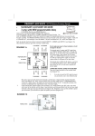
COM-4PD(PCI)H
Ver.2.01
PCI-bus Opto-isolated RS-422A/485
Communication Board
COM-4PD(PCI)H
T his board is external equipment and an interface board of t he
PCI bu s conformit y which performs serial communication of
RS-422 A/485 conformit y .
It has t he serial port of RS-422A/485 c onformit y o f four
channels by one sheet .
By using attached standard COM drive r soft ware [COM
Set up Disk], it c an access a s a Windows or standa rd COM
port for Linux.
Features
- T he serial communication port of RS-42 2A/485 conformity
is carried.
- It is elect rically insulat e d between each channel and
between personal computers.
- It corresponds to a maximum of 921,6 00bp s high -speed
communication.
- T he baud rat e o f each channel can be individ ually set up by
software.
- FIFO buffer of 128 by t es of reception is carried for every
channel 128 by t es of transmission.
- T he bo ard of a maximum of 16 sheet s can be ext ende d, and
a setup t o COM 1-CO M 256 is possible.
- It can be used a s Windows and a standard COM port of
Linux by attached driver software.
- Dat a-c ommunicat ions mode (fu ll-dup lex, half doubl e) can
change a set up by changing a s wit ch.
- The 100Ohm terminator (terminus resistance) required at
the time of p art y l ine (mult i -drop s) co nnect ion i s built in ,
and it can insert in each signal line by c hanging a s wit ch.
- Serge protection of all t he RS-422A/48 5 signal lines is
carried out.
Specification
Item
Number of channels
Interface type
Isolation
Isolation voltage
Transfer method
Baud rate
Data length
Board size
121.69(L)
106.68(H )
Specification
4 channels
RS-422A/RS-485
Channel Isolation/Bus Isolation
Channel Isolation: 500VDC, Bus Isolation: 1000VDC
Asynchronous serial transfer (Full/Half duplex)
1 2
2 to 921,600bps * *
5, 6, 7, 8 bits
1
1, 1.5, 2 stop bits *
1
Parity check
Even, Odd, Non-parity *
Controller chip
162850 or equivalent
(Each channel has 128-byte receive and 128 -byte transmit FIFO
buffers.)
3
Connecting distance
1200m(Typ.) *
4
Interrupt requests
1 level use *
I/O address
Any 32-byte boundary
Power consumption
5VDC 950mA (Max.)
Operating temperature 0 to 50°C, 10 to 90%RH (No condensation)
PCI bus specification
32-bit, 33MHz, 5V
Dimension (mm)
121.69(L) ×106.38(H)
Weight
95g
*1 These items can be set by software.
For the "API Function Library API-PAC(W32)" and the "Standard COM Driver Software COM
Setup Disk" on the supplied CD-ROM, the range is 15 to 921,600 bps.
*2 Data transmission at high speed may not be performed normally depending on the
environment including the type of status of connected material of cable and environment.
*3 The table below lists an example of the relationship between baud rate and communication
distance.
Communication
Baud rate
distance
300m
115,200bps
600m
57,600bps
900m
19,200bps
1200m
9,600bps
Communication cable: 28AWG, double shielded cable, twisted pairs used for each +/- signal
line.
*4 A single interrupt signal "INTA" is output as a collection of interrupt input signals from two
channels.
[mm]
The standard outside dimension (L) is
the distance from the end of the board
to the outer surface of the slot cover.
1
COM-4PD(PCI)H
Support Software
Attached support software
Standard COM driver software COM Setup Disk
It is t he soft wa re for usi ng t he ser ial communicat ion board of
our company like t he COM port (st and ard COM ) o f t he
main part of a personal computer by Win dows or Linux. It
can set up t o C OM 1-COM 256 by ext ension of a b oard.
It is p ossible to perform various se rial communications, such
as rem ot e access service (RA S) and a power supply (UPS)
non-cut t he elect ric current off. I n Windows, it corresp onds
to the standard Win32API communication functions
(CreateFile () and WriteF ile(), ReadFile () and SetCommState
(), et c.) for OS. It corresponds to communication control
(M SComm) of Visual Basic.
In Li nux, it is based on t he st andard type dr iver for O S. It
corresponds t o t he st anda rd funct io n of op en () and clo se(),
read () and write(), etc.
Environment of operat ion
T he main corresp ondences OS Windows X P, 2000, N T , M e,
98, Linux, etc.
Ver.2.01
hardwa re of our company in st andard W in32API funct ion
(DLL) form for Windows. B y t he vari ous progra mming
langua ges which ar e supportin g Win32API funct ions, such as
Visual Basic, and Visual C/C+ +, t he high -speed appli cat ion
soft ware which harnessed t he specia l feature of t he hardware
of our company can be creat ed.
T he newest driver and downloa d service ( ht t p ://www.c ont ec.
co.jp / apip ac/) o f difference file ar e also off ered.
Environment of operat ion
Main c orresp ondence OS Win dows 2000, NT , M e, 9 8, et c
Main a dapt at ion languages Vi sual C++, B orland C++, Visual
Basic, etc.
Ot hers T he hard disk which has 20MB empty domain for
every library software is required.
Note!
- They are the local functions which were original with our
company as for this library, and were defined. (SioOpen
( ) and SioWrite( ), SioRead ( ) and SioStatus( ), etc. ) It
is not compatible with the standard Win32API
communication functions (CreateFile( ) and WriteFile( )
etc.) for OS.
Optional support software
Collec t ion for me asurement syst ems devel opment of Act iveX
component s ACX-PAC (W32)BP
It is t he conveni ent measurem ent syst ems development t ool
for Wi ndows in wh ich t he coll ect ion of examples whi ch can
be use d immediately , and t h e collect ion (collection of
soft wa re part s) of component s which ca n program easily
only b y combining were mentioned.
Component for control of t he input -and-output board (card)
of our company is made t h e one p ackage. Anal og I/O, di git al
I/O, control of each interface of GPIB communication a nd XY graph display , and file preservat i on are possible.
Collection for me asurement syst ems development of Act iveX
component s ACX-PAC (W32)AP
In addit ion to t h e funct ion o f ACX-PAC(W 32)BP,
component s, such as displ ay syst em s, such as various grap h,
swit ch , and lamp , and op erat ion / analysis, serv e as a
package.
When using it by MS-DOS
Please refer t o t h e sample pr ogram for M S-DOS in appending
CD-ROM .
Cable & Connector (Option)
Cable (option)
The distribution cable for COM -4ch boards
(37M -> 9M x 4, 250mm) :
PCE37/9PS
Connector (option)
9pin D -SUB (male ) connect or Five-pie ce set :C N5-D9M
9pin D -SUB (fema le) connector Five-pie ce set :C N5-D9F
37pin D-SUB (mal e) connect or Five-pie ce set :CN 5-D37M
Gratis download service
API Fu nct ion Libr ary API-PA C(W32)
It is the library software which offers the command to the
Packing List
- Board [COM -4PD(PCI)H] - 1
- This User's M anual - 1
- COM Setup Disk(CD-ROM ) - 1
2
COM-4PD(PCI)H
Ver.2.01
External Connection
T he di st ribut ion cable ot her t han t h e met hod o f carrying out a dir ect file f rom t he connector on board can be used f or connection of
COM -4PD (PCI)H and external apparat us.
9pin D-SUB connector distribution cable is used.
Aft er using PCE3 7/9PS of opt ional di st ribut ion cables an d dist ributing t o 9pin D-SUB c onnect or f or four ch annels [M (male)
type], it connec t s wit h external apparatus.
Specification of "PCE37/9PS"
- Cable
9-conductor shielded cable
Cable length : 250mm
Conductor size : AWG#2 8
- Connector used
37-pin D-SUB, male connector
Thumb screw :
UNC #4-40 (inch screw )
CH 1
CH 1
T xD1Tx D1+
RTS1RT S1+
SG1
5
4
3
2
1
9
8
7
6
Rx D1Rx D1+
CT S1+
CT S1-
.
.
.
CH 2
CH 3
CH 4
CH 4
5
4
3
2
1
T xD4Tx D4+
RTS4RT S4+
SG4
9
8
7
6
Rx D4Rx D4+
CT S4+
CT S4-
- Connector used
9-pin D-SUB, male connector
Thumbscrew : UNC#4-40(inch screw)
- Applicable connectors
17JE -13090-02 (D8C) (mfd. by DDK, Female)
Distribution cable (option)
The distribution cable for COM -4ch boards (37M -> 9M x 4, 250mm) PCE37/9PS
Note!
- Each SG of CH 1-4 of option cable is not connected to the shield of option cable. However, the frame of each connector is
connected to the shield. T his means that the shield of option cable is connected to a personal computer case via the fr ame of
inter face connector.
- Moreover, this op tion cable is not a tw isted-pair cable (bala nce line/tw isted-pair line).
It connects directly from the connector on a board.
From t he connect o r on board , when y ou connect wit h ext ernal apparat us direct ly , using optional connector CN5-D37M et c.,
pleas e make a c able himself and connect .
Signal arrangement
Scr ew nut: UN C#4-40(inch screw)
37
19
20
1
- Connector used
37-pin D-SUB , female connector
DCLC-J37SAF -20L9 (mfd. by JAE)equivalent
- Applicable connector
17JE-23370-02(D8C) (mfd. by DDK , Male)
FDCD-37P (mfd. by HIROSE, Male)
DC-37P-N (mfd. by JAE, Male)
CN5-D37M (mfd . by CONTEC, Male) (Five connector set)
CH1
CH1
CH1
CH1
CH2
CH2
CH2
CH2
CH2
CH4
CH4
CH4
CH4
CH3
CH3
CH3
CH3
CH3
Request to Send +
Receiv e Data +
Tr ansmit Data Si gnal Gr ound
Request to Send Cl ear to Send +
Cl ear to Send Tr ansmit Data +
Receiv e Data Request to Send +
Receiv e Data +
Tr ansmit Data Si gnal Gr ound
Request to Send Cl ear to Send +
Cl ear to Send Tr ansmit Data +
Receiv e Data -
RT S1+
RxD 1+
T xD1SG 1
RTS2CT S2+
CTS2TxD 2+
RxD2RT S4+
RxD 4+
T xD4SG 4
RTS3CT S3+
CTS3TxD 3+
RxD3-
37
36
35
34
33
32
31
30
29
28
27
26
25
24
23
22
21
20
19
18
17
16
15
14
13
12
11
10
9
8
7
6
5
4
3
2
1
RTS1CTS1+
CTS1T xD1+
RxD 1RTS2+
RxD 2+
T xD2SG 2
RTS4CTS4+
CTS4T xD4+
RxD 4RTS3+
RxD 3+
T xD3SG 3
N .C.
CH1
CH1
CH1
CH1
CH1
CH2
CH2
CH2
CH2
CH4
CH4
CH4
CH4
CH4
CH3
CH3
CH3
CH3
Request to Send Cl ear to Send +
Cl ear to Send Tr ansmit Data +
Request to Send Request to Send +
Receive Dat a +
Tr ansmit Data Si gnal Gr ound
Request to Send Cl ear to Send +
Cl ear to Send Tr ansmit Data +
Receive Dat a Request to Send +
Receive Dat a +
Tr ansmit Data Si gnal Gr ound
CN1
3
COM-4PD(PCI)H
Ver.2.01
Connection of cable
T he example of connection o f t he cable in t his b oard is shown in t he f ollowing f igure.
Transmission of R S-422A/485 int erface is t he diff erent ial system in which t he rel at ive potent ial difference between 2 lines (+, -)
has a meaning as a signal. In order t o raise opposit e noise nat ure, if p ossibl e, please use a t wist ed-pair cable (balanc e line/ twistedpair l ine).
The example of connection when connecting
RTS and CTS with external apparatus in full
duplex mode
T xD+
TxD +
Tx D-
T xD-
RxD +
RxD+
RxD-
RxD -
RT S+
RTS+
RT S-
RTS-
CT S+
CTS+
CTS-
CT S-
SG
SG
The example of connection in the half-double
mode
T xD+
Tx D+
TxD -
T xD-
SG
SG
External device
Note!
- If it connects by mistaken connection, it will become the
cause of failure of connection apparatus or this board.
External device
The example of connection when carrying out
the self-loop of RTS and CTS in full duplex
mode
TxD +
Tx D+
TxD -
Tx D-
RxD+
RxD+
RxD -
Rx D-
SG
SG
External device
All data subject to change without notice.
4