1
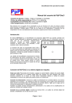
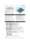
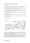
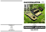
PRODIGY ADVANCE - DCC30 Stationary Accessory Decoder
STATIONARY ACCESSORY DECODER
3 amp with NEW programmable delay
•
•
( CASCADING effect for easy ROUTE operation)
Thank you for choosing the PRODIGY ADVANCE DCC Stationary
Accessory Decoder. This decoder is an NMRA compatible Accessory Decoder. You
must use PRODIGY ADVANCE or other DCC systems that support CV programming and have Accessory Decoder
function capability. The PRODIGY ADVANCE Stationary Accessory Decoder comes with 4 pairs of outputs. Think of it
as 4 Decoders in 1, each having it’s own sub-address. The pairs are labeled as A, B, C and D (see Diagram 1A)
Each sub-decoder has three terminal connectors labeled OUTPUT 1, COMMON and OUTPUT 2 (see Diagram 1A).
These terminal connectors go to the accessory or point motor.
OUTPUT 2
COM
TO ACCESSORY
OUTPUT 1
OUTPUT 2
COM
TO ACCESSORY
OUTPUT 1
DIAGRAM 1a
FROM POWER SUPPLY
16v AC INPUT
CV515
FROM DCC TRACK
CV517
CV516
TO ACCESSORY
2.
OUTPUT 2
COM
OUTPUT 1
This decoder gets it’s power and DCC signal from
your PRODIGY ADVANCE BASE UNIT or through the
track rails. It can also power your accessories from
DCC track power or any external 16v AC power
supply. It is ALWAYS better to power your accessories with an external power supply so your DCC
system utilises its full power to run your trains.
This decoder also rectifies the AC power, so accessories requiring DC current, such as slow motion DC
point motors or LED’s, do not need a separate DC
power supply.
CV518
OUTPUT 2
COM
OUTPUT 1
RED WIRE
Do not apply any power to these terminals as it will
damage the decoder.
CONNECTING YOUR DCC SYSTEM TO THE DECODER
There are 4 input terminals on the decoder board
(see Diagram 1A).
1.
TO ACCESSORY
If you do not want the DCC signal to power
any accessories, run 2 wires between your
DCC unit or your track rails closest to the decoder, and the lower 2 input terminals marked “from DCC
track” (see Diagram 1A). Then, using an external 16v AC power supply (such as a GAUGEMASTER M1),
connect its 2 output wires to the upper two input terminals marked 16v AC. The quantity and type of accessories will determine the requirements of your 16v power supply.
If you want the DCC signal to power your accessories, run 2 wires between your DCC unit or your track
rails closest to the decoder, and the lower 2 input terminals, and then jump them from the two lower input
terminals to the upper two input terminals (see Diagram 1B). Remember, if you use this method to power
your accessories, you will have less power to operate your trains (Diagram 1B)
DIAGRAM 1b
RED WIRE
FROM DCC TRACK
CONNECTING YOUR ACCESSORY DECODER TO A SLOW MOTION POINT MOTOR (DC)
(DIAGRAM 3) or SIGNAL LED’s (DC) (DIAGRAM 4)
Your accessory decoder rectifies the AC input so an auxiliary DC power supply is not needed, just an AC power supply can be used for DC accessories. Follow Diagram 3 for each pair of the 4 outputs (A-B-C-D).
Ten 300 ohm resistors are included with the decoder for use with slow motion point motors or signal LED’s.
Use resistors to connect signal LED’s (not included) to the four pairs of outputs (A-B-C-D) of your accessory
USING LED’s AND SLOW MOTION POINT MOTOR FROM SAME DECODER PAIRS OF OUTPUT
(A-B-C-D) (DIAGRAM 5)
A simple combination of diagram 3 and 4,
PROGRAMMING THE DECODER
This decoder has the following CV’s
CV513 - main address that is a 2 digit (1-127) address
CV515 - The output mode of Pair A (sub-decoder A)
CV516 - The output mode of Pair B (sub-decoder B)
CV517 - The output mode of Pair C (sub-decoder C)
CV518 - The output mode of Pair D (sub-decoder D)
If your DCC system cannot program CV513 to CV518, you can use CV1 to CV6 to program the decoder on the
Program Track. The CV mapping is as follows
CV1 = CV513 = main address
CV3 = CV515 = pair A output mode
CV4 = CV516 = pair B output mode
CV5 = CV517 = pair C output mode
CV6 = CV518 = pair D output mode
PROGRAMMING
During the programming mode, you cannot program reverse polarity into the accessory decoder. You can only reverse the polarity of a specific output when you program a route for your accessory decoders on your DCC system
PROGRAMMING ADDRESS CV513
The main address can only be programmed on the Program Track. This main address, once programmed, automatically assigns the four outputs their sub-addresses, so you need only to program one address to the decoder. Your
decoder’s main address is pre-programmed to #1 at the factory. So the sub-addresses are 1,2,3 and 4..
If you have a second decoder, you can use the CV program mode to program its main address CV513 to #5. So the
second decoder’s sub-addresses will be 5, 6, 7 and 8. If you have a third decoder, you can program its main address
CV513 to #9. So the third decoder’s sub-addresses will be 9, 10, 11 and 12. Always program the main address to
1, 5, 9, 13, 17, 21…
PROGRAMMING OUTPUT MODE CV515, CV516, CV517 and CV518
Each pair of the outputs can be set to 3 different types of output mode as follows
1.
Steady ON, or steady OFF, (Latching) for slow motion, point motors or lights in buildings
2.
Momentary ON/OFF for twin coil type point motors
3.
Alternating flashing (with variable flash rates) such as those at level crossings.
Example 1:
To set pair A outputs to control a slow motion point motor (latching) or to turn lights in buildings ON or OFF, program
CV515 to a value of either 0 or 128. CV515 is for Pair A
Example 2:
To set pair B output to control a twin coil point motor momentarily, program CV516 a value from 1 to 127, with 1 as
the minimum turn-on time (0.1 second) and 127 as the maximum turn-on time (12.7 seconds). Here CV516 is for
pair B. The amount of time the output is ON is equal to 0.1 times the number you program into the CV, but it will
work for the other 3 outputs as well.
Example 3:
To set pair C outputs to alternating flash for a pair of level crossing lights, program CV517 to a value between 129 to
255. The flash rate is equal to 0.1 x (N –128), where N is the value programmed into CV517. For example, when
N=129, the flash rate is 0.1 second [0.1x(129-128)]. When N=133, the flash rate is 0.5 seconds [0.1x(133-128)].
PTO.
CONNECTING YOUR ACCESSORY DECODER TO TWIN COIL (AC) POINT MOTORS
Your accessory decoder comes from the factory pre-programmed to operate in latching mode, “Constant On”.
However, twin coil point motors use a momentary pulse to activate them. If left in the “Constant On” output, the
decoder will burn out the point motors. Please re-program the accessory decoder to operate the twin coil point
motors prior to connecting them to the accessory decoder. See the section on programming your decoder.
If you are going to use the Accessory Decoder solely for twin-coil point motors, cutting the red wire will
automatically set the decoder for use of this type of point motor. If this does not work please reprogram the outputs
as per example 2. See the section on programming and Diagram 2.
Make sure the common wire is connected to the COM terminal (Diagram 1)
DIAGRAM 2
CV515
CV516
CUT THIS RED WIRE IF THE DECODER
IS USED ONLY FOR TWIN COIL POINT
MOTORS
RED WIRE
FROM 16v AC POWER SUPPLY
CV517
CV518
FROM DCC TRACK
DIAGRAM 3
DIAGRAM 4
FROM 16v AC POWER SUPPLY
FROM 16v AC POWER SUPPLY
RED WIRE
FROM DCC TRACK
RED WIRE
FROM DCC TRACK
SLOW MOTION
POINT MOTOR
LED1
LED2
DIAGRAM 5
FROM 16v AC POWER SUPPLY
FROM DCC TRACK
CV515
CV517
CV516
RED WIRE
CV518
SLOW MOTION
POINT MOTOR
LED1
LED2
Caution:
With stiff or difficult to activate turnouts operated with twin coil point motors (larger scales) you may have to adjust
the input value to a higher number to get the turnout points to activate properly. Starting at a minimum value of 1,
go up one value at a time until the turnout activates properly. Starting or going up with too high a value may cause
the twin coil point motor to overheat and burn out.
PROGRAMMING ON THE MAIN TRACK (OPS MODE PROGRAMMING)
To program the decoder on your main track, you need to know its main address. Treat the accessory decoder as a
loco decoder and perform CV program on main. You can only program CV515, CV516, CV517 and CV518 on the
main track.
OPERATION WITH PRODIGY ADVANCE
Press Accy button. “Accy” will display. Enter the decoder sub-address and then press Enter. “1 or 2” will display.
To turn on the output, press 1. To turn off the output, press 2.
PROGRAMING A TIME DELAY
This unit can be programmed to give individual delays on all outputs which is commonly used on route settings or
any item that will benefit from a cascading effect. The default delay is 0 but it can be reprogrammed from 1 to 30
whish is approximately 0.1 to 3 seconds. The CV mapping is as follows but always use the 3 digit address if possible.
CV51 = CV563 = DELAY (output A)
CV52 = CV564 = DELAY (output B)
CV53 = CV565 = DELAY (output C)
CV54 = CV566 = DELAY (output D)
A typical example for 2 accessory decoders being programmed on the main track is shown below.
Loco=1 CV=563 Data=1
Loco=2 CV=563 Data=17
“
“ CV=564 Data=5
“
“ CV=564 Data=21
“
“ CV=565 Data=9
“
“ CV=565 Data=25
“
“ CV=566 Data=13
“
“ CV=566 Data=29
Remember “Loco” represents the primary decoder number and is not required on the programming track.
ROUTES
Consult your PRODIGY ADVANCE User Manual for setting and operating routes.
When setting a route into motion by turning it on, make sure the power supply that is powering your accessories can
handle the load generated by the number of accessories being activated at the same time. If you use DCC to power
the twin coil point motors, the DCC system may experience short circuit protection due to high current surge.
WARRANTY AND REPAIR
If you would like a copy of the PRODIGY ADVANCE user manual, please send us a SAE at the
address shown below. This document is also downloadable from our website (which also has
a wealth of technical information) at www.gaugemaster.com
If you believe your decoder is faulty, please telephone us in the first instance. We will advise
you of your best course of action. If it involves sending anything back, please send it to the
address below via insured post and packed securely.
POSTAL ADDRESS
OTHER USEFUL CONTACT NUMBERS
Technical Department
GAUGEMASTER Controls Plc
Gaugemaster House
Ford Road, Arundel
West Sussex
BN18 0BN
Telephone - 01903 884321
Shop Sales - 01903 884488
Fax - 01903 884377
E Mail - [email protected]
GAUGEMASTER - The UK Home of Prodigy Advance