1
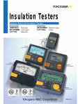
Insulation Testers
Earth Testers
Insulation and Earth Testers
Insulation Tester
Earth Tester
Single range
2 and 3 ranges
Single range
4 ranges
NEW
Digital
Analog
EY200
MY40
Bulletin MY-E
What Is Insulation Resistance?
Test Methods for Low-voltage Circuits
Insulation resistance represents the state of insulation of electric equipment
or circuits. It is one of the important measurement parameters in terms of
safety and security. Methods of examining the state of insulation include using a clamp-on leakage tester for live circuits. Under normal circumstances,
however, such electric equipment or circuits are shut down temporarily and
their insulation is tested with an insulation tester.
Insulation resistance between cables of a low-voltage circuit and between
the circuit and ground is tested for each circuit that can be separated by a
switch or overcurrent breaker installed as specified by the electrotechnical
equipment standards.
The low-voltage circuit is shut down by opening the switch and insulation between cables of the circuit and between the circuit and ground is tested. If the
measured value is below the rated resistance, all shunt switches of a trunk
line are opened and insulation is tested separately for each shunt circuit.
The comparator function of the MY40 insulation tester allows for smooth
judgment when checking the insulation of electric circuits.
Classification of Applications
Applications are roughly classified into low-voltage, high-voltage and ultrahigh-voltage circuits. The table below summarizes examples of using rated
test voltages. A tester with the rated test voltage of 500 V or 100 V/250 V is
used for low-voltage circuits.
Rated test
voltage
25V
50V
100 V
125 V
250 V
500 V
1000 V
General Electric
Electric Installations/Circuits
Equipment
Insulation testing at
safe voltage levels
Insulation testing of telephone line cirInsulation testing of
cuits
telephone network
equipment and flameproof equipment
Insulation testing for maintaining lowInsulation testing of
voltage circuits or equipment handling
control equipment
levels lower than 100 V
Insulation testing of
Insulation testing for maintaining lowlow-voltage circuits or voltage circuits or equipment handling
equipment
200 V or lower levels lower than 100 V
Insulation testing of
Insulation testing for maintaining lownewly installed circuits voltage circuits or equipment handling
or of circuits or equip- levels lower than 600 V; insulation testment handling levels ing of circuits or equipment handling
lower than 600 V
100 V, 200 V, or 400 V levels upon
(general equipment) completion of installation
Insulation testing of circuits or equipInsulation testing of
ment handling constantly high operatcircuits, equipment,
ing voltages (e.g., high-tension cables,
or facilities handling
high-voltage electric equipment, and
levels higher than 600
communications equipment and elecV (general equipment)
tric circuits handling high voltages)
Insulation Testers
Display readings
Rated test voltage: 25 V
Maximum effective reading: 5 MΩ
1
= Central scale value
= First effective measuring range
= Second effective measuring
range
0.2
0.5
2
∞
0.1
0.05
0.02
0.01
0.0
05
5
0
Maximum effective reading:
The maximum reading that is indicated on the insulation tester and falls within the range with which the accuracy of the insulation tester is guaranteed.
Effective test range:
A test range or ranges, among those of the insulation tester, over which
accuracy specified in the standards is guaranteed. In moving-pointer insulation testers, the range from a resistance value one-thousandth (1/1000)
the maximum effective reading to the resistance value that is nearest to
half (1/2) the maximum effective reading and equal to the maximum effective reading multiplied by 1, 2 or 5 or by any of these values multiplied by
ten (10) raised to a whole-number power, shall be referred to as a first effective measuring range. In addition, the range from the upper limit of the
first effective measuring range to the maximum effective reading and the
range from the lower limit of the first effective measuring range to the zero
(0) reading shall be referred to as second effective measuring ranges (see
the figure above). In digital insulation testers, the first and second effective
measuring ranges shall be those indicated on the insulation tester (Excerpt
from JIS C1302-2002).
General Specifications
Digital
Applicable standard
Model
Methods of Scaling the 1st and 2nd Effective Measuring Ranges of
Moving-pointer Insulation Testers
Analog
JIS C 1302
MY40
3213A
MY10, 2406E
A change in the reading must not exceed ±10% when a resistance calculated from the Same as to the left, except that the conEffect of
rated measuring voltage and current is connected to the tester and a capacitance of 5
nected resistance has the central scale
AC components
mF ±10% is connected in parallel across the resistance.
value.
A change in the reading at an ambient tem- A change in the reading must not exceed
A change in the reading at an ambient
perature of 23°C must not exceed ±5% at ±5% at the central scale value and be no
temperature of 23°C must not exceed
±2% at each of the maximum, minimum,
the central scale value and be no more than more than ±0.7% of the scale length at eiEffect of temperature and central scale values of the first effective ±0.7% of the scale length at either the infi- ther the infinite scale value or the zero scale
measuring range when the temperature is nite scale value or the zero scale value when value when the temperature is changed
changed from 23°C to 0°C or to 40°C.
the temperature is changed from 23°C to 0° from 20°C to 0°C or to 40°C.
C or to 40°C.
A change in the reading must be within the specified tolerance range when the tester is left to stand for one hour under a relative huEffect of humidity
midity of 90%.
A change in the reading must not exceed ±3% (analog) and be no more than ±1.2%
Same as to the left, except that a change at
Effect of external
(digital) at each of the maximum, minimum, and central scale values of the first effective the central scale value must be read.
magnetic field
measuring range when an external magnetic field of 400 A/m DC is applied to the direction where the effect thereof is the most significant.
A change in the infinite scale value (∞)
A change in the infinite scale value (∞)
must not exceed ±2% of the scale length
must not exceed ±2% of the scale length
when the tester is inclined 30° forward or
when the tester is inclined 90° forward or
backward and leftward or rightward from
backward and leftward or rightward from
Effect of inclination
the horizontal position.
the horizontal position. Also, a change in
the reading must not exceed ±15% at each
of the maximum, minimum, and central
scale values of
No damage should be present when a 50 Hz or 60 Hz AC voltage with an amplitude 1.2 Same as to the left, except that the voltage
Effect of external
times the rated test range is applied across the test terminals for 10 seconds each time is applied for 10 seconds with the tester
voltage application
the tester switch is turned ON and OFF. Nor should the user be subjected to any danger. switch turned OFF.
No structural damage should be present and a change in the reading must be within
No mechanical or electrical damage should
the specified tolerance after applying a vibration frequency of 25 Hz and a displacement be present and the rating within the speciamplitude width of 1 mm for 20 minutes to each of three axis directions.
fied tolerance must be satisfied after applyEffect of vibration
ing a vibration frequency of 16.7 Hz and a
double amplitude of 4 mm for one hour to
each of three axis directions.
No structural damage should be present and a change in the reading must be within the The rating within the specified tolerance
specified tolerance after directly and reversely applying 1000 m/s2, 6 ms half sine-wave must be satisfied after applying a shock of
Effect of shock
shocks to the three axis directions three times each (i.e., 18 times in total).
1000 m/s2 to each of three directions twice
each.
Operating temperature/ 0°C to 40°C/90% RH maximum (no condensation)
humidity range
Storage temperature/ -10°C to 60°C/70% RH maximum (no condensation – batteries should be removed)
humidity range
1
Points on How to Choose an Insulation Tester
Type
Ratings
Functionality
Accessories
Two choices:
Choose an analog model if
visual recognition is of utmost
importance, or a digital model
if precise numeric recognition
is of utmost importance.
A wide choice of voltage/resistance
ratings, from 25 V/5 MΩ to 1000
V/2000 MΩ
Some models have two or three ranges; thus, you need not take more
than one instrument to the site.
Each series includes a model
or models with a backlight for
working in dark places. Multifunctional models capable of,
for example, AC voltage measurement, are also available.
Optional test probes and
probe tips are available for a
variety of test environments.
Selection Guide (Insulation Tester & Earth Tester)
Type
Digital insulation
testers
4
ranges
Series/
Model
Suffix Code
& Backlight
MY40
01 (EL-illuminated)
*
31 (N/A)
Rating
125V/200MΩ
250V/200MΩ
500V/2000MΩ
1000V/2000MΩ
2&3
ranges
125V/20MΩ
42 (EL-illuminated)
250V/50MΩ
33 (N/A)
125V/20MΩ
34 (N/A)
Analog insulation testers
35 (N/A)
Single
range
Single
range
Type
MY10
3213A
*
0–300V
0–600V
0–600V
1000V/2000MΩ
03 (afterglow-illuminated) 500V/100MΩ
0–500V
04 (afterglow-illuminated) 500V/1000MΩ
0–500V
05 (afterglow-illuminated) 1000V/2000MΩ
0–500V
41 (N/A)
100V/20MΩ
0–150V
42 (N/A)
250V/50MΩ
0–250V
43 (N/A)
500V/100MΩ
0–300V
44 (N/A)
500V/1000MΩ
0–300V
45 (N/A)
1000V/2000MΩ
0–300V
46 (N/A)
125V/20MΩ
0–250V
Rating
Analog
Analog
Automatic discharge
P.5
Battery check
Battery check
AC Voltage
Display Additional Function
Measuring range
P.5
External View
Page
Earth Voltage 3 1/2-digit
0–2000Ω
P.6
Earth Testers
0–200V
*
P.4
Battery check
250V/500MΩ
0–300V
323511
Automatic discharge
0–600V
0–250V
EY200
Analog
1000V/2000MΩ
02 (afterglow-illuminated) 250V/50MΩ
Suffix Code
& Backlight
P.3
Comparator function
Memory function
01 (afterglow-illuminated) 125V/20MΩ
Series/
Model
LCD
Conductor resistance
measurement
250V/50MΩ
500V/1000MΩ
45 (EL-illuminated)
0–600V
500V/100MΩ
500V/100MΩ
44 (EL-illuminated)
Automatic discharge
3 1/2-digit
0–300V
250V/50MΩ
43 (EL-illuminated)
Page
125V/20MΩ
32 (N/A)
2406E
External View
25V/5MΩ
50V/10MΩ
41 (EL-illuminated)
AC Voltage
Display Additional Function
Measuring range
LCD
Earth Voltage
0–1000Ω
Analog
0–30V
* JIS mark has changed from 2008
2
P.6
MY40 Digital Insulation Tester
SERIES
쎲 Digital model with 4 voltage/resistance ratings
쎲 Multifunction
Insulation resistance, AC voltage and conductor resistance measurement
Insulation test mode: Comparator, memory, auto-hold and
discharge functions
All test modes:
Live-line alarm (excluding AC voltage
measurement), battery check and automatic power-off
쎲 Easy-to-view, fluctuation-free display
쎲 Double-action safety mechanism
Protection against inadvertent setting of rotary
switch to 1000 V rating
Testing Performance Specifications
Model
Rating
125V/200MΩ
250V/200MΩ
MY40
-01
500V/2000MΩ
1000V/2000MΩ
Range
Option
.4000
4.000
40.00
200.0
.4000
4.000
40.00
200.0
4.000
40.00
400.0
2000
4.000
40.00
400.0
2000
Resolution Measuring Range
.1kΩ
1kΩ
10kΩ
100kΩ
.1kΩ
1kΩ
10kΩ
100kΩ
1kΩ
10kΩ
100kΩ
1MΩ
1kΩ
10kΩ
100kΩ
1MΩ
Tolerance
Lower Limit of Rated Central Scale
measured Ω Current Value
0.125MΩ
1mA 5MΩ
0–.0199MΩ
.0200–10.00MΩ *
10.01–200.0MΩ
± (5%of rdg+6dgt)
± (2%of rdg+6dgt)
± 5%of rdg
0–.0499MΩ
.0500–20.00MΩ *
20.01–200.0MΩ
± (5%of rdg+6dgt)
± (2%of rdg+6dgt)
± 5%of rdg
0.25MΩ
0–0.999MΩ
1.000–500MΩ *
501–2000MΩ
± (5%of rdg+6dgt)
± (2%of rdg+6dgt)
± 5%of rdg
0.5MΩ
± (5%of rdg+6dgt)
± (2%of rdg+6dgt)
± 5%of rdg
2MΩ
0–1.999MΩ
2.000–1000MΩ *
1001–2000MΩ
Standard test conditions
Ambient temperature/humidity ranges: 23 ±5:/45-75% RH
Tolerances under the above-mentioned conditions:
Deviation from zero scale value: 6 digits maximum
Indication of ∞ mark on bar graph: Approx. 4000 MΩ min. (500 V/1000 V)
Approx. 400 MΩ min. (125 V/250 V)
Open circuit voltage: 130% max. of rated voltage
1mA
5MΩ
1mA 50MΩ
Rated measuring current: 1 mA (0 to 20%) when in first effective measuring range
Short-circuit Current: 2 mA max.
AC voltage measurement (45-400 Hz)
Model
Range Resolution
MY40-01 600V
0.5mA 50MΩ
1V
Accuracy
Input Impedance
±(2% of rdg + 6dgt)
Approx. 2 MΩ
Conductor resistance measurement
Model
Range Resolution
MY40-01 400Ω
Accuracy
±(2% of rdg + 8dgt)
0.1Ω
Open-circuit Voltage
Buzzer sound
resistance: <40Ω.
* First effective measuring range; ** The minimum value at which the rated voltage can be maintained
General Specifications
Standard Accessories
Display: 3 1/2-digit LCD; 4000 count; backlight-illuminated; logarithmic
bar graph; extension bar graph–no fluctuations, as the display shows
the digits of a reading in the order in which each digit settles.
Example of Extension Bar Indicator View
The data value is
changing.
Product
Part Number
Qty
Protection cover
93013
1
Shoulder strap
99005
1
Line probe
98001
1
Earth probe
98002
1
User's manual
–
1
Batteries
–
4
The data value is fixed.
External Dimensions
Unit: mm
52.5
125
103
Comparator function:The MY40 alerts you by turning on the LOW
symbol and sounding the buzzer if the measured value is smaller than
the reference value. You can allocate as many as three user-defined
reference values to each rating. The factory-set defaults are 0.1 MΩ,
0.2 MΩ and 0.4 MΩ.
Memory function:For each rating, you can save as many as 20 measurements at desired memory address numbers.
INSULATION
TESTER
LIGHT
Enter
ALARM
1000V
2000MΩ
500V
MEM
250V
MEAS
200MΩ
PULL LOCK
125V
V
600V MAX
Automatic discharge function:The MY40 automatically begins discharge when you turn off the MEAS switch. You can monitor the state
of discharge by checking the bar graph and make sure discharge is
complete by checking that the segment bar disappear.
COMP
Select
OFF
Clr
1000V RELEASE
High-voltage indicators: The high-voltage symbol and LED lamp
come on to alert you when the MY40 is in insulation testing mode or if
any voltage remains to be discharged.
Live-line alarm:If you apply an AC voltage of approximately 40 V or
higher across the input terminals, the MY40 alerts you by blinking the
LED lamp and sounding the buzzer.
Overrange input alarm: If the voltage being measured exceeds 600 V
during AC voltage measurement, the MY40 alerts you by flashing the
Maximum Value indicator and sounding the buzzer.
93013
Protection cover
Auto-hold function: The tester retains the measured resistance for
approximately 5 seconds after the MEAS switch is turned off.
Dimensions: 125 (W) ҂ 103 (H) ҂ 53 (D) (mm), excluding protrusions
Weight: 420 g (main unit and batteries only, excluding accessories)
Batteries: Four AA (R6P) batteries
Note: See the list of accessories on the backside of this bulletin for more information on
accessories.
3
B9108XA
Accessory-housing case
93015
Carrying case
(case for housing both the main
unit and accessories)
2406E Series of Analog Insulation Testers
SERIES
240631 240632 240633 240634 240635 240641
240642 240643 240644 240645
쎲 Analog models with two and three ratings
쎲 AC voltage measurement
쎲 Automatic discharge
쎲 Sky blue EL backlight
Testing Performance Specifications
Suffix
Code
-E
240631
-E
240641
Model
240632
240642
240633
240643
-E
-E
-E
-E
240634
240644
-E
-E
240635
240645
-E
-E
EL-backlit
Effective
Central
AC Voltage Lower limit of
Rated Current
Measuring range Scale Value Measuring range measured Ω
0.001–5MΩ
0.1MΩ
0–300V
25V/5MΩ
1mA
0.025MΩ
0.2MΩ
50V/10MΩ 0.005–10MΩ
1mA
0.05MΩ
0.01–20MΩ
0.5MΩ
125V/20MΩ
1mA
0.125MΩ
0.01–20MΩ
0.5MΩ
0–300V
125V/20MΩ
1mA
0.125MΩ
0.01–50MΩ
1MΩ
250V/50MΩ
1mA
0.25MΩ
0.01–20MΩ
0.5MΩ
0–600V
125V/20MΩ
1mA
0.125MΩ
0.01–50MΩ
1MΩ
250V/50MΩ
1mA
0.25MΩ
2MΩ
500V/100MΩ 0.05–100MΩ
1mA
0.5MΩ
0.01–50MΩ
1MΩ
0–600V
250V/50MΩ
1mA
0.25MΩ
2MΩ
500V/100MΩ 0.05–100MΩ
1mA
0.5MΩ
1–2000MΩ
50MΩ
1000V/2000MΩ
1mA**
1MΩ
0.1–500MΩ
10MΩ
0–600V
250V/500MΩ
1mA**
0.25MΩ
20MΩ
500V/1000MΩ 0.5–1000MΩ
1mA**
0.5MΩ
1–2000MΩ
50MΩ
1000V/2000MΩ
1mA**
1MΩ
Non-backlit * The minimum value at which the rated voltage can be maintained;
** 0.55 mA in the case of the first effective measuring range
Rating
General Specifications
Standard test conditions:
Ambient temperature/humidity ranges: 23 ±5:/45-75% RH
Position of use: Horizontal (5° max. of angle of inclination)
External magnetic fields: None
Battery voltage: Within effective voltage range
(The pointer must stay within the range indicated by the BAT symbol
when the battery check is performed.)
Tolerances under the above-mentioned conditions:
Resistance measurement: First effective measuring range = ±5% of reading
Second effective measuring range = ±10% of reading
Infinite and zero scale values: 0.7% max. of scale length
AC voltage: ±10% of maximum scale value
No-load voltage: 130% max. of rated voltage
Rated measuring current: 1 mA (0 to 20%) when in first effective measuring range
Short-circuit current: 12 mA max.
External Dimensions
Scale length: Approx. 86 mm (outer scale)
Unit: mm
120
53
Discharge function: The tester automatically begins discharge when you turn off the
MEAS switch. The pointer swings if there is any residual voltage in the circuit under test.
You can make sure discharge is complete by checking that the pointer swings back to
the infinite (∞) scale value. Under this condition, the tester is ready to enter voltage
measurement mode.
110
AC voltage measurement: AC voltage measurement is possible wherever the rotary
switch is positioned.
Dimensions (main unit): Approx. 120 (W) ҂ 110 (H) ҂ 60 (D) (mm)
Weight: Approx. 500 g (including batteries)
Batteries: Six AA (R6P) batteries
Accessories: See the list of accessories on the backside of this bulletin for information
on accessories.
B9108XA
Accessory-housing case
Standard Accessories
Product
Part Number
Qty
98007
1
Earth probe(blake);approx. 1m long
Line probe(vermilion);approx. 1m long
Carrying case
B9075MU
1
w/probe-housing
pocket and neck strap
User's manual
–
1
–
Batteries
–
6
–
Earth and Line probes
Remarks
4
B9705MU
Hard case
7
MY10 Series of Analog Insulation Testers
SERIES
쎲 Analog models with single rating
MY10-01:125V/20MΩ
MY10-02:250V/50MΩ
MY10-03:500V/100MΩ
MY10-04:500V/1000MΩ
MY10-05:1000V/2000MΩ
쎲 AC voltage measurement
쎲 Automatic discharge
쎲 A wide choice of accessories
–Designed for shared use with the MY40
Testing Performance Specifications
Model
Rating
MY10-01
MY10-02
MY10-03
MY10-04
MY10-05
125V/20MΩ
250V/50MΩ
500V/100MΩ
500V/1000MΩ
1000V/2000MΩ
Standard Accessories
Effective
Measuring Range
0.01–20MΩ
0.01–50MΩ
0.05–100MΩ
0.5–1000MΩ
1–2000MΩ
Central Scale
Value
0.5MΩ
1MΩ
2MΩ
20MΩ
50MΩ
Standard test conditions:
Ambient temperature/humidity ranges:
23 ±5:/45-75% RH
Position of use:
Horizontal (5° max. of angle of inclination)
Effect of geomagnetism: None
Battery voltage: Within effective voltage range
(The pointer must stay within the range indicated by the
BAT symbol when the battery check is performed.)
AC Voltage
Measuring Range
0–250V
0–300V
0–500V
0–500V
0–500V
Product
Part Number
Qty
Lower Limit of
Rated Current
Measured Ω*
1
93013
Protection cover
1–1.2mA
0.125MΩ
1
99005
Shoulder strap
1–1.2mA
0.25MΩ
1
98001
Line probe
1–1.2mA
0.5MΩ
1
98002
Earth probe
0.5–0.6mA
1MΩ
1
–
User's manual
0.5–0.6mA
2MΩ
4
–
Batteries
* The minimum value at which the rated voltage can be maintained
Tolerances under the above-mentioned conditions:
General Specifications
Resistance measurement:
First effective measuring range = ±5% of reading
Scale length: Approx. 78 mm
Second effective measuring range = ±10% of reading
Battery life: Approx. 10 hours when continuously operated on
Infinite and zero scale values: 0.7% max. of scale length
manganese-oxide batteries with the pointer pointAC voltage: ±10% of maximum scale value
ing to the central scalevalue.
No-load voltage: 130% max. of rated voltage
Batteries:
Four
AA(R6P) batteries
Rated measuring current:
Dimensions: Approx. 125(w) ҂ 103(H) ҂ 53(D) mm, excluding protrusions
1 mA (0 to 20%) when in first effective measuring
range
Weight: Approx. 400 g (main unit and batteries only, excluding accessories)
Short-circuit current: 12 mA max.
Compliance: EN61010: 1993; EN61010-2-31: 1995 (over voltage category III, pollution Degree2 installations for indoor use).
3213A Series of Analog Insulation Testers
SERIES
쎲 Analog models with single rating
쎲 AC voltage measurement and check live
lines such as motive power lines
쎲 One-touch operation Press-and-lock switch for
continuous measurement
쎲 A wide choice of accessories to meet various
testing requirements
쎲 Vibration- and shock-resistant hand-held
compact testers
General Specifications
Testing Performance Specifications
AC Voltage
Effective
Central
Lower Limit of Rated
Measuring Range Scale Value Measuring Range measured Ω
Current
321341
0.02–20MΩ
0.5MΩ
0–150V
100V/20MΩ
1mA
0.1MΩ
321342
0.05–50MΩ
1MΩ
0–250V
250V/50MΩ
1mA
0.25MΩ
321343
0.1–100MΩ
2MΩ
0–300V
500V/100MΩ
1mA
0.5MΩ
321344
1–1000MΩ
20MΩ
0–300V
500V/1000MΩ
1mA**
0.5MΩ
321345 1000V/2000MΩ
2–2000MΩ
50MΩ
0–300V
1mA**
1MΩ
* The minimum value at which the rated voltage can be maintained; ** 0.55 mA in the case of the first effective measuring range
Model
Rating
Standard test conditions:
Ambient temperature/humidity ranges:
23 ±5:/45-75% RH
Position of use:
Horizontal (5° max. of angle of inclination)
Effect of geomagnetism: None
Battery voltage: Within effective voltage range
(The pointer must stay within the range indicated by
the BAT symbol when the battery check is performed.)
Tolerances under the above-mentioned conditions:
Resistance measurement:
First effective measuring range = ±5% of reading
Second effective measuring range = ±10% of reading
Infinite and zero scale values: 0.7% max. of scale length
AC voltage: ±10% of maximum scale value
Open circuit voltage: 130% max. of rated voltage
Rated measuring current:
1 mA (0 to 20%) when in first effective measuring range
Short-circuit current: 12 mA max.
5
Scale length: Approx. 88 mm
Dimensions (main unit): Approx. 110 (W) ҂ 180 (H) ҂ 60 (D) (mm)
Weight: Approx. 700 g including batteries, or approx. 1.2 kg including hard case, handle, test leads and batteries
Batteries: Eight AA (R6P) batteries
Accessories: See the list of accessories on the backside of this
bulletin for information on accessories such as
probes with a switch.
Standard Accessories
Product
Part Number
Qty
Test lead
Hard case
Handle
User's manual
Batteries
98050
B9600HA
B9303XE
–
–
1 (consist of earth/line terminal)
1 (w/leads-housing case)
1
1
8
NEW
Digital Earth Tester EY200
Specifications
3-pole earth resistance measurement (precise measurement)
Connect the earth/ground electrode (E) and auxiliary spikes (P, C) to the
main body using the accessory test lead. Put apart 5 to 10 m between E
and P, and P and C, respectively. E, P, and C should be approximately in a
line.
Yellow
Red
Green
• Model Code
Name
Model
Digital Earth Tester
EY200
Earth/Ground electrode
under test
2-pole earth resistance measurement (simplified measurement)
• EY200 General Specifications
Name
Model
Display
LCD Digital Display:1999-count digital reading
Measuring Range
Earth Resistance: 2000Ω LSD:0.01 to 1Ω
Earth Voltage: 200V
Accuracy
Earth Resistance: 20Ω range: ±2%rdg±0.1Ω
200Ω range: ±2%rdg±3dgt
2000Ω range: ±2%rdg±3dgt
Earth Voltage:
±1%rdg±4dgt
A simplified 2-pole measuring method can be used if there is an almost
perfectly earth/ground object such as a lead or iron water-pipe (plastic
pipes cannot be used) or if there is an object with a known value of earth
resistance, near the measurement site.
Approx. 3mA (at 20Ω range)
Battery Life
Approx. 4.5hours (at 5 second measuring 3300
times)
Operating Temp.
and Humidity
0~40°C, 85%Rh or less
Dimensions
Approx. 105×158×70mm
Weight
Approx. 550g
Standard
Accessories
3-pole Test Lead (Model 98074),
Earth Spikes (for EY200) (Model 98070),
2-pole Test Lead Set (Model 98075),
Soft Case (Model 93041),
Shoulder Belt (for EY200) (Model 99018),
Six AA (R6) dry cells,
User’s manual
Red
Re
(indicated value)
Green
Measuring Frequency Approx. 820Hz
Measuring Current
Auxiliary spikes
Earthed electrode
under test
Secondary side Primary side
Power-supply transformer
Be sure to connect to
the earth/ground side
of the commercial
power supply.
When the earthing of a commercial power supply is used
Re=Rx+re
Analog Earth Tester
SERIES
쎲 3 terminal measurement of earth resistance
쎲 Accurate, wide-range logarithmic scale
쎲 AC potentiometer bridge, synchronous detector
쎲 Portable yet rugged and shockproof
General Specifications
Measuring Range:
Earth Resistance: 0 to 10 to 100 to 1,000 Ω
Earth Voltage: 0 to 30 V
Ambient Temperature Influence: Variation in indication is within the corresponding one
scale division for temperature change by 20±20:.
Battery Voltage Influence: The accuracy is maintained wihtin the specified limit even if
the voltage decreases down to approx. 4 V under operating condition.
Scale:
Earth Resistance: 3-digit logarithmic continuous scale on measuring dial
Earth Voltage: Uniform scale on galvanometer
Earth Voltage Influence: Variation in indication is within the corresponding one scale
division for the earth voltages of up to 10 V at commercial frequency.
Accuracy:
Earth Resistance: ±5% of 2 Ω in the range of 0 to 2 Ω
±2.5% of 20 Ω in the range of 2 to 20 Ω
±2.5% of 200 Ω in the range of 20 to 200 Ω
±5% of 1,000 Ω in the range of 200 to 1,000 Ω
Earth Voltage: ±5% of full scale value
Power Source: Four 1.5 V batteries
Insulation Resistance: More than 20 MΩ at 500 V DC between terminals and case
Dimensions: Approx. 122 ҂ 190 ҂ 124 mm not including accessories.
Weight: Approx. 1.5 kg for Instrument only.
Approx. 3.5 kg including all accessories.
Measuring Frequency: 500 Hz
6
Insulation Testers
Quick-reference Table of Accessories
3213A
2406E
For breaker pins
–
–
99011
General-purpose
B9600GN
–
–
Extended
B9600NX
–
–
Sharp-pointed
B9600NZ
–
–
–
98001
Series/Model
Spare
probe tip
Line probe
Measuring Lead unit (Paired earth/line terminals)
–
98050
–
–
–
–
98052
Replaceable type Line Probe
Case
*1
98002
Bag for housing spare probe tips
B9600NV
–
–
Accessory-housing case
B9646CA
B9108XA
B9075MU(hard case)
B9075MV(soft case)
B9108XA
Carrying case
B9600HA
93015
w/accessoryhousing case
Note: Includes an
accessory-housing case.
Store main unit
/accessories
–
–
93013
–
–
99005
B9303XE
–
–
Protection cover
Shoulder strap
Others
MY40
98007
Earth and Line probes
Earth probe
Probe
MY10
Handle
321803
Lead for guard terminals
Unit: mm
B9600GN
1
2
*1 Regarding external dimensions of cases, Pls refer to each product specification.
–
■ Spare Probe Tips*2
99011
Note that the color of the plastic part of a
probe tip may not always match that of
the probe, depending on the combination.
■ Others
Unit: mm
B9303XE
B9600NX
3
2
ø4
1
3218 03
105
9
55
360 ±5
58
ø3
11
16
16
1000
B9600NZ
3
2
ø3
1
No.
�
�
�
8
108
Description
Testing shank
Fastening nut
PVC-clad
Remarks
Metal shank with ø6 screw
ABS resin
■ Probes
Unit: mm
98007
98001
98050*2
Earth probe
68
(78)
98002
1000 ±10
32.5
(176)
35.4
125
1000±10
85
ø26
Line probe
1000±10
20
160
1000 ±10
32.5
*2 Not for European Countries
Earth Testers Accessories External Dimensions
98070
Unit: mm
98074
φ13
φ9
5
C1
14
(50)
φ9
55
C1
φ15
■ 98074 (three-pieces/set)
Detail
L(mm)
<1> Red: 20m
20080
<2> Yellow: 10m 10080
<3> Green: 5m
5080
R2
Plug cap
1570
Black
200
36
(91)
98075
L
Plug cap
Green
93.75
Rubber Insulation
Safety Alligator Clip (Black)
101.8
Test Probe (Black)
two-pieces/set
(Rolled steels for general structure: steel bar)
1570
Red
93.75
Safety Alligator Clip (Red)
101.8
Test Probe (Red)
NOTICE
World Wide Web site at
http://www.yokogawa.com/ymi
YOKOGAWA METERS & INSTRUMENTS CORPORATION Tachihi Bld. No.2, 6-1-3 Sakaecho, Tachikawa-shi, Tokyo, 190-8586 Japan
Phone: +81-42-534-1413 Facsimile: +81-42-534-1426
International Sales Dept.
YOKOGAWA CORPORATION OF AMERICA (U.S.A.)
YOKOGAWA EUROPE B. V. (THE NETHERLANDS)
YOKOGAWA ENGINEERING ASIA PTE. LTD. (SINGAPORE)
YOKOGAWA AMERICA DO SUL LTDA (BRAZIL)
YOKOGAWA MEASURING INSTRUMENTS KOREA CORPORATION (KOREA)
YOKOGAWA AUSTRALIA PTY. LTD. (AUSTRALIA)
YOKOGAWA INDIA LTD. (INDIA)
YOKOGAWA SHANGHAI TRADING CO., LTD. (CHINA)
YOKOGAWA MIDDLE EAST B. S. C.(C) (BAHRAIN)
YOKOGAWA ELECTRIC CIS LTD. (RUSSIAN FEDERATION)
Phone: +1-770-253-7000
Phone: +31-88-4641000
Phone: +65-6241-9933
Phone: +55-11-5681-2400
Phone: +82-2-551-0660
Phone: +61-2-8870-1100
Phone: +91-80-4158-6000
Phone: +86-21-6239-6363
Phone: +973-17-358100
Phone: +7-495-737-7868
Subject to change without notice.
All Rights Reserved. Copyright © 2000, Yokogawa Meters & Instruments Corporation.
Facsimile: +1-770-254-0928
Facsimile: +31-88-4641111
Facsimile: +65-6241-2606
Facsimile: +55-11-5681-4434
Facsimile: +82-2-551-0665
Facsimile: +61-2-8870-1111
Facsimile: +91-80-2852-1441
Facsimile: +86-21-6880-4987
Facsimile: +973-17-336100
Facsimile: +7-495-737-7869
[Ed: 07/b]
● Before using the product, read the instruction manual
carefully to ensure proper and safe operation.
Represented by:
MIK-ES17
Printed in Japan: Mar 2012(C)/3,000(KP)