1
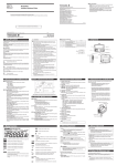
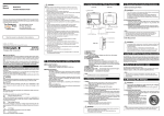
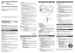
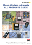
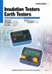
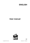
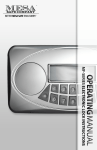
User’s
Manual
Model MY40
Insulation Resistance Tester
Thank you for purchasing the Yokogawa M&C MY40 Insulation Tester.
To optimize all the functions of the instrument, please read this manual thoroughly before operating it.
Store this manual in a safe place for future reference.
1st Edition : Nov. 2000(YG)
All Rights Reserved, Copyright ©2000, Yokogawa M&C Corporation
IM MY40-E
2nd Edition: July, 2001
1. Safety Precautions
WARNING
Always observe the following instructions. Failure to do so may result
in electrical shock or other dangers that may lead to serious injury or
the loss of life.
Yokogawa M&C Corporation is in no way liable for any damage resulting from the user's mishandling of the tester.
For safe use of this tester, the following safety symbols are used in the
user's manual:
WARNING
This indicates that the operator must refer to an explanation in the
user's manual in order to avoid the risk of serious injury or the loss of
life.
CAUTION
This indicates that the operator must refer to an explanation in the
user's manual in order to avoid the risk of injury or damage to the
tester.
Note
This provides important information for handling the tester and clarifies tester functions.
The following symbols are used on the MY40 tester.
Danger! Handle with Care.
This symbol indicates that the operator must refer to an explanation in
the user's manual in order to avoid risk of injury or death of personnel
or damage to the tester.
High-voltage Terminal
This symbol indicates a dangerous voltage level (terminals with voltages exceeding 1000 volts must be so marked). Never touch the terminals.
AC Voltage
This symbol indicates the presence of an AC voltage.
Double Insulation
2. Components
■ Always observe the following instructions. Failure to do so may
result in electric shock or other dangers that may lead to serious
injury or the loss of life.
1. During Measurement of Insulation Resistance
• A high voltage is present at the probes. Do not touch the measured
object or the earth or line terminal.
2. Immediately After Measurement of Insulation Resistance
• The probes or the measured object may remain highly charged.
Do not touch them immediately after the completion of measurement.
3. During Measurement of AC Voltages
• Do not press the MEAS key while measuring AC voltages.
• Voltage that exceeds the specified limit must not be applied to terminals.
4. Probes
• Use the probes supplied by Yokogawa M&C with this tester.
• Do not use probes that have deteriorated or are defective.
• Remove the probes from the measured object before attaching/
detaching the probes to/from the tester.
5. Insulation of Casing
• A puncture in the protective insulation may occur if there are any
cracks or other damage in the casing as a result of the instrument
having been dropped or knocked against another object.
Do not use the instrument before taking the necessary remedial
measures; ask the manufacturer to repair it.
6. The Measured Object
• Turn off the power to the measured object before you begin
measuring insulation resistance.
• Avoid touching any electrified parts while using the tester in
a location with live electricity. For safety, it is recommended that
you use a pair of rubber gloves or other alternative means.
7. Operating Environment
• Do not operate the tester in an atmosphere where any flammable
or explosive gas is present.
• Do not use the tester if there is condensation on it.
8. Disassembly
• No person, except personnel from Yokogawa M&C, is authorized
to disassemble this instrument.
Front view
1. Display window
(LCD)
3. LIGHT key
INSULATION
TESTER
LIGHT
2. MEAS key
ALARM
1000V
Enter
6. ALARM LED
7. Function selector switch
2000MΩ
500V
MEM
250V
MEAS
200MΩ
PULL LOCK
125V
V
600V MAX
COMP
OFF
Select
Clr
1000V RELEASE
8. 1000-V RELEASE button
for setting 1000-V rating
4. Protective cover fitting
5. COMPARATOR key
Rear view
Side view
12. Earth terminal
11. Shoulder strap
guide
13. Line terminal
OPEN
9. Battery cover setscrew 10. Battery cover
This symbol indicates double insulation.
3. Measuring Functions and Additional Features
■ Measuring Functions
• Measuring the insulation resistance (four ratings)
125 V/ 200 MΩ
250 V/ 200 MΩ
500 V/ 2000 MΩ
1000 V/ 2000 MΩ
• Measuring AC voltages (sine wave at 45 to 400 Hz)
• Measuring conductor resistances (0 to 400.0 Ω)
Continuity test (beeps for 40 Ω or less)
■ Additional Features
• Memory feature (data saving)
Up to 20 measured values of the insulation resistance for each
rating can be saved to memory.
• Live-line alarm
When an AC voltage of 40 V or more is applied between the
input terminals, the ALARM LED flashes and the buzzer beeps
(except during AC voltage measurement).
• Comparator
When a measured insulation resistance is less than the reference value setting, the LOW mark appears and the buzzer
beeps.
• HOLD feature
Measured insulation resistances are automatically held for
approximately five seconds.
• High-voltage indication
If a DC voltage exists between the terminals, the HV mark
and the ALARM LED come on.
• Discharge feature
The tester is designed to begin discharging when the MEAS
key is turned off.
It indicates the discharging status with a bar graph, and the
HV mark and ALARM LED come on during discharging (and
off when discharging is complete).
• Auto-power off
The tester is automatically turned off when no key operations
are performed for 10 minutes.
• LCD backlight
The backlight can be turned on/off with the LIGHT key.
• Locking the MEAS key
Pulling the MEAS key up allows for continuous measurement
over a prolonged time.
• Lock for inadvertent setting of 1000-V range
This mechanism protects the measured circuit from damage
due to inadvertent measurement with the highest voltage
(1000 V).
4. Overrange Display Functions
■ OL Display
The tester displays the OL mark when the measured resistance exceeds the following values.
Insulation resistance measurement:
For 1000 V and 500 V ratings: 2000 MΩ
For 250 V and 125 V ratings: 200 MΩ
Conductor resistance measurement: 400 Ω
■ ∞Display
The tester displays the ∞ mark when the internal calculation
exceeds the following values.
Insulation resistance measurement:
For 1000 V and 500 V ratings: approx. 4000 MΩ
For 250 V and 125 V ratings: approx. 400 MΩ
■ Change to Upper/Lower Ranges
• To upper range
When the digital reading exceeds 4000, the measuring range
changes to the next upper range.
• To lower range
When the digital reading falls below 360, the measuring range
changes to the next lower range.
■ Lower Resolution Display
If the digits below the decimal point are not stable, they can be
automatically omitted to limit the resolution.
6. Functions for Each Component
1. Display window (LCD)
Displays the measured values and the function marks (see section
5, “Display Functions”).
2. MEAS key
Used for measuring the insulation resistance only.
3. LIGHT key: Used for turning on/off the backlight.
(MEM key): Also used for setting memory.
(Enter key): Also used for confirmation for the comparator and
memory functions.
4. Protective cover fitting
5. COMP key: Used for setting the comparator.
(Select key): Also used for selection for the comparator and
memory functions.
6. ALARM LED
Flashes for the live-line alarm, and is lit as a warning for the high
-voltage alarm.
7. Function switch
A rotary switch for setting measurement ratings with the following
positions:
• 1000 V/ 2000 MΩ: Insulation resistance measurement
• 500 V/ 2000 MΩ: Insulation resistance measurement
• 250 V/ 200 MΩ: Insulation resistance measurement
• 125 V/ 200 MΩ: Insulation resistance measurement
• AC voltage measurement (maximum input voltage: 600 V)
• Power off
• Conductor resistance measurement
Continuity test
CLr: Memory clear
8. 1000-V RELEASE button
Turn the function switch to the 1000 V rating position while pressing this button.
9. Battery cover setscrew
Undo to replace batteries.
10. Battery cover
11. Shoulder strap guide
The shoulder strap is passed through it.
12. Earth terminal
Connection for earth probe.
13. Line terminal
Connection for line probe.
7. Using Protection Cover and Shoulder Strap
The tester comes with a protection cover and shoulder strap as
standard accessories.
• The protection cover can be used as a front cover
(for the display window) or as a bottom cover.
(It is set as the front cover when
delivered from the factory.)
• Using the shoulder strap allows you to position the
tester in front of your chest for ease of reading. Pass
the strap through the shoulder strap guide and adjust the length of the strap to allow you a good view
of the tester.
• Remove the cover from the front, and attach it to
the bottom using the fixing hole (B) on the surface
of the cover. This is useful when the diaplay is too
close to your body to see clearly (See the figure
on the right).
• A belt on the cover which is fitted with pieces of
Velcro, can be used to store the probes (Remove
the probes from the tester terminals when storing
them).
Protection cover fixing holes
Shoulder strap
A
B
Protection cover
Shoulder strap guide
Note
• GUARD function is not a standard function.
8. Before Measurement
5. Display Functions
: Change toward smaller values
: Change toward larger values
: Stable
Lit when the measured insulation resistance is being held.
Flashes when the battery voltage is low.
Lit when the comparator is activated.
Lit when the rating setting is 1000 V/2000 MΩ.
Lit when the measured insulation resistance is lower than
the comparator setting value.
Lit when the rating setting is 500 V/2000 MΩ.
Lit when the rating setting is 250 V/200 MΩ.
OL
Lit when:
• Pressing the MEAS key in insulation resistance measurement; and
• Residual electrical charges are present during discharging.
Lit when the memory feature is in use.
Lit when the rating setting is 125 V/200 MΩ.
Indicates the unit for AC voltage measurement.
Indicates overrange.
Indicates the unit for insulation resistances.
Indicates the extension bar graph.
Indicates the unit for conductor resistance measurement.
The extension bar graph shows how the measured value is
changing (trend) as follows:
Indicates the continuity mark, which is lit when the
measured insulation resistance is lower than 40 Ω.
Note that the number of
change.
marks means the degree of
Sub-display
Indicates:
• Comparator setting value or the storage number; or
• The storage number for memory.
Indicates the unit for insulation resistance for comparator.
1. Safety
• Read the handling precautions in this manual carefully.
• Make sure it is safe before starting measurement.
2. Battery Voltage Verification
• Make sure that the battery voltages are within the valid ratmark is not flashing).
ings (i.e. the
• If the batteries are low, replace them as specified in the battery replacement section of this manual.
Note
As the
mark indication depends on the load (current
consumption), check that the
mark does not appear for the
largest load when short-circuiting the earth probe and the line probe
(0 MΩ).
3. Connecting the Probes
• Plug the earth probe into the earth terminal.
• Plug the line probe into the line terminal.
WARNING
• Remove the probes from the measured object before attaching/
detaching the probes to/from the tester.
• Make sure the MEAS key is off when attaching/detaching
the probes to/from the tester.
4. Function Switch Verification
Be sure to confirm that the function switch is set to the desired rating.
5. 1000-V Rating
When measuring with the 1000-V rating, see section 12, “Doubleaction 1000-V Function”.
9. Battery Replacement
WARNING
• Remove the probes from the tester and then turn off
the MEAS key before opening the casing to replace the batteries.
• Do not touch the MEAS key during replacement. Otherwise,
a high voltage may be produced.
1. Loosen the battery cover setscrew, and then slide the cover off of
the main unit.
2. Replace all of the 4 batteries at the same time and make sure the
polarities of the new batteries are exactly as shown on the
battery holder.
3. After replacing the batteries, attach the battery cover and tighten the
setscrew.
CAUTION
• Do not mix batteries of different types or new batteries with used ones.
• Always remove the batteries if the tester will not be used for
a prolonged period of time. If you store the tester with the batteries
left installed, fluid is likely to leak from them, resulting in
a malfunctioning of the instrument.
10. Battery Life (Reference only)
For MY40 at rated 500 V/2000 MΩ:
Approximately 15 hours when in continuous operation with center value
indicated (approx. 50 MΩ; with standard supplied batteries).
Note
The data above is typical. Nevertheless, the battery life varies
depending on the operating conditions. Check the batteries before
measurement.
5. After Measurement
11. Measuring the Insulation Resistance
19. LIGHT and COMP Keys
WARNING
1. Before Connecting the Probes
WARNING
• Turn off the power to the measured object before connecting or
measuring insulation resistance.
• Electrical charges may be present in the cables attached to or
metal of the electrical equipment being tested. Verify that the
equipment is free from electrical charges before connecting the
testing terminals.
• Be sure to confirm that the function switch is set to the desired
rating.
The
key is used as the Select key for settings and storage numbers of the comparator and memory functions.
COMP
• Immediately after measurement, electrical charges resulting from
the applied testing voltage may remain present in the probes or
measured object.
• The tester, therefore, is designed to automatically begin
discharging electricity upon completion of measurement. Verify
that the ALARM LED turns off when discharging is complete.
The
key is used as the Enter key for settings and storage numbers of the comparator and memory functions. Pressing the Enter key
while the display is flashing, confirms selection of the setting or the
storage numbers.
LIGHT
• When setting the memory or comparator function
Turn the function switch to an insulation resistance rating position
key or the
key until all the
while pressing and holding the
displayed digits stop flashing and remain on, and the buzzer sounds.
Or position the function switch to a rating of the insulation resistance
key or the
key when all the digits appear, and
first, press the
hold the key until the buzzer sounds.
LIGHT
12. Double-action 1000-V Function
Insulation resistance ratings:
125 V/ 200 MΩ
250 V/ 200 MΩ
500 V/ 2000 MΩ
1000 V/ 2000 MΩ
2. Setting the Function Switch
Turn the function switch to the desired measurement rating position. The initial display is “---- MΩ”.
3. Connecting the Earth Probe
• If the measured object is grounded, connect the earth probe
clip to the measured object’s ground line.
• If the measured object is not grounded, this process may be
omitted.
4. Connecting the Line Probe
• Bring the line probe into contact with the measured object,
and then press the MEAS key. The display indicates the insulation resistance of the measured object.
The tester is equipped with the RELEASE button to protect the measured circuit from damage due to inadvertent measurement at 1000 V.
To select the 1000 V rating, turn the function switch to the position while
pressing this button. To cancel the 1000 V rating, turn the function switch
to the off position or another rating position.
COMP
COMP
LIGHT
Note
If the data being held is invalid, “----” is displayed and it cannot be
saved. In this case, perform measurement again and save the
data.
■ Deleting data
Data saved can be collectively deleted.
(1) Turn the function switch from power-off to the continuity test pokey (MEM).
sition (Clr) while pressing and holding the
(2) “MEM” and “CLr” appear.
key (MEM). “CLr” starts flashing.
(3) Press the
key (MEM) again while “CLr” is flashing. The buzzer
(4) Press the
sounds and all data are deleted (do not change the position of
the function dial for two seconds when “CLr” is displayed). The
tester changes its mode to measurement of conductor resistances.
LIGHT
LIGHT
20. Memory Feature (Data Saving)
Always turn off the power to the measured object before connecting or
measuring insulation resistance. If an AC voltage of more than 40 V is
applied, the ALARM LED flashes and the buzzer beeps. In this case,
stop the measurement immediately and check the power supply voltage.
14. Locing the MEAS Key (for Continuous Measurement)
The MEAS key, when pulled up to the right, can be locked to ensure the
key remains turned on. Use this mechanism when making continuous
measurement over a prolonged period. Note, however, that leaving the
key turned on for an unreasonably long time will accelerate the discharge of the batteries.
During measurement, exercise care to prevent the leadwire of
the line probe from coming into contact with the ground, floor or
any other object. Not observing this precaution may result in
a failure to measure the correct insulation resistance.
LIGHT
LIGHT
■ Backlight
• The backlight remains off while the comparator is set.
• The backlight is lit when memory is in use.
13. Live-line Alarm
Note
■ Saving data
First select a storage number as in steps (1) and (2) above. Overwriting data is possible.
(3) Perform measurement with the MEAS key.
(4) Turn off the MEAS key. The measured value is held and starts
key (Enter) while the measured value is
flashing. Press the
flashing to save it to memory (it is held for five seconds in which
time the next data cannot be saved).
15. HOLD Feature
Up to 20 measured values of the insulation resistance for each rating
can be saved to memory.
■ Displaying data
(1) Turn the function switch from power-off to a measurement rating
key (MEM).
while pressing and holding the
“MEM” appears and “no.01” (storage number) flashes on the subdisplay.
(2) Select a storage number.
key (Select) to select a storage number (no.01 to
Press the
no.20).
If an insulation resistance data is saved with the selected (displayed)
number, the insulation resistance value is displayed.
If any data is not saved with the selected (displayed) number, “----” is
displayed.
LIGHT
COMP
Note
To stop deleting of data:
Do not perform any key operation and wait for 10 seconds while
the “CLr” indication mentioned in step (3) is flashing; or
Turn the function switch to another rating.
■ Turning off the memory feature
Turn the function switch to the off position.
Measured insulation resistances are automatically held for approximately
five seconds. Turning off the MEAS key initiates holding.
17. Measuring Conductor Resistance (Continuity)
The tester can measure the conductor resistance of 0-400 Ω. The buzzer
beeps for resistances approximately 40 Ω or lower.
WARNING
• Do not press the MEAS key while measuring AC voltages.
• Voltage that exceeds the specified limit (600 V) must not be
applied to terminals. Doing so causes all digits of the measured
voltage to flash and the buzzer to beep.
WARNING
• Turn off the power to the measured object before connecting or
measuring conductor resistance.
1. Setting the Function Switch
Turn the function switch to an AC voltage
measurement (앑V) position.
2. Connecting the Earth Probe
• If the measured object is grounded, connect the earth probe clip to the measured object’s ground line.
• If the measured object is not grounded,
this process may be omitted.
3. Connecting the Line Probe
• Bring the line probe into contact with the measured object.
The display indicates the AC voltage of measured object.
21. Comparator
Sub-display
(1) Turn the function switch to a measurement rating.
1. Setting the Function Switch
Turn the function switch to a conductor resistance measurement
(
) position.
key.
(2) Press the
appears and the reference value appears on the sub(3)
display.
(4) Pressing the
key (Select) changes the reference value display as follows.
0.1 MΩ / 0.2 MΩ / 0.4 MΩ / Comparator off (no display)
The reference value currently displayed is selected as the comparator setting.
COMP
■ Setting the preset values
Each of the default preset values no.01 to no.03 can be changed
independently.
You do not have to press the MEAS key when you measure
conductor resistances.
(1) Turn the function switch from power-off to a desired rating while
key. “no.01” on the sub-display
pressing and holding the
key (Select) to select no.02 or no.03.
flashes. Press the
18. Auto Power-off
COMP
COMP
The tester is automatically turned off when no key operations are performed for 10 minutes.
The buzzer sounds 9 and a half minutes after the last key operation (at
1-sec intervals). If any measurement or key operation is not made while
the buzzer sounds, the tester is turned off. However, it is not turned off
when measurement is in progress or an alarm occurs.
key (Enter).
(2) Confirm the setting no. with the
The reference value on the main display can be set.
LIGHT
(3) Select the position of the decimal point with the
LIGHT
125V/200 MΩ
500V/2000 MΩ
1000V/2000 MΩ
5
5
50
50
1st Effective Measuring Range (MΩ)
.0200 to 10.00
.0500 to 20.00
1.000 to 500
2.000 to 1000
2nd Effective Measuring Range
Lower Limit
(MΩ)
0 to.0199
0 to .0499
0 to .999
0 to1.999
2nd Effective Measuring Range
Upper Limit
(MΩ)
10.01 to 200
20.01 to 200
501 to 2000
1001 to 2000
Center Value Indicated
(MΩ)
Lower Measuring Limit of
Resistance
(MΩ)
Rated Current
(mA)
AC Voltage Measuring Range
(V)
COMP
24. Accessories
250V/200 MΩ
0.125
0.25
0.5
2
1 to 1.2
1 to 1.2
1 to 1.2
0.5 to 0.6
Main display
Sub-display
Insulation resistance
measurement
(with comparator)
Measured value
Reference value
Comparator setting
Reference value
no.
(6) Confirm the number with the
key (Enter).
(7) Set the number for the next digit.
(8) When settings for all the digits are complete, the reference value
starts flashing.
(9) Confirm the reference value with the
key (Enter). The buzzer
sounds and the setting ends. The tester changes its mode to
measurement of insulation resistances.
LIGHT
LIGHT
Repeat steps (1) to (9) to change other preset values.
Note
key (Select).
LIGHT
COMP
Rating
COMP
key (Enter).
(4) Confirm the decimal point with the
(5) Select the number for each digit sequentially.
key (Select) changes the number as follows.
Pressing the
0 → 1 → 2 ··· 8 → 9 → 0
key
To use the tester after the auto power-off is triggered, press the
key, or turn the function switch to the off position once before
or the
proceeding with the desired operation.
22. Specifications (JIS C1302-1994 compliance)
Position of decimal point
COMP
2. Connecting the Earth Probe
Securely connect the earth probe to the measured object.
3. Connecting the Line Probe
Bring the line probe into contact with the measured object. The display indicates the resistance of the measured object.
Note
Main display
When a measured insulation resistance is less than the reference value
setting, the LOW mark appears and the buzzer sounds. Also the measured value is automatically held for 5 seconds.
■ Selecting the reference value
Select from three preset values for each rating.
Default values:
no.01: 0.1 MΩ/ no.02: 0.2 MΩ/ no.03: 0.4 MΩ
• To cancel the preset setting
Pressing the
key (Select) in step (8) returns the setting
procedure to step (1). To stop the setting, turn the function switch
to the off position.
• To set the preset values for another rating
Turn the function dial to the desired rating (insulation resistance)
in step (8).
COMP
25. External Dimensions
Unit: mm
(apptox. inch)
■ Standard Accessories
Name
Model No.
Quantity
Main unit
52.5(2.07)
125(4.92)
Protection cover
Shoulder strap
Line probe
Earth probe
Batteries
,
User s manual
93013
99005
98001
98002
—
IM MY40-E
1
1
1
1
4
1
INSULATION
TESTER
LIGHT
Enter
ALARM
1000V
2000MΩ
500V
MEM
■ Optional Accessories
103(4.06)
16. Measuring AC Voltages
250V
MEAS
200MΩ
PULL LOCK
125V
V
600V MAX
COMP
0 to 600
Tolerances under the above conditions
Insulation resistance measurement:
±(2% of rdg + 6 dgt) within the 1st effective measuring range
± (5% of rdg + 6 dgt) within the 2nd effective measuring range (Lower limit)
±(5% of rdg) within the 2nd effective measuring range (Upper limit)
Zero value indicated: 6 dgt max.
AC voltage: ±(2% of rdg + 6 dgt)
Conductor resistance measurement: ±(2% of rdg + 8 dgt)
No-load voltage: within 130% of the rated voltage
Short-circuit current: 2 mA or less
Item
Name
Standard test conditions
Ambient temperature and humidity: 23 ±5°C at 45 to 75% RH
Position: Horizontal (within 5 degrees)
Influence of external magnetic field: Earth magnetism
Battery voltage: Within effective range of the battery (the
mark must not be
indicated.)
Limit
Model No.
1. Spare probe tip for the
line probe (Model 98001)
99011
105 mm, breaker pin
2. Hard case
93015
Houses both the main unit, the line
probe and the earth probe.
B9108XA
3. Accessory bag
Soft case, approx. 100 (W) ⫻ 190 (H)
⫻ 40 (D) mm
Response time
Digital indication: 3 sec or less
Bar graph indication (static) value: approx. 2 sec
Effect of temperature
± 2% or less
98005
5. Spare probe tips for the
line probe (Model 98005)
6.
B9600GN
58 mm, general-purpose
B9600NW
360 mm, hook-shaped
7.
B9600NX
360 mm, for extension purposes
8.
B9600NZ
108 mm, sharp-pointed
9.
B9635JK
338 mm, pickax-shaped
1. 990 11
Within tolerance
When the tester is left for 1 hour with the humidity at 90% RH
3% or less of indication
The change of indication when an external field of 400 A/m DC is
applied in the most affected direction
Effect of AC component
of voltage at measuring
terminals
10% or less of indication
A change when a capacitor with 5 µF ±10% is connected in parallel to
a resistor corresponding to central indication connected
Insulation resistance
50 MΩ or more (between electric circuits and outer case)
When a voltage of 1000 V is applied.
Withstand voltage
There must not be an abnormality
(between electric circuits and outer case).
When a sine wave, or the like, is applied between the electric circuits
and the outer case at 5550 V AC and 50/60 Hz for 1 minute
5. GN
6. NW
There are no mechanical and electrical damage.
The specifications for tolerances must be met.
When a vibration frequency of 16.7 Hz and peak-to-peak amplitude of
4 mm is applied in the direction of the axis of the moving part for 1 hour
Resistance to shock
There are no mechanical and electrical damage.
The specifications for tolerances must be met.
When shock of 1000 m/s2 is applied twice in the direction of axis of
the moving part and in a direction perpendicular to the axis
Endurance
The specifications for tolerances must be met.
When a resistor corresponding to the central indication is connected
across the measuring terminals and the power switch is repeatedly
turned on and off 10 000 cycles at a rate of about 300 cycles/hour
Protection against
mistaken input
There must not be an abnormality.
When an AC voltage of 50/60 Hz at 1.2 times the rated measuring
voltage is applied to the measuring terminals for 10 seconds
23. General Specifications
Operation temperature
and humidity
Storage temperature
and humidity
Battery
External dimensions
Weight
–10°C to 60°C at 70% RH or less (no condensation)
EMC standards
Four AA-size (R6)
Approx. 125 (W) × 103 (H) × 52.5 (D) mm
Approx. 420 g (main unit and batteries only)
Approx. 600 g
(main unit, batteries, protective cover, earth probe and line probe)
Effect of radiation
immunity
EN61010-1:1993 and EN61010-2-31:1995
Insulation class2,Pollution degree 2
Overvoltage category3 (maximum input voltage: 600 V)
EN55011; 1998 Group1 ClassB
EN61326-1; 1997+A1; 1998
At the strength of radio-frequency electromagnetic field of
3V/m
• Insulation resistance measurement
1st effective measuring range : ± (5% of rdg +12dgt)
2nd effective measuring range : ± (10% of rdg +12dgt)
• AC Voltage measurement
: ± (5% of rdg +12dgt)
• Conductor resistance measurement : ± (10% of range)
1000V RELEASE
Earth probe
98002
1200(47.24)
Line probe
98001
1200(47.24)
27. Corrective Measures in Case of Failure
2.
If the instrument does not operate properly after taking the corrective
measures shown below or any other failure that is not covered here
occurs, contact the vendor from which you purchased the instrument.
3.
Failures
• The tester displays nothing after turning the function switch to the
on position.
• The display is light in color.
• The measured values are erroneous.
7. NX
9. JK
8. NZ
26. Maintenance
Safety standards
0°C to 40°C at 90% RH or less (no condensation)
Clr
4. 980 05
Effect of humidity
Effect of external
magnetic field
Resistance to vibration
OFF
Cable length: 1000 mm
4. Replaceable-type line probe
Test condition
From the instant the resistors whose values correspond to central
indication and zero indications are abruptly connected, to when
the pointer reaches a level within tolerance
1st effective measuring range: maximum, center, and minimum
indicated values
Deviation from those values when ambient temperature is varied from
20°C by ± 20°C.
Select
Description
■ Storage Conditions
• Temperature and humidity:-10°C to 60°C at 70% RH or less
• Remove the batteries before storing the tester.
• Avoid storing the tester in a location where there is:
moisture; exposure to direct sunlight;
a high-temperature heat source nearby;
exposure to severe mechanical vibrations;
a large amount of dust and/or salt, or a corrosive gas.
■ Removal of Dirt
Do not use volatile solvents (such as paint thinners or benzine) as
they are likely to cause discoloration. Wipe off dirt with a cloth
dampened water or alcohol.
■ Calibration Cycle
It is recommended that the tester be calibrated once every year for
correct operation; ask Yokogawa M&C to do the periodic calibration
for you.
Test Equipment Depot - 800.517.8431 - 99 Washington Street Melrose, MA 02176
FAX 781.665.0780 - TestEquipmentDepot.com
Items to Check
• The batteries are installed properly and their power levels are not
low.
• The measuring probes are connected correctly and are not damaged.
• Whether the failure reoccurs after turning off the power and retrying the operation.
Error Messages
Err.0: An internal operation failure.
Turn off the power and retry the operation.
* If the failure reoccurs, the tester needs repairing.
Err.1: Cannot save the comparator or memory settings.
Measurement functions other than the comparator and memory
functions operate normally.
Settings and data saved without the error indication (Err.1) can
be used.
* If the failure reoccurs, the tester needs repairing.
Err.2: An internal operation failure.
Turn off the power and retry the operation.
* If the failure reoccurs, the tester needs repairing.
■ About This Manual
The contents of this manual are subject to change without prior notice.
Under absolutely no circumstances may the contents of this manual
be transcribed or copied, in part or in whole, without obtaining permission.
Every effort has been made to ensure accuracy in the preparation of
this manual. Should any errors or omissions come to your attention
however, please inform Yokogawa M&C Corporation accordingly.