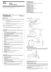
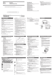
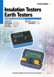
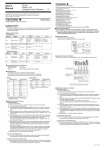
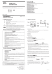
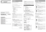
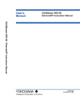
1
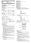
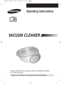
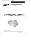
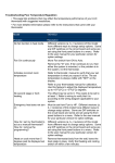
User’s
Manual
3. Components and Their Functions
WARNING
Model MY10
Insulation Resistance Tester
Thank you for purchasing the Yokogawa Meters & Instruments MY10
Insulation Tester.
To optimize all the functions of the instrument, please read this manual
thoroughly before operating it.
Store this manual in a safe place for future reference.
1st Edition : Jan. 2000(YG)
All Rights Reserved, Copyright©1999, Yokogawa M&C Corporation
IM MY10-E
6th Edition: Dec. 2006 (KP)
■ About This Manual
The contents of this manual are subject to change without prior notice.
Under absolutely no circumstances may the contents of this manual
be transcribed or copied, in part or in whole, without obtaining permission.
Every effort has been made to ensure accuracy in the preparation of
this manual. Should any errors or omissions come to your attention
however, please inform Yokogawa M&C Corporation accordingly.
1. Safety Precautions
Always observe the following instructions. Failure to do so may result
in electric shock or other dangers that may lead to serious injury or the
loss of life.
Yokogawa Meters & Instruments Corporation is in no way liable for any
damage resulting from the user's mishandling of the tester.
For safe use of this tester, the following safety symbols are used in the
user's manual:
WARNING
Indicates a hazard that may result in the loss of life or serious injury of
the user unless the described instruction is abided by.
CAUTION
Indicates a hazard that may result in an injury to the user and/or physical damage to the product or other equipment unless the described
instruction is abided by.
Note
This provides important information for handling the tester and clarifies tester functions.
The following symbols are used on the MY10 tester.
Danger! Handle with Care.
This symbol indicates that the operator must refer to an explanation in
the user’s manual in order to avoid risk of injury or death of personnel
or damage to the tester.
High-voltage Terminal
This symbol indicates a dangerous voltage level (terminals with voltages exceeding 1000 volts must be so marked). Never touch the terminals.
AC Voltage
This symbol indicates the presence of an AC voltage.
Double Insulation
This symbol indicates double insulation.
■ Always observe the following instructions. Failure to do so may
result in electric shock or other dangers that may lead to serious
injury or the loss of life.
1. During Measurement of Insulation Resistance
• A high voltage is present at the probes. Do not touch the measured
object or the earth or line terminal.
2. Immediately After Measurement of Insulation Resistance
• The probes or the measured object may remain highly charged.
Do not touch them immediately after the completion of measurement.
3. During Measurement of AC Voltages
• Do not press the MEAS key while measuring AC voltages.
• Voltage that exceeds the specified limit must not be applied to terminals.
4. Probes
• Use the probes supplied by Yokogawa Meters & Instruments with
this tester.
• Do not use probes that have deteriorated or are defective.
• Remove the probes from the measured object before attaching/
detaching the probes to/from the tester.
5. Insulation of Casing
• A puncture in the protective insulation may occur if there are any
cracks or other damage in the casing as a result of the instrument
having been dropped or knocked against another object.
Do not use the instrument before taking the necessary remedial
measures; ask the manufacturer to repair it.
6. The Measured Object
• Turn off the power to the measured object before you begin
measuring insulation resistance.
• Avoid touching any electrified parts while using the tester in
a location with live electricity. For safety, it is recommended that
you use a pair of rubber gloves or other alternative means.
7. Operating Environment
• Do not operate the tester in an atmosphere where any flammable
or explosive gas is present.
• Do not use the tester if there is condensation on it.
8. Disassembly
• No person, except personnel from Yokogawa Meters & Instruments,
is authorized to disassemble this tester.
■ Measurement Categories
Measurement category
Description
For measurements performed on circuits
not directly connected to MAINS.
Remarks
1
CAT.1
2
CAT.2
For measurements performed on circuits
Appliances, portable equipments, etc.
directly connected to the low voltage installation.
3
CAT.3
For measurements performed
in the building installation.
Distribution board, circuit breaker, etc.
4
CAT.4
For measurements performed
at the source of the low-voltage installation.
Overhead wire, cable systems, etc.
Internal Wiring
Entrance
Cable
CAT.4
Distribution
Board
• Turn off the power to the measured object before connecting the
probes or measuring insulation resistance.
• Electrical charges may be present in the cables attached to
or metal of the electrical equipment being tested. Verify that
the equipment is free from electrical charges before connecting
the testing terminals.
2. MEAS key
9. Shoulder strap guide
6. ALARM LED
8. Battery cover
4. Protective cover fitting
Outlet
Equipment
2. Measuring Functions and Additional Features
■ Measuring Functions
• Measuring the insulation resistance
• Measuring AC voltages (sine wave at 50/60 Hz)
■ Additional Features
• Discharge feature
The tester is designed to begin discharging when the MEAS
key is turned off. The ALARM LED turns off when discharging
is complete.
• Battery check
This function verifies if the battery voltages are within the valid
ranges. (When the battely is checked, the pointer must be
within the BATT mark.)
• Phosphorescent scale plate
The indicator window lights up according to the intensity of
light.
• Locking the MEAS key
Pulling the MEAS key up allows for continuous measurement
over a prolonged period of time.
2. Connecting the Earth Probe
• Securely connect the earth probe to the measured object’s
ground line (if the measured object is not grounded, this
process may be omitted).
3. Connecting the Line Probe
• Bring the line probe into contact with the measured object,
and then press the MEAS key. The pointer indicates the insulation resistance of the measured object.
Note
7. Battery cover setscrew
3. BATT CHECK key
5. Zero adjustment (screw)
10. Earth terminal
11. Line terminal
Side view
1. Indicator window
2. MEAS key
3. BATT CHECK key
Verifies if the battery voltages are within the valid ranges.
4. Protective cover fitting
5. Zero adjustment (screw)
6. ALARM LED
• Discharge feature (On➞ Off)
When lit, it indicates that a capacitive component in the
measured object remains electrified and will light up even if
measurement has been completed. It turns off when discharge
is complete.
7. Battery cover setscrew Undo to replace batteries.
8. Battery cover
9. Shoulder strap guide
The shoulder strap is passed through it.
10. Earth terminal
Connection for earth probe.
11. Line terminal
Connection for line probe.
During measurement, exercise care to prevent the leadwire of
the line probe from coming into contact with the ground, floor or
any other object. Not observing this precaution may result in
a failure to measure the correct insulation resistance.
4. After Measurement
WARNING
• Immediately after measurement, electrical charges resulting from
the applied testing voltage may remain present in the probes or
measured object.
• The tester, therefore, is designed to automatically begin
discharging electricity upon completion of measurement. Verify
that the ALARM LED turns off when discharging is complete.
Locking the MEAS Key (for Continuous Measurement)
The MEAS key, when pulled up to the right, can be locked to ensure
the key remains turned on. Use this mechanism when making continuous measurement over a prolonged period. Note, however, that leaving the key turned on for an unreasonably long time will accelerate the
discharge of the batteries.
Battery Life (reference only)
For MY10-03 at rated 500 V/100 MΩ:
Approximately 10 hours when in continuously operation with central
indication (approx. 2 MΩ; with standard supplied batteries).
Note
Note
T
1. Before Connecting the Probes
WARNING
1. Indicator window
CAT.3 CAT.2
CAT.1
Fixed Equipment,
etc.
Rear view
Front view
5. Measuring the Insulation Resistance
• GUARD function is not a standard function.
4. Before Measurement
1. Safety
• Read the handling precautions in this manual carefully.
• Make sure it is safe before starting measurement.
2. How to Read the Scale
• Read the value from the top-right of the scale.
3. Zero Adjustment
• Confirm that the pointer is at the center of the infinity sign (∞);
if it is, do not press the MEAS key.
• If it is not, adjust the pointer to indicate the center of the infinity
sign (∞) with the zero adjustment screw using a slotted screwdriver.
4. Battery Voltage Verification
• Press the BATT CHECK key to make sure the battery voltages
are within the valid ranges. (When the battely is checked, the
pointer must be within the BATT mark.)
• If the batteries are low, replace them as specified in the battery
replacement section of this manual.
5. Connecting the Probes
• Plug the earth probe into the earth terminal.
• Plug the line probe into the line terminal.
WARNING
• Remove the probes from the measured object before attaching/
detaching the probes to/from the tester.
• Make sure the MEAS key is off when attaching/detaching
the probes to/from the tester.
The data above is typical. Nevertheless, the battery life varies
depending on the operating conditions. Check the batteries before
measurement.
6. Measuring AC Voltages
WARNING
• Do not press the MEAS key while measuring AC voltages.
Otherwise, it may result in a failure.
• Voltage that exceeds the specified limit must not be applied to
terminals.
1. Connecting the Earth Probe
• Securely connect the earth probe to the measured object’s
ground line (if the measured object is not grounded, this process may be omitted).
2. Connecting the Line Probe
• Bring the line probe into contact with
the measured object.
The pointer indicates the AC voltage.
Read the value on the voltage measurement scale (~ V).
If the voltage of 20 V AC or more is
present between the earth and line
terminals, the ALARM LED turns on.
Note
When measuring insulation resistance, the tester can also be used
to verify that there is no voltage present at the measured object.
7. Specifications
8. General Specifications
11. Accessories
■ Standard Accessories
MY10-01
Model
MY10-02
MY10-03
MY10-04
MY10-05
125 V/20 M Ω
250 V/50 M Ω
500 V/100 M Ω
500 V/1000 M Ω
1000 V/2000 M Ω
Central Indication
0.5 M Ω
1MΩ
2MΩ
20 M Ω
50 M Ω
1st Effective
Measuring Range
0.02 to 10 M Ω
0.05 to 20 M Ω
0.1 to 50 M Ω
1 to 500 M Ω
2 to 1000 M Ω
2nd Effective
Measuring Range
0.01 to 0.02 M Ω
10 to 20 M Ω
0.01 to 0.05 M Ω
20 to 50 M Ω
0.05 to 0.1 M Ω
50 to 100 M Ω
0.5 to 1 M Ω
500 to 1000 M Ω
1 to 2 M Ω
1000 to 2000 M Ω
Rating
Lower Measuring Limit of
Resistance
0.125 M Ω
0.25 M Ω
0.5 M Ω
1MΩ
2MΩ
Rated Current
1 to 1.2 mA
1 to 1.2 mA
1 to 1.2 mA
0.5 to 0.6 mA
0.5 to 0.6 mA
0 to 250 V
0 to 300 V
0 to 500 V
0 to 500 V
0 to 500 V
AC Voltage
Measuring Range
Operation temperature
and humidity
Storage temperature
and humidity
Battery
External dimensions
Weight
Safety standards
EMC Standard
Effect of radiation
ilmmunity
■ First and second effective measuring ranges
0
∞
<1>
<2
>
<2
>
Tolerances under the above conditions
Resistance measurement: ±5% of reading within the 1st effective measuring range
±10% of reading within the 2nd effective measuring range
Infinity and zero indications: 0.7% or less of scale length
AC voltage: ±10% of the maximum value
No-load voltage: Within 130% of the rated voltage
Short-circuit current: 12 mA or less
Scale length: Approx. 78 mm
Item
Standard test conditions
Ambient temperature and humidity: 23 ±5°C at 45 to 75% RH
Position: Horizontal (within 5 degrees)
Influence of external magnetic field: Earth magnetism
Battery Voltage : Within effective range for the battery (When the battery is checked,
the pointer must be within the BATT mark.)
Limit
Test condition
From the instant the resistors whose values correspond to central
indication and zero indications are abruptly connected, to when
the pointer reaches a level within tolerance
Response time
3 sec or less
Friction
No friction is recognized
Effects of inclination
2% or less of the scale length
Effect of temperature
(1) 5% or less
(2) 0.7% or less of scale length
(1) Deviation from central indication when ambient temperature is
varied from 20°C by ±20°C
(2) Deviation from infinity and zero indications when ambient
temperature is varied from 20°C by ±20°C
Effect of humidity
Within tolerance
When the tester is left for 1 hour with the humidity at 90% RH
Effect of external
magnetic field
3% or less of indication
The change of indication when an external field of 400 A/m DC is
applied in the most affected direction
Effect of
AC component of
measuring terminal voltage
10% or less of indication
A change when a capacitor with 5µF ±10% is connected in parallel to
a resistor corresponding to central indication connected
Insulation resistance
50MΩ or more (between electric circuits and outer case)
When tested at 500 V if the rated measuring voltage is 500 V or less or
at a voltage identical to the rated voltage if the rated voltage exceeds
500 V
Deviation from the infinity indication when the tester is tilted from
a horizontal position by 30 degrees
Dielectric
withstand voltage
There must not be an abnormality.
(between electric circuits and outer case)
When a sine wave, or the like, is applied between the electric circuits
and the outer case at 5550 V AC and 50/60 Hz for 1 minute
Resistance to vibration
The specifications for tolerances, friction, and the effect of tilting
must be met. There are no mechanical and electrical damage.
When a vibration frequency of 16.7 Hz and peak-to-peak amplitude of
4 mm is applied in the direction of the axis of the moving part for 1 hour
Resistance to shock
The specifications for tolerances, friction, and the effect of tilting
must be met. There are no mechanical and electrical damage.
When shock of 1000 m/s2 is applied twice in the direction of axis of
the moving part and in a direction perpendicular to the axis
Endurance
The specifications for tolerances and friction must be met.
When a resistor corresponding to the central indication is connected
across the measuring terminals and the power switch is repeatedly
turned on and off 10 000 cycles at a rate of about 300 cycles/hour
Input over-voltage
protection
There must not be an abnormality.
When an AC voltage of 50/60 Hz at 1.2 times the rated measuring
voltage is applied to the measuring terminals for 10 seconds
AA-size (4), [R6]
Approx. 125 (W) × 103 (H) × 52.5 (D) mm
Approx. 500 g (main unit and batteries only)
Approx. 600 g
(main unit, batteries, protective cover, earth probe and line probe)
EN61010-1, EN61010-2-31
Insulation class2,Pollution degree 2
Measurement category3 (maximum input voltage: 600 V)
EN55011 ClassB Group1
EN61326 ClassB
At the strength of radio-frequency electromagnetic field of 3 V/m
• Insulation resistance measurement
1st effective measuring range : ±10% of rdg
2nd effective measuring range : ±20% of rdg
Infinity and zero indications
: 1.4% or less of scale length
• AC Voltage measurement
: ±10% of FS
9. Using Protection Cover and Shoulder Strap
The tester comes with a protection cover and shoulder strap as
standard accessories.
• The protection cover can be used as a front cover
(for the indicator window) or as a bottom cover.
Protection cover fixing holes
(It is set as the front cover when
Shoulder strap
delivered from the factory.)
• Using the shoulder strap allows
A
you to position the tester in
B
front of your chest for ease of
reading. Pass the strap through
the shoulder strap guide and
adjust the length of the strap to
allow you a good view of the tester.
• Remove the cover from the front,
and attach it to the bottom using
the fixing hole (B) on the surface Protection cover
of the cover. This is useful when
Shoulder strap guide
the scale is too close to your
body to see clearly (See the figure
on the right).
• A belt on the cover which is fitted with pieces of Velcro, can be
used to store the probes (Remove the probes from the tester
terminals when storing them).
10. External Dimensions
Main unit
125 (4.92)
52.5 (2.07)
Unit: mm
(approx. inch)
Earth probe
1200 (47.24)
Line probe
1200 (47.24)
Model No.
Protection cover
Shoulder strap
Line probe
Earth probe
Batteries
User’s manual
-10 to 60°C at 70% RH or less (no condensation)
103 (4.06)
<1> 1st effective measuring range
<2> 2nd effective measuring range
The values which belong to both the first and second ranges in the table
above, are included in the first range.
Central indication
Name
0 to 40°C at 90% RH or less (no condensation)
Quantity
93013
99005
98001
98002
—
IM MY10-E
1
1
1
1
4
1
■ Optional Accessories
Name
Model No.
Description
1. Spare probe tip for the line
probe (Model 98001)
99011
105 mm, breaker pin
2. Hard case
93015
Houses both the main unit, the line probe
and the earth probe.
3. Accessory bag
4. Replaceable-type line probe
B9108XA
98005
Soft case, approx. 100 (W) ⫻ 190 (H)
⫻ 40 (D) mm
Cable length: 1000 mm
5. Spare probe tips for the line
probe (Model 98005)
B9600GN 58 mm, general-purpose
6.
B9600NW 360 mm, hook-shaped
7.
B9600NX
360 mm, for extension purposes
8.
B9600NZ
108 mm, sharp-pointed
9.
B9635JK
338 mm, pickax-shaped
12. Battery Replacement
WARNING
• Remove the probes from the tester and then turn off
the MEAS key before opening the casing to replace the batteries.
• Do not touch the MEAS key during replacement. Otherwise,
a high voltage may be produced.
1. Loosen the battery cover setscrew, and then slide the cover off of the
main unit.
2. Replace all of the 4 batteries at the same time and make sure the
polarities of the new batteries are exactly as shown on the battery holder.
3. After replacing the batteries, attach the battery cover and tighten the
setscrew.
CAUTION
• Do not mix batteries of different types or new batteries with used ones.
• Always remove the batteries if the tester will not be used for a prolonged
period of time. If you store the tester with the batteries left installed, fluid
is likely to leak from them, resulting in a malfunctioning of the instrument.
13. Maintenance
■ Storage Conditions
• Temperature and humidity:-10°C to 60°C at 70% RH or less
• Remove the batteries before storing the tester.
• Avoid storing the tester in a location where there is:
moisture; exposure to direct sunlight;
a high-temperature heat source nearby;
exposure to severe mechanical vibrations;
a large amount of dust and/or salt, or a corrosive gas.
■ Removal of Dirt
Do not use volatile solvents (such as paint thinners or benzine) as they
are likely to cause discoloration. Wipe off dirt with a cloth dampened
water or alcohol.
■ Calibration Cycle
It is recommended that the tester be calibrated once every year for correct
operation; ask Yokogawa M&C to do the periodic calibration for you.
Yokogawa Meters & Instruments Corporation
International Sales Dept.
Tachihi Bld. No.2, 6-1-3, Sakaecho, Tachikawa-shi,Tokyo 190-8586 Japan
Phone: 81-42-534-1413, Facsimile: 81-42-534-1426
YOKOGAWA CORPORATION OF AMERICA (U.S.A.)
Phone: 1-770-253-7000 Facsimile: 1-770-251-2088
YOKOGAWA EUROPE B. V. (THE NETHERLANDS)
Phone: 31-334-64-1611 Facsimile: 31-334-64-1610
YOKOGAWA ENGINEERING ASIA PTE. LTD. (SINGAPORE)
Phone: 65-6241-9933 Facsimile: 65-6241-2606
YOKOGAWA AMERICA DO SUL S. A. (BRAZIL)
Phone: 55-11-5681-2400 Facsimile: 55-11-5681-1274
YOKOGAWA MEASURING INSTRUMENTS KOREA CORPORATION (KOREA)
Phone: 82-2-551-0660 to -0664 Facsimile: 82-2-551-0665
YOKOGAWA AUSTRALIA PTY. LTD. (AUSTRALIA)
Phone: 61-2-9805-0699 Facsimile: 61-2-9888-1844
YOKOGAWA INDIA LTD. (INDIA)
Phone: 91-80-4158-6000 Facsimile: 91-80-2852-1441
YOKOGAWA SHANGHAI TRADING CO., LTD. (CHINA)
Phone: 86-21-6880-8107 Facsimile: 86-21-6880-4987
YOKOGAWA MIDDLE EAST E. C. (BAHRAIN)
Phone: 973-358100 Facsimile: 973-336100
LTD. YOKOGAWA ELECTRIC (RUSSIAN FEDERATION)
Phone: 7-095-737-7868 Facsimile: 7-095-737-7869
IM3E-2006.2