1
GXD Amplifier
User Manual
GXD 4
GXD 8
TD-000450-01-A
*TD-000450-01*
EXPLANATION OF SYMBOLS
The term “WARNING!” indicates instructions regarding personal safety. If the instructions are not followed the result may be bodily injury or death.
The term “CAUTION!” indicates instructions regarding possible damage to physical equipment. If these instructions are not followed, it may result in
damage to the equipment that may not be covered under the warranty.
The term “IMPORTANT!” indicates instructions or information that are vital to the successful completion of the procedure.
The term "NOTE" is used to indicate additional useful information.
The intent of the lightning flash with arrowhead symbol in a triangle is to alert the user to the presence of un‑insulated "dangerous"
voltage within the product's enclosure that may be of sufficient magnitude to constitute a risk of electric shock to humans.
The intent of the exclamation point within an equilateral triangle is to alert the user to the presence of important safety, and operating
and maintenance instructions in this manual.
IMPORTANT SAFETY INSTRUCTIONS
WARNING!: TO PREVENT FIRE OR ELECTRIC SHOCK, DO NOT EXPOSE THIS EQUIPMENT TO RAIN OR MOISTURE.
SP
FR
1. Read these instructions.
DE
3. Heed all warnings.
CH
4. Follow all instructions.
AR
2. Keep these instructions.
5. Do not use this apparatus near water.
6. Do not submerge the apparatus in water or liquids.
7. Do not use any aerosol spray, cleaner, disinfectant or fumigant on, near or into the apparatus.
8. Clean only with a dry cloth.
9. Do not block any ventilation opening. Install in accordance with the manufacturer's instructions.
10.Keep ventilation opening free of dust or other matter.
11.Do not install near any heat sources such as radiators, heat registers, stoves, or other apparatus (including amplifiers) that produce heat.
12.To reduce the risk of electrical shock, the power cord shall be connected to a mains socket outlet with a protective earthing connection.
13.Do not defeat the safety purpose of the polarized or grounding-type plug. A polarized plug has two blades with one wider than the other. A
grounding type plug has two blades and a third grounding prong. The wide blade or the third prong are provided for your safety. If the provided
plug does not fit into your outlet, consult an electrician for replacement of the obsolete outlet.
14.Protect the power cord from being walked on or pinched particularly at plugs, convenience receptacles, and the point where they exit from
the apparatus.
15.Do not unplug the unit by pulling on the cord, use the plug.
16.Only use attachments/accessories specified by the manufacturer.
17.Unplug this apparatus during lightning storms or when unused for long periods of time.
18.Refer all servicing to qualified service personnel. Servicing is required when the apparatus has been damaged in any way, such as power-supply
cord or plug is damaged, liquid has been spilled or objects have fallen into the apparatus, the apparatus has been exposed to rain or moisture,
does not operate normally, or has been dropped.
19.The appliance coupler, or the AC Mains plug, is the AC mains disconnect device and shall remain readily operable after installation.
20.Adhere to all applicable, local codes.
21.Consult a licensed, professional engineer when any doubt or questions arise regarding a physical equipment installation.
TD-000450-01-A
2 (DRAFT 2015/20/07)
Maintenance and Repair
WARNING!: Advanced technology, e.g., the use of modern materials and powerful electronics, requires specially adapted
maintenance and repair methods. To avoid a danger of subsequent damage to the apparatus, injuries to persons and/or the
creation of additional safety hazards, all maintenance or repair work on the apparatus should be performed only by a QSC
authorized service station or an authorized QSC International Distributor. QSC is not responsible for any injury, harm or related
damages arising from any failure of the customer, owner or user of the apparatus to facilitate those repairs.
FCC Statement
NOTE: This equipment has been tested and found to comply with the limits for a Class B digital device, pursuant to Part 15 of the
FCC Rules.
These limits are designed to provide reasonable protection against harmful interference in a residential installation. This equipment generates, uses
and can radiate radio frequency energy and, if not installed and used in accordance with the instructions, may cause harmful interference to radio
communications. However, there is no guarantee that interference will not occur in a particular installation. If this equipment does cause harmful
interference to radio or television reception, which can be determined by turning the equipment off and on, the user is encouraged to try to correct
the interference by one or more of the following measures:
• Reorient or relocate the receiving antenna.
• Increase the separation between the equipment and receiver.
SP
FR
DE
CH
• Connect the equipment into an outlet on a circuit different from that to which the receiver is connected.
• Consult the dealer or an experienced radio/TV technician for help.
Warranty
For a copy of the QSC Limited Warranty, visit the QSC Audio Products website at www.qsc.com
AR
TD-000450-01-A
3 (DRAFT 2015/20/07)
Introduction
The GXD Class-D amplifiers have been engineered for high performance output and optimized for maximum real-world headroom into 4Ω and 8Ω
loudspeaker systems. The power levels of the GXD amplifiers are matched to the most popular loudspeakers:
• GXD 4, per channel – 400 W into 8Ω, and 600 W into 4Ω (1600 W peak)
• GXD 8, per channel – 800 W into 8Ω, and 1200 W into 4Ω (4500 W peak)
The Class-D amplifier topology is very efficient, making the GXD amplifiers small and light. In addition the Universal Power Supply used in the
GXD helps to reduce weight. Both amplifiers are 2RU and are only 229 mm (9 inches) deep. The GXD 4 weighs in at 5 kg (11 lbs), the GXD 8 is at
5.9 kg (13 lbs).
The GXD amplifiers have an LCD for control and monitoring, with three buttons for menu navigation, and two knobs for adjusting parameters. There
are 20 User Presets that can be edited, stored and recalled to match any configuration or system
Each channel has parallel XLR and ¼” TRS connectors for inputs. The outputs are professional NL4 and binding post connectors for mono and bi-amp
speaker connectivity. You can keep your amplifier up-to-date with software updates using the USB connector.
Both amplifiers have complete loudspeaker processing:
• Channel Gain & Polarity
• 4th Order Linkwitz Riley Highpass and Lowpass Filters
• 4-band Parametric EQ
SP
FR
DE
CH
AR
• 50 mSec of Alignment Delay
• QSC Power Limiting
Package Contents
1. Quick‑Start Guide TD-000449-00
3. IEC AC Power Cord
2. GXD Amplifier
4. USB Cable
Rack-Mount the Amplifier
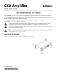
The GXD Series amplifiers are designed to be mounted in a standard rack-mount unit. The amplifiers are 2RU high, and 229 mm (9 in) deep.
1. Secure the amplifier in the rack with four screws (not included).
CAUTION!: Be sure that nothing is blocking the front or rear ventilation openings, and that each side has a minimum of
2 cm clearance.
TD-000450-01-A
4 (DRAFT 2015/20/07)
Features
Amplifier Front Panel
1
SP
FR
2
3
4
5
6
7
— Figure 1 —
8 9 10 11 12
1. Air Vents
5. Channel A CLIP (red)
9. LCD Screen
2. Power Button
6. HOME Button
10.Channel B Signal Present (green)
3. Channel A Signal Present (green)
7. ENTER Button
11.Channel B GAIN and function selection
4. Channel A GAIN
8. EXIT Button
12.Channel B CLIP (red)
Amplifier Rear Panel (Figure 2 GXD 4, Figure 3 GXD 8)
DE
CH
AR
1
2
3
1
2
3
4
5
6
4
7
8
— Figure 2 —
6
5
7
— Figure 3 —
8
9
10
11
12
9
10
11
12
1. Channel 1 and Channel 2 Input XLRs
(female)
5. Channel A Output NL4 Connector
9. Circuit Breaker (GXD 4–11 A, GXD 8–20 A)
6. Channel B Output Binding Posts
2. Channel 1 and Channel 2 Input TRS female
10.Locking IEC Power Connection
7. Channel B Output NL4 Connector
3. USB Connector
11.Rear Rack‑mount Bracket
8. Air Vents
12.Front Rack‑mount Brackets
4. Channel A Output Binding Posts
TD-000450-01-A
5 (DRAFT 2015/20/07)
Connections
Inputs (Channels 1 & 2)
See Figure 4
Input Impedance: 20k ohms Balanced, 10k ohms Unbalanced See Table 1 for wiring.
1. XLR female
2. ¼" female TRS Phone Jack
3. USB Standard B connector - Used for updating the amplifier firmware, refer to the GXD User Manual
for details.
1
2
3
— Figure 4 —
Outputs (Channels A & B)
Input Wiring
See Figure 5
4Ω or 8Ω impedance
Connector
POS
NEG
GROUND
XLR
2
3
1
1/4"
TIP
RING
SLEEVE
CAUTION!: Do not combine the audio outputs in any way. Do not connect the audio
outputs to ground.
SP
FR
DE
— Table 1 —
Wiring Be sure to observe polarity.
• NL4 connector – See Figure 6
• Binding Posts - Use banana plugs or wire directly.
CH
Power Output
AR
21+
8Ω
4Ω
Total
GXD 4
400 W
600 W
1200 W
GXD 8
800 W
1200 W
2400 W
Amplifier
2+
1-
— Table 2 —
Male NL4 Wiring
— Figure 6 —
GXD 4 Outputs
— Figure 5 —
AC Power
WARNING!: The power cord shall be connected to a mains socket outlet with a protective earthing connection.
See Figure 7
Connect the IEC power cord to the AC receptacle on the rear of the amplifier.
Push to reset Breaker when necessary.
Power Consumption
Amplifier
Voltage
Current
Frequency
GXD 4
100–240 VAC
~3.3 A–1.6 A
50/60 Hz
GXD 8
100–240 VAC
~6.3 A–3.1 A
50/60 Hz
— Table 3 —
TD-000450-01-A
6 (DRAFT 2015/20/07)
— Figure 7 —
Controls
See Figure 8
1. Channel A CLIP indicator – illuminates red when the input is high enough to cause the channel to clip.
2. Channel A SIG (signal) present indicator – illuminates green when there is a signal applied to the input.
3. Power Switch/LED on/off – Illuminates blue when on.
4. Adjust Channel A GAIN
5. User Interface
1
a. HOME – go to HOME screen / view current PRESET
A
2
b. ENTER – select highlighted item and/or confirm
parameter change
c. EXIT – return to previous screen and/or undo parameter change
6. Adjust Channel B GAIN, selects and adjusts controls
CLIP
SIG
+
A
7. Channel B SIG (signal) presence indicator – illuminates green when
there is a signal applied to the input.
GAIN
3
4
8. Channel B CLIP indicator – illuminates red when the input is high
enough to cause the channel to clip.
ENTER
EXIT
b
c
6
User Interface
— Figure 8 —
GXD Signal Flow
SP
FR
DE
Clip
1
CH
AR
A/D
Converter
Digital Signal Processing (DSP)
Signal
Presence
Sensitivity
Gain
Routing
Matrix
High-pass
Filter
LCD
Polarity
Low-pass
Filter
4-band
PEQ
Delay
Limiter
Meter
D/A
Converter
A
Meter
D/A
Converter
B
LCD
Crossover
2
A/D
Converter
Signal
Presence
Gain
High-pass
Filter
Polarity
Low-pass
Filter
4-band
PEQ
Delay
Limiter
Clip
— Figure 9 —
Setup and Operation
Menu Tree
PRESET
STEREO DSP*
DSP A / DSP B*
UTILITIES
PRESET RECALL
SENSITIVITY
SENSITIVITY
STATUS
PRESET SAVE
CROSSOVER
CROSSOVER
CONTRAST
PRESET SAVE AS
EQ
EQ
TIMEOUT
DELAY
DELAY
LOCKOUT
LIMITER
LIMITER
RESET
* STEREO DSP and DSP A / DSP B
depend on the selected configuration.
TD-000450-01-A
— Figure 10 —
7 (DRAFT 2015/20/07)
7
GAIN/DSP CONTROL
a
5
8
10.0
STATUS: OK
HOME
B
B
dB
-100
PROCESSING
AMPLIFIER
CLIP
SIG
P1: ST SAT FULL RANGE
Navigation Key
Turn
Knob B (or A)
Select / Press
Adjust
B
Home Screen
1
See Figure 11
From any screen
3
5
6
7
8
HOME
1. Asterisk (*) indicating an unsaved change to the preset
2
*P1: ST SAT FULL RANGE
A
LIMIT
CLIP
dB
-100
B
4
10.0
STATUS: OK
— Figure 11 —
2. Currently active preset location (P1) and name
3. Output channel letter A and B
4. Limiter level indicator (Channels A and B)
5. LIMIT and CLIP indicators
6. Output meter A and B (visual)
7. Output gain (digital) range = -100 to +10 dB (Channels A and B)
8. Amplifier STATUS
Main Navigation Menu
SP
FR
DE
CH
AR
P1: ST SAT FULL RANGE
See Figure 12
From HOME
ENTER
1. Previous selection – PRESETS
2. Currently selected – STEREO DSP (or DSP A and DSP B)
3. Next selection – UTILITIES
4. Instructions
1
PRESETS
2
STEREO DSP
3
4
ENTER TO SELECT
UTILITIES
— Figure 12 —
Configurations
There are four basic types of configuration selected by presets:
• Figure 13 – 2 channels in, stereo DSP, 2 channels out – Channel controls are linked, audio signals are not combined. (P1 through P7)
• Figure 14 – 2 channels in, separate DSP, 2 channels out – Channel controls are not linked except sensitivity. (P8 through P10)
• Figure 15 – 1 or 2 channels in, separate DSP, 2 channels out – Channel controls are not linked except sensitivity. (P11 through P18)
• Figure 16 – 1 or 2 channels in, stereo DSP, 2 channels out – Channel controls are linked, audio signals are combined. (P19 and P20)
1
2
ST
DSP
A
B
— Figure 13 —
1
DSP
2
DSP
A
B
— Figure 14 —
1
DSP
2
DSP
A
1
ST
DSP
2
B
— Figure 15 —
A
B
— Figure 16 —
For ST (stereo) DSP presets, the DSP functionality (Crossover, PEQ, Delay, Limiter) controls are linked. Sensitivity is always linked.
PRESET
A preset configures the inputs and outputs, along with setting the DSP. When you make changes to the DSP, you can save your setup in any of the 20
preset locations. Refer to "Preset Defaults" on page 12 for the preset factory defaults.
P1: ST SAT FULLRANGE
+
View Current Preset Configuration
From HOME
To return
1
2
HOME
HOME
ST
DSP
A
B
HOME TO RETURN
— Figure 17 —
TD-000450-01-A
8 (DRAFT 2015/20/07)
PRESET RECALL
Recall a preset to configure the amplifier to meet the requirements of your loudspeakers and installation.
There are 20 Presets. See Figure 18
1. From HOME
P20: MONO SUBS 100 HZ
ENTER
1
2.
B
PRESET,
3.
B
PRESET RECALL,
4.
B
the preset you want,
ENTER
2
ENTER
ENTER
PRESET RECALL
PRESET SAVE
ENTER
PRESET SAVE AS
B
PRESET,
3.
B
PRESET SAVE,
ENTER TO SELECT
ENTER
ENTER
— Figure 19 —
ENTER
PRESET SAVE AS
PRESET > SAVE AS
P20: MONO SUBS 100 HZ
Select the LOCATION and/or change the NAME to save changes you make to the DSP.
See Figure 20 and Figure 21
NAME
LOCATION
ENTER TO SELECT
ENTER
B
PRESET,
3.
B
PRESET SAVE AS,
CH
4.
B
LOCATION
AR
5.
B
the LOCATION (P1 to P20),
6.
B
NAME,
7.
B
letter, number, hyphen, or space
8. B SAVE,
ENTER
SAVE
— Figure 20 —
2.
DE
B
P1: ST SAT FULL RANGE
2.
1. From HOME
A
— Figure 18 —
ENTER
Saves the active preset with any DSP changes. See Figure 19
SP
FR
ST
DSP
ENTER TO SELECT
PRESET SAVE
1. From HOME
PRESET > RECALL
ENTER
ENTER
PRESET > SAVE AS
ENTER
P20: MONO SUBS 100 HZ
ENTER
ENTER: PRESS TO ADVANCE
HOLD TO ACCEPT
ENTER
ENTER
repeat. When finished
EXIT
ENTER
— Figure 21 —
STEREO DSP or DSP A and DSP B
STEREO DSP is set for both channels equally, at the same time. Separate DSPs (DSP A and DSP B) are set independently for each channel. Any
changes you make are made in real time – you hear the change as it is being made.
NOTE: The term "STEREO DSP" is used in this document as a generic term to mean either STEREO DSP or DSP A/DSP B, unless
specifically noted.
SENSITIVITY
DSP A+B> SENSITIVITY
STEREO DSP> SENSITIVITY
SENSITIVITY: 3.9V (+4dBu)
SENSITIVITY: 3.9V (+14dBu)
SENSITIVITY: 1.2V (+4dBu)
SENSITIVITY: 3.9V (+14dBu)
See Figure 22 through Figure 24
1. From HOME
ENTER
— Figure 22 —
2.
B
STEREO DSP,
3.
B
SENSITIVITY,
4.
B
1.2V (+4 dBu) or 3.9V (+14 dBu), TOUCHMIX,
ENTER
— Figure 23 —
ENTER
ENTER
DSP A+B> SENSITIVITY
SENSITIVITY: TOUCHMIX
SENSITIVITY: TOUCHMIX
— Figure 24 —
TD-000450-01-A
9 (DRAFT 2015/20/07)
CROSSOVER AND POLARITY
CROSSOVER > HIGHPASS
See Figure 25 through Figure 27.
1. From HOME
ENTER
2.
B
STEREO DSP,
3.
B
CROSSOVER,
ENTER
4.
B
HPF,
5.
B
FREQUENCY (BYPASS, 20 Hz to 4 kHz),
6.
B
LPF,
7.
B
FREQUENCY (BYPASS, 60 Hz to 4 kHz),
8.
B
POL,
9.
B
positive (+) or negative (-),
HPF
POL
FREQUENCY: 60 Hz
LPF
ENTER
CROSSOVER > POLARITY
+
ENTER
ENTER
HPF
POLARITY: +
ENTER
ENTER
B
STEREO DSP
SP
FR
3.
B
EQ
4.
B
BAND1, BAND2, BAND3, or BAND4
DE
5.
B
GAIN,
6.
B
GAIN (-12 dB to +12 dB),
7.
B
FREQUENCY,
8.
B
FREQUENCY (20 Hz to 20 kHz),
9.
B
BW (bandwidth),
10.
B
BANDWIDTH (0.1 Oct to 3.0 Oct),
ENTER
LPF
BAND 1 > FREQUENCY
12
0
-12
2.
POL
— Figure 27 —
HOME
ENTER
LPF
— Figure 26 —
BAND 1 > GAIN
1. From HOME
-6
HPF
POL
FREQUENCY: 2000 Hz
— Figure 25 —
ENTER
See Figure 28 through Figure 30.
AR
0
-6
ENTER
EQ
CH
CROSSOVER > LOWPASS
0
12
0
-12
GAIN: 8.0 dB
ENTER
FREQUENCY: 1200 Hz
— Figure 28 —
— Figure 29 —
ENTER
BAND 1 > BANDWIDTH
ENTER
12
0
-12
ENTER
ENTER
BANDWIDTH: 0.4 Oct
ENTER
— Figure 30 —
ENTER
ENTER
HOME
DELAY
DSP > DELAY
See Figure 31
1. From HOME
DELAY: 7.27 FT
DELAY: 2.22 M
DELAY: 8.48 MS
ENTER
2.
B
STEREO DSP,
3.
B
DELAY,
4.
B
DELAY (0.00 to 56.30 FT, or 17.16 M, or 50 MS),
ENTER
DELAY: 8.48 MS
— Figure 31 —
ENTER
Limiter
See Figure 32
1. From HOME
ENTER
2.
B
STEREO DSP,
3.
B
LIMITER,
4.
B
TYPE,
5.
B
MILD, MEDIUM, or AGGRESSIVE
6.
B
POWER,
ENTER
ENTER
ENTER
HOME
LIMITER > TYPE
LIMITER > POWER
TYPE:AGGR
POWER:125 W
IMPEDANCE:4 Ω
TYPE:AGGR
POWER:125 W
IMPEDANCE:4 Ω
TYPE: AGGRESSIVE
POWER: 125 W
— Figure 32 —
— Figure 33 —
ENTER
ENTER
ENTER
7.
B
POWER (see Table 4),
8.
B
IMPEDANCE (4Ω or 8Ω),
ENTER
ENTER
HOME
Model
4Ω
8Ω
GXD 4
5 W – 600 W
5 W – 400 W
GXD 8
5 W – 1200 W
5 W – 800 W
— Table 4 —
TD-000450-01-A
10 (DRAFT 2015/20/07)
Utilities
Status
UTILITIES > STATUS
See Figure 34
AMP TOTAL RUN TIME:
12:42:5 HRS
1. From HOME,
ENTER
2.
B
UTILITIES,
3.
B
STATUS
HARDWARE: V3
FIRMWARE: V1.0.34
ENTER
ENTER
— Figure 34 —
a. AMP TOTAL RUN TIME - Hours (HH:MM:SS)
b. HARDWARE - the version of the hardware unit
c. FIRMWARE - the version of the firmware installed on the amplifier
4. When finished,
HOME
Contrast
UTILITIES > CONTRAST
See Figure 35
1. From HOME,
CONTRAST TEST
CONTRAST TEST
ENTER
2.
B
UTILITIES,
SP
FR
3.
B
CONTRAST
4.
B
CONTRAST (0 to 10)
DE
Timeout
CH
See Figure 36
AR
1. From HOME,
ENTER
CONTRAST: 10
— Figure 35 —
.
ENTER
ENTER
HOME
UTILITIES > TIMEOUT
TIMEOUT: 1 MINUTE
ENTER
TIMEOUT CAN EXTEND THE
LIFE OF THE DISPLAY
TIMEOUT: 1 MINUTE
2.
B
UTILITIES,
ENTER
3.
B
TIMEOUT
ENTER
4.
B
TIMEOUT (NEVER, 5 MINUTES, 1 MINUTE, or 30 SECONDS)
— Figure 36 —
.
Lockout
See Figure 37 through Figure 39
1. From HOME,
ENTER
2.
B
UTILITIES,
ENTER
.
3.
B
LOCKOUT
ENTER
.
4.
B
UNLOCK, LOCK DSP, or LOCK ALL
ENTER
5.
B
UNLOCK, LOCK DSP, or LOCK ALL
ENTER
ENTER
HOME
UTILITIES > LOCKOUT
UTILITIES > LOCKOUT
LOCKOUT:UNLOCKED
LOCKOUT:LOCK DSP
ALL FUNCTIONS WILL BE
AVAILABLE FOR EDITING
LOCKOUT:UNLOCK
ALL DSP FUNCTIONS WILL
BE LOCKED
LOCKOUT:LOCK DSP
— Figure 37 —
— Figure 38 —
UTILITIES > LOCKOUT
.
HOME
LOCKOUT:LOCK ALL
.
ALL FUNCTIONS INCLUDING
GAIN WILL BE LOCKED
LOCKOUT:LOCK ALL
Reset
— Figure 39 —
See Figure 40 through Figure 41
1. From HOME,
ENTER
2.
B
UTILITIES,
3.
B
RESET
4.
B
FACTORY RESET
ENTER
ENTER
.
.
ENTER
ENTER
.
UTILITIES > RESET
UTILITIES > RESET
ALL PRESETS AND
SETTINGS WILL BE
RESTORED TO DEFAULT
ALL PRESETS AND
SETTINGS WILL BE
RESTORED TO DEFAULT
FACTORY RESET
ENTER TO RESET
— Figure 40 —
TD-000450-01-A
11 (DRAFT 2015/20/07)
FACTORY RESET
ENTER TO CONFIRM
— Figure 41 —
Preset Defaults
The following settings apply to all factory presets.
Sensitivity: 1.2V (+4dBu)
Crossover: POLARITY +
EQ Band 1: GAIN 0.0 dB, FREQUENCY 100 Hz, BANDWIDTH 1.0 OCT
EQ Band 2: GAIN 0.0 dB, FREQUENCY 500 Hz, BANDWIDTH 1.0 OCT
EQ Band 3: GAIN 0.0 dB, FREQUENCY 1000 Hz, BANDWIDTH 1.0 OCT
EQ Band 4: GAIN 0.0, dB FREQUENCY 5000 Hz, BANDWIDTH 1.0 OCT
Delay: 0.00 MS, M, FT (milliseconds, meters, and feet)
Limiter: TYPE MEDIUM, POWER 800 W (400 W), IMP 8Ω
Table 5 lists the unique factory default settings for each preset.
High-Pass Filter
Low-Pass Filter
P1
Preset
Stereo
Full Range Satellite
20 Hz
Bypass
P2
Stereo
Full Range Satellite
80 Hz
Bypass
P3
Stereo
Full Range Satellite
90 Hz
Bypass
P4
Stereo
Full Range Satellite
100 Hz
Bypass
P5
Stereo
Subwoofer
20 Hz
80 Hz
DE
P6
Stereo
Subwoofer
20 Hz
90 Hz
1
CH
P7
Stereo
Subwoofer
20 Hz
100 Hz
2
AR
P8
DSP A
DSP B
Monitor
60 Hz
60 Hz
Bypass
Bypass
P9
DSP A
DSP B
Monitor
80 Hz
80 Hz
Bypass
Bypass
P10
DSP A
DSP B
Monitor
100 Hz
100 Hz
Bypass
Bypass
P11
DSP A
DSP B
Subwoofer
Full Range Satellite
20 Hz
80 Hz
80 Hz
Bypass
P12
DSP A
DSP B
Subwoofer
Full Range Satellite
20 Hz
90 Hz
90 Hz
Bypass
P13
DSP A
DSP B
Subwoofer
Full Range Satellite
20 Hz
100 Hz
100 Hz
Bypass
P14
DSP A
DSP B
Biamp
20 Hz
1000 Hz
1000 Hz
Bypass
P15
DSP A
DSP B
Biamp
20 Hz
1100 Hz
1100 Hz
Bypass
P16
DSP A
DSP B
Biamp
20 Hz
1200
1200 Hz
Bypass
P17
DSP A
DSP B
Biamp
20 Hz
1300 Hz
1300 Hz
Bypass
P18
DSP A
DSP B
Biamp
20 Hz
1500 Hz
1500 Hz
Bypass
P19
Stereo
Mono Full Range Satellites
50 Hz
Bypass
P20
Stereo
Mono Full Range Satellites
100 Hz
Bypass
SP
FR
DSP Type
Loudspeaker Type
Configuration
P1–P4: ST SAT
1
TD-000450-01-A
12 (DRAFT 2015/20/07)
B
P5–P7: ST SUB
A
ST
DSP
B
P8–P10: MONITORS
1
DSP
2
DSP
A
B
P11–P13: SUB SAT
1
DSP
2
DSP
A
B
P14–P18: BIAMP
1
DSP
A
2
DSP
B
P19–P20: MONO SATS
1
— Table 5 —
A
ST
DSP
2
2
ST
DSP
A
B
Specifications
GXD 4
GXD 8
Stereo Mode - watts per channel
8Ω dynamic, both channels driven
4Ω dynamic, both channels driven
8Ω continuous, both channels driven
4Ω continuous, both channels driven
600 watts
800 watts
400 watts
600 watts
1500 watts
2250 watts
800 watts
1200 watts
Distortion (typical)
1 kHz at full rated power
< 1% THD
Signal to Noise (A-weighted, 20 Hz – 20 kHz)
100 dB
Input Sensitivity
1.2 Vrms, 3.9 Vrms
Voltage Gain (8Ω)
33.5 dB
36.5 dB
Output Circuitry
Class D
Class D
Power Requirements: 1/8 power at 4Ω
- 100 Vac
- 120 Vac
- 230 Vac
3.4 Amps
2.9 Amps
1.6 Amps
6.2 Amps
5.6 Amps
3.2 Amps
Frequency Response (20 Hz – 20 kHz)
+0.7 dB, -0.8 dB
Dynamic Headroom (4Ω)
1.25 dB
SP
FR
Damping Factor
100
Input Impedance (Ω)
20k (balanced), 10k (unbalanced)
Maximum Input Level
+23.5 dBu
DE
Input Connectors (each channel)
3-pin XLR/F / 1/4" TRS, balanced
Output Connectors (each channel)
NL4 (Channel 1 - 1+/-, Channel 2 - 2+/-), binding posts
Amplifier and Load Protection
Short circuit, open circuit, thermal, RF protection
Load protected against DC faults
Front Panel Controls and Indicators
2 x Rotary Encoders
3 x Operational buttons (HOME, ENTER, EXIT)
2 x Green Signal LEDs, indicate signal presence
2 x Red A/D Clip LEDs, indicate input over-drive and/or amplifier current clipping
Blue Power LED ring, AC on
2.12" x 1.0", 256 x 128 pixel LCD
DSP Functions
High Pass Filter, 4th order LR, adjustable Frequency 20 Hz to 4 kHz
Low Pass Filter, 4th order LR, adjustable Frequency 60 Hz to 4 kHz
4-band PEQ, with variable Frequency, Gain, and Bandwidth
Peak Limiter, with Power, Aggressiveness, and Impedance selection
Delay 50 msec max.
Dimensions (HWD)
89 mm (2 RU) x 483 mm x 259 mm (3.5" x 19" x 10.2")
Weight - Net
5.1 kg (11.3 lb)
6.0 kg (13.2 lb)
Weight - Shipping
7.0 kg (15.4 lb)
7.8 kg (17.3 lb)
Agency Approvals
UL, CE, RoHS/WEEE compliant
CH
AR
TD-000450-01-A
13 (DRAFT 2015/20/07)
2.73 dB
Mailing Address:
QSC Audio Products, LLC
1675 MacArthur Boulevard
Costa Mesa, CA 92626-1468 USA
Telephone Numbers:
Main Number: (714) 754-6175
Sales & Marketing: (714) 957-7100 or toll free (USA only) (800) 854-4079
Customer Service: (714) 957-7150 or toll free (USA only) (800) 772-2834
Facsimile Numbers:
Sales & Marketing FAX: (714) 754-6174
Customer Service FAX: (714) 754-6173
World Wide Web:
SP
FR
www.qsc.com
DE
E-mail:
CH
[email protected]
[email protected]
AR
[email protected]
© 2015 QSC Audio Products, LLC. All rights reserved. QSC and the QSC logo are trademarks of QSC Audio Products, LLC in the U.S. and other countries. All other trademarks are
the property of their respective owners.
http://patents.qsc.com.
TD-000450-01-A
14 (DRAFT 2015/20/07)