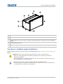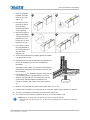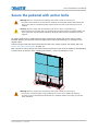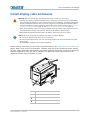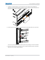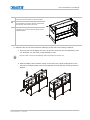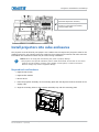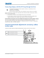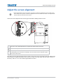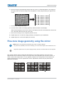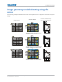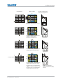
1
Installation and Setup Manual 020-101248-02 Entero HB Front-Access Cube Installation and Setup Manual 020-101248-02 Entero HB Front-Access Cube NOTICES COPYRIGHT AND TRADEMARKS Copyright © 2015 Christie Digital Systems USA, Inc. All rights reserved. All brand names and product names are trademarks, registered trademarks or trade names of their respective holders. GENERAL Every effort has been made to ensure accuracy, however in some cases changes in the products or availability could occur which may not be reflected in this document. Christie reserves the right to make changes to specifications at any time without notice. Performance specifications are typical, but may vary depending on conditions beyond Christie's control such as maintenance of the product in proper working conditions. Performance specifications are based on information available at the time of printing. Christie makes no warranty of any kind with regard to this material, including, but not limited to, implied warranties of fitness for a particular purpose. Christie will not be liable for errors contained herein or for incidental or consequential damages in connection with the performance or use of this material. Canadian manufacturing facility is ISO 9001 and 14001 certified. WARRANTY Products are warranted under Christie’s standard limited warranty, the complete details of which are available by contacting your Christie dealer or Christie. In addition to the other limitations that may be specified in Christie’s standard limited warranty and, to the extent relevant or applicable to your product, the warranty does not cover: a. Problems or damage occurring during shipment, in either direction. b. Projector lamps (See Christie’s separate lamp program policy). c. Problems or damage caused by use of a projector lamp beyond the recommended lamp life, or use of a lamp other than a Christie lamp supplied by Christie or an authorized distributor of Christie lamps. d. Problems or damage caused by combination of a product with non-Christie equipment, such as distribution systems, cameras, DVD players, etc., or use of a product with any non-Christie interface device. e. Problems or damage caused by the use of any lamp, replacement part or component purchased or obtained from an unauthorized distributor of Christie lamps, replacement parts or components including, without limitation, any distributor offering Christie lamps, replacement parts or components through the internet (confirmation of authorized distributors may be obtained from Christie). f. Problems or damage caused by misuse, improper power source, accident, fire, flood, lightening, earthquake or other natural disaster. g. Problems or damage caused by improper installation/alignment, or by equipment modification, if by other than Christie service personnel or a Christie authorized repair service provider. h. Problems or damage caused by use of a product on a motion platform or other movable device where such product has not been designed, modified or approved by Christie for such use. i. Problems or damage caused by use of a projector in the presence of an oil-based fog machine or laser-based lighting that is unrelated to the projector. j. For LCD projectors, the warranty period specified in the warranty applies only where the LCD projector is in “normal use” which means the LCD projector is not used more than 8 hours a day, 5 days a week. k. Except where the product is designed for outdoor use, problems or damage caused by use of the product outdoors unless such product is protected from precipitation or other adverse weather or environmental conditions and the ambient temperature is within the recommended ambient temperature set forth in the specifications for such product. l. Image retention on LCD flat panels. m.Defects caused by normal wear and tear or otherwise due to normal aging of a product. The warranty does not apply to any product where the serial number has been removed or obliterated. The warranty also does not apply to any product sold by a reseller to an end user outside of the country where the reseller is located unless (i) Christie has an office in the country where the end user is located or (ii) the required international warranty fee has been paid. The warranty does not obligate Christie to provide any on site warranty service at the product site location. PREVENTATIVE MAINTENANCE Preventative maintenance is an important part of the continued and proper operation of your product. Please see the Maintenance section for specific maintenance items as they relate to your product. Failure to perform maintenance as required, and in accordance with the maintenance schedule specified by Christie, will void the warranty. REGULATORY The product has been tested and found to comply with the limits for a Class A digital device, pursuant to Part 15 of the FCC Rules. These limits are designed to provide reasonable protection against harmful interference when the product is operated in a commercial environment. The product generates, uses, and can radiate radio frequency energy and, if not installed and used in accordance with the instruction manual, may cause harmful interference to radio communications. Operation of the product in a residential area is likely to cause harmful interference in which case the user will be required to correct the interference at the user’s own expense. CAN ICES-3 (A) / NMB-3 (A) 이 기기는 업무용 (A 급 ) 으로 전자파적합등록을 한 기기이오니 판매자 또는 사용자는 이점을 주의하시기 바라며 , 가정 외의 지역에서 사용하는 것을 목적 으로 합니다 . Environmental The product is designed and manufactured with high‐quality materials and components that can be recycled and reused. This symbol means that electrical and electronic equipment, at their end‐of‐life, should be disposed of separately from regular waste. Please dispose of the product appropriately and according to local regulations. In the European Union, there are separate collection systems for used electrical and electronic products. Please help us to conserve the environment we live in! Content Introduction . . . . . . . . . . . . . . . . . . . . . . . . . . . . . . . . . . . . . . . . . . . . . . . . . 7 Additional resources . . . . . . . . . . . . . . . . . . . . . . . . . . . . . . . . . . . . . . . . . . . . . .7 Safety precautions . . . . . . . . . . . . . . . . . . . . . . . . . . . . . . . . . . . . . . . . . . . . . . .8 Cube Installation and Setup . . . . . . . . . . . . . . . . . . . . . . . . . . . . . . . . . . . . . 9 Stacking limitations . . . . . . . . . . . . . . . . . . . . . . . . . . . . . . . . . . . . . . . . . . . . . .9 Components and hardware . . . . . . . . . . . . . . . . . . . . . . . . . . . . . . . . . . . . . . . . .9 Recommended installation tools . . . . . . . . . . . . . . . . . . . . . . . . . . . . . . . . . . . . . 11 Install pedestals . . . . . . . . . . . . . . . . . . . . . . . . . . . . . . . . . . . . . . . . . . . . . . . . 11 Construct a multiple pedestal platform . . . . . . . . . . . . . . . . . . . . . . . . . . . . . . 12 Secure the pedestal with anchor bolts . . . . . . . . . . . . . . . . . . . . . . . . . . . . . . . . . 14 Install display cube enclosures . . . . . . . . . . . . . . . . . . . . . . . . . . . . . . . . . . 15 Secure the cubes with tie backs . . . . . . . . . . . . . . . . . . . . . . . . . . . . . . . . . . . 18 (Optional) Remove the cube spacers . . . . . . . . . . . . . . . . . . . . . . . . . . . . . . . . . . 19 Projector Installation and Setup . . . . . . . . . . . . . . . . . . . . . . . . . . . . . . . . . 20 Unpack the projector . . . . . . . . . . . . . . . . . . . . . . . . . . . . . . . . . . . . . . . . . . . . 20 Rotate the electronic module . . . . . . . . . . . . . . . . . . . . . . . . . . . . . . . . . . . . . . . 21 Install the motorized adjustment accessory . . . . . . . . . . . . . . . . . . . . . . . . . . . . . 22 Install projectors into cube enclosures . . . . . . . . . . . . . . . . . . . . . . . . . . . . . . . . . 24 Tips for running external cables to the displays . . . . . . . . . . . . . . . . . . . . . . . . . . 25 Connect AC . . . . . . . . . . . . . . . . . . . . . . . . . . . . . . . . . . . . . . . . . . . . . . . . . . . 25 Connect the displays . . . . . . . . . . . . . . . . . . . . . . . . . . . . . . . . . . . . . . . . . . . . . 26 Connecting displays with RS232 cables . . . . . . . . . . . . . . . . . . . . . . . . . . . . . . 26 Connecting displays with Ethernet cables . . . . . . . . . . . . . . . . . . . . . . . . . . . . . 26 Connecting displays with the DVI loop-through interface . . . . . . . . . . . . . . . . . . 28 Connect motorized adjustment accessory cables to the cube . . . . . . . . . . . . . . . . . 28 Install and Align Screens . . . . . . . . . . . . . . . . . . . . . . . . . . . . . . . . . . . . . . 29 Determine the optimal gap between screens . . . . . . . . . . . . . . . . . . . . . . . . . . . . 29 Install the screen . . . . . . . . . . . . . . . . . . . . . . . . . . . . . . . . . . . . . . . . . . . . . . . 31 Adjust the screen alignment . . . . . . . . . . . . . . . . . . . . . . . . . . . . . . . . . . . . . . . . 32 Align the screen latch . . . . . . . . . . . . . . . . . . . . . . . . . . . . . . . . . . . . . . . . . . . . 34 Open the front access screen . . . . . . . . . . . . . . . . . . . . . . . . . . . . . . . . . . . . . . . 36 Lift the released screen . . . . . . . . . . . . . . . . . . . . . . . . . . . . . . . . . . . . . . . . . 37 Entero HB Front-Access Cube Installation and Setup Manual 020-101248-02 Rev. 1 (06-2015) 5 Close the front access screen . . . . . . . . . . . . . . . . . . . . . . . . . . . . . . . . . . . . . 37 Turn the projector on . . . . . . . . . . . . . . . . . . . . . . . . . . . . . . . . . . . . . . . . . . . . 38 IR remote . . . . . . . . . . . . . . . . . . . . . . . . . . . . . . . . . . . . . . . . . . . . . . . . . . . . 39 Adjust the Image . . . . . . . . . . . . . . . . . . . . . . . . . . . . . . . . . . . . . . . . . . . . 40 Adjustment tips . . . . . . . . . . . . . . . . . . . . . . . . . . . . . . . . . . . . . . . . . . . . . . . . 40 Adjust lens focus . . . . . . . . . . . . . . . . . . . . . . . . . . . . . . . . . . . . . . . . . . . . . . . 40 Adjust image geometry using the 6-axis adjuster . . . . . . . . . . . . . . . . . . . . . . . . . 42 Fine–tune image geometry using the mirror . . . . . . . . . . . . . . . . . . . . . . . . . . . . . 44 Mirror adjustment screws . . . . . . . . . . . . . . . . . . . . . . . . . . . . . . . . . . . . . . . 45 Barrel and pincushion distortion . . . . . . . . . . . . . . . . . . . . . . . . . . . . . . . . . . . 45 Image geometry troubleshooting using the mirror . . . . . . . . . . . . . . . . . . . . . . . . . 46 Configure the display wall . . . . . . . . . . . . . . . . . . . . . . . . . . . . . . . . . . . . . 48 Connect to power . . . . . . . . . . . . . . . . . . . . . . . . . . . . . . . . . . . . . . . . . . . . . . . 48 Connect AC . . . . . . . . . . . . . . . . . . . . . . . . . . . . . . . . . . . . . . . . . . . . . . . . . . . 48 Enable power . . . . . . . . . . . . . . . . . . . . . . . . . . . . . . . . . . . . . . . . . . . . . . . . 49 Disable power . . . . . . . . . . . . . . . . . . . . . . . . . . . . . . . . . . . . . . . . . . . . . . . 49 Map and number the display . . . . . . . . . . . . . . . . . . . . . . . . . . . . . . . . . . . . . . . 49 Unmap the display . . . . . . . . . . . . . . . . . . . . . . . . . . . . . . . . . . . . . . . . . . . . . . 51 Configure network settings . . . . . . . . . . . . . . . . . . . . . . . . . . . . . . . . . . . . . . . . 51 Connect the displays to WiFi (WiFi model only) . . . . . . . . . . . . . . . . . . . . . . . . . . . 52 Motorized adjustment accessory LEDs . . . . . . . . . . . . . . . . . . . . . . . . . . . . . . . . . 55 Preventative Maintenance . . . . . . . . . . . . . . . . . . . . . . . . . . . . . . . . . . . . . 56 Clean the mirror . . . . . . . . . . . . . . . . . . . . . . . . . . . . . . . . . . . . . . . . . . . . . . . . 56 Remove water droplet rings, marks, and other surface stains . . . . . . . . . . . . . . . 56 Remove finger prints Clean the screen . . . . . . . . . . . . . . . . . . . . . . . . . . . . . . . . . . . . . . . . . . 57 . . . . . . . . . . . . . . . . . . . . . . . . . . . . . . . . . . . . . . . . . . . . . . . 57 Clean the projection lens . . . . . . . . . . . . . . . . . . . . . . . . . . . . . . . . . . . . . . . . . . 58 dust from the projection lens . . . . . . . . . . . . . . . . . . . . . . . . . . . . . . . . . . . . 58 Remove fingerprints, smudges, or oil from the projection lens . . . . . . . . . . . . . . 58 Specifications . . . . . . . . . . . . . . . . . . . . . . . . . . . . . . . . . . . . . . . . . . . . . . . 59 Entero HB Front-Access Cube Installation and Setup Manual 020-101248-02 Rev. 1 (06-2015) 6 Introduction This manual provides instructions for installing a Christie front access cube display system, which is comprised of a cube enclosures, projection light engines, display screens, and cube pedestals. The manual is intended for technicians with experience installing display systems. To avoid personal injury or damage to the display system, read this information thoroughly before installing the Entero HB pedestals, projectors, and cube enclosure. • Read these instructions. • Keep these instructions. • Heed all warnings. • Follow all instructions. i • Ambient temperature must stay below 35° C (95° F). For best performance and reliability, an ambient temperature of less than 25° C is recommended. • Keep the projector away from all devices radiating electromagnetic energy. For example, motors, transformers, speakers, power amplifiers, and elevators. Install the components of the Entero cube in the following order: 1. Install the pedestals. See Install pedestals on page 11. 2. Install the cubes. See Install display cube enclosures on page 15. 3. Install the projector. See Projector Installation and Setup on page 20. 4. Install the screen on each cube. See Install and Align Screens on page 29. 5. Adjust the image on the screen. See Adjust the Image on page 40. Additional resources • Entero HB Serial Command Reference Guide (P/N: 020-101355-xx) • Entero HB Service Manual (P/N: 020-100982-xx) • Entero HB Software User Manual (P/N: 020-100981-xx) Entero HB Front-Access Cube Installation and Setup Manual 020-101248-02 Rev. 1 (06-2015) 7 Introduction • Installing a Projector into a Custom Structure with Direct Throw Orientation Instruction Sheet (P/N: 020-101345-xx) Safety precautions Observe these important safety rules to avoid personal injury or damage to the projector or display cubes: Warning! Failure to comply with the following could result in death or serious injury. • Tip Load! The maximum stacking limitation is three cubes high in a minimum two column display wall. Cubes may be stacked up to five cubes high with a custom pedestal. The display wall must be properly anchored anytime the wall is two rows or higher to prevent tipping and provide stability. Use all the hardware provided to fasten the display cubes to the support structure. See Secure the pedestal with anchor bolts on page 14 and Secure the cubes with tie backs on page 18. • Tip Load! Screens must not be opened without the pedestals being bolted together and bolted to the floor, without the cubes being bolted together and tied back to the wall, and without the projector installed. • The front access cubes must be assembled in the following order: 1) Pedestals must be installed, bolted together, leveled, and bolted to the floor. 2) Cubes are installed, bolted together, and tied back to the wall. 3) Projectors are installed. 4) Screens are installed. • Disconnect the AC cord before disconnecting any projector components. Caution! Failure to comply with the following could result in minor or moderate injury. • Do not look directly into the projector lens. The high brightness of this projector could cause permanent eye damage. For protection, keep all projector shielding intact during operation. • Lift equipment must be used to lift the display cubes into position on rows two or higher. A crew of two or more can lift a display cube into position on the first row. • Mount the projector in a Christie display cube or to a sturdy, flat surface that fits the entire projector. Use all four mounting points to secure the projector to the surface. • Always power down and disconnect/disengage all power sources to the projector before servicing or cleaning. • Stand at least 3 feet from the screen when unlocking it through the on screen display. The screen is spring loaded and once unlocked it slides out. • Open the front access panel from the side of the screen to ensure the screen has enough distance to swing out from the cube. Notice. Failure to comply with the following may result in property damage. • Maintain a minimum clearance of 2.5 cm (1.0”) around the projector for air circulation and 7.5 cm (3”) clearance for cable connections to the input panel. Insufficient clearance can cause the projector to overheat during operation or place undue stress on source connections. • This projector must be operated in an environment that meets the operating range specification, as listed in Specifications on page 59. Entero HB Front-Access Cube Installation and Setup Manual 020-101248-02 Rev. 1 (06-2015) 8 Cube Installation and Setup Notice. Failure to comply with the following may result in property damage. • Only qualified installers should attempt installation of a Christie display wall. Stacking limitations Caution! Failure to comply with the following could result in minor or moderate injury. • Tip Load! The maximum stacking limitation is three cubes high in a minimum two column display wall. Cubes may be stacked up to five cubes high with a custom pedestal. • The display wall must be properly anchored anytime the wall is two rows or higher to prevent tipping and provide stability. Use all the hardware provided to fasten the display cubes to the support structure. See Secure the pedestal with anchor bolts on page 14 and Secure the cubes with tie backs on page 18. • When stacking display cubes, they must be installed on a level surface. If the surface is not level, the stacked cubes could tip over and cause damage to the cubes or personal injury. Stacking limitations apply to all the display cube models. Christie recommends using tiebacks and lag bolts to secure the display wall. For details, see Secure the pedestal with anchor bolts on page 14 and Secure the cubes with tie backs on page 18. Components and hardware All major components required to assemble a complete display cube are packaged and shipped separately to the installation site. This includes the display cube enclosure, projector, display screen, and pedestal. Check the contents of your shipment against the list below to make sure that you have all the necessary hardware. Hardware is listed by component and applies to all models unless otherwise noted. Cube enclosures • M6 75 mm hex screws (Qty. 10) Entero HB Front-Access Cube Installation and Setup Manual 020-101248-02 Rev. 1 (06-2015) 9 Cube Installation and Setup • M6 18 mm flat washers (Qty. 20) • M6 lock washers (Qty. 10) • M6 hex nuts (Qty. 10) • M6 60 mm hex screws (Qty. 2) • M6 24 mm flat washers (Qty. 4) • M4 hex screws (Qty. 6) • Motorized Adjustment Accessory cube extension • Cable covers • Panel plug Screens • M6 screws (Qty. 8) • M8 set screws (Qty. 4) Pedestals • M6 75 mm hex screws (Qty. 4) • M6 flat washers (Qty. 8) • M6 lock washers (Qty. 4) • M6 hex nuts (Qty. 4) • Cable covers (Qty. 4) • Anchor bolts (Qty. 4) Projector • M6 cap screws (Qty. 8) • M6 flat washers (Qty. 8) Entero HB projectors • Each display wall requires a User Kit (P/N: 139-100102-xx). One User Kit is provided with each order, and two are provided with every four or more units ordered. i • Power cord • User Kit (P/N:139-100102-xx), which includes: • • Entero HB Front-Access Cube Installation and Setup Manual (this manual, P/N: 020101248-02) • IR remote control with two AA batteries • Ball drivers: 13 mm (long), 8 mm, 5 mm, 4 mm (long), 2 mm, 2.5 mm (long) A pair of lint–free gloves (required for mirror and screen handling) Entero HB Front-Access Cube Installation and Setup Manual 020-101248-02 Rev. 1 (06-2015) 10 Cube Installation and Setup Motorized adjustment accessory • Lower module • Upper module • DB15 harness • DB9 harness • Teflon washers (Qty. 2) • Adjuster posts (Qty. 2) Recommended installation tools • Level • 10 mm hex wrench or socket driver • M6 hex driver • M8 hex driver • 5 mm ball driver (provided with the User Kit) • 4 mm ball driver (provided with the User Kit) • Adjustable wrench • Torque wrench • #2 Phillips™ screwdriver Install pedestals When you install Christie display cubes, Christie recommends that you use a Christie pedestal designed to support the maximum stacking limit of the display cubes. Alternatively, custom designed pedestals can be used; however, the designer and installer must make sure the custom structure meets performance and safety requirements. Notice. Failure to comply with the following may result in property damage. • To ensure there is enough space for the cube enclosures, the pedestals must be installed a minimum of four inches from the wall. 1. Lift the cardboard packaging off of the cube enclosures and pedestals. Do not cut the packaging with a knife. 2. Remove the back panels and set aside in a location where the panels will not be damaged. The panels are secured with two sprint release clips each. Press down on the clips and tilt the top of the panel out, and lift the panel away. Entero HB Front-Access Cube Installation and Setup Manual 020-101248-02 Rev. 1 (06-2015) 11 Cube Installation and Setup B B C C B B D A A A A E A To secure pedestals to each other, connect at the four points on each side panel. B To secure display cubes to the pedestal, connect at the two points at the back and the two points at the front. C To secure display cubes, connect at the two points on the support bracket. (All models except the 50SXGAFA pedestal) D Front Panel (faces the room) E Adjustable feet (Qty. 4) Construct a multiple pedestal platform Before starting, check that you have all the required hardware. See Components and hardware on page 9. Caution! Failure to comply with the following could result in minor or moderate injury. • Make sure that the appropriately rated lifting equipment and a minimum of two people are available for installation. • Mount the pedestals on a permanent, hard surface such as a concrete floor. Elevated surfaces, such as wood platforms are not recommended. i • Always start at the center and work outward. Make sure each pedestal is level. • Do not fully tighten the hardware that attaches pedestals together until you have completed all of your adjustments and installed all of the pedestals. Entero HB Front-Access Cube Installation and Setup Manual 020-101248-02 Rev. 1 (06-2015) 12 Cube Installation and Setup 1. Slide two pedestals together and align the front and rear edges. (A) A B C D 2. To make sure that the feet are flat to the floor apply downward pressure on the pedestal. 3. Match the height of adjacent pedestals. To raise or lower the pedestal, turn the bottom nut on each pedestal foot. (B) 4. Use a level to verify that the pedestal is level on all sides and with the other pedestal. (B) 5. To lock the pedestal foot in position tighten the middle nut against the top nut. 6. Check that you can see threads inside the pedestal, at the corner bracket where the foot is installed as illustrated. If threads are not visible, you have over-extended the pedestal foot. Readjust the foot before continuing with the installation. 7. Hand-tighten the two pedestals together using four M6 x 75 mm hex screws, eight flat washers, four lock washers, and four M6 hex nuts. Make sure that the vertical seam between adjacent pedestals is as narrow as possible and uniform from top to bottom. (C) 8. Slide the next pedestal into position and repeat steps 2 to 7. (D) 9. Confirm that the platform is level and that all of the rear edges of the pedestals are aligned. 10. To secure the pedestals, torque the loose hardware to 98 in-lb. 11. Use a level to confirm that the platform structure is level from end-to-end. Notice. Failure to comply with the following may result in property damage. • The pedestals must be perfectly level, or there may be difficulties when installing the cubes and screens. Entero HB Front-Access Cube Installation and Setup Manual 020-101248-02 Rev. 1 (06-2015) 13 Cube Installation and Setup Secure the pedestal with anchor bolts Warning! Failure to comply with the following could result in death or serious injury. • Tip Load! Screens must not be opened if the pedestals are not bolted together and bolted to the floor, if the cubes are not bolted together and tied back to the wall, and if the projector is not installed. Caution! Failure to comply with the following could result in minor or moderate injury. • External support for a display wall must be designed and implemented by a qualified installer and must comply with local area safety standards. All display walls must have permanent external supports. All display walls must be supported externally anytime the display wall is two rows or higher. External support prevents the wall from tipping and causing personal injury or damage to the display cubes. Christie requires that both anchor bolts and tie backs are used to support the display wall. See Secure the cubes with tie backs on page 18. Each column of cubes requires four anchor bolts. Each anchor bolt must be capable of withstanding a pullout force of 500 lbs. After installing the anchors, verify the pedestal is level. Warning! Failure to comply with the following could result in death or serious injury. • The amount of external support required depends on the size of the display wall. Support structures must be designed and implemented by a qualified installer and comply to local area safety standards. Entero HB Front-Access Cube Installation and Setup Manual 020-101248-02 Rev. 1 (06-2015) 14 Cube Installation and Setup Install display cube enclosures Warning! Failure to comply with the following could result in death or serious injury. • Tip Load! The maximum stacking limitation is three cubes high in a minimum two column display wall. Cubes may be stacked up to five cubes high with a custom pedestal. The display wall must be properly anchored anytime the wall is two rows or higher to prevent tipping and provide stability. Use all the hardware provided to fasten the display cubes to the support structure. See Secure the pedestal with anchor bolts on page 14 and Secure the cubes with tie backs on page 18. • When stacking display cubes, they must be installed on a level surface. If the surface is not level, the stacked cubes could tip over and cause damage to the cubes or personal injury. • Appropriate lift equipment must be used to lift display cubes onto rows two or higher. Notice. Failure to comply with the following may result in property damage. • Do not cut the protective film off the mirror with a knife. • Do not touch the optical mirror with your bare hands. Fingerprints left on the surface can impact image quality. • Do not bump or scratch the mirror during unpacking. Before starting, check that you have all the required hardware. See Components and hardware on page 9. With a crew of two or more people, complete each row of cube enclosures before starting the next. Proper alignment reduces issues with image geometry and makes sure that the wall has a seamless appearance. Once the wall is installed, it is difficult and time–consuming to fix an alignment problem near the bottom of a wall. D B C A A Cable covers B 3 rear access panels C Rear access panel spring release clip D Panel plugs Entero HB Front-Access Cube Installation and Setup Manual 020-101248-02 Rev. 1 (06-2015) 15 Cube Installation and Setup 1. To allow for a smaller package, the rear panel of the cube enclosure has the Motorized adjustment accessory panel extension installed in reverse. Remove the panel extension from the inside of the rear panel, and reinstall it on the outside. 2. On each side of the cube enclosure, remove the silver screw located above the screen latch. The screw is used to hold the screen bracket in place during shipping, and can be discarded. 3. Determine where the cables connecting the cubes will pass through the panels, and install a cable cover over all other exposed openings. Entero HB Front-Access Cube Installation and Setup Manual 020-101248-02 Rev. 1 (06-2015) 16 Cube Installation and Setup A To fasten side-by-side display cubes together, connect at the four points on each side panel. B To fasten the display cube to the pedestal or to the cube below, connect at the two points at the back and the two points at the front. C To fasten the display cube to the pedestal or cube below it, connect at the two points on the support bracket. A B A C B C A B A 4. Install the first row of cube enclosures starting from the center and working outwards. a. From the front of the display structure, lift the cube enclosure over the pedestal or cube row and lower it in the center of the pedestal or cube. i • A crew of two or more can lift a display cube into position on the first row. b. With the display cube enclosure resting on the lower level, adjust its alignment so the side and rear edges between the two components are flush and the mounting holes are aligned. Entero HB Front-Access Cube Installation and Setup Manual 020-101248-02 Rev. 1 (06-2015) 17 Cube Installation and Setup c. To secure the cube to the pedestal or cube in the lower level, use six M6 x 75 mm screws with washers and hex nuts. To allow for small adjustments, do not fully tighten the mounting hardware identified in step 4. i • For a single, stand-alone unit, tighten the hardware until components are fully secured, then proceed to Secure the cubes with tie backs on page 18. d. Use four M6 x 75 mm screws with washers and hex nuts to attach the cube to the one adjacent to it. Hand tighten the mounting hardware. Adjustment screws x10 5. Check the alignment between all of the display cubes and make adjustments as required. All cubes must be aligned vertically and horizontally. 6. Before installing another row of display cubes, tighten all mounting hardware between the display cubes and pedestals. Tighten hardware to a minimum torque setting of 11.1 Nm / 98 lbf–in. 7. To add the next row of cube enclosures, repeat steps 1 to 6. Secure the cubes with tie backs Warning! Failure to comply with the following could result in death or serious injury. • Tip Load! Screens must not be opened if the pedestals are not bolted together and bolted to the floor, if the cubes are not bolted together and tied back to the wall, and if the projector is not installed. Caution! Failure to comply with the following could result in minor or moderate injury. • External support for a display wall must be designed and implemented by a qualified installer and must comply to local area safety standards. All display walls must have permanent external supports. Failure to comply could result in minor or moderate injury. All display walls must be supported externally anytime the display wall is two rows or higher. External support prevents the wall from tipping and causing personal injury or damage to the display cubes. Christie requires that both anchor bolts and tie backs are used to support the display wall. See Secure the pedestal with anchor bolts on page 14. Every column of cubes requires one tie back. Each tie back must be capable of withstanding a pullout force of 500 lbs. Entero HB Front-Access Cube Installation and Setup Manual 020-101248-02 Rev. 1 (06-2015) 18 Cube Installation and Setup Warning! Failure to comply with the following could result in death or serious injury. • The amount of external support required depends on the size of the display wall. Support structures must be designed and implemented by a qualified installer and comply to local area safety standards. (Optional) Remove the cube spacers For the front-access screens to be opened without interference from the surrounding screens, each cube includes spacers that leave a nominal space between the screens. The spacers between the top of one pedestal and the bottom of the cube create a gap that allows for proper screen access. After the display wall cubes are installed and secured, you may decide to remove the spacers on the exposed columns. The spacers are located along the top and sides of the cube and pedestals, as identified in the following diagram. To remove the spacers, remove the two screws holding each spacer in place. Entero HB Front-Access Cube Installation and Setup Manual 020-101248-02 Rev. 1 (06-2015) 19 Projector Installation and Setup The projector is designed for installation in a Christie cube display or a custom display structure. The projection head is intended to be used in an upright position or 90° to normal for cube mounting. i • Ambient temperature must stay below 35° C (95° F). For best performance and reliability, an ambient temperature of less than 25° C is recommended. • Keep the projector away from all devices radiating electromagnetic energy. For example, motors, transformers, speakers, power amplifiers, and elevators. Unpack the projector Caution! Failure to comply with the following could result in minor or moderate injury. • The projector should be lifted by two people. • Use the designated handles to help lift and support the projector. • Use a stable cart to transport the projector. Notice. Failure to comply with the following may result in property damage. • Do not place the projector onto a surface with the line cord retainer side down. Failure to comply may result in damage to the line cord retainer. i • The projector is shipped inverted upside down inside the packaging box. • Christie recommends you keep the packaging in the event that a projector must be returned to the factory for servicing. 1. Remove the top foam from the box and place it on a stable surface. 2. Remove the projector from the box, invert it so the lens is facing up, and place it onto the top foam. 3. Remove the foam piece wedged between the tray and the light module. Entero HB Front-Access Cube Installation and Setup Manual 020-101248-02 Rev. 1 (06-2015) 20 Projector Installation and Setup 4. Loosen the four screws securing the green knob, and turn the green adjustment knob on the 6axis adjuster CW or CCW to relieve the pressure on the foam piece. Adjustment Knob Hex key Loosen 4 screws Rotate the electronic module To see the OLED status display and have the connectors face the front of the cube, turn the Electronic Module (EM) 180 degrees. 1. Unplug all cables from the Electronic Module. 2. Remove the four screws attaching the EM bracket to the tray. 3. Rotate the module 180 degrees, and place the EM bracket back onto the tray. 4. Replace the four screws. 5. Reattach all cables to the Electronic Module. Entero HB Front-Access Cube Installation and Setup Manual 020-101248-02 Rev. 1 (06-2015) 21 Projector Installation and Setup Install the motorized adjustment accessory The Motorized Adjustment Accessory is an attachment to the engine comprised of two pieces, which control the 6-axis adjuster knobs through the WebUI or On Screen Display (OSD). Top piece of the Motorized Adjustment Accessory Bottom piece of the Motorized Adjustment Accessory 1. Ensure the lock screws for each adjustment knob are loosened. Use the 5 mm hex key provided to loosen the M6 lock screws and a 2 mm hex key (not provided) to loosen the collar lock screws. 2. Install the Teflon washers and posts beside the top level of 6-axis adjuster, ensuring the holes of the posts are facing up. 3. Remove the hex key. 4. Insert the bottom piece of the Motorized Adjustment Accessory into the matching 6-axis adjustor knobs. Entero HB Front-Access Cube Installation and Setup Manual 020-101248-02 Rev. 1 (06-2015) 22 Projector Installation and Setup 5. Push the two connectors until they snap into the engine and secure the bottom piece in place on the projector. The connection points for the bottom piece of the Motorized Adjustment Accessory are highlighted. 6. Install the top piece of the Motorized Adjustment Accessory into the matching 6-axis adjustor knobs, ensuring the bracket slides over the posts. 7. Push the pins into the holes of the posts until they are fully seated and the top piece is secured. The connection points for the top piece of the Motorized Adjustment Accessory are highlighted. 8. Connect the cables between the Motorized Adjustment Accessory and the light engine. Entero HB Front-Access Cube Installation and Setup Manual 020-101248-02 Rev. 1 (06-2015) 23 Projector Installation and Setup A B A Connects the interlock switches and the Motorized Adjustment Accessory. B Connects the Motorized Adjustment Accessory to the Electronics Module, using the DB15 cable. Install projectors into cube enclosures The projector must be lifted by two people. Use a stable cart to transport the projector. Refer to the drawings given for your specific projector model for the mounting hole location and other technical information and restrictions which may be useful during installation. Notice. Failure to comply with the following may result in property damage. • The projector vents provide ventilation, both for intake and exhaust. Do not block or cover these openings. Do not install the projector near a radiator or heat register, or within an enclosure. Failure to comply may result in equipment damage. Required tools and hardware • Eight M6 Cap screws • Eight M6 flat washers • M6 hex driver 1. Place the projector assembly on the mounting plate with the adjuster knobs at the back of the display cube. 2. Align the mounting holes on the projector assembly tray with the mounting plate. Entero HB Front-Access Cube Installation and Setup Manual 020-101248-02 Rev. 1 (06-2015) 24 Projector Installation and Setup i • The illustration above shows the mounting plate holes and projector assembly from the front of the cube for ease of viewing. • The cube model determines the type and height of the mounting plate. 3. Install the eight M6 cap screws and flat washers. Tighten all screws to a torque setting of 4.5 Nm/40 lbf–in. Tips for running external cables to the displays All Christie cubes have channels for cable routing. Cable covers are included for external cube walls. • Route cables across the display wall through the pedestals. • Always keep cables to the required length to avoid excess. • Run cables through the horizontal and vertical cable channels (see image). • When cabling is complete, bundle the cables with zip ties. Zip ties are not included with the projector. • Avoid putting any strain on the cables and connectors. Connect AC Caution! Failure to comply with the following could result in minor or moderate injury. • Use only an AC supply within the specified voltage and power range. Do not attempt operation if the AC power source is not within the rated voltage range, as specified on the license label, found on the projector tray. i • Make sure the array is connected to a wall breaker with max. 20A. • Can be connected to IT power distribution. Each display is supplied with a power cord appropriate for your region. 1. Plug one end of the power cord into the AC receptacle on the power module. 2. Plug the other end of the power cord into a grounded AC outlet. Entero HB Front-Access Cube Installation and Setup Manual 020-101248-02 Rev. 1 (06-2015) 25 Projector Installation and Setup Connect the displays i • The optional DVI-D interface supports a secondary or redundant input source. This feature is sold separately. • The two USB ports are not supported. For future release. Sources connect to the front input panel on the electronic module. Control RS232 ETH1/USB1 ETH2/USB2 Output Source DVI-D IN1 DVI-D Loopout Power Optional DVI–D interface card Connecting displays with RS232 cables RS232 is used to communicate with a third– party controller using serial commands. Connect a serial cable between the controller and the RS232 port on the electronic module. Controller 2 23 RS Connecting displays with Ethernet cables i • DVI-D Loopout and Ethernet daisy chain configurations support a maximum of 25 displays. In the Ethernet network configurations illustrated below, each display communicates with neighboring displays within an array to achieve brightness and color uniformity across all displays through ArraySync. To add a display to an Ethernet network: 1. Using an Ethernet hub, connect a standard CAT5 Ethernet cable to the ETH2 connector on each display. - or - Entero HB Front-Access Cube Installation and Setup Manual 020-101248-02 Rev. 1 (06-2015) 26 Projector Installation and Setup Connect a standard CAT5 Ethernet cable between the ETH1 connector of the first display’s electronic module and the ETH2 connector of the next display’s connector. 2. When Ethernet is connected it uses DHCP to acquire the IP address; however, the IP address can be manually setup through the On Screen Display (OSD) or the Web User Interface (WebUI). Ethernet network using hub With this configuration, one benefit is that if there is a projector failure in the array, the remaining projectors remain synchronized across the array. The disadvantages of this configuration is that an external switch is required, and there is more cabling required. Ethernet network using daisy chain With the daisy chain configuration, an external switch is not required and there is less cabling; however if there is a projector failure in this configuration, the display wall is separated into two independent arrays for ArraySync color and brightness management. Notice. Failure to comply with the following may result in property damage. • Do not connect the last display in the Ethernet daisy chain to the first display or the Ethernet hub, as it creates a network loop and may cause displays to be undetected in the WebUI. Entero HB Front-Access Cube Installation and Setup Manual 020-101248-02 Rev. 1 (06-2015) 27 Projector Installation and Setup Connecting displays with the DVI loop-through interface i • The optional DVI Loop-through interface supports a secondary or redundant input source. This feature is sold separately. • Analog inputs are not supported. • DVI Loop-through and Ethernet daisy chain configurations support a maximum of 25 displays. Source connections are made to the input panel of the electronic module. Each input is clearly labeled for easy identification. • Use the DVI–I connector to connect digital video devices to the display. • Use DVI cables to connect from each source to each display. Sources are typically from a display wall processor with multiple output channels, one from each display. If the installation requires one source to be displayed and scaled across multiple displays, connect the source to the first display then use the DVI Out of that display to connect to the DVI-D Loopout of the next display. Repeat for each display, and make sure that Tiling Mode is enabled. The display wall can be configured to operate in independent mode or tile mode. In independent mode the input video is not daisy–chained. Connect motorized adjustment accessory cables to the cube Connect the cables between the Motorized Adjustment Accessory and the cube enclosure. C C Connects the harness from the solenoids to the Motorized Adjustment Accessory. D, E Connects the top and bottom pieces of the Motorized Adjustment Accessory. D E Entero HB Front-Access Cube Installation and Setup Manual 020-101248-02 Rev. 1 (06-2015) 28 Install and Align Screens Determine the optimal gap between screens Notice. Failure to comply with the following may result in property damage. • Read this entire section before installing the screens. • Remove the screen from the packaging to allow for acclimatization. • Store the screen in a low traffic area away from the installation to protect it from accidental tipping or scratching. • Let the screen stabilize to ambient site conditions for a minimum of 24 hours prior to installation on the cube. In an environment where the relative humidity is high, many days may be required before the screen is stabilized. • Wear the lint–free gloves provided in the user kit (P/N: 139-100102-xx) when handling the screens to prevent leaving fingerprints on the surface. i • Start with the center cube of the first row and work outwards. • Check that you have all the required hardware. See Components and hardware on page 9. As temperature and humidity vary, the acrylic screens acclimatize and can slightly expand or contract. The screen gap is a buffer designed to allow for the summation of both thermal and hygroscopic expansion rates. 1. Determine the level of control the environment has for both temperature and humidity fluctuations. 2. Add the recommended screen gap size from the thermal increase table and the hygroscopic increase table below. 3. Assemble the display wall with the resulting gap sizes. The gap cards included in the User Kits should be used during assembly. Two 0.5mm cards can be stacked to make a 1.0mm gap. Entero HB Front-Access Cube Installation and Setup Manual 020-101248-02 Rev. 1 (06-2015) 29 Install and Align Screens Thermal increase Thermal Increase (Degrees Celcius) Recommended Gap Size (mm) 50” 70” SX 70” HD 72” WU 0 0.1 0.1 0.1 0.1 2 0.1 0.2 0.2 0.2 4 0.2 0.3 0.4 0.4 6 0.4 0.5 0.5 0.5 8 0.5 0.6 0.7 0.7 10 0.6 0.8 0.9 0.9 12 0.7 1.0 1.1 1.1 14 0.8 1.1 1.2 1.2 16 0.9 1.3 1.4 1.4 18 1.0 1.4 1.6 1.6 20 1.2 1.6 1.8 1.8 Hygroscopic increase Hygroscopic Recommended Gap Size (mm) Increase (percent) 50” 70” SX 70” HD 72” WU 0 0.1 0.1 0.1 0.1 5 0.1 0.1 0.1 0.1 10 0.1 0.1 0.1 0.1 15 0.1 0.1 0.1 0.1 20 0.1 0.2 0.2 0.2 25 0.2 0.2 0.2 0.2 For example, Front Access 70" HD screens are stabilized to an environmental condition of 24°C and 60% relative humidity (RH) for a minimum of 24 hours. If the maximum environmental conditions for the screens will be 30°C and 80% RH, this requires a maximum increase of +6°C and +20% RH. Based on the information in the Thermal increase and Hygroscopic increase tables, a gap of 0.6 mm to allow for the thermal increase, and a gap of 0.2 mm for the hygroscopic increase. Including the nominal 1.7 mm gap between screens, the formula for calculating the required screen gap is: 1.7 mm + 0.6 mm + 0.2 mm = 2.5 mm Entero HB Front-Access Cube Installation and Setup Manual 020-101248-02 Rev. 1 (06-2015) 30 Install and Align Screens Install the screen Notice. Failure to comply with the following may result in property damage. • Store the screen in a low traffic area away from the installation to protect it from accidental tipping or scratching. • Let the screen stabilize to ambient site conditions for a minimum of 24 hours prior to installation on the cube. • Read this entire section before installing the screens. • Wear the lint–free gloves provided in the user kit (P/N: 139-100102-xx) when handling the screens to prevent leaving fingerprints on the surface. i • Start with the center cube of the first row and work outwards. • Check that you have all the required hardware. See Components and hardware on page 9. 1. Wearing the lint–free cotton gloves provided in the User Kit, remove the screen from the packaging. Stand the screen vertically with the outside of it against a clean wall, or on a clean flat surface with the outside of the screen facing down. A 2. Wearing lint–free cotton gloves, remove the protective film from the optical mirror and then from the back of the screen. 3. Working with a partner, lift the screen into position at the front of the display cube. Tilt and align the screen with the two top hinges on the cube, and hook the screen in place. (A) i • Always complete installing screens on the first row before starting onto the next row. B 4. Push the bottom of the screen bracket over the bottom latch, securing the screen. (B) 5. Check and correct alignment and screen gap issues before adding another screen. See Adjust the screen alignment on page 32. 6. To install additional screens in the row repeat steps 1 to 5. Work from the center outwards. 7. Check and correct alignment and screen gap issues before adding a row of screens. Misalignment is difficult to correct once all screens are in place. 8. As rows are added, adjust the screen depth adjustment screws to make sure the screen is flat. 9. Once the second row of screens has been installed, adjust the depth screws on the first row of screens. 10. Once the third row of screens has been installed, adjust the depth screws on the second row. 11. Continue until all rows have been completed. 12. After all cubes have been installed, make fine screen adjustments to ensure the screen gaps are even across the display wall. Entero HB Front-Access Cube Installation and Setup Manual 020-101248-02 Rev. 1 (06-2015) 31 Install and Align Screens Adjust the screen alignment i • These adjustments require two people: one person to make the adjustments on the inside of the frame and the other person to check the adjustments on the outside of the frame. The adjustments must be made to both sides of the screen. Check and correct alignment and screen gap issues before adding another screen. C A B C A For vertical adjustment, turn the screw to increase or decrease the height on that side of the screen. Use vertical adjustments to equalize the seams between the cubes. B For horizontal adjustment, turn the screw to move the screen to the left or right. C For depth adjustment, turn the screw in each corner of the screen clockwise to push the corresponding corner out from the cube body. Turn the screws counter-clockwise to pull in the corner of the screen. The desired screen alignment has all four sides of the screen lined up directly with the sides of the cube enclosure. Adjust both sides of the screen to make sure they align with the other screens in the array. There is a 1.7 mm nominal gap between screens. Entero HB Front-Access Cube Installation and Setup Manual 020-101248-02 Rev. 1 (06-2015) 32 Install and Align Screens If any adjustments are made to the horizontal or vertical alignment of the screen, you must adjust the screen latches as well to ensure the latches are correctly positioned to catch the screen when it is closed. See Align the screen latch on page 34. Alignment Issue Screen is to the right of the cube enclosure Resolution 1. Turn the horizontal alignment screw (B) on the left side of the screen counter clockwise with less than two turns. 2. Turn the horizontal alignment screw (B) on the right side of the screen clockwise with less than two turns. 3. Repeat the screw adjustments on each side until the screen and cube are aligned. Screen is to the left of the cube enclosure 1. Turn the horizontal alignment screw (B) on the right side of the screen clockwise with less than two turns. 2. Turn the horizontal alignment screw (B) on the left side of the screen counter clockwise with less than two turns. 3. Repeat the screw adjustments on each side until the screen and cube are aligned. Screen is above the cube enclosure 1. Turn the vertical alignment screw (A) on the left side of the screen counter clockwise. 2. Turn the vertical alignment screw (A) on the right side of the screen counter clockwise. 3. Repeat the screw adjustments on each side until the screen and cube are aligned. 4. Ensure the screen is level. Entero HB Front-Access Cube Installation and Setup Manual 020-101248-02 Rev. 1 (06-2015) 33 Install and Align Screens Alignment Issue Resolution Screen is below the cube enclosure 1. Turn the vertical alignment screw (A) on the left side of the screen clockwise. 2. Turn the vertical alignment screw (A) on the right side of the screen clockwise. 3. Repeat the screw adjustments on each side until the screen and cube are aligned. 4. Ensure the screen is level. Align the screen latch The latches that keep the screen closed may get out of alignment during shipment, or may require fine depth adjustments to securely close the screen. If you have made any adjustments to the horizontal or vertical alignment of the screen, you must adjust the screen latches as well to ensure the latches are correctly positioned to catch the screen when it is closed. 70” HD, 70” SXGA, 72” WUXGA cubes D Entero HB Front-Access Cube Installation and Setup Manual 020-101248-02 Rev. 1 (06-2015) 34 Install and Align Screens 50” SXGA cube D Turn the screen adjustment knob to move and align the screen with the release latch. 1. Turn the latch alignment knob (D) on the left side of the screen counter clockwise. For 50” SXGA Front Access cube, turn knob (D) counter clockwise and the screen is pulled in. Turn the knob clockwise and the screen is pushed out. For other FA cubes, turn knob (D) counter clockwise and the screen is pushed out. Turn the knob clockwise and the screen is pulled in. 2. Turn the latch alignment knob (D) on the right side of the screen counter clockwise. 3. Repeat the latch adjustments one each side until the screen and cube are aligned. 4. When there is no gap between the screen and the cube, stop any further adjustment. Additional adjustment may result in a screen that cannot be opened with the remote control, or a screen that cannot be properly closed. 5. Ensure the screen is level. Entero HB Front-Access Cube Installation and Setup Manual 020-101248-02 Rev. 1 (06-2015) 35 Install and Align Screens Open the front access screen Warning! Failure to comply with the following could result in death or serious injury. • Tip Load! Screens must not be opened without the pedestals being bolted together and bolted to the floor, without the cubes being bolted together and tied back to the wall, and without the projector installed. i • Opening the screen on a Front Access cube requires two people: one person on each side of the screen. • Opening the screen or removing the back panel of the cube automatically disables the Motorized Adjustment Accessory. • Only one screen should be opened at a time. From the OSD 1. To access the Main Menu on the OSD, on the IR remote press Menu. 2. Select Display Configuration > Service. 3. Type the Service password. 4. Select the Enable the Six Axis Adjuster and Screen Release checkbox. 5. Return to the Display Configuration menu and select Release Screen (Front Access Cube Only). 6. Return to the Service menu, and clear the Enable the Six Axis Adjuster and Screen Release checkbox. From the WebUI 1. Log into the Entero HB WebUI with Service-level credentials. 2. Select Display Configuration > Six Axis Adjustment. 3. Select the display that needs the front access screen opened. 4. Click Release. From the command line 1. Log into the command line with Service-level credentials. 2. To release the front access cube door latches, run the following command: (SIX+DOOR) Entero HB Front-Access Cube Installation and Setup Manual 020-101248-02 Rev. 1 (06-2015) 36 Install and Align Screens Closed Screen Open Screen Lift the released screen To lift the screen, reach behind the screen and release the latches securing the screen on the left and right side to the frame. Screen lifting latch Lifted Screen Close the front access screen 1. If the screen has been raised, lower the screen to the viewing position. Entero HB Front-Access Cube Installation and Setup Manual 020-101248-02 Rev. 1 (06-2015) 37 Install and Align Screens 2. Lift the locking bar on the left side of the rail, and push on the screen, giving even pressure to the left and right side, until it locks into place. Turn the projector on Warning! Failure to comply with the following could result in death or serious injury. • Do not attempt to turn the projector on if the AC supply is not within the specified voltage range. 1. Toggle the main Power switch (located on the power module) to ON. It takes approximately 1 minute for power to initialize. When the LED display (located on the electronics module) shows ON it indicates power is enabled. i • When the Auto Power setting is set to Off, the LED displays Standby. To power on, press the Power button on the remote control, followed by the up arrow. 2. To display the internal geometry test pattern, on the remote press Test once. The test image should fill the screen. If not, make a coarse adjustment using the 6-axis adjuster before adjusting the lens. See Adjust image geometry using the 6-axis adjuster on page 42. Entero HB Front-Access Cube Installation and Setup Manual 020-101248-02 Rev. 1 (06-2015) 38 Install and Align Screens IR remote Caution! Failure to comply with the following could result in minor or moderate injury. • Laser radiation is emitted from the laser diode in the remote. Do not look directly into the laser beam. i The IR remote is included with the User Kit (P/N: 139–100102–xx), which is shipped separately. The standard IR remote can be used as a wired or wireless control. Under optimal conditions, the wireless keypad can communicate with a display over a 30 ft (10 m) distance. In wireless mode, the standard IR remote communicates with a battery-powered infrared (IR) transmitter. A laser pointer is built into the standard IR remote. How to use the IR remote • Press one key at a time; there are no simultaneous key combinations required. • To enable power, press Power, and then press the up arrow to switch On or the down arrow to switch Off. You can also press the button twice quickly. • In serial networks, pause briefly between adjustments to make sure that distant displays can keep pace with the commands. If you press a key while the display is still responding to the previous action, such as during a power-up, the second key press may not take effect. • For a description of the keys provided on the standard IR remote keypad, see the Entero HB Software User Manual (P/N: 020-100981-xx). Entero HB Front-Access Cube Installation and Setup Manual 020-101248-02 Rev. 1 (06-2015) 39 Adjust the Image Complete the adjustments outlined in this section for each display, as required. Achieve the best results possible before moving on to the next adjustment. Image adjustments include: • 6–axis adjustment: Adjusts image geometry to best match the screen perimeter. • Lens focus adjustment: Adjust for best image focus on the screen. • Mirror adjustment (only if required): Adjusts fine geometry around the perimeter of the screen. Adjustment tips • In a multiple-cube display, adjust the center cube first, and then adjust the adjacent cubes to match, working out and up from the center. • Adjust one display at a time until the entire wall is adjusted. • Make a rough adjustment of the 6-axis adjuster, focus the image using the focus adjustment knob on the lens, and lock the focus by tightening the focus adjustment knob. Then make a fine adjustment to the 6-axis adjuster. • The adjuster is shipped in nominal position. Nominals are marked; a flashlight may assist in locating the marks. Adjust lens focus Notice. Failure to comply with the following may result in property damage. • Do not use tools to adjust focus and BFL. Failure to comply may result in equipment damage. i • Applies to the projector models with the part number 139-001102-02 and 139-002103-02. The lens is factory aligned. Do not loosen the lens mounting screw. • Always evaluate focus before performing the following adjustments. • BFL is preset for the 70” SXGA and 50” SXGA screen; therefore, only focus adjustment is required on this screen. For all other screen sizes perform the steps outlined below. • The 0.69:1 SXGA lens is on the light engines provided with the cubes. Entero HB Front-Access Cube Installation and Setup Manual 020-101248-02 Rev. 1 (06-2015) 40 Adjust the Image The focus and geometry for Entero HB projectors are preset for installation. If the projector is installed in a different cube or if the test image is out of focus, follow this procedure to focus the lens. If the test image is focused, see Fine–tune image geometry using the mirror on page 44. • When adjusting the focus on a front-access cube, open the screen, adjust the focus, and close the screen to check the focus change. Repeat this process until the focus is correct. i 1. Open the front screen of the cube. See Open the front access screen on page 36. 2. Display a cross–hatch pattern test pattern. To access the test pattern menu from the OSD, go to Wall Settings > Color and Brightness > Test Patterns. Adjust the 6–axis adjuster until the image slightly underfills the screen. 3. See Adjust image geometry using the 6-axis adjuster on page 42. Manually loosen the thumbscrews or lock ring. 4. Adjust the focus of the lens: • For best focus at screen center, adjust BFL. • For best focus between the corners and center, adjust BFL again. • Set Focus and BFL to the center of the adjustment range. • For the best corner focus and geometry, adjust Focus. Typically best results are in the highlighted range, as shown in the illustration. 5. Tighten the thumbscrews or lock ring. 0.69:1 SXGA Lens Focus BFL 6. Close the front panel and ensure it locks in place. See Close the front access screen on page 37. 7. Evaluate the image and repeat the procedure until the image is in focus. 8. If the adjuster cannot fill the screen with the image, it may be necessary to fine tune the mirror. See Fine–tune image geometry using the mirror on page 44. Entero HB Front-Access Cube Installation and Setup Manual 020-101248-02 Rev. 1 (06-2015) 41 Adjust the Image Adjust image geometry using the 6-axis adjuster Notice. Failure to comply with the following may result in property damage. • Ensure the screen is closed and locked in position before adjusting the image geometry. • Opening the screen or removing the back panel of the cube automatically disables the Motorized Adjustment Accessory. The optical module is mounted on a 6-axis adjuster. Use the adjuster controls within the OSD or WebUI to adjust image geometry: position, keystone, zoom, and tilt. The orientation of the projector in relation to the screen changes the effect of the knob adjustments. Vertical (lens up) is the default installation. i • If mirror adjustments are necessary do so only after you have completed this procedure. • Start with the displays in the center cubes in the bottom row and work towards the end of the row. From the OSD 1. To access the Main Menu on the OSD, on the IR remote press Menu. 2. Select Display Configuration > Service. 3. Type the Service password. 4. Select the Enable the Six Axis Adjuster and Screen Release checkbox. 5. Return to the Display Configuration menu and select Six Axis Adjustment. 6. Select the display that requires 6-axis adjustment, either from the Detailed System Status chart or the Display Grid. 7. Select a test pattern to show on the display during the adjustment. Entero HB Front-Access Cube Installation and Setup Manual 020-101248-02 Rev. 1 (06-2015) 42 Adjust the Image 8. Select the type of adjustments needed for each display to achieve the image shown on the right in the illustration below. The edge of the test image should be within 5 mm (0.2”) of the perimeter. a. Adjust the vertical and horizontal position of the image until it is centered on the screen. b. Zoom the image until it fits just inside the borders of the screen. c. Adjust vertical and horizontal keystone, and tilt. 9. Once the image is geometrically aligned with the screen, as illustrated below in the image on the right, zoom out until the edge of the test pattern is evenly aligned along the edges of the screen. 10. If necessary, readjust lens focus. 11. For each screen make sure image geometry matches between each display. Start with the displays in the center cubes in the bottom row and work towards the ends of the row. Then start with the next row in the same way. 12. Zoom out the image until it completely fills the screen. 13. Repeat steps 8 to 12 until the image geometry are aligned to your satisfaction. 14. Repeat steps 6 to 12 for each display in the array. From the WebUI 1. Log into the Entero HB WebUI with Service level credentials. 2. Select Display Configuration > Six Axis Adjustment. 3. Select the display that requires 6-axis adjustment, either from the Detailed System Status chart or the Display Grid. 4. Select a test pattern to show on the display during the adjustment. 5. Select the type of adjustments needed for each display to achieve the image shown on the right in the illustration below. The edge of the test image should be within 5 mm (0.2”) of the perimeter. a. Adjust the vertical and horizontal position of the image until it is centered on the screen. b. Zoom the image until it fits just inside the borders of the screen. c. Adjust vertical and horizontal keystone, and tilt. Entero HB Front-Access Cube Installation and Setup Manual 020-101248-02 Rev. 1 (06-2015) 43 Adjust the Image 6. Once the image is geometrically aligned with the screen, as illustrated below in the image on the right, zoom out until the edge of the test pattern is evenly aligned along the edges of the screen. 7. If necessary, readjust lens focus. 8. For each screen make sure image geometry matches between each display. Start with the displays in the center cubes in the bottom row and work towards the ends of the row. Then start with the next row in the way. 9. Zoom out the image until it completely fills the screen. 10. Repeat steps 8 to 12 until the image geometry are aligned to your satisfaction. 11. Repeat steps 6 to 12 for each display in the array. Fine–tune image geometry using the mirror Notice. Failure to comply with the following may result in property damage. • To prevent the possibility of the mirror cracking, do not use tools to tighten the thumbscrews on it. i • Adjust the optical mirror only when image geometry cannot be corrected with the 6–axis adjuster. This section outlines how to make fine adjustments to the image geometry using the mirror adjustments such as when the edges of a single corner do not properly line up to the screen, or when a side of the image bows in or out slightly. Guidance for fixing specific issues follows the general instructions for mirror adjustments. Mirror adjustments should only be performed if absolutely necessary. Entero HB Front-Access Cube Installation and Setup Manual 020-101248-02 Rev. 1 (06-2015) 44 Adjust the Image You can also use the mirror to correct slight misalignments between projected images where the edges align properly with the screens, but adjoining images do not line up correctly. Mirror adjustment screws i • Turn screws clockwise to pull the mirror away from the screen and make the image larger in the corresponding area. Turning the D1, C, or D adjustment screw clockwise pushes the mirror towards the screen. • Turn screws counter–clockwise to push the mirror towards the screen and make the image smaller in the corresponding area. Turning the D1, C, or D adjustment screw counter–clockwise pulls the mirror away from the screen. Adjusting the mirror screens is for very fine geometry alignment around the edges of the display. Adjust the mirror only if absolutely necessary. The illustration below shows the locations of adjustment screws on the mirror and the corresponding zone on the screen that they affect. Use the adjustment screws to adjust the mirror in both directions, meaning the mirror can be pushed in or pulled out. Barrel and pincushion distortion To correct barrel or pincushion distortion, adjust the A1, B1, B2, C1, C2, and D1 mirror screws. Entero HB Front-Access Cube Installation and Setup Manual 020-101248-02 Rev. 1 (06-2015) Barrel Distortion Pincushion 45 Adjust the Image Image geometry troubleshooting using the mirror The following examples illustrate what areas of the optical mirror to adjust to achieve the required image. Direction of Movement by Mirror During Adjustment Screws to Adjust Image Problem A1 C1 B1 C2 B2 D1 To pull the mirror, turn thumbscrews clockwise in zones C1-A-A1. A1 C1 D1 Turn thum bscrew s in zones C2 B1 B2 D1 To push the mirror, turn thumbscrews counter–clockwise in zones C1-A-A1. A1 C1 D1 Tu rn thum bscrew s in zones C2 B1 B2 D1 To pull the mirror, turn thumbscrews counter–clockwise in zones C1-C2-A. Entero HB Front-Access Cube Installation and Setup Manual 020-101248-02 Rev. 1 (06-2015) 46 Adjust the Image Image Problem Screws to Adjust Direction of Movement by Mirror During Adjustment A1 C1 Image Problem Screws to Adjust C2 A1 B1 B2 D1 To pull the mirror, turn thumbscrews clockwise in zones C1-C2. A1 C1 B1 C2 B2 D1 To pull the mirror, turn thumbscrews clockwise in zones C and D, and counter-clockwise in D1. A1 C1 B1 C2 B2 D1 To push the mirror, turn thumbscrews counter-clockwise in zones A-A1-B. A1 C1 B1 C2 B2 Linearity Problem D1 To push the mirror, turn thumbscrews counter-clockwise in zones C and B. - or To pull the mirror, turn thumbscrews clockwise in zones A-A1-B and C-D-D1. - or To pull the mirror, turn thumbscrews counter-clockwise in zones D-D1. Entero HB Front-Access Cube Installation and Setup Manual 020-101248-02 Rev. 1 (06-2015) NOTE: This adjustment is required if the mirror is slightly curved in. 47 Configure the display wall The following section outlines the procedures that must be completed to connect the display wall power, and to configure the display wall. This includes mapping and numbering the displays, and connecting to the network. Each procedure includes the steps required to complete the task from either the OSD or the WebUI. Connect to power This section describes the controls used for basic display operation once it is properly installed, aligned, and configured by a Christie accredited service technician. You can access display controls and settings with the standard IR remote, an iPad®, or with a laptop using the web interface. Caution! Failure to comply with the following could result in minor or moderate injury. • Make sure you are using a line cord, power plug and socket that meet the appropriate rating standards. For details, see Specifications on page 59. • Do not use damaged line cords. Connect AC Caution! Failure to comply with the following could result in minor or moderate injury. • Use only an AC supply within the specified voltage and power range. Do not attempt operation if the AC power source is not within the rated voltage range, as specified on the license label, found on the projector tray. i • Make sure the array is connected to a wall breaker with max. 20A. • Can be connected to IT power distribution. Each display is supplied with a power cord appropriate for your region. 1. Plug one end of the power cord into the AC receptacle on the power module. 2. Plug the other end of the power cord into a grounded AC outlet. Entero HB Front-Access Cube Installation and Setup Manual 020-101248-02 Rev. 1 (06-2015) 48 Configure the display wall Enable power 1. Flip the main Power switch on the power module to On. It takes approximately 2 minutes for power to initialize. 2. When the LED display, located on the Electronic Module (EM) shows ON it indicates that power is enabled. When the Auto Power setting is set to Off, the LED display will display Standby. In this case, press the Power button on the remote control, followed by the up arrow to power the product On. For details, see Configure power settings in the Entero HB Software User Manual (P/N: 020-100981-xx). Disable power 1. Using the remote, press the Power button, and then the down arrow button. 2. Wait until the LED display states that the system is in Standby mode. 3. Flip the main Power switch on the power module to Off. 4. Disconnect the line cord from the AC outlet. Map and number the display The mapping feature is used to physically map each of the displays to the layout of the array. Mapping establishes easy selection and control of the display wall. It also sets the array up so that displays continually monitor and manage color and brightness across the entire display wall. Numbering is used to easily identify each of the displays in the wall. i • When a display is mapped, all the wall and array settings are reset back to the defaults. From the OSD 1. To access the Main menu on the OSD, press Menu on the IR remote. 2. Select Display Configuration > Mapping and Numbering. 3. To access the Edit Mapping window, select Array. 4. Specify the array number and the XY coordinates of the display. 5. Specify the display number. Alternatively, the WebUI offers an auto numbering function. Each projector must be given a unique display number. 6. To return to the Mapping and Numbering menu, press Exit from the IR remote. Entero HB Front-Access Cube Installation and Setup Manual 020-101248-02 Rev. 1 (06-2015) 49 Configure the display wall From the WebUI 1. To display the Mapping mode window on each display in the array, press PIP on the IR remote. Use this window to visualize where each display is located within its real environment and easily map each display in the display wall. 2. To access the WebUI, enter the IP address of one of the displays in a browser. 3. From the WebUI, select Wall Configuration > Mapping. 4. In the Array section of the window assign a number to the array. To create a new array, assign an unused array number. To add displays to an existing array, enter an existing array number. 5. Enter the width and height of the display wall. 6. The assigned array number and a representation of the display wall appears in the Display Grid section of the window. 7. Look up the MAC address of the display you want to map in the WebUI Detailed System Status chart. 8. Select the display you want to map from the Detailed System Status chart. Once selected, the bar is highlighted blue. Typically, you will start with the display at the top–left corner of the display wall. Only one display can be mapped at a time. 9. Click and drag the selected display from the Detailed System Status chart into the area of the Display Grid that you want the display to be mapped to. Select the display in the Detailed System Status chart and then click where you want to map the display to in the Display Grid. The mapped display is illuminated green. 10. Repeat steps 8 and 9 for each display in the array. 11. To automatically number each display in the array, click Auto Numbering. Once the numbering sequence is complete, the WebUI redirects to the Display Configuration > Display Number window. The Display Number window allows you to assign a number to the mapped displays automatically, in sequence starting from the top–left of the array. Note that the Auto Number selection can only be performed on mapped displays. i • Auto Number identifies all displays in the array in sequence starting from the top–left of the array. This feature is identical to Auto Numbering. 12. Select all displays in the array. 13. To bring up the Information window on each display, select Identify On. Use this window to confirm that the number and array coordinates are correct. 14. If necessary, select an individual display from either the Detailed System Status chart or the Display Grid, and manually enter the number in the User Display Number field. Entero HB Front-Access Cube Installation and Setup Manual 020-101248-02 Rev. 1 (06-2015) 50 Configure the display wall Unmap the display From the OSD 1. To access the Main menu on the OSD, press Menu on the IR remote. 2. Select Display Configuration > Mapping and Numbering. 3. Select Unmap this Display. From the WebUI 1. Select Wall Configuration > Mapping. 2. Select the display to unmap in the Display Grid. 3. Click Delete. The delete icon only appears after a display has been selected. Configure network settings From the OSD 1. To access the Main Menu on the OSD, press Menu on the IR remote. 2. Select Display Configuration > Networking. 3. Enter a valid and unique IP address for use on the network to which the display is currently connected. This address overwrites any previous IP address, such as the factory-defined display default. It takes approximately 10 seconds for the display to respond at its new address. 4. Set the Subnet Mask for the IP address. 5. Set the IP address of the gateway used to reach any non-local IP addresses as the Default Gateway. i • MAC displays the unique MAC address assigned to the network. • DHCP is enabled by default. DHCP should only be disabled if you want to manually enter an IP address. From the WebUI 1. Select Display Configuration > Networking. 2. Select the desired display(s) either from the Detailed System Status section or the Display Grid, or click Select All. i • If more than one display is selected, only DHCP can be enabled. • To set a static IP address for the displays, each display must be configured individually. Entero HB Front-Access Cube Installation and Setup Manual 020-101248-02 Rev. 1 (06-2015) 51 Configure the display wall 3. To automatically configure the network settings, set DHCP to On. 4. To manually configure the network settings for a single display, set DHCP to Off and fill out each of the network setting fields. Each field must be filled out in order for the settings to be applied. 5. Click Submit. Connect the displays to WiFi (WiFi model only) From the OSD 1. To access the Main Menu on the OSD, press Menu on the IR remote. 2. Select Display Configuration > Wireless. 3. Select Wifi Mode: On. 4. Select Apply Wireless Settings. From the WebUI 1. Select Display Configuration > Wireless. 2. Select the desired display(s) either from the Detailed System Status section or the Display Grid, or click Select All. 3. Select Wifi Mode: On. 4. Click Apply. Entero HB Front-Access Cube Installation and Setup Manual 020-101248-02 Rev. 1 (06-2015) 52 Troubleshooting Caution! Failure to comply with the following could result in minor or moderate injury. • To avoid personal injury or damage to the projector read, understand, and observe all warnings and precautions before servicing the projector. • Only Christie accredited service technicians are authorized to service this product. This section provides information and procedures for resolving common display issues. If you cannot resolve an issue, contact your dealer. When diagnosing an issue: • Ensure all displays are loaded with identical versions of firmware. It is recommended the latest version of firmware is loaded on all displays. See the Entero HB Software User Manual (P/N: 020-100981-xx) for instructions. • Make sure the system is plugged in. • Make sure all cables are undamaged and properly connected. • Power the system off, wait 90 seconds to allow for cooling, and power the projector back on. Check for a normal power up sequence. • Check the system status in the web interface. • Check source connectivity. Switch sources if possible. • Check for an error code with the WebUI or the OLED on the Electronic Module. Descriptions of the error codes can be found in the Entero HB Software User Manual (P/N: 020-100981-xx). Issue Projector Does Not Turn On Possible Solution • Make sure the projector is plugged in and that all cables are properly connected. • Wait approximately 1 minute for the projector to power up. • Replace any damaged cables. No Display When the Projector is On • Make sure the lens cover is removed from the lens. • Make sure AC power is connected. • Make sure the DVI cable from the light engine to the electronic module is connected. • Ensure the display is not in standby mode. • Make sure a test pattern is accessible. If so, check source connections again. • HDCP is not supported on DVI-D output. Static Display • Power the projector off and unplug the power cord from the power source. Then, plug the projector power cord into a power source and power the projector on. The system is inoperable. • Remove the DVI-D input, manually power off the display and turn it on again, and disable the WiFi. (WiFi model only) or The display fails to start. Remote is not working. • Using the WebUI ensure the remote IR feature is set to On. Displays not detected in the WebUI • If using a managed network switch, ensure IGMP snooping is disabled. This feature is only found on managed network switches. • If using an Ethernet daisy chain, do not connect the first display in Ethernet daisy chain to the last display, as it creates a network loop. Entero HB Front-Access Cube Installation and Setup Manual 020-101248-02 Rev. 1 (06-2015) 53 Issue Possible Solution Video is not detected. • Ensure EDID is set to match the video input source. Unplug and plug back in the DVI cable. • Ensure the video input source is good by displaying it using an alternative device. • Ensure the video input format is supported. Front access screen won’t On both the left and right side of the cube, remove the cable covers from the top of open from the OSD or WebUI. the cube. To release the screen, reach inside the cube and push the latch towards the screen. If the cube with a screen that will not open has another cube on top of it, to access the latch of the lower cube, open the screen of the upper cube. Reach inside the cube and remove the cable cover of the lower cube. After the screen has been manually opened, the latch must be returned to its original position by pushing the latch toward the screen to ensure it is locked. Front access screen will not latch when trying to close it. Ensure the latch is in its original position by pushing the latch toward the screen to ensure it is locked. The Motorized Adjustment Accessory stops adjusting the image geometry before reaching end of the range. To restart the Motorized Adjustment Accessory, adjust the image geometry in the opposite direction or modify a different axis one of the other axis to work in the adjuster. The Motorized Adjustment Accessory motor is spinning but nothing happens on the screen. Possible cause is the Motorized Adjustment Accessory is not connected to the colored knobs on the 6-axis adjuster securely. • Verify that both plastic fastening pins of the bottom piece of the Motorized Adjustment Accessory are firmly seated in the 6-axis adjuster and locked by pushing on the plastic heads. When it locks into place, you should hear and feel a firm locking click. • Verify that the two pins of the upper piece of the Motorized Adjustment Accessory are fully seated. If the pins are not fully seated, the Motorized Adjustment Accessory has a tendency to push away from the adjuster during operation resulting in the motor spinning freely. The Motorized Adjustment Accessory is not responding. The cube enclosure has two connectors that detect when the screen is opened or the back panel is removed, and automatically disables the Motorized Adjustment Accessory. When the screen is closed or the panel replaced, the Motorized Adjustment Accessory becomes available again. Notice. Failure to comply with the following may result in property damage. • If the above items do not resolve your issue, reapply the factory default settings. • Color adjustments, mappings, and display names are reset when the factory default settings are applied. Setup and configuration of the display wall is required after a factory reset. Entero HB Front-Access Cube Installation and Setup Manual 020-101248-02 Rev. 1 (06-2015) 54 Motorized adjustment accessory LEDs LED Description DRV1_F This LED indicates the status of the Driver1 motor. When the motor is operating normally, the LED is off. DRV2_F DRV3_F If the LED is on, it indicates one of the following: • Driver is on protection. • For DRV1_F, the motor on Tilt (red) or Vertical Position (blue) knob has failed. • For DRV2_F, the motor on Horizontal Keystone (white) or Vertical Keystone (yellow) knob has failed. • For DRV3_F, the motor on Horizontal Position (orange) or Zoom (green) knob has failed. • There is short circuit on that rail. MCU This LED indicates the status of the MCU. When it is operating normally, the LED is blinking. If the LED is solid, it indicates that either the software is not running, or the board is resetting. If the LED is off, it indicates that either the software is not programmed, or the 3.3V regulator failed. 3V3 This LED indicates the status of the 3V3. When it is operating normally, the LED is on. If the LED is off, it may indicate that one of the F5, L1, or U10 are burned out. 12V This LED indicates the status of the 12V power supply. When it is operating normally, the LED is on. If the LED is off, it may indicate that 12V power supply cables may not be connected properly or the F1 may burn out. Entero HB Front-Access Cube Installation and Setup Manual 020-101248-02 Rev. 1 (06-2015) 55 Preventative Maintenance Clean the mirror Notice. Failure to comply with the following may result in property damage. • Typically, it is not necessary to clean the mirror; however, if required do not use ammoniated window cleaner. This can damage the protective layer of the mirror. Aggressive cleaning techniques increase the risk of mirror damage. Items Required • Distilled or de-ionized water • Isopropyl alcohol (high purity with no coloration or additives) • Clean pure acetone (high purity with no additives) • Lint–free cloths (without color) • Cotton swabs, with non-synthetic stalks (wooden-stick) • Dry clean compressed air • Cotton exam gloves or vinyl or latex exam gloves Prerequisites • Make sure the work area is free of fumes, fluids, and dust. • Put a support below the mirror to make sure it is equally supported during cleaning. • Use cotton, vinyl, or latex gloves when handling the mirror. Notice. Failure to comply with the following may result in property damage. • Make sure no direct or diffused sunlight is in the room. Do not wipe or rub the mirror surface. Only lightly touch or dab the mirror. Remove water droplet rings, marks, and other surface stains Use isopropyl alcohol on the corner of a cotton wipe or a swab to dab the area. If stains cannot be removed with the isopropyl alcohol, use acetone as an alternative. Stains located in or under the protective layer cannot be removed. Entero HB Front-Access Cube Installation and Setup Manual 020-101248-02 Rev. 1 (06-2015) 56 Preventative Maintenance Remove finger prints 1. Use a lint–free cotton cloth with acetone and alcohol to dab the stain. For a hard-to-remove finger print, use a cotton swab dipped in acetone. 2. Use compressed air to dry the solvent. Clean the screen i • Typically, it is not necessary to clean the screen; however, if required following the guidelines listed here. Kits or items required • Mild soap or detergent diluted with warm water • Lint–free cloths (without color) • Chamois • Cotton exam gloves or vinyl or latex exam gloves Prerequisites • Make sure the work area is free of fumes, fluids, and dust. • Never drop or slide screens on their edges or surfaces. • Before laying screens onto flat work surfaces, lay foam slip sheets down to protect the screen. • Avoid laying screens on uneven or dirty work surfaces. Small chips or dirt particles can damage the screen surface. • Use cotton, vinyl, or latex gloves when touching or handling the screen. Instructions 1. Apply soap or detergent solution to a lint–free cloth. 2. To remove dirt or oils wipe the screen surface. Apply light pressure only. 3. To wipe the soap from the screen surface, use another lint–free cloth and clean water. Apply light pressure only. 4. To blot the surface dry, use a dry lint–free cloth. Entero HB Front-Access Cube Installation and Setup Manual 020-101248-02 Rev. 1 (06-2015) 57 Preventative Maintenance Clean the projection lens i • Clean only if necessary. A small amount of dust on the lens has little effect on picture quality. Kits or items required • Camel–hair brush • Lint–free cloths (without color) • Coated optics cleaning solution dust from the projection lens 1. Brush most of the dust off with a camel-hair brush or use a dust-free blower. 2. Fold a microfiber cloth and wipe the remaining dust particles off the lens with the smooth portion of the cloth that has no folds or creases. Do not apply finger pressure. Instead, use the tension in the folded cloth to remove the dust. 3. If significant dust remains on the lens surface, dampen a clean microfiber cloth with lens cleaning solution and wipe gently until clean. Remove fingerprints, smudges, or oil from the projection lens 1. Brush most of the dust off with a camelhair brush or use a dust-free blower. 2. Wrap a lens tissue around a swab and soak it in lens cleaning solution. The tissue should be damp but not dripping. 3. Gently wipe the surface using a figure eight motion. 4. Repeat until the blemish is removed. Clean the lens only if absolutely required. Entero HB Front-Access Cube Installation and Setup Manual 020-101248-02 Rev. 1 (06-2015) 58 Specifications Due to continuing research, specifications are subject to change without notice. 70” HD Screen Physical characteristics 72” WUXGA 70” SXGA 50” SXGA gap (image to image) 1.7 mm nominal gap (allows for environmental fluctuations) screen size 61.1 x 34.4” 61.03 x 38.16” 55.12 x 41.34” 40.02 x 30.04” 1551 x 873 mm 1551 x 969 mm 1400 x 1050 mm 1016 x 762 mm cube depth (total) 39.7” (1009 mm) 33.33” (846 mm) 31.4” (798 mm) 24” (610 mm) weight – cube 220 lbs (100 kg) 220 lbs (100 kg) 202 lbs (91.8 kg) 124 lbs (56kg) weight – engine 55 lbs (25 kg) weight – screen 66 lbs (30 kg) 71 lbs (32 kg) 80 lbs (36.2 kg) 47 lbs (21kg) stacking capability Maximum of up to five units high, depending on the type of pedestal used. Tie backs and lag bolts are required. service access Remote control release-and-lift screen system audible noise <30 dBA, ultra-quiet operation Cube: 40° to 90°F (5° to 35°C) operating Engine: 32° to 104°F (0° to 40°C) Screen: 63° to 88°F (17° to 31°C) Environment non-operating Cube: -4° to 122°F (-20° to 50°C) Engine: -13° to 158°F (-25° to 70°C) Screen: -4° to 95°F (-20° to 35°C) Power rating (engine) humidity Cube/engine: 20% to 80% non-condensing, 35% to 65% non-condensing for storage Screen: 40% to 60% non-condensing altitude 0 – 3,000 m / 0 – 10, 000 ft voltage range 100 to 240VAC maximum current 4.3A frequency 50–60Hz typical power consumption 150W/210W/ 250W (eco/normal/high brightness) 155W/210W/ 250W (eco/normal/high brightness) 135W/190W/ 220W (eco/normal/high brightness) 135W/190W/ 220W (eco/normal/high brightness) typical dissipation 529/717/853 BTU/hr (eco/normal/high brightness) 529/717/853 BTU/hr (eco/normal/high brightness) 460/648/750 BTU/hr (eco/normal/high brightness) 460/648/750 BTU/hr (eco/normal/high brightness) Entero HB Front-Access Cube Installation and Setup Manual 020-101248-02 Rev. 1 (06-2015) 59 *000-104220-02* ASSY TECH DOCS Entero HB Frnt Corporate offices Worldwide offices USA – Cypress ph: 714-236-8610 Australia ph: +61 (0) 7 3624 4888 Canada – Kitchener ph: 519-744-8005 Brazil ph: +55 (11) 2548 4753 Consultant offices China (Beijing) ph: +86 10 6561 0240 Italy ph: +39 (0) 2 9902 1161 China (Shanghai) ph: +86 21 6278 7708 Eastern Europe and Russian Federation ph: +36 (0) 1 47 48 100 France ph: +33 (0) 1 41 21 44 04 Germany ph: +49 2161 664540 India ph: +91 (080) 6708 9999 Singapore ph: +65 6877-8737 Japan (Tokyo) ph: 81 3 3599 7481 Spain ph: + 34 91 633 9990 Korea (Seoul) ph: +82 2 702 1601 United Arab Emirates ph: +971 4 3206688 Republic of South Africa ph: +27 (0)11 510 0094 United Kingdom ph: +44 (0) 118 977 8000 For the most current technical documentation, please visit www.christiedigital.com