1
Fourth part: Special Models
168
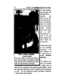
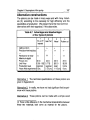
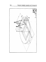
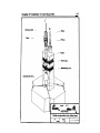
Although the current design was developed in the OAR—Region
V, it is a second generation design and has supposedly overcome some of the deficiencies of the earlier models (like the Pochote model), we still don’t have enough long—term experience,
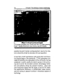
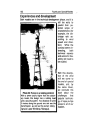
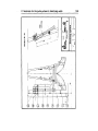
and therefore prefer not to present the detailed plans in this
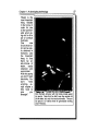
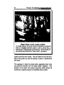
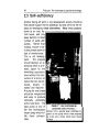
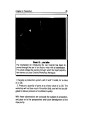
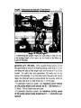
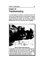
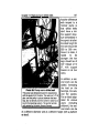
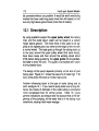
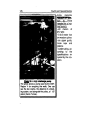
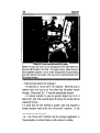
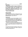
book: we limit ourselves to showing the photo.
11.2 Installation
The design of the pump (and therefore, the installation) depends mainly on how the the drilled well is built: the material
used, the diameter and height of the well’s lining tube, the dimensions of the base (if it has one), etc.
As with pumps for hand—dug wells, this installation also requires
two half days: one to embed the support structure and the other
for the actual installation.
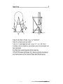
Embedding the pump
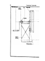
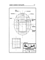
In general, the pump’s support structure is embedded in the
apron. The positioning should be such that the raising main is
exactly plumb underneath the pulley wheel. The base for the
outlet spout should be placed at a height so that it is easy to put
on and take off the bucket. Its section is 150 x 150 mm. minimum, with a reinforcement of four rods. Embed the outlet
spout. If the height of the spout allows, it’s wise to make a platform for the users to put their buckets on, leaving some 500
mm. between the spout and the platform. When you coat the
apron with cement, take into account the space needed by the
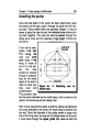
two users. At the same time, pour the triangular stabilizing rock
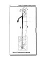
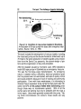
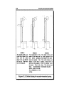
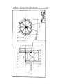
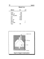
(see figure 11.1).
“