1
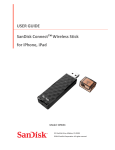
®
XD-V55 Digital Wireless
Pilot’s Handbook
Manuel de pilotage
Pilotenhandbuch
Pilotenhandboek
Manual del Piloto
取扱説明書
40-00-0339
also available @ www.line6.com/manuals
Rev B
Important Safety Instructions
C A UT I O N
RISK OF ELECTRIC
SHOCK DO NOT OPEN
WARNING : TO REDUCE THE RISK OF FIRE OR ELECTRIC SHOCK, DO NOT REMOVE SCREWS.
NO USER-SERVICEABLE PARTS INSIDE. REFER SERVICING TO QUALIFIED SERVICE PERSONNEL.
WARNING : TO REDUCE THE RISK OF FIRE OR ELECTRIC SHOCK, DO NOT EXPOSE THE
APPLIANCE TO RAIN OR MOISTURE.
CERTIFICATION
THIS DEVICE COMPLIES WITH PART 15 OF THE FCC RULES. OPERATION IS SUBJECT TO THE
FOLLOWING TWO CONDITIONS: (1) THIS DEVICE MAY NOT CAUSE HARMFUL INTERFERENCE,
AND (2) THIS DEVICE MUST ACCEPT ANY INTERFERENCE RECEIVED, INCLUDING INTERFERENCE THAT MAY CAUSE UNDESIRED OPERATION.
Warning: Changes or modifications not expressly approved in writing by Line 6 may void the users authority to
operate this equipment.
RF Exposure Statement: This transmitter must not be co-located or operated in conjunction with any other
antenna or transmitter.
Note: This equipment has been tested and found to comply with the limits for a Class B digital device, pursuant
to part 15 of the FCC Rules. These limits are designed to provide reasonable protection against harmful interference in a residential installation. This equipment generates, uses and can radiate radio frequency energy and, if
not installed and used in accordance with the instructions, may cause harmful interference to radio communications. However, there is no guarantee that interference will not occur in a particular installation. If this equipment
does cause harmful interference to radio or television reception, which can be determined by turning the equipment off and on, the user is encouraged to try to correct the interference by one or more of the following measures:
- Reorient or relocate the receiving antenna.
- Increase the separation between the equipment and receiver.
- Connect the equipment into an outlet on a circuit different from that to which the receiver is connected.
- Consult the dealer or an experienced radio/TV technician for help.
This Class B digital apparatus complies with Canadian ICES-003. This Category II radio communication device complies with Industry Canada Standard RSS-310. Cet appareil numerique de la classe B est conforme a la
norme NMB-003 du Canada. Ce dispositif de radiocommunication de catégorie II respecte la norme CNR-310
d’Industrie Canada
The FCC compliance sticker is attached to the THH12 battery compartment.
Remove the THH12 base by unscrewing counter clockwise to see this compliance sticker.
You should read these Important Safety Instructions.
Keep these instructions in a safe place
Before using your XD-V55 Digital Wireless System, carefully read the applicable items of these operating
instructions and the safety suggestions.
1. Obey all warnings in the XD-V55 manual.
2. Do not perform service operations beyond those described in the XD-V55 Manual. Service is required when
the apparatus has been damaged in any way, such as:
• liquid has been spilled or objects have fallen into the apparatus
• the unit has been exposed to rain or moisture
• the unit does not operate normally or changes in performance in a significant way
• the unit is dropped or the enclosure is damaged
3. Do not place near heat sources, such as radiators, heat registers, or appliances which produce heat.
4. Guard against objects or liquids entering the device. Do not use or place unit near water.
5. Do not step on cords. Do not place items on top of cords so that they are pinched or leaned on. Pay particular attention to the cord at the plug end and the point where it connects to the device.
6. Clean only with a damp cloth.
7. Only use attachments/accessories specified by the manufacturer.
8. Prolonged listening at high volume levels may cause irreparable hearing loss and/or damage. Always be sure
to practice “safe listening.”
TA-2009/1484
APPROVED
N222
20545/SDPPI/2011
3794
20543/SDPPI/2011
3794
(01)07899153000059
(01)07899153010271
Thank you for your purchase of the XD-V55 wireless microphone system. It is a sophisticated digital
wireless system, yet is easy to configure and use within minutes. With its fully digital transmission,
the system provides features and benefits that differ in some ways from previous generations of analog
wireless, but in most respects you use it just like other wireless systems. By understanding a few simple
concepts, you’ll be able to achieve superior audio quality, a secure and dropout-free signal, and the
ability to use multiple channels of wireless together without interference or other conflicts.
•Digital transmission in the 2.4 GHz band – license-free operation worldwide avoids
interference from high-power TV transmitters in the UHF band.
•24 bit digital technology provides the audio response of a cable, without companding.
•Up to 117 dBA dynamic range, and 10 Hz – 20 kHz bandwidth
•4th-generation technology promotes reliable, dropout-free performance
•Fast setup: without the need for gain, squelch or pilot adjustment
•12 channels supporting up to 12 simultaneous systems
•300 foot (100 meter) range
•Microphone modeling of popular vocal mics
•Bodypack EQ modeling for headset, instrument, and lavalier mics
•Accurate battery-life indicators on both transmitter and receiver
•Real-time LED ladders display critical performance parameters, including RF level, audio
level, and transmitter battery level
•Setup menus on transmitters provide additional parameter adjustments
Recommendations
for
Best Performance
•Maintain a clear line of sight between the transmitter and receiver antennas. Typically the
receiver antennas should be above head level. Avoid placing the receiver in the bottom of a
rack or cabinet unless remote antennas are employed.
•Avoid placing the receiver behind walls. When this is necessary the receiver’s antennas should
be remotely located as to be in sight of the transmitter.
•Avoid placing the receiver in close proximity to RF generating equipment including computers,
wireless access points and microwave ovens.
•Point the antennas up and 45 degrees from vertical while avoiding touching metal objects like
rack or rack rails.
•Avoid blocking antennas in the transmitters. Do not “cup” the bottom of the handheld
transmitter. Avoid placing the Bodypack transmitter in pockets.
4
Supplied Components
XD-V55 Receiver: : receiver, 9V / 0.5A external universal power supply, two (2) half-wave articulating
antennas, user’s manual
THH12 Handheld microphone Transmitter: two (2) AA alkaline batteries; mic stand clip. Optional
carry case.
or
TBP12 Bodypack Transmitter: two (2) AA alkaline batteries; optional lavalier mic with windscreen
and clip or headset mic with windscreen. Optional carry case
Available Accessories include: carry case, XD-AD8 antenna distribution system and remote antennas.
The XD-V55 digital wireless is available in the following system configurations:
XD-V55 Handheld Microphone System
XD-V55L Lavalier Microphone Bodypack System
XD-V55HS Headset Microphone Bodypack System
XD-55 Rack Mount Kit
Individual transmitters and receivers are available separately as well.
5
XD-V55 Digital Wireless Quick Setup
Receiver
1
2
3
MAIN OUTS
UNBAL
AUDIO
BATTERY
BALANCED
9VDC IN
CHANNEL
RF
5
6 7
9
10
2
11
12
1
MUTE
8
4
3
TRANSMITTER
STATUS
4
5
6
7
1. Antenna A & B Input Connectors (BNC)
2. Unbalanced 1/4-Inch and Balanced XLR Audio Output Connectors
3. 9VDC Power Input Connector
4. Transmitter Status LED Displays
AUDIO – lights green to indicate audio signal level, top clip LED lights red to indicate the audio
is clipping
MUTE – lights red when transmitter is muted
BATTERY – lights green, with all lit indicating full transmitter battery; bottom LED turns red
when 1 hour remains, and flashes red when less than 40 minutes remains
RF – lights green to indicate transmitter signal strength/quality; with transmitter off, red lights
indicate interference on that channel
5. Channel Select Encoder – selects channels 1 through 12
6. Dynamic Filter Button – engages dynamic filter to reduce stage and handling noise
7. Receiver Power Switch
Plug the power supply cable into the receiver and AC power. Connect and position the antennas.
Connect with an audio cable to a mixer or similar. Turn on the receiver power switch. Turn the Channel
Select Encoder to select a channel. Press the Dynamic Filter Button if desired. The receiver is ready
to use
6
Beltpack Transmitter
6
3
MUTE
AUDIO
1
OFF/ON
AUDIO
Pat. Pending
Made in China
Designed in U.S.A.
7
008WWA090153
8
FCC ID: UOB916TBP12
IC: 6768A-916TBP12
N222
BATT
BATT
4
5
2
1. ON / OFF Switch
2. Mini-XLR (TA4) Input Connector
3. MUTE Switch
4.SELECT
5.VALUE
6. Battery & Audio Status LEDs – Battery LED is blue when good, red when low, flashing when very
low; Audio LED is green for audio signal and red for clipping.
7. LCD Display Panel – Backlight will light briefly when transmitter is turned on and when changing
pages; will stay lit when muted; display also functions as programming window.
8. Belt Clip – Can remove the center mounting screw to reposition or remove, as necessary.
Open the battery door on the side of the beltpack and insert two AA batteries. Slide the ON/OFF
switch to turn on. Press and hold the SELECT button for two seconds, and CH and a flashing channel
number will appear on the LCD screen. Press the VALUE button repeatedly in order to change the
channel number to match the receiver. Press and hold the SELECT button for two seconds to select and
return to the main screen. The transmitter is ready to use.
7
MUTE
SELECT
Handheld Transmitter
1. Power / Mute Button – Press briefly to turn on; press and hold for two seconds to turn off. Press
and hold for one second to mute; press briefly to unmute. When in Setup Mode, press this button
to change the value of the parameter one step at a time.
2. Select Button – Press and hold for two seconds to enter Setup Mode; press briefly to go to next
setup page; hold two seconds to exit setup and save changes.
3. LCD Display Panel – Backlight will light briefly when transmitter is turned on and when changing
pages; will stay lit when muted; display also functions as programming window.
Unscrew the transmitter base and insert two AA batteries. Push the On/MUTE button to turn on. Press
and hold the SELECT button for two seconds, and CH and a flashing channel number will appear on
the LCD screen. Press the On/MUTE button repeatedly in order to change the channel number to
match the receiver. Press and hold the SELECT button for two seconds to select and return to the main
screen. The transmitter is ready to use.
What Makes
a
Wireless Digital?
In a typical analog wireless microphone system the signal between the transmitter and the receiver
consists of a very high frequency radio wave carrier that is continually varied slightly in frequency by
the audio signal from the microphone (or other transducer). The electronic circuitry in the receiver
removes the carrier frequency and leaves the audio signal – the same principle that is used in FM radio
broadcasts. The signal is highly compressed upon transmission and expanded at the receiver – the origin
of the word “companding.” Analog transmissions are vulnerable to many interference effects from other
RF and electromagnetic signals – and the interference is usually audible as well as having the effect of
shortening range or rendering the channel unusable.
Input
Signal
(dBu)
+ 25
+ 20
+ 15
+ 10
+ 5
0
- 5
- 10
- 15
- 20
- 25
- 30
- 35
- 40
- 45
- 50
- 55
- 60
- 65
- 70
- 75
- 80
- 85
- 90
2:1 Compression Ratio
100dB
Dynamic
Range
50dB
Dynamic
Range
Output
Signal
(dBu)
+ 25
+ 20
+ 15
+ 10
+ 5
0
- 5
- 10
- 15
- 20
- 25
- 30
- 35
- 40
- 45
- 50
- 55
- 60
- 65
- 70
- 75
- 80
- 85
- 90
Input
Signal
(dBu)
+ 25
+ 20
+ 15
+ 10
+ 5
0
- 5
- 10
- 15
- 20
- 25
- 30
- 35
- 40
- 45
- 50
- 55
- 60
- 65
- 70
- 75
- 80
- 85
- 90
No Compression
117dB
Dynamic
Range
117dB
Dynamic
Range
Output
Signal
(dBu)
+ 25
+ 20
+ 15
+ 10
+ 5
0
- 5
- 10
- 15
- 20
- 25
- 30
- 35
- 40
- 45
- 50
- 55
- 60
- 65
- 70
- 75
- 80
- 85
- 90
Digital wireless microphone systems provide a much more robust and interference resistant performance.
Within the microphone transmitter, the audio signal from the voice or other source is digitally sampled,
and the sample is converted into a digital “word” consisting of the electrical equivalent of a string of
1’s and 0’s. As in analog wireless, a very high frequency carrier wave is modulated, but in this case with
the digital “stream” of samples so that the carrier frequency only has two distinct states that represent
8
the signal in the same manner that the flat areas and pits on a CD represent the music. The receiver
retrieves this information from the carrier and decodes it via a D/A converter and outputs an audio
signal that is the replica of what was encoded at the mic.
Analog signal with noise
Digital signal with noise
Benefits of Digital Wireless
As mentioned above, analog wireless transmissions are susceptible to a variety of noise and interference
conditions, related to signal strength and/or interference from external electronic devices and other
wireless signals. These can ride along with the carrier frequency and its audio signal as added noise,
affect the receiver directly because the antennas that pick up the transmitter signal are also wide open
to pick up other radio signal in the same general RF band, or interact with the carrier frequency to create
additional harmonic frequencies. Problems can come from sources as diverse as a television broadcast
signal, other wireless mics in use, digital signal processors, or even malfunctioning fluorescent lighting
ballasts or other electrical devices.
While the same physics applies to a digital signal riding on a carrier wave, the digital signal with just two
states is more difficult to damage. If the receiver finds that something has come in that is not equivalent
to a digital word of 1’s and 0’s, that information will be ignored. If noise is riding on those digital words,
it is still decoded as one of two states – rather than something in-between, if it were analog. As long as
the digitally modulated carrier arrives at the receiver’s antenna with sufficient level, it will be accurately
decoded. And as with CD players and other digital audio devices, error concealment algorithms may be
added to fill in the gaps where there is missing information.
Typically with a digital wireless system, the signal will retain its quality until the signal level is too low,
and then it’s gone. The main effect that interference has on a digital wireless system is that it will shorten
the maximum range between the transmitter and receiver antenna. To alleviate potential problems,
maintain line-of-sight between transmitter and receiver, locate the receiver / receiver antennas at a
distance from interfering sources such as WiFi routers.
XD-V55 Receiver Detailed Setup
For stand-alone placement, position the receiver on a level surface where the front-panel controls and
displays are visible.
•Connect the supplied DC-1g power supply to the 9 VDC In connector on the rear panel.
•To secure, press a loop of the cable through the cable holder located above the connector to
prevent accidental disconnection.
•Plug the power supply into an available AC outlet that provides voltage from 90 – 240 VAC.
•Place the supplied half-wave antennas on the left and right BNC connectors marked Antenna
A and Antenna B. Rotate a quarter-turn clockwise, and then position the antennas at an
approximately 45 degree “rabbit ears” orientation.
•On the right side of the front panel, turn on the power switch; the LED will light.
•Turn the encoder to select the desired channel, from 1 to 12.
•To sync the handheld or Bodypack transmitter to the receiver, follow the procedure in the
following transmitter setup sections.
Note: The receiver’s RF channel will change immediately to a new frequency when the encoder is
turned.
9
Note: The Audio level meter has 4 lower green LEDs that correspond with specific audio input levels,
plus a red clip light in the top position. From bottom to top, LED 1 = -60 dB, 2 = -30 dB, 3 = -18 dB,
and 4 = -6 dB.]
THH12 Handheld Transmitter Detailed Setup
To begin, twist the bottom section of the THH12 transmitter counterclockwise, unscrew and remove
it. Lightly pull the battery cover tab down with a thumbnail, and open the cover by pulling back; it is
hinged at the base of the transmitter. Insert two AA batteries, noting the polarity markings shown in
the battery compartment.
Note, Use alkaline batteries, or rechargeable NiMH batteries in the 2400 – 2800 mAh range. See
Battery Level Indicator Functions, for more details.
AA BATTERY
Close the battery cover and replace the bottom section of the transmitter. Press and briefly hold the left
ON/MUTE button located below the display. The top line shows the currently selected channel, and the
bottom line shows remaining battery life. The backlight will light for a few seconds, and then turn off.
Note, The transmitter buttons are recessed to prevent accidental activation, so press them down firmly
below the recessed surface, until you feel a click. Avoid using pointy objects such as ball point pens.
The transmitter must be set to the same channel as the receiver it is to work with (if the receiver is on
channel 9, the transmitter must also be set to channel 9). Press and hold the SELECT button for two
seconds, and the display will show CH on the top line, and the currently selected channel on the second
line. Press the ON/MUTE button to go through channels 1 through 12, with each click incrementing
to the next channel; the channel number will flash. At the desired channel, stop and press and hold the
SELECT button for two seconds (or do not press any button for 15 seconds). The transmitter will then
change to the newly selected frequency, and return to the main display. Check the receiver display to
confirm that the transmitter signal is being received.
Note: The transmitter must be set to the same channel as the receiver it is to work with (if the receiver
is on channel 9, the transmitter must also be set to channel 9). Check the receiver’s RF and Audio LED
displays to confirm that the transmitter signal is being received.
When the transmitter is on, a quick push of the ON/MUTE button will mute the audio from the mic, and
the backlight will remain lit while it is muted. The word MUTE will appear on the display. Another
quick push will un-mute it. The THH12 transmitter has other editable functions, such as selectable
10
microphone models. For more details, see Setting Microphone Models.
Note: The transmitter can be locked so that the user cannot accidentally or deliberately make changes
to its settings during use. For more details, see Locking, Unlocking, and Muting the Transmitter.
TBP12 Beltpack Transmitter Detailed Setup
To begin, press the small oval battery lock button on the left side of the transmitter (same side as the
antenna and OFF/ON slide switch), and slide the rubberized rectangular latch up toward the switch.
The battery door will flip open. Insert two AA batteries, noting the polarity markings on the metal insert
on the inside of the door. Close the battery door and slide the battery latch to the original position.
Slide the OFF/ON switch to the On position; the display will show the currently selected channel and
remaining battery life.
Note, Use alkaline batteries, or rechargeable NiMH batteries in the 2400 – 2800 mAh range. See
Battery Level Indicator Functions, for more details.
The beltpack transmitter has a TA4M 4-conductor connector for lavalier, headset, and instrument
microphones. The microphone must have a TA4F connector to mate with the beltpack. Align this
connector until it slides easily into the beltpack, and press down until it is seated. To remove, press the
button on the side of the TA4F connector and pull straight out. For more on the application of lavalier
and headset mics, see Microphone Usage Tips.
The transmitter must be set to the same channel as the receiver it is to work with (if the receiver
is on channel 9, the transmitter must also be set to channel 9). Press and hold the SELECT button
for two seconds, and the display will show [CH] on the top line, and the currently selected channel
on the second line. Press the VALUE button to go through channels 1 through 12, with each click
incrementing to the next channel; the channel number will flash. At the desired channel, stop and
press and hold the SELECT button for two seconds (or do not press any button for 15 seconds). The
transmitter will then change to the newly selected frequency, and return to the main display. Check the
receiver display to confirm that the transmitter signal is being received.
Note: The transmitter must be set to the same channel as the receiver it is to work with (if the receiver
is on channel 9, the transmitter must also be set to channel 9). Check the receiver’s RF and Audio LED
11
displays to confirm that the transmitter signal is being received.
When the transmitter is on, a quick push and hold of the MUTE button will mute the audio, and the
backlight will remain lit while it is muted. The word [MUTE] will appear on the display. Another quick
push will un-mute it.
Connecting
the
XD-V55 Receiver
The receiver features a balanced XLR and unbalanced (tip-sleeve) quarter-inch connector. To connect
to a mixing board or powered mixer, use a microphone cable between the receiver output and the
mixer’s mic-level input – in the same way as you would connect a wired microphone. The output
of the XD-V55 receiver is virtually identical to that of the microphone on the transmitter (and the
microphone models on the THH12 handheld transmitter emulate the output levels of the particular
microphones they model).
To connect to an instrument amplifier or other audio equipment with a quarter-inch connector such as
a signal processor or effects unit, use a quarter-inch to quarter-inch instrument cable; this output is also
mic level. If desired to minimize stage rumble or handling noise, press the DYNAMIC FILTER button
on the receiver. Note: Do not use TRS or Stereo style connectors/cables with the ¼ inch connector as
the ring is used for data transmission in factory setup and may cause computer like noise to be coupled
into your audio.
Dynamic Filter
The dynamic filter allows users to select between off (no filtering) or on (for most music and spoken word
applications). When active, the filter minimizes handling noise and stage vibrations, via a downward
expander with a dynamic high-pass filter. To engage the filter, press the Dynamic Filter Button, which
will light when on. The dynamic filter becomes immediately active upon selection.
Setting Microphone Models
Selecting Mic Models with the THH12 Handheld Transmitter
The THH12 handheld microphone transmitter features selectable models of several popular vocal
microphones, including their audio quality, frequency response, and output level. The models include
the Shure® SM58®, Shure® SM57®, and Sennheiser® e835 – along with the custom Line 6 model.*
Note, The models begin with the response parameters of the Line 6 microphone element, and shape
it to attain the characteristics of other microphones. Some physical characteristics of these other
microphones, such as their off-axis response, polar pattern, and proximity effect are unable to be
duplicated with a single mic element.
To select a particular microphone model, press and hold the SELECT button until the display changes
to the channel setting screen. Quickly press the SELECT button two more times to go to the [MODEL]
page. You will see a two- or three-digit designation for the currently selected mic model; press the ON/
MUTE button to scroll through the available models – one per click. The model names will flash. To
select one of the models, press the SELECT button (the display goes to the next page of selection
options) or do not push any buttons for approximately 15 seconds.
12
Display
Manufacturer
L6
Line 6
Custom
Shure®
SM58
Shure®
SM57
Sennheiser®
e835
58
57
835
Model
Note, In a production using both wired and wireless microphones, the modeling allows the user to select
a wireless mic model that is similar to the majority of wired ones. This selection should help reduce
potential feedback from dissimilar microphone frequency responses when using global EQ settings on
the audio system.
*All product names herein are trademarks of their respective owners, which are in no way associated or affiliated with Line 6. These trademarks of
other manufacturers are used solely to identify the products of those manufacturers whose tones and sounds were studied during Line 6’s sound model
development. SHURE and SM58 are registered trademarks of Shure Incorporated. Sennheiser is a registered trademark of Sennheiser Electronic Corp.
Selecting Equalization Models with the TBP12 Beltpack Transmitter
The TBP12 beltpack transmitter may be used with a wide variety of lavalier, headset, and instrument
microphones, as well as with a quarter-inch instrument cable. Some of these microphones are available
from Line 6; with the correct wiring and a TA4F connector, virtually any mic may be used. To help
the user achieve the best performance from the microphones in a multitude of applications, sets of
equalization models are provided.
Note, See the TA4F wiring instructions in the Appendix at the end of the manual.
To select a particular equalization model for a lavalier, headset, or instrument microphone, press and
hold the SELECT button until the display changes to the channel setting screen. Quickly press the
SELECT button two more times to go to the [MODEL] page. You will see a three-digit designation for
the currently selected mic EQ model; press the VALUE button to scroll through the available models
– one per click. The model names will flash. To select one of the models, press the SELECT button
(the display goes to the next page of selection options) or do not push any buttons for approximately
15 seconds.
Name
Application
Description
FLAT
No Equalization
No roll off or boost to signal
S1
Microphone EQ
Vocal EQ setting 1 (low cut)
S2
Microphone EQ
Vocal EQ setting 2 (head worn lavalier setting)
IF
Instrument
20 foot guitar cable high frequency roll off
13
Microphone Usage Tips
Unlike a handheld microphone where the user typically speaks or sings directly into the mic element
– where the full frequency response of both the person and the mic is available, lavalier microphones
are placed on the body in a variety of places. Being farther away from and below or to the side of the
mouth, the level is usually much lower, plus the frequency response lacks the highs as well as the lows
from being near the mic element. The sound is often hollow and emphasizes the midrange. When you
increase the gain to bring back the level of the voice, other extraneous noises are also more easily picked
up and amplified.
The sometimes substantial equalization corrections necessary to make the voice of the lavalier user
sound “natural” can be quite difficult to achieve without feedback problems, especially with live audio
at higher levels. Using a combination of mic placement and EQ is the best compromise for good sound
at usable levels – and the transmitter’s EQ response models will help the process.
Try to maintain a constant distance and relationship between the user’s mouth and the microphone. In
live theatre this is often done by placing a small mic in the hairline toward the front side of the head or
right above the ear. With mic placement on the collar or shoulder area, changes in level can occur as the
user’s head turns; experiment with the location of the mic to minimize this effect. Mic placement in the
center of the chest can help with the level changes, but is farther from the voice and quite shielded from
the direct energy of the voice, so typically provides a hollow midrange or “chest” sound to the voice.
Directional (cardioid) lavalier microphones can help isolate the voice of the user from the background
noise that may be picked up by an omnidirectional mic. They are more sensitive to the movements of
the user’s head, with more change in level when speaking toward or away from the front of the mic. In
addition, they are more prone than omni mics to handling and cable noise, so the user needs to be more
careful about movement. The lavalier EQ models in the TBP12 beltpack provide a high-pass filter (lowend rolloff) to help reduce this extraneous noise.
When appropriate, a headset microphone can solve most of these problems of level, compromised
frequency response, feedback potential, handling noise, and pickup of background sounds. A number of
low-profile models are available. To minimize breath noise and pops from certain consonants, use the
mic’s wind filter and position the mic element toward the corner of the mouth.
In a situation where the audio is recorded or broadcast rather than live, or the user has a significant
distance between his/her location and the speaker system, substantial equalization changes and a more
natural sound are easier to achieve.
Setting Other Transmitter Functions
Locking, Unlocking, and Muting the Transmitter
MUTE
SELECT
The THH12 and TBP12 transmitters can be locked to prevent accidental button pushes from handling
during use. When locked, the user cannot mute or turn off the transmitter, or change the frequency or
other settings, assuring that an error with a transmitter will not interrupt the event. After use, it is easy
to unlock the transmitter to turn off or change settings. When not locked, the transmitter can be muted
so that it keeps transmitting but audio is temporarily disabled.
BATT
MUTE
AUDIO
OFF/ON
To mute the THH12 handheld, quickly press the ON/MUTE button until it clicks; press again to
unmute. The word [MUTED] will appear in place of the transmitter name, and the backlight will stay
lit. To mute the TBP12 beltpack, push and briefly hold the MUTE button on the top of the pack; press
again to unmute. The display works identically to the handheld. When the mic is muted and you press
14
the SELECT button to enter another parameter page, the word [MUTED] will remain in tiny characters
in the left center of the display as a reminder. When a transmitter is [MUTED] the red MUTE LED will
light on the receiver.
To lock the THH12 handheld, turn it on and assure that the desired settings are completed, and that the
receiver display shows the signal. Unscrew the end of the battery compartment, and locate the microswitch on the back; move it to the right toward the lock symbol. Test by pressing the ON/MUTE or
SETUP buttons, and the word [LOCKED] will appear on the top line of the briefly lit display. Unscrew
the compartment and move the switch to the left to unlock.
To lock the TBP12 beltpack, turn it on and check the settings, and check the receiver display for signal.
With two fingers, press the SELECT and VALUE buttons at the same time and hold for two seconds.
The word [LOCKED] will appear on the top line of the display for a moment, and then revert to the
main screen. Test by pressing any of the buttons to assure that it is locked. Locking will also temporarily
disable the OFF/ON switch. To unlock, again hold the SELECT and VALUE buttons for two seconds.
Press together and hold
Battery Level Indicator Functions
Line 6 transmitters contain battery level indicators that can accurately assess the remaining battery life,
and show this information on both the transmitter and the associated receiver. These indicators are
calibrated to commercial alkaline batteries, and can also provide useful information when used with
rechargeable batteries.
When the transmitter is turned on, the bottom line of the display will show the remaining battery
life in hours and minutes, with a battery icon next to the time. The remaining battery life is shown in
increments of twenty minutes (Hours:20). The initial time indicated just after the transmitter is turned
on, and for the first few minutes, will often show more time than is actually remaining – this is due to
the characteristic of alkaline batteries to temporarily increase in voltage for a short time after a period of
rest. For best accuracy, wait about twenty minutes after transmitter turn-on to rely on the time indicator.
AUDIO
BATTERY
MUTE
TRANSMITTER
STATUS
RF
15
On the receiver, the remaining battery life will be shown on the middle 5-position LED ladder, which
indicates remaining battery life in one-hour steps. When remaining battery life is more than five hours,
all five LEDs are lit, with between four and five hours left, four LEDs are lit, and so on. When less than
one hour of battery life remains, the bottom LED will turn from green to red – and will begin to flash in
the last 40 minutes of life.
NiMH (nickel metal hydride) batteries in the 2400 – 2800 mAh range are recommended as rechargeable
batteries to use with the THH12 and TBP12 transmitters. Make sure that the batteries fit properly in
the battery compartments to prevent damage, since these batteries can vary in diameter and length.
They need to be charged in the correct external battery charger; the transmitters are not designed for
batteries to be charged internally. Because the transmitter’s battery meter was calibrated for alkaline
batteries, they will not be as accurate in calculating the remaining battery life when using rechargeable
batteries
Note, Carbon-zinc batteries are not recommended.
Range
and
Interference Testing
The XD-V55 receiver’s RF LED ladder provides a useful tool for selecting the clearest channels, avoiding
interference, and preventing the wireless microphone systems from interfering with other wireless
devices. Using this function before operating the systems in new locations will promote trouble-free
and compatible performance.Scanning the Channels for Interference
AUDIO
BATTERY
MUTE
TRANSMITTER
STATUS
RF
Detecting Interference with the RF Meter
The XD-V55 receiver has an LED ladder (stacked LED meter) labeled RF, which detects signals on the
channel frequencies to which it is currently set (for example, when set to Line 6 channel 7, it detects
frequencies with either a 2.433 GHz or 2.467 GHz center frequency). These LED’s are green when
receiving signal from a Line 6 transmitter, and red when the transmitter is off and interfering signals on
that frequency are present. If the receiver is on and the associated transmitter is off, and one or more
of the LEDs on the RF meter are lit red, it is detecting a potentially interfering signal. The more LEDs
that are lit, the stronger the signal – and the more it will interfere with the range and performance of a
transmitter on that channel.
Note: When the associated handheld or Bodypack is on, these same bars show the transmitter’s signal
strength at the receiver’s antennas. During normal operation, you should see four green bars – and as
you begin to exceed the range you will see fewer bars. At three bars the signal will still be good, and at
two it should still be acceptable and provide reliable audio.
Walk-Testing the Performance Area
When first setting up a wireless system in a new location, it is good practice to position the receiver and
its antennas where they will remain during the event, and then walk the entire performing area with
the audio system on and the transmitter active. Talk and listen for signal dropouts or other problems,
and note where they are with respect to your antenna placement.
If you for some reason cannot turn on the audio system, with one person to walk with the transmitter
and another to monitor the receiver, you can use the RF LED meter to find locations with low signal
16
strength that could potentially cause problems. You can also monitor the signal through a headset
connected to the mixer, if the receiver has been connected to it.
If you are using remote antennas (with the XD-DA8 antenna distribution system), you can reposition
them to obtain better coverage and improve or eliminate areas with lower signal strength. With the
antennas connected to the receiver, you can place it where it has better line-of-sight to the transmitter.
Note: If there are still spots where poor signal reception occurs, mark the problem areas on the floor
with removable tape and let the user know to avoid those areas.
Avoiding WiFi Interference
If you see moderate to strong interference on one or more channels as shown by the RF LEDs turning
red when the transmitter is off, it is likely that you are seeing a WiFi channel that is operating in the
same location. If you can locate that equipment and position your receivers farther from it, or remote
the receiver antennas farther from it if using an antenna distribution system, the interference may lessen
in strength. Also be aware that your transmitters may interfere with the WiFi network operation if they
are transmitting close to the routers. The best option when you see strong interfering signals is to use
the other available Line 6 channels that are clear.
The most commonly used WiFi channels (note that their numbering does not correspond with Line
6 channels) are channels 1, 6, and 11. These channels each cover 20 MHz of spectrum, and usually
only one WiFi channel will be in use in a location. In the majority of cases, any of the Line 6 wireless
channels will be compatible with existing WiFi with minimal to no interference, and in all cases you
will be able to use six to eight channels of Line 6 wireless while completely avoiding the WiFi channel.
Use the channels in the following chart.
Channel
Frequency A
Frequency B
Compatibility
1
2425
2475
Compatible with WiFi 1, 6, & 11
2
2422
2472
Compatible with WiFi 1, 6, & 11
3
2402
2450
Compatible with WiFi 1, 6, & 11
4
2447
2478
Compatible with WiFi 1, 6, & 11
5
2428
2453
Compatible with WiFi 1, 6, & 11
6
2430
2461
Compatible with WiFi 1
Compatible with WiFi 1
7
2433
2467
8
2436
2469
Compatible with WiFi 1
9
2413
2456
Compatible with WiFi 6
10
2416
2458
Compatible with WiFi 6
11
2407
2464
Compatible with WiFi 6
12
2405
2439
Compatible with WiFi 11
Note: Cellular phones with Bluetooth or WiFi capabilities transmit signals in the 2.4 GHz band, so are
a potential source of interference when near the receiver antennas. Use these functions of your phone
at least a few feet away from the receivers when you are operating the wireless system.
17
Minimizing Near / Far Transmitter Effects
Line 6 digital wireless systems are designed so that a receiver only passes audio from a transmitter that
is set to the same channel. While other nearby transmitters and RF sources will not create audio in a
receiver not on their channel, under certain conditions they can have an effect on range. When you are
using several channels of wireless, following some simple procedures will minimize any near / far effects.
The XD-V55 receiver constantly monitors the signal from its transmitter, and increases gain (sensitivity)
as the transmitter moves farther away to maintain a good RF signal level. The near / far effect can
happen when the transmitter is at a distance from the receiver’s antennas, and transmitters on different
channels are being used near the antennas. The strong signal from the nearby transmitters, especially
if they are close in frequency to the channel the receiver is set on, can mask the signal from the distant
transmitter – and sometimes cause the audio from that transmitter to drop out.
For example, if the transmitter on the same channel as the receiver is 50 feet away, and another
transmitter is 3 feet from the receiver’s antenna, the range of that distant transmitter might be affected.
Avoid this potential problem by positioning the receivers and their antennas at a more equal distance
from the transmitters that are in use.
Solutions include:
•Making sure that any transmitter is at least 6 feet away from the receivers, and that other RF
sources (such as WiFi routers) are also at a distance from them.
•Placing the antennas higher, which can lessen the difference in distance as well as increase
line-of-sight with the distant transmitter.
•Using remote antennas (with the XD-AD8 antenna distribution system) and placing them
approximately equidistant from each group of transmitters (for example, positioning a remote
antenna connected to Antenna A nearer to the closer transmitters, and one connected to
Antenna B nearer to the distant transmitters).
•Moving the receiver associated with the distant transmitter closer to it.
Antenna Mounting
and
Placement
The XD-V55 receiver is typically used stand-alone, though two will fit side-by-side on a rack tray. When
used by itself and placed on a surface, the antennas are mounted on the rear and connected to the BNC
connectors labeled Antenna A A and Antenna B . Multiple receivers can share one pair of antennas by
using the XD-AD8 antenna distribution system and P180 directional or P360 omnidirectional remote
antennas.
Note: When rack-mounting receivers, it is preferable to keep them – and their associated antennas –
toward the top of the rack so that line-of-sight to the transmitters is unobstructed for the best range and
performance. Also, keep receivers and equipment such as digital signal processors, computers, WiFi
wireless routers, and other devices that emit RF energy as separated from each other as possible.
Remote antennas become important especially when the distance is significant between the transmitters
and receivers, there are walls or other obstacles between them, or when the receivers are “permanently”
mounted in an equipment room or production vehicle and the transmitters are used at various and
changing locations and distances.
To connect remote antennas to receivers via the XD-AD8, use low-loss 50-ohm coaxial cable with the
appropriate BNC connector on each end. Place the antennas with clear line-of sight to the location
where the transmitters will be used; the Line 6 active antennas provide the convenience of mic stand
mounting. Attach one end of the cable to the antenna, and run it the shortest possible distance to the
antenna distribution system, and from there to the Antenna A / Antenna B connectors on the back of
the receiver.
18
Note: As the RF signal travels through the cable to the receiver, there will be some loss of signal level,
which at greater lengths and with higher loss cables can be significant. With a passive antenna, use the
lowest loss cable you can find and try not to exceed about 15 feet of length. With an active antenna that
provides additional gain, set it to the proper amplification for the cable length, and try not to exceed
100 feet of cable.
When used properly, remote antennas can increase range and lessen dropouts and interference
conditions, compared with having the half-wave antennas directly connected to the receiver. This is
especially true when the receivers must be located in a non-line-of-sight position or behind obstacles.
Omnidirectional antennas are best applied when the users will be transmitting from a wider area – in
front, to the sides, and even behind the antenna. Directional antennas provide greater signal strength
at the front of the antenna, and greater rejection of the signal at the rear – in the case of the P180,
a cardioid coverage pattern of approximately 90 degrees with a rolloff to the sides. Use them when
the users are in a more confined area or not roaming as much. They can also be used to minimize an
interfering signal source by facing the back of the antenna toward the interferer and the front toward
the transmitters.
19
APPENDICES
Troubleshooting
Problem
Solution
No Audio
Switch on transmitter and/or receiver
Change transmitter batteries
Confirm proper polarity of batteries in transmitter
Transmitter audio muted; press MUTE button to unmute
Transmitter and receiver are on different channels; set to same channel
Receiver not connected to audio system, or audio system off or muted
Transmitter Stays On
Transmitter locked; unlock and then turn off
Shorter Range
Antennas not connected to receiver; check connections
Receiver antennas not in line-of sight; raise them or clear obstructions
Interference from other source; change channel and see Near / Far in manual
Place receiver / receiver antennas farther from WiFi or other 2.4 GHz source
Signal Dropouts
Too great a distance between transmitter and receiver; move them closer
Remote the antennas closer to transmitter (with XD-AD8 antenna distribution)
Keep receiver / antennas higher in line-of-sight; no doors or walls obstructing
Changing Transmitters from RF2 (default XD-V55) Mode to RF1 Mode
THH12 handheld and TBP12 Bodypack transmitters operate in a two-frequency mode, where the digital
audio signal is encoded onto two RF carriers at different center frequencies; this provides redundancy
and reliability even when interfering signals are present. The older Line 6 digital wireless systems, such
as the XD-V70, used a four-frequency transmission mode. When using the newer V55 transmitter
with a V70 receiver, it is necessary to change the transmission mode to the earlier method, using the
following procedure.
THH12 Handheld or TBP12 Bodypack
•With the transmitter on, hold the Select button until the channel number flashes.
•Press and hold the On/Mute (power) button and then quickly press the Select and Value (or
Select and Power for Hand Held); press within one second, as waiting longer may turn off the
transmitter.
•Note that the top line of the LCD display changes temporarily to [RF-1] in place of [CH],
indicating that the transmitter is now in a transmission mode that is compatible with XD-V70
and XD-V30 receivers.
•To return to the RF2 transmission mode, repeat the above process of pressing the power button
quickly followed by the Select button from the [CH] page. The top line of the display will
temporarily show [RF-2] to indicate the mode change.
•Note that the transmission mode that is set in this manner will be remembered when the
transmitter is powered off.
20
XD-V55 Digital Wireless System Specifications
System
Frequency Band
2.4GHz ISM Band
Compatible Channels
12
Spatial Diversity with Digital Buffering
Yes
Frequency Diversity
Yes (2 Frequencies per channel)
Compander-Free Design
Yes
Frequency Response THD %
10 Hz (-0.5 dB) - 20kHz (-2.5 dB)
0.03% typical
System Latency
< 2.9 ms (audio input to output)
Operating Temp Range
0 – 50 degrees C
Construction
XD-V55 Receiver
THH12 & TBP12 Transmitters
Extruded aluminum chassis
Metal enclosures
Receiver
RF Performance Monitoring
Yes (via LCD screen and LED)
RF Signal Strength Indicators
5-Segment LED
Audio Level Meter (on Receiver)
5-Segment LED
Dynamic Filter
Yes
Squelch & Pad adjustments
None required
Number of Receiver Antennas
2
Receiver Format
1/2 RU (with included rack-mount kit)
Receiver Power Requirements
9Vdc 500mA
Output Impedance
XLR: 150 Ohms Balanced
1/4”: 1 kOhm Unbalanced
Sensitivity
-95 dBm
Image Rejection
56 dB
Antenna Distribution
A and B
Antenna Impedance
50 Ohms
21
Transmitters
Transmitter RF Output Power
10 mW
Battery Life
8 hours
Mic Modeling
THH12 Handheld
TBP12 Beltpack
Yes (4 selectable models)
Yes (3 selectable EQ filters)
Batteries
2 x AA Alkaline
Battery Display (on Transmitter)
LCD Screen
Dynamic Range
THH12 Handheld
TBP12 Beltpack
>113 dB
>117 dB
TBP12 Maximum Audio Input Level
6.5 Vpp
TBP12 Beltpack Input Impedance
1.3 M Ohms
TBP12 Beltpack Supplied Bias Voltage
5 VDC (on Pin 2 of TA4F Connector)
Transmitter Audio Polarity
Positive pressure on mic diaphragm produces
positive voltage
Pinout To TA4F Connector
•1 = Ground
•2 = Positive Voltage
•3 = Signal
22