1
NOR
MAL
BATT
ERY
BYPA
SS
FAUL
T
ES
C
ON
OF
F
The power behind competitiveness
Delta UPS - Ultron Family
HPH Series, Three Phase
20/30/40 kVA
User Manual
www.deltapowersolutions.com
Save This Manual
This manual contains important instructions and warnings that you should follow
during the installation, operation, storage and maintenance of this product. Failure
to heed these instructions and warnings will void the warranty.
Copyright © 2014 by Delta Electronics Inc. All Rights Reserved. All rights of this User Manual
(“Manual”), including but not limited to the contents, information, and figures are solely owned and
reserved by Delta Electronics Inc. (“Delta”). The Manual can only be applied to the operation or the
extraction, or usage of this Manual in whole or in part is prohibited without the prior written permission
of Delta. Given that Delta will continuously improve and develop the product, changes may be made
to the information in this Manual at any time without obligation to notify any person of such revision
or changes. Delta will make all possible efforts to secure the accuracy and the integrity of this
Manual. Delta disclaims any kinds or forms of warranty, guarantee, or undertaking, either expressly
or implicitly, including but not limited to the completeness, faultlessness, accuracy, non-infringement,
Ultron HPH Series UPS
ii
Table of Contents
Table of Contents
Chapter 1 : Important Safety Instructions ------------------------------------------ 1
1.1
Placement Warnings ----------------------------------------------------------------- 1
1.2
Connection Warnings ---------------------------------------------------------------- 1
1.3
Usage Warnings ---------------------------------------------------------------------- 1
1.4
Storage Warnings --------------------------------------------------------------------- 2
1.5
Glossary of Symbols ----------------------------------------------------------------- 3
1.6
Standard Compliance ---------------------------------------------------------------- 4
Chapter 2 : Introduction ------------------------------------------------------------------ 5
2.1
Product Introduction ------------------------------------------------------------------ 5
2.2
Package Inspection ------------------------------------------------------------------ 5
2.3
Functions and Features ------------------------------------------------------------ 6
Chapter 3 : Appearance and Mechanism-------------------------------------------- 8
3.1
Appearance and Dimensions ------------------------------------------------------ 8
3.2
Front Panel ----------------------------------------------------------------------------- 8
3.3
Rear Panel---------------------------------------------------------------------------- 10
Chapter 4 : Operation Modes ----------------------------------------------------------13
Chapter 5 : Communication Interfaces ---------------------------------------------17
Chapter 6 : Installation and Wiring ---------------------------------------------------24
6.1
Precautions Prior to Installation and Wiring ---------------------------------- 24
6.2
Installation Environment----------------------------------------------------------- 24
6.3
UPS Transportation & Handling ------------------------------------------------- 25
6.4
UPS Installation --------------------------------------------------------------------- 25
6.5
Wiring ---------------------------------------------------------------------------------- 27
6.5.1
Precautions Prior to Wiring --------------------------------------------- 27
!"
-------------------------------- 30
6.6
6.5.3
Single Unit Wiring--------------------------------------------------------- 32
6.5.4
Parallel Units Wiring ----------------------------------------------------- 38
External Battery Cabinet Connection Precautions ------------------------- 40
iii
Chapter 7 : Operation ---------------------------------------------------------------------44
7.1
Connecting the UPS with the Utility AC Power ------------------------------ 44
7.2
Turn-on -------------------------------------------------------------------------------- 44
7.3
Turn-off -------------------------------------------------------------------------------- 44
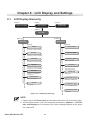
Chapter 8 : LCD Display and Settings ----------------------------------------------46
8.1
LCD Display Hierarchy ------------------------------------------------------------ 46
8.2
Main Screen -------------------------------------------------------------------------- 47
8.3
Parallel Screen ---------------------------------------------------------------------- 48
8.4
Main Menu ---------------------------------------------------------------------------- 49
8.5
Measure ------------------------------------------------------------------------------- 50
8.6
Maintenance ------------------------------------------------------------------------- 51
Chapter 9 : Optional Accessories ----------------------------------------------------54
Chapter 10 : Maintenance ---------------------------------------------------------------55
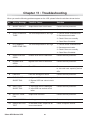
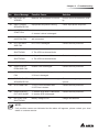
Chapter 11 : Troubleshooting ----------------------------------------------------------56
----------------------------------------------58
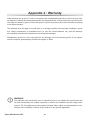
Appendix 2 : Warranty --------------------------------------------------------------------60
Ultron HPH Series UPS
iv
Chapter 1
Important Safety Instructions
Chapter 1 : Important Safety Instructions
1.1
Placement Warnings
y
y
1.2
Leave adequate space around all sides of the UPS for proper ventilation. Please refer to 6.2
Installation Environment.
Connection Warnings
y
y
y
1.3
Install the UPS in a well-ventilated indoor area, away from excess moisture, heat, dust,
#$
%
The UPS must be well grounded due to a possible risk of current leakage.
It is necessary to install protective devices and 4-pole contactors when the UPS is connected to the mains and bypass source. For relevant information, please refer to 6.5.1
Precautions Prior to Wiring.
The protective devices connecting to the UPS must be installed near the UPS and must be
easily accessible for operation.
Usage Warnings
y
y
y
This is a class-A product. In a domestic environment, this product may cause radio interference, in which case, the user is required to take adequate measures.
The UPS can be used to power computers and associated peripheral devices, such as
monitors, modems, cartridge tape drives, external hard drives, etc.
'*
+
vice personnel.
y
It is strictly forbidden to connect the UPS with any regenerative-type loads.
y
The parallel UPSs can connect with common batteries.
y
y
y
The external slits and openings in the UPS are provided for ventilation. To ensure reliable
operation of the UPS and to protect the UPS from overheating, these slits and openings
must not be blocked or covered. Do not insert any object into the slits and openings that
may hinder ventilation.
In a low temperature environment (below 0°C), you must allow the UPS to adjust to room
temperature for at least one hour to avoid moisture condensing inside the UPS before usage.
Do not put beverage containers on the UPS, battery cabinet or any other accessory associated with the UPS.
1
y
y
y
y
y
The risk of dangerous high voltage is possible when the batteries are still connected to the
UPS even though the UPS is disconnected from the mains. Do not forget to pull out the
battery cable to completely cut off the battery source.
Do not open or mutilate the battery or batteries. The released electrolyte is harmful to the
skin and eyes and may be toxic.
"
:
$
%
+
%
;
ing or removing the cover of the UPS to avoid high voltage electric shock.
<+
%
=
%>
1. Liquid is poured or splashed on the UPS.
2. The UPS does not run normally after this User Manual is carefully observed.
NOTE:
If you use the UPS in an area that generates or incurs dust, you should install a dust
'*
1.4
Storage Warnings
y
Prior to Installation
If the UPS needs to be stored prior to installation, it should be placed in a dry area. The allowable storage temperature is between -15°C and +50°C.
y
After Usage
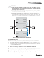
Press the OFF key (
) once and the LCD shows the following screen. If you want to
turn off the UPS, please press the DOWN key (
). Make sure the UPS is shutdown,
disconnect the UPS from the utility power, remove all equipment from the UPS, and store
the UPS in a dry and well-ventilated area at a temperature between -15°C and +50°C.
Idle batteries must be recharged fully approximately every three months if the UPS needs
to be stored for an extended period of time. The charging time must not be less than 24
hours each time.
OFF
6+87'2:1
?
<(6 12
Ultron HPH Series UPS
2
Chapter 1
1.5
Important Safety Instructions
Glossary of Symbols
No.
Symbol
Description
1
NORMAL
@
JK"
>
2
BATTERY
NJK"
>=
3
BYPASS
NJK"
>=
4
FAULT
;JK"
>
5
ON
6
OFF
OFF key
7
ESC
Goes back to previous screen or cancels current selection.
ON key
8
Moves down/ Decreases number.
9
Moves up/ Increases number.
10
X
EPO
11
EPO key
12
R
R phase of AC Input/ UPS Output
13
S
S phase of AC Input/ UPS Output
14
T
T phase of AC Input/ UPS Output
15
N
Input neutral line/ Output neutral line / Battery neutral line
16
For UPS grounding
17
For critical load grounding/ For external battery cabinet
grounding
18
Positive battery terminal
19
Negative battery terminal
3
1.6
Standard Compliance
This product meets the following safety standards and electromagnetic compatibility (EMC)
>
y
CE
y
IEC62040-1
y
GB7260.2-2009/ IEC62040-2 C2
y
GB17626-2/ IEC61000-4-2 (ESD) Level 4
y
GB17626-3/ IEC61000-4-3 (Radiated Field) Level 3
y
GB17626-4/ IEC61000-4-4 (EFT) Level 4
y
GB17626-5/ IEC61000-4-5 (Surge) Level 4
Ultron HPH Series UPS
4
Chapter 2
Introduction
Chapter 2 : Introduction
2.1
Product Introduction
The HPH series UPS is a three-phase four-wire online uninterruptible power supply which
provides reliable and stable sine-wave power to your electronic devices. The UPS applies the
latest design of DSP digital control technology and highest quality assembly, with an output
=
:
%
YZ
YYZ
KX@[
'*%
safe, reliable and uninterrupted power to your sensitive electronic equipment at all times, but
=
:
\*\
'*%
three different rated power levels, 20kVA, 30kVA and 40kVA, for your selection.
2.2
Package Inspection
y
External
During UPS transportation, some unpredictable situations might occur. It is recommended
that you inspect the UPS exterior packaging. If you notice any damage, please immediately contact the dealer from whom you purchased the unit.
y
Internal
1. Check the rating label on the top of the UPS cabinet and make sure the device No. and
capacity match what you ordered.
2. Examine if any parts are loose or damaged.
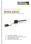
3. The UPS package contains the following items. Please check if any items are missing.
1
EPO
NORMAL
2
BATTERY
ON
OFF
BYPASS
3
4
FAULT
ESC
7
5
6
(Male) (Female)
(Male) (Male)
5
No.
Item
Quantity
1
UPS
1 pc
2
User Manual
1 pc
3
Test Card
1 pc
4
Software CD-UPSentry 2012
1 pc
5
RS232 Cable
1 pc
6
Parallel Cable
1 pc
7
Mini-card Flat Cable*1
1 pc
NOTE:
1. The balance supports have been locked on the pallet when the UPS is
shipped out of the factory. Please keep them well after unpacking. You might
use them for installation.
2.
*1 : The cable connects the UPS and a Delta Mini SNMP card, Mini USB card,
Mini Relay I/O card, or Mini Modbus card. The above-mentioned cards are optional. Please refer to Chapter 9: Optional Accessories.
4. If there is any damage or anything missing, please immediately contact the dealer from
whom you purchased the unit.
5. If the UPS needs to be returned, carefully repack the UPS and all of the accessories
using the original packing material that came with the unit.
2.3
Functions and Features
y
y
y
y
The HPH series UPS is designed for systems with medium power. It provides clean power
supply to data systems, communication systems, computer network systems, medical
treatment systems, monitoring systems, factory equipment, etc.
The HPH series UPS utilizes all digital high frequency modulation technology, which decreases volume, improves reliability and prolongs service life.
X
%^>_`{|`!{}}|~```}Z>_{|_`{!|
[
300Vac) reduces frequent transfer from normal mode to battery mode to save battery consumption and prolong battery life.
Battery test in online mode and regular battery test prolong battery life.
Ultron HPH Series UPS
6
Chapter 2
y
y
y
y
y
y
y
y
y
y
y
y
y
y
y
Introduction
Automatic input frequency detection enables operation at 50Hz or 60Hz.
You can parallel at maximum four UPS units for N+X parallel redundancy, capacity expansion and reliability enhancement.
It is convenient to set the parameters (output voltage, charging current, output frequency
and password setting, etc.) on the LCD panel.
The operating conditions, such as load, input and output voltage, input and output frequency, battery voltage, of the device are available on LCD so that management personnel can
see them accurately and clearly.
%JX">}!{}!~}
The CPU can record up to 200 entries of abnormal information of the UPS, which is helpful
'*
%
>$
%
still start up normally with normal AC.
K*@>'
=
nect the output immediately to prevent any danger.
Built-in RS232 port allows monitoring and management of the UPS via the UPSentry 2012
=^>!!====
!!
!=
Attaches optional accessories like SNMP and Mini SNMP cards for network communication.
Other optional accessories include Mini Relay I/O, Mini USB, Mini ModBus and Mini TVSS
cards for dry contact, USB communication, ModBus communication and surge protection.
%
'*
KX@
case of any abnormal conditions, the UPS will transfer to online mode automatically.
Automatically detects and shows whether fans are operating normally.
The fans have automatic speed regulation function. With multi-stage control over the fan
%
prolong the service life of the fans.
*%
#<_
maximum. Each adjustment level is 0.5A. The charging mode is set according to the actual
charging current so as to keep the batteries at full charging capacity and prolong the bat
^#%>`%>}
7
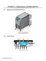
Chapter 3 : Appearance and Mechanism
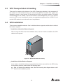
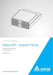
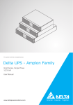
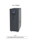
3.1
Appearance and Dimensions
EP
O
NORM
AL
BATT
ERY
BYPA
800
mm
SS
FAUL
T
ES
C
ON
OF
F
800
mm
380
mm
(Figure 3-1: 20/ 30/ 40kVA UPS
Appearance and Dimensions)
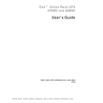
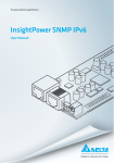
3.2
Front Panel
1
EPO
2
5
6
NORMAL
BATTERY
ON
BYPASS
FAULT
ESC
12
4
3
11
10
9
8
(Figure 3-2: Front Panel)
Ultron HPH Series UPS
8
OFF
7
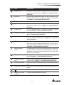
Chapter 3
No.
Item
Appearance and Mechanism
Description
1
NORMAL
This indicates that the UPS is operating in online mode and
the utility AC power is normal.
2
BATTERY
This indicates that the UPS is operating in battery mode and
the external batteries are discharging.
3
BYPASS
This indicates that the UPS is operating in bypass mode.
4
FAULT
This indicates that the UPS has abnormalities.
5
LCD Display
This displays the operating status of the UPS and the relevant monitoring data.
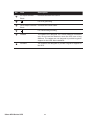
6
ON
ON>*
{|~
you hear a beep to start up the UPS.
OFF>*
JX"=lowing screen. To turn off the UPS, please press the DOWN
key (
).
7
OFF
6+87'2:1
?
<(6 12
8
X
9
Moves up/ Increases number.
10
Moves down/ Decreases number.
11
ESC
EPO
12
Goes back to previous screen or cancels current selection.
When an emergency event occurs, press the EPO key for
%_=
%
of the UPS immediately.
9
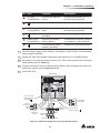
3.3
Rear Panel
1
1
2
MINI SLOT
SMART SLOT
MINI SLOT
SMART SLOT
2
3
3
4
5
PARALLEL
PARALLEL SWITCH
PARALLEL
RS232
MANUAL BYPASS SWITCH
1 2
ON
1
2
3
4
5
6
1
2
WARNING:
6
OUTPUT
DRY CONTACT
OPENING THIS COVER PLATE WILL
CAUSE INVERTER SHUTDOWN. ONLY
AUTHORIZED SERVICE PERSONNEL
CAN OPEN AND OPERATE IT.
INPUT
CHARGER
REPO
DRY CONTACT
DETECTION
9
4
10
11
5
6
7
8
8
I ON
I ON
I ON
I ON
I ON
I ON
I ON
I ON
O OFF
O OFF
O OFF
O OFF
O OFF
O OFF
O OFF
R
S
T
N
MAIN INPUT BREAKER
R
S
T
N
BYPASS INPUT BREAKER
2
R
T
S
OUTPUT BREAKER
12
13
13
3
4
5
6
1
MANUAL BYPASS SWITCH
10
2
WARNING:
OUTPUT
DRY CONTACT
OPENING THIS COVER PLATE WILL
CAUSE INVERTER SHUTDOWN. ONLY
AUTHORIZED SERVICE PERSONNEL
CAN OPEN AND OPERATE IT.
CHARGER
INPUT
REPO
DRY CONTACT
DETECTION
I ON
I ON
I ON
I ON
O OFF
O OFF
O OFF
O OFF
R
12
RS232
1 2
ON
1
7
O OFF
9
PARALLEL
PARALLEL SWITCH
PARALLEL
S
T
N
MAIN INPUT BREAKER
I ON
I ON
I ON
I ON
O OFF
O OFF
O OFF
O OFF
R
S
T
N
BYPASS INPUT BREAKER
11
R
T
S
OUTPUT BREAKER
14
15
N
R
S
T
N
R
AC INPUT
240V DC 240V DC
S
T
N
14
UPS OUTPUT
BATTERY INPUT
16
18
17
19
N
240V DC
240V DC
R
S
T
AC INPUT
N
R
S
T
N
UPS OUTPUT
BATTERY INPUT
20
17
20
21
21
(Figure 3-3: 20kVA Rear Panel)
1
(Figure 3-4: 30kVA Rear Panel)
2
MINI SLOT
SMART SLOT
3
4
5
9
PARALLEL
PARALLEL SWITCH
PARALLEL
RS232
1 2
ON
1
6
2
3
4
5
6
1
MANUAL BYPASS SWITCH
2
WARNING:
OPENING THIS COVER PLATE WILL
CAUSE INVERTER SHUTDOWN. ONLY
AUTHORIZED SERVICE PERSONNEL
CAN OPEN AND OPERATE IT.
CHARGER
INPUT
REPO
DRY CONTACT
DETECTION
OUTPUT
DRY CONTACT
10
11
7
8
I ON
I ON
I ON
I ON
I ON
I ON
I ON
I ON
O OFF
O OFF
O OFF
O OFF
O OFF
O OFF
O OFF
O OFF
S
R
T
N
R
MAIN INPUT BREAKER
S
T
N
R
S
BYPASS INPUT BREAKER
T
OUTPUT BREAKER
12
13
14
19
18
15
16
N
240V DC
R
240V DC
S
T
AC INPUT
N
R
S
T
N
UPS OUTPUT
BATTERY INPUT
19
18
15
16
17
20
21
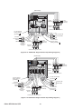
(Figure 3-5: 40kVA Rear Panel)
Ultron HPH Series UPS
10
Chapter 3
No.
Appearance and Mechanism
Item
Description
1
SMART Slot
Connects SNMP/ Relay I/O/ ModBus card. For detailed
information, please refer to Chapter 5 : Communication
Interfaces.
2
MINI Slot
Connects Mini SNMP/ Mini Relay I/O/ Mini USB/ Mini ModBus/ Mini TVSS card. For detailed information, please refer
to Chapter 5 : Communication Interfaces.
3
DC Fans
Cool and ventilate the UPS.
4
Parallel Switch
Controls parallel ports' status (ON or OFF). For detailed
information, please refer to Chapter 5 : Communication
Interfaces.
5
Parallel Ports
For UPS parallel usage. For detailed information, please
refer to Chapter 5 : Communication Interfaces.
6
Output Dry Contacts
Receive the UPS’s event information. Please refer to Chapter 5 : Communication Interfaces.
7
Input Dry Contacts
Receive external information of devices connected to the
input dry contacts. Please refer to Chapter 5 : Communication Interfaces.
8
REPO Port
When an emergency event occurs, it can disconnect the
UPS power supply rapidly and shut down the UPS safely
and immediately. For detailed information, please refer to
Chapter 5 : Communication Interfaces.
9
Manual Bypass
Switch
For maintenance only! Only authorized service personnel
can open the cover plate of the manual bypass switch and
operate it. Please note that opening this cover plate will
cause inverter shutdown.
10
RS232 Port
Connects to a computer. For detailed information, please
refer to Chapter 5 : Communication Interfaces.
11
Charger Detection
Port
Connects to a charger box and detects the charger status.
Please refer to Chapter 5 : Communication Interfaces.
12
Main Input Breaker
Controls the UPS’s main input switch and for safety protection.
13
Bypass Input Breaker Controls the UPS’s bypass power switch and for safety protection.
For external battery cabinet grounding.
14
15
Battery Input Terminal Block
Connects an external battery cabinet.
11
No.
16
Item
Description
AC Input Terminal
Block
Connects the main AC source.
For UPS grounding.
17
18
UPS Output Terminal Connects the critical loads.
Block
19
For critical load grounding.
20
Casters
The casters are designed for a short distance movement
only. Do not use the casters to move the UPS over a long
distance. The casters are not designed to provide long-term
support for the UPS after installation.
21
Levelers
The levelers are designed to provide long-term support for
the UPS.
Ultron HPH Series UPS
12
Chapter 4
Operation Modes
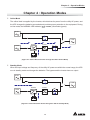
Chapter 4 : Operation Modes
y
Online Mode
The critical load is supplied by the inverter, which derives its power from the utility AC power, and
the UPS charges the batteries as needed and provides power protection to the equipment. During
NORMAL ) illuminates (green).
on-line mode, the NORMAL LED indicator (
BYPA.
LOAD
Rectifier
Inverter
MAIN
Batteries
(Figure 4-1: Path of Electrical Power through the UPS in Online Mode)
y
Standby Mode
When the input voltage and frequency of the utility AC power are within the normal range, the UPS
runs in standby mode and charges the batteries. The bypass and the inverter have no output.
BYPA.
LOAD
Rectifier
Inverter
MAIN
Batteries
(Figure 4-2: Path of Electrical Power through the UPS in Standby Mode)
13
y
ECO Mode
You can manually set the UPS to ECO mode. In ECO mode, when the utility input voltage is within
%_}Z
=N<*JK"
BYPASS
^=
%
indicator (
NORMAL ) illuminates (green).
and the NORMAL LED indicator (
BYPA.
LOAD
Rectifier
Inverter
MAIN
Batteries
(Figure 4-3: Path of Electrical Power through the UPS in ECO Mode)
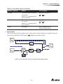
y
Battery Mode
When the UPS is operating during a power outage, the batteries provide DC power, which maintains inverter operation to support the critical load. During battery mode, the BATTERY LED indicaBATTERY ) illuminates (yellow).
tor (
BYPA.
LOAD
Rectifier
Inverter
MAIN
Batteries
(Figure 4-4: Path of Electrical Power through the UPS in Battery Mode)
Ultron HPH Series UPS
14
Chapter 4
Operation Modes
Table 4-1: The battery status is as follows
Battery Capacity
Buzzer
LCD Display
Full/ Mid
The alarm beeps once every
10 seconds.
BATTERY CAPACITY
00V/ 000Z
(ON for 0.1 second and OFF
for 9.9 seconds)
Low
The alarm beeps once every
0.5 second.
BATTERY CAPACITY
00V/ 000Z
(ON for 0.1 second and OFF
for 0.4 second)
Under
y
Long beep
SHUT DOWN DUE TO
DEPLETED BATTERY
Bypass Mode
The critical load is directly supplied by the utility power and the batteries are charged. During byBYPASS ) illuminates (yellow).
pass mode, the BYPASS LED indicator (
BYPA.
LOAD
Rectifier
Inverter
MAIN
Batteries
(Figure 4-5: Path of Electrical Power through the UPS in Bypass Mode)
15
y
Converter Mode
When the UPS is manually set in converter mode, the output frequency can be set as 50Hz or
60Hz. After the output frequency is set up, the system will automatically disable the bypass function. Please note that once the inverter shuts down, there is no bypass output. During converter
NORMAL ) illuminates (green).
mode, the NORMAL LED indicator (
BYPA.
LOAD
Rectifier
Inverter
MAIN
Batteries
(Figure 4-6: Path of Electrical Power through the UPS in Converter Mode)
Ultron HPH Series UPS
16
Chapter 5
Communication Interfaces
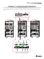
Chapter 5 : Communication Interfaces
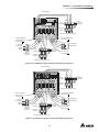
For the positions and functions of the communication interfaces, please refer to the following description.
1
2
MINI SLOT
SMART SLOT
(20kVA Model)
MINI SLOT
SMART SLOT
PARALLEL
PARALLEL SWITCH
PARALLEL
2
3
4
5
6
1
PARALLEL
PARALLEL SWITCH
PARALLEL
RS232
RS232
1
2
3
4
5
6
1
OUTPUT
DRY CONTACT
1
I ON
I ON
I ON
I ON
I ON
I ON
I ON
I ON
I ON
I ON
I ON
I ON
I ON
I ON
I ON
O OFF
O OFF
O OFF
O OFF
O OFF
O OFF
O OFF
O OFF
O OFF
O OFF
O OFF
O OFF
O OFF
O OFF
O OFF
N
R
S
T
N
BYPASS INPUT BREAKER
240V DC 240V DC
R
S
T
AC INPUT
N
R
R
T
S
OUTPUT BREAKER
R
S
2
3
4
5
6
1
MANUAL BYPASS SWITCH
2
T
S
T
N
MAIN INPUT BREAKER
N
UPS OUTPUT
R
S
T
N
BYPASS INPUT BREAKER
N
240V DC
BATTERY INPUT
240V DC
R
WARNING:
OPENING THIS COVER PLATE WILL
CAUSE INVERTER SHUTDOWN. ONLY
AUTHORIZED SERVICE PERSONNEL
CAN OPEN AND OPERATE IT.
CHARGER
INPUT
REPO
DRY CONTACT
DETECTION
I ON
S
T
N
MAIN INPUT BREAKER
RS232
1 2
ON
MANUAL BYPASS SWITCH
2
WARNING:
OPENING THIS COVER PLATE WILL
CAUSE INVERTER SHUTDOWN. ONLY
AUTHORIZED SERVICE PERSONNEL
CAN OPEN AND OPERATE IT.
O OFF
R
PARALLEL
PARALLEL SWITCH
PARALLEL
1 2
ON
MANUAL BYPASS SWITCH
2
INPUT
CHARGER
REPO
DRY CONTACT
DETECTION
MINI SLOT
SMART SLOT
WARNING:
OUTPUT
DRY CONTACT
(40kVA Model)
MINI SLOT
SMART SLOT
1 2
ON
1
(30kVA Model)
S
T
N
R
AC INPUT
S
T
3
5
4
OUTPUT
DRY CONTACT
6
6
I ON
I ON
I ON
I ON
O OFF
O OFF
O OFF
O OFF
S
T
N
N
240V DC
5
PARALLEL
PARALLEL SWITCH
4
I ON
O OFF
240V DC
BATTERY INPUT
RS232
1 2
ON
2
I ON
O OFF
N
UPS OUTPUT
3
1
I ON
O OFF
1
2
CHARGER
INPUT
REPO
DRY CONTACT
DETECTION
7
8
9
(Figure 5-1: Communication Interfaces)
17
R
MAIN INPUT BREAKER
BATTERY INPUT
PARALLEL
I ON
O OFF
R
R
T
S
OUTPUT BREAKER
OPENING THIS COVER PLATE WILL
CAUSE INVERTER SHUTDOWN. ONLY
AUTHORIZED SERVICE PERSONNEL
CAN OPEN AND OPERATE IT.
CHARGER
INPUT
REPO
DRY CONTACT
DETECTION
OUTPUT
DRY CONTACT
S
T
N
R
S
BYPASS INPUT BREAKER
R
S
T
AC INPUT
N
OUTPUT BREAKER
R
S
T
UPS OUTPUT
N
T
NOTE:
1. The UPS can still function properly without making the connections below.
2. You can use all of the communication interfaces at the same time and it will not influence
each interface’s function.
1 SMART Slot
Install an SNMP card in this SMART slot to remotely control and monitor the UPS status via a network. You can also insert the Relay I/O or ModBus card in this slot to let the UPS have dry contact
and ModBus communication functions respectively.
2 MINI Slot
This MINI slot is for mini cards. You can install a Delta Mini SNMP, Mini Relay I/O, Mini USB, Mini
ModBus, or Mini TVSS card in this slot to give the system network communication, dry contact,
USB communication, ModBus communication, and surge protection functions respectively. Please
note that you need to use the provided mini-card flat cable to connect the MINI slot and the UPS’s
CNY7 connector if you use a Delta Mini SNMP card, Mini USB card, Mini Relay I/O card, or Mini
Modbus card. For installation information, please contact service personnel.
3 Parallel Ports
The two parallel ports are for UPS parallel communication. UPSs (at maximum four) with the
same capacity, voltage and frequency can be coupled via the provided parallel cable to run in parallel mode.
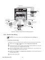
4 Parallel Switch
When you parallel UPSs, you need to set up the parallel switch to activate parallel function. The
parallel switch includes two DIP switches. To turn on a DIP switch, switch the DIP to the down po
"*=
=
"*
1. When two UPSs are paralleled, turn on each UPS’s DIP switches.
OFF
2. When three UPSs are paralleled, turn off the middle UPS’s DIP
switches and turn on the remaining UPSs' DIP switches.
1
1ON2
2
ON
3. When four UPSs are paralleled, turn off the middle two UPSs’
DIP switches and turn on the remaining UPSs’ DIP switches.
(Figure 5-2: Parallel Switch)
Ultron HPH Series UPS
18
ON
Chapter 5
Communication Interfaces
5 RS232 Port
The RS232 port is built into the UPS rear panel to provide communication between the UPS and
a computer. It also provides dry contact functions to output the UPS status. You can use the Delta
UPSentry 2012 = ^>!!====
!!
!=
'*%
"
=>
1. Monitors the load level, battery status, battery voltage, UPS operation mode, input voltage,
input frequency, output voltage, and UPS temperature.
2. Sets shutdown delay time.
3. Enables/ disables beep.
5 4 3 2 1
4. Supports remote shutdown.
*
>
_ *>:":
"
*{>
"
%
"
{ *>"
9 8 7 6
6. Hardware
(Figure 5-3: RS232 Port)
_ N
>~}}
"J>
{ N
>_
~ *
>
NOTE: Other pins are reserved and cannot be used.
19
6 Output Dry Contacts
DRY F_NO
+12VS
4
1
3
2
COMM_F
DRY E_NO
4
1
3
2
COMM_E
2
COMM_C
DRY B_NO
3
DRY 4
+12VS
1
2
DRY C_NO
3
1
COMM_D
4
Pin 1 2 3 4 5 6 7 8 9 10 11 12
Pin 1 2 3 4 5 6 7 8 9 10 11 12
5
6
4
5
2
4
1
3
3
2
DRY 5
+12VS
4
6
DRY D_NO
1
DRY 6
+12VS
DRY 3
+12VS
1
4
COMM_B
2
3
DRY A_NO
DRY 2
+12VS
1
4
COMM_A
2
3
DRY 1
UPS
(Figure 5-4: )
The HPH UPS provides six sets of programmable output dry contacts for you to receive UPS
events. The output dry contacts are normally open. There are eighteen events for you to select,
and you can choose six of them to set up the output dry contacts. Please refer to the table below.
No.
1
Event
Description
Load on inverter
1. The UPS works in normal mode.
2. ">*
_
2
Load on bypass
1. The UPS works in bypass mode.
2. ">*
{~
3
Battery discharge/
Main input NOK
1. When the main AC source fails, it is the batteries to
supply power to the equipment loads.
2. ">*
Ultron HPH Series UPS
20
Chapter 5
No.
4
Communication Interfaces
Event
Description
Low battery
1. When the UPS runs in battery mode, battery voltage is
lower than setup limit, 220Vdc.
2. ">*
`
5
Bypass input NOK
1. The bypass voltage, frequency or phase sequence is
abnormal.
2. ">*
Y_}
6
Battery test fail or battery
missing
1. In the process of battery test, battery voltage is out of
setup limit.
2. ">*
___
7
Internal communication
failure
Power unit’s internal communication is abnormal.
8
External parallel communication loss
In parallel mode, parallel communication is abnormal.
9
Output overload warning/
shutdown
The UPS is overloaded or the UPS shuts down to let the
bypass supply power to the equipment loads.
10
EPO activated
The EPO button is pressed to urgently power off the UPS.
11
Load on manual bypass
The Manual Bypass Switch is turned on and the UPS
transfers to manual bypass mode.
12
Battery cabinet over temperature warning/ shutdown
The external battery cabinet’s temperature is too high.
13
Abnormal inverter voltage
The output voltage is too high or too low.
14
Battery needs replacement
Battery replacement date is due.
15
Bypass over temperature
warning/ shutdown
Bypass static switch temperature is too high.
16
Bypass static switch fail
The bypass static switch has open/ short issue.
17
Over temperature fail
When the UPS temperature is out of range.
18
General alarm
When any of above-mentioned events occurs.
21
7 Input Dry Contacts
The HPH UPS provides two sets of input dry contacts and they are normally open. The default setting for Pin 1 & 2 is ‘ROO’ and the default setting for Pin 3 & 4 is ‘Generator Power Supply Signal’.
There are two types of configurations.
1
2
Pin 1
Pin 2
Pin 4
Pin 3
(Figure 5-5: Input Dry Contacts)
Figure 5-6 shows the 1st type of input dry contact configuration. It requires internal power, +12VSF.
6
1
4
3
2K(1206)
2K(1206)
GS
+12VSF
6
1
4
3
1
2
3
4
2K(1206)
2K(1206)
GS
UPS
(Figure 5-6: Input Dry Contact Configuration I)
Figure 5-7 shows the 2nd type of input dry contact configuration. It requires external power with a
%=|_
6
1
4
3
2K(1206)
2K(1206)
GS
+12VSF
6
1
4
3
2K(1206)
2K(1206)
GS
UPS
(Figure 5-7: Input Dry Contact Configuration II)
Ultron HPH Series UPS
22
1
2
3
4
+
Chapter 5
Communication Interfaces
8 REPO Port
The REPO port is for remote emergency shutdown. When an emergency event occurs, it can disconnect the UPS power supply rapidly and shut down the UPS immediately. The configuration is
==
+
$==
%=|_
6
4
UX6
2K
1
2K
3
1
+
2
GS
UPS
(Figure 5-8: REPO Port Configuration)
9 Charger Detection Port
The charger detection port is used to connect with an external charger box. Via this port, the UPS
can detect the operating status of the external charger box and control its switch.
23
Chapter 6 : Installation and Wiring
6.1
Precautions Prior to Installation and Wiring
Due to different installation environments, it is highly recommended that you read this user
manual before installation. Only authorized Delta engineers or service personnel can perform
installation and maintenance. If you want to install the UPS by yourself, installation must be
under the supervision of authorized Delta engineers or service personnel. If you use a forklift
+
%'*
;
weight of the UPS, please refer to .
6.2
Installation Environment
y
y
y
y
Install the UPS indoors. Do not place it outdoors.
Make sure that transportation routes (e.g. corridor, door gate, elevator, etc.) and installation
area can accommodate and bear the weight of the UPS, external battery cabinets, other
equipment that will be installed nearby and forklifts. For the weight of the UPS, please refer
to .
The installation place must be kept clean and tidy at all times.
Ensure that the installation area is big enough for maintenance and ventilation. Since the
fans of the UPS ventilate from front to rear, and it is recommended that you place the ex
$'*=>
1. Keep a distance of 100cm from the front of the UPS and the external battery cabinet
for maintenance and ventilation.
2. Keep a distance of 50cm from the back of the UPS and the external battery cabinet for
maintenance and ventilation.
3. Keep a distance of 50cm from the both sides of the UPS and the external battery cabinet for maintenance and ventilation.
y
}X|~}X
=
YZ:
highest operating altitude is 1000 meters above sea level.
WARNING:
Do not use air conditioners or similar equipment to blow into the rear side of the
UPS and hinder ventilation.
Ultron HPH Series UPS
24
Chapter 6
6.3
Installation and Wiring
UPS Transportation & Handling
There are four casters at the bottom of the UPS. Please pay attention to the movement of
the casters to avoid accidents when you remove the UPS from its pallet. The casters are
designed to move on level ground. Do not move the UPS on an uneven surface. This might
cause damage to the casters or tip the UPS which could damage the unit. If you need to
move the UPS over a long distance, please use appropriate equipment like a forklift. Do not
use the UPS casters to move the unit over a long distance.
6.4
UPS Installation
There are two installation methods. One is with the balance supports, and the other is without
the balance supports.
y
Installation without the Balance Supports
%
'*
%
'*
cabinet on the ground.
EPO
NORM
AL
BATTE
RY
BYPA
SS
FAULT
ES
C
ON
OFF
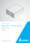
(Figure 6-1: Stabilize the UPS with Levelers)
y
Installation with the Balance Supports
If you want to reinstall the balance supports that have been removed from the UPS during
the unpacking process, please follow the following steps.
1
After you decide the installation area, follow the mounting hole diagram below to drill
holes on the installation ground.
25
150.3
mm
(Front)
Mounting
Hole (Diameter:
Ø10.4 mm)
548.8
mm
Balance
Supports
102
mm
Casters
440 mm
(Back)
(Figure 6-2: Mounting Hole Diagram)
2
Move the UPS on the installation ground that you have drilled holes, use the levelers
to stabilize the UPS on the ground and use the M6 screws to reinstall the balance
supports (that have been removed from the UPS during the unpacking process) on
'**=
M6 Screw x 8
EPO
NORM
AL
BATTE
RY
BYPA
SS
FAULT
ES
C
ON
OFF
Balance Support x 4
(Figure 6-3: Balance Support Installation)
Ultron HPH Series UPS
26
Chapter 6
Installation and Wiring
3 '$
=$%
UPS movement. Please note that service personnel should provide the expansion
=*=
Balance
Support x 4
EPO
NORM
AL
BATTE
RY
BYPA
SS
FAULT
ES
C
Ground
ON
OFF
M8 Expansion
Screw x 4
(Figure 6-4: Fix the Balance Supports on the Ground)
6.5
Wiring
6.5.1 Precautions Prior to Wiring
y
y
y
=
+
=
:
UPS by yourself, installation must be under the supervision of authorized Delta engineers
or service personnel.
Before wiring or making any electrical connection, make sure the power supplied to the input and output of the UPS is completely cut off.
When connecting the UPS to the utility AC power and bypass source, you must install the
protective devices and 4-pole contactors. The protective devices and 4-pole contactors
%
*
below for suggested protective devices and suppliers. For the installation of the protective
devices and 4-pole contactors, please see Figure 6-9~6-17.
27
UPS
Suggested Protective Device
Suggested Supplier
20kVA
D-Curve 63A circuit breaker
N>X\:^XN}"
30/ 40kVA D-Curve 125A circuit breaker
y
y
N>X\:^XN_"_
When connecting the UPS to the critical loads, you must install a 3-pole EN 60947-2 certi=*=
UPS
Suggested 3-pole Breaker
Suggested Supplier
20KVA
C-Curve 63A Breaker
@>X\:^XN}X{
30KVA
C-Curve 63A Breaker
@>X\:^XN}X{
40KVA
C-Curve 100A Breaker
@>X\:^XN_X_}}
Check that the size, diameter, phase, and polarity of each cable that needs connecting
'*
;
!
please refer to Table 6-1.
!"
Capacity (kVA)
20kVA
30kVA
40kVA
AC Input cable
8AWG/ 6mm²
6AWG/ 10mm²
4AWG/ 16mm²
Output cable
8AWG/ 6mm²
6AWG/ 10mm²
4AWG/ 16mm²
Battery Input cable
6AWG/ 10mm²
4AWG/ 16mm²
2AWG/ 25mm²
Tightening Torque
20.4 Kgf.cm
61.2 kgf.cm
61.2 kgf.cm
Main Input Breaker
63A (4-pole×1)
63A (4-pole×1)
100A (4-pole×1)
Bypass Input Breaker
63A (4-pole×1)
63A (4-pole×1)
100A (4-pole×1)
NOTE:
1. In accordance with National Electrical Codes (NEC), please install a suitable
conduit and bushing.
2. Please refer to national and local electrical codes for acceptable non-fuse
breakers and cable size.
3. Cables with PVC material and with temperature resistance up to 105°C are
suggested.
4. Make sure that the input/ output cables are locked tightly.
Ultron HPH Series UPS
28
Chapter 6
y
y
y
y
=
$
"[
verse the polarity.
The grounding cable of the external battery cabinet must be connected to the (
nal of the battery terminal block.
y
y
y
) termi-
The UPS default setting is single input. If there is an intention to change the UPS into dual
+
%
Please check whether the electric potential of the neutral line (N) of the bypass source is
the same as that of the neutral line (N) of the main AC source. If they do not share a common neutral line system, add an isolation transformer to the bypass source.
The input of the UPS must be a Y connection, and the neutral line (N) must be connected
to avoid UPS failure. Do not connect the neutral line (N) of the UPS with the ground terminal (
y
Installation and Wiring
).
#
%=
= (N) and the ground (
),
and you require that the VNG of the UPS should be zero, we suggest that you install an
isolation transformer in front of the input side of the UPS, and connect the UPS neutral (N)
with the ground (
).
X=^
!!:
:
on the UPS’s rating label. When connecting the utility input power to the UPS, make sure it
is in positive phase sequence.
)
Connect the external battery cabinet’s grounding terminal to the grounding terminal (
of the UPS’s battery terminal block. Do not connect the grounding terminal of the external
battery cabinet to any other grounding system.
The ground terminal (
nal for wiring.
) of the UPS must be grounded, and please use ring-type termi-
WARNING:
1. Incorrect wiring will lead to severe electric shock and damage to the UPS.
2. The UPS will not work normally if the input power's neutral (N) is not firmly connected or not connected to the AC Input Block's neutral (N) terminal.
29
#$#% '+,
WARNING:
1. Only authorized Delta engineers or service personnel can modify single input/
dual input setup.
2. For dual input, the main AC source’s Neutral (N) must be connected with the bypass source’s Neutral (N).
The UPS default setting is single input. If you want to modify it into dual input, please follow
the following steps.
1
%=
=
(20kVA Model)
MINI SLOT
SMART SLOT
PARALLEL
PARALLEL SWITCH
PARALLEL
2
3
4
5
6
1
PARALLEL
PARALLEL SWITCH
PARALLEL
RS232
1
OPENING THIS COVER PLATE WILL
CAUSE INVERTER SHUTDOWN. ONLY
AUTHORIZED SERVICE PERSONNEL
CAN OPEN AND OPERATE IT.
2
3
4
5
6
1
PARALLEL
PARALLEL SWITCH
PARALLEL
RS232
1 2
ON
MANUAL BYPASS SWITCH
2
INPUT
CHARGER
REPO
DRY CONTACT
DETECTION
MINI SLOT
SMART SLOT
RS232
1 2
ON
MANUAL BYPASS SWITCH
1
2
2
3
4
5
6
1
MANUAL BYPASS SWITCH
2
WARNING:
WARNING:
OUTPUT
DRY CONTACT
(40kVA Model)
MINI SLOT
SMART SLOT
1 2
ON
1
(30kVA Model)
OUTPUT
DRY CONTACT
OPENING THIS COVER PLATE WILL
CAUSE INVERTER SHUTDOWN. ONLY
AUTHORIZED SERVICE PERSONNEL
CAN OPEN AND OPERATE IT.
CHARGER
INPUT
REPO
DRY CONTACT
DETECTION
I ON
I ON
I ON
I ON
I ON
I ON
I ON
I ON
I ON
I ON
I ON
I ON
I ON
I ON
I ON
I ON
O OFF
O OFF
O OFF
O OFF
O OFF
O OFF
O OFF
O OFF
O OFF
O OFF
O OFF
O OFF
O OFF
O OFF
O OFF
O OFF
WARNING:
OPENING THIS COVER PLATE WILL
CAUSE INVERTER SHUTDOWN. ONLY
AUTHORIZED SERVICE PERSONNEL
CAN OPEN AND OPERATE IT.
CHARGER
INPUT
REPO
DRY CONTACT
DETECTION
OUTPUT
DRY CONTACT
I ON
I ON
I ON
I ON
I ON
I ON
I ON
I ON
O OFF
O OFF
O OFF
O OFF
O OFF
O OFF
O OFF
O OFF
(Figure 6-5: Panel Location)
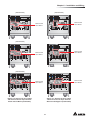
2
After removing the panels, please select either of the following methods to modify the
UPS from single input into dual input.
1. Remove the four cables that connect the AC input terminal block and the main input
breaker (please see Figure 6-6). When wiring, connect the main AC source’s R, S, T
and N cables to the main input breaker.
2. Or remove the four cables that connect the AC input terminal block and the bypass
input breaker (please see Figure 6-7). When wiring, connect the bypass source’s R,
S, T and N cables to the bypass input breaker.
Ultron HPH Series UPS
30
Chapter 6
(20kVA Model)
(20kVA Model)
I ON
I ON
I ON
I ON
I ON
I ON
I ON
I ON
O OFF
O OFF
O OFF
O OFF
O OFF
O OFF
O OFF
O OFF
R
S
T
N
MAIN INPUT BREAKER
R
S
T
N
BYPASS INPUT BREAKER
Installation and Wiring
I ON
I ON
I ON
I ON
I ON
I ON
I ON
I ON
O OFF
O OFF
O OFF
O OFF
O OFF
O OFF
O OFF
O OFF
R
R
T
S
OUTPUT BREAKER
S
T
N
MAIN INPUT BREAKER
R
S
T
N
BYPASS INPUT BREAKER
R
T
S
OUTPUT BREAKER
Remove the
four cables
Remove the
four cables
N
R
S
T
N
R
S
AC INPUT
240V DC 240V DC
T
N
N
R
S
T
N
R
S
AC INPUT
240V DC 240V DC
UPS OUTPUT
T
N
UPS OUTPUT
BATTERY INPUT
BATTERY INPUT
(30kVA Model)
I ON
I ON
I ON
I ON
I ON
I ON
I ON
I ON
O OFF
O OFF
O OFF
O OFF
O OFF
O OFF
O OFF
O OFF
R
S
T
N
MAIN INPUT BREAKER
R
S
T
N
BYPASS INPUT BREAKER
I ON
I ON
I ON
I ON
I ON
I ON
I ON
I ON
O OFF
O OFF
O OFF
O OFF
O OFF
O OFF
O OFF
O OFF
R
R
T
S
OUTPUT BREAKER
S
T
N
MAIN INPUT BREAKER
R
S
T
N
BYPASS INPUT BREAKER
R
T
S
OUTPUT BREAKER
Remove the
four cables
Remove the
four cables
N
240V DC
R
S
T
N
R
AC INPUT
240V DC
S
T
N
N
240V DC
UPS OUTPUT
R
S
T
N
R
AC INPUT
240V DC
S
T
N
UPS OUTPUT
BATTERY INPUT
BATTERY INPUT
(40kVA Model)
I ON
I ON
I ON
I ON
I ON
I ON
I ON
I ON
O OFF
O OFF
O OFF
O OFF
O OFF
O OFF
O OFF
O OFF
S
R
T
N
R
MAIN INPUT BREAKER
S
T
N
R
S
BYPASS INPUT BREAKER
I ON
I ON
I ON
I ON
I ON
I ON
I ON
I ON
O OFF
O OFF
O OFF
O OFF
O OFF
O OFF
O OFF
O OFF
R
T
S
T
N
R
MAIN INPUT BREAKER
OUTPUT BREAKER
S
T
N
R
S
BYPASS INPUT BREAKER
T
OUTPUT BREAKER
Remove the
four cables
Remove the
four cables
N
240V DC
240V DC
R
S
T
AC INPUT
N
R
S
T
N
N
240V DC
UPS OUTPUT
240V DC
R
S
T
AC INPUT
N
R
S
T
N
UPS OUTPUT
BATTERY INPUT
BATTERY INPUT
(Figure 6-6: Remove the Four Cables
that Connect the AC Input Terminal
Block and the Main Input Breaker)
(Figure 6-7: Remove the Four Cables
that Connect the AC Input Terminal
Block and the Bypass Input Breaker)
31
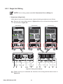
6.5.3 Single Unit Wiring
NOTE: Prior to wiring, please read 6.5.1 Precautions Prior to Wiring
y
Single Input (Single Unit)
When there is only one AC power source, single unit wiring procedures are as follows.
1
Remove the cover plates shown in Figure 6-5 and you will see the wiring terminal
block shown in Figure 6-8.
(20kVA Model)
MINI SLOT
SMART SLOT
PARALLEL
PARALLEL SWITCH
PARALLEL
2
3
4
5
6
1
PARALLEL
PARALLEL SWITCH
PARALLEL
RS232
RS232
1
2
3
4
5
6
1
1
I ON
I ON
I ON
I ON
I ON
I ON
I ON
I ON
I ON
I ON
I ON
I ON
I ON
I ON
I ON
O OFF
O OFF
O OFF
O OFF
O OFF
O OFF
O OFF
O OFF
O OFF
O OFF
O OFF
O OFF
O OFF
O OFF
O OFF
N
R
S
T
N
BYPASS INPUT BREAKER
R
S
T
R
R
T
S
OUTPUT BREAKER
N
R
AC INPUT
240V DC 240V DC
S
2
3
T
S
T
N
MAIN INPUT BREAKER
N
UPS OUTPUT
R
S
T
N
BYPASS INPUT BREAKER
N
240V DC
BATTERY INPUT
N
240V DC 240V DC
S
T
6
1
MANUAL BYPASS SWITCH
2
240V DC
R
S
T
AC INPUT
N
R
S
T
N
R
AC INPUT
S
T
OPENING THIS COVER PLATE WILL
CAUSE INVERTER SHUTDOWN. ONLY
AUTHORIZED SERVICE PERSONNEL
CAN OPEN AND OPERATE IT.
CHARGER
INPUT
REPO
DRY CONTACT
DETECTION
I ON
I ON
I ON
I ON
I ON
I ON
I ON
I ON
O OFF
O OFF
O OFF
O OFF
O OFF
O OFF
O OFF
O OFF
R
R
T
S
OUTPUT BREAKER
S
T
N
R
S
MAIN INPUT BREAKER
N
UPS OUTPUT
N
240V DC
T
N
R
S
BYPASS INPUT BREAKER
R
S
T
N
AC INPUT
240V DC
T
OUTPUT BREAKER
R
S
T
N
UPS OUTPUT
BATTERY INPUT
R
5
OUTPUT
DRY CONTACT
BATTERY INPUT
4
WARNING:
OPENING THIS COVER PLATE WILL
CAUSE INVERTER SHUTDOWN. ONLY
AUTHORIZED SERVICE PERSONNEL
CAN OPEN AND OPERATE IT.
CHARGER
INPUT
REPO
DRY CONTACT
DETECTION
OUTPUT
DRY CONTACT
I ON
S
T
N
MAIN INPUT BREAKER
RS232
1 2
ON
MANUAL BYPASS SWITCH
2
WARNING:
OPENING THIS COVER PLATE WILL
CAUSE INVERTER SHUTDOWN. ONLY
AUTHORIZED SERVICE PERSONNEL
CAN OPEN AND OPERATE IT.
O OFF
R
PARALLEL
PARALLEL SWITCH
PARALLEL
1 2
ON
MANUAL BYPASS SWITCH
2
INPUT
CHARGER
REPO
DRY CONTACT
DETECTION
MINI SLOT
SMART SLOT
WARNING:
OUTPUT
DRY CONTACT
(40kVA Model)
MINI SLOT
SMART SLOT
1 2
ON
1
(30kVA Model)
N
N
240V DC
R
S
T
N
R
S
AC INPUT
240V DC
T
N
UPS OUTPUT
BATTERY INPUT
UPS OUTPUT
BATTERY INPUT
+N-
R S T N
5
1
6
R S T N
2
4
3
6
+N-
R S T N
5
1
R S T N
2
3
4
(Figure 6-8: Wiring Terminal Block)
2
Please ensure you understand the functions of the wiring terminal block shown in
Figure 6-8.
Ultron HPH Series UPS
32
Chapter 6
No. Item
1
AC Input
Terminal Block
2
3
UPS Output
Terminal Block
4
5
Battery Input
Terminal Block
6
3
Installation and Wiring
Function
Description
Connects the main AC
source.
Includes three-phase (R, S, T)
and neutral (N) terminals.
For the UPS grounding
Includes one grounding terminal.
Connects the critical
loads.
Includes three-phase (R, S, T)
and neutral (N) terminals.
For the critical loads’
grounding
Includes one grounding terminal.
Connects an external
battery cabinet.
Includes three terminals, positive
(+), negative (-) and neutral (N).
For the external battery
cabinet’s grounding
Includes one grounding terminal.
The UPS rating voltage is 220/ 380Vac, 230/ 400Vac or 240/ 415Vac, and the battery
rating voltage is ±240Vdc.
4 X
OFF position.
5
According to the capacity and the model of your UPS, select proper input and output
cables (please refer to Table 6-1).
6
Connect the main AC source/ output/ external battery cabinet cables to the wiring terminal block (please refer to Figure 6-9~6-11).
7
Ground the UPS.
(20kVA Model)
I ON
I ON
I ON
I ON
I ON
I ON
I ON
I ON
O OFF
O OFF
O OFF
O OFF
O OFF
O OFF
O OFF
O OFF
R
S
T
N
MAIN INPUT BREAKER
N
R
S
T
N
BYPASS INPUT BREAKER
240V DC 240V DC
R
S
T
R
T
S
OUTPUT BREAKER
N
R
AC INPUT
S
T
N
UPS OUTPUT
BATTERY INPUT
For the external
battery cabinet’s
grounding
Connects +
the external N
battery cabinet
Protective
Device
(Disconnect
Device)
N
For the
UPS
grounding
Connects the
critical loads
3-Pole Breaker
R S T N
4-Pole
Contactor
T
S
R
CS
R S T N
(*CS:
Contactor
Solenoid)
For the critical
loads’ grounding Protective
Device
R S T N
Connects the main AC source
(Figure 6-9: 20kVA UPS Single Unit Single Input Wiring Diagram)
33
(30kVA Model)
I ON
I ON
I ON
I ON
I ON
I ON
I ON
I ON
O OFF
O OFF
O OFF
O OFF
O OFF
O OFF
O OFF
O OFF
R
S
T
N
MAIN INPUT BREAKER
R
S
T
N
BYPASS INPUT BREAKER
N
240V DC
R
R
T
S
OUTPUT BREAKER
S
T
N
R
S
AC INPUT
240V DC
T
N
UPS OUTPUT
BATTERY INPUT
For the critical loads’
grounding
For the external
battery cabinet’s
grounding
Connects
the external
battery
cabinet
N
T
S
R
+
N
Protective
Device
(Disconnect
Device)
R S T N
4-Pole
Contactor
(*CS:
Contactor
Solenoid)
CS
R S T N
Connects the
critical loads
3-Pole Breaker
For the UPS
grounding
Protective
Device
R S T N
Connects the main AC source
(Figure 6-10: 30kVA UPS Single Unit Single Input Wiring Diagram)
(40kVA Model)
I ON
I ON
I ON
I ON
I ON
I ON
I ON
I ON
O OFF
O OFF
O OFF
O OFF
O OFF
O OFF
O OFF
O OFF
R
S
T
N
R
MAIN INPUT BREAKER
N
240V DC
240V DC
S
T
N
R
S
BYPASS INPUT BREAKER
R
S
T
N
AC INPUT
T
OUTPUT BREAKER
R
S
T
N
UPS OUTPUT
BATTERY INPUT
For the critical loads’
grounding
For the external
battery cabinet’s
grounding
Connects
the external
battery
cabinet
N
T
S
R
+
N
Protective
Device
(Disconnect
Device)
R S T N
4-Pole
Contactor
CS
R S T N
(*CS:
Contactor
Solenoid)
3-Pole Breaker
For the UPS
grounding
Protective
Device
R S T N
Connects the main AC source
(Figure 6-11: 40kVA UPS Single Unit Single Input Wiring Diagram)
Ultron HPH Series UPS
34
Connects the
critical loads
Chapter 6
y
Installation and Wiring
Dual Input (Single Unit)
When there are two AC power sources, single unit wiring procedures are as follows.
1
Follow !"#$#% to modify the UPS into dual input. Please note that only authorized Delta engineers or service personnel can modify single input/ dual input setup.
2
Please follow steps 1 | 5 stated in section Single Input (Single Unit).
3
Connect the main AC source/ bypass source/ output/ external battery cabinet cables
to the wiring terminal block (please refer to Figure 6-12~6-17).
4
Ground the UPS.
(20kVA Model)
I ON
I ON
I ON
I ON
I ON
I ON
I ON
I ON
O OFF
O OFF
O OFF
O OFF
O OFF
O OFF
O OFF
O OFF
R
S
T
N
MAIN INPUT BREAKER
R
S
T
N
BYPASS INPUT BREAKER
R S T N
R
T
S
OUTPUT BREAKER
4-Pole
Contactor
CS
R S T N
N
240V DC 240V DC
R
S
T
N
R
AC INPUT
S
T
N
UPS OUTPUT
Protective
Device
BATTERY INPUT
R S T N
Connects the bypass source
For the external
battery cabinet’s
grounding
Connects +
the external N
battery cabinet
Protective
Device
(Disconnect
Device)
N
For the
UPS
grounding
Connects the
critical loads
3-Pole Breaker
R S T N
4-Pole
Contactor
T
S
R
CS
R S T N
(*CS:
Contactor
Solenoid)
For the critical
loads’ grounding Protective
Device
R S T N
Connects the main AC source
(Figure 6-12: 20kVA UPS Single Unit Dual Input Wiring Diagram I )
35
(*CS:
Contactor
Solenoid)
(20kVA Model)
I ON
I ON
I ON
I ON
I ON
I ON
I ON
I ON
O OFF
O OFF
O OFF
O OFF
O OFF
O OFF
O OFF
O OFF
R
S
T
N
MAIN INPUT BREAKER
R
S
T
N
BYPASS INPUT BREAKER
R S T N
R
T
S
OUTPUT BREAKER
4-Pole
Contactor
(*CS:
Contactor
Solenoid)
CS
R S T N
N
R
S
T
N
R
AC INPUT
240V DC 240V DC
S
T
N
UPS OUTPUT
Protective
Device
BATTERY INPUT
R S T N
Connects the main AC source
For the external
battery cabinet’s
grounding
Connects +
the external N
battery cabinet
Protective
Device
(Disconnect
Device)
N
For the
UPS
grounding
Connects the
critical loads
T
S
R
3-Pole Breaker
R S T N
4-Pole
Contactor
(*CS:
Contactor
Solenoid)
CS
R S T N
For the critical
loads’ grounding Protective
Device
R S T N
Connects the bypass source
(Figure 6-13: 20kVA UPS Single Unit Dual Input Wiring Diagram II )
(30kVA Model)
I ON
I ON
I ON
I ON
I ON
I ON
I ON
I ON
O OFF
O OFF
O OFF
O OFF
O OFF
O OFF
O OFF
O OFF
R
S
T
N
MAIN INPUT BREAKER
R S T N
R
S
T
N
BYPASS INPUT BREAKER
R
T
S
OUTPUT BREAKER
4-Pole
Contactor
CS
R S T N
Protective
Device
N
240V DC
240V DC
R
S
T
AC INPUT
N
R
S
T
N
Connects the bypass source
For the critical loads’
grounding
For the external
battery cabinet’s
grounding
Connects
the external
battery
cabinet
R S T N
UPS OUTPUT
BATTERY INPUT
N
T
S
R
+
N
-
R S T N
Protective
Device
(Disconnect
Device)
4-Pole
Contactor
CS
R S T N
(*CS:
Contactor
Solenoid)
Connects the
critical loads
3-Pole Breaker
For the UPS
grounding
Protective
Device
R S T N
Connects the main AC source
(Figure 6-14: 30kVA UPS Single Unit Dual Input Wiring Diagram I )
Ultron HPH Series UPS
36
(*CS:
Contactor
Solenoid)
Chapter 6
Installation and Wiring
(30kVA Model)
I ON
I ON
I ON
I ON
I ON
I ON
I ON
I ON
O OFF
O OFF
O OFF
O OFF
O OFF
O OFF
O OFF
O OFF
R
S
T
N
MAIN INPUT BREAKER
R S T N
R
S
T
N
BYPASS INPUT BREAKER
4-Pole
Contactor
R
T
S
OUTPUT BREAKER
CS
(*CS:
Contactor
Solenoid)
R S T N
Protective
Device
N
240V DC
R
S
T
N
R
S
AC INPUT
240V DC
T
R S T N
N
UPS OUTPUT
BATTERY INPUT
Connects the main AC source
For the critical loads’
grounding
For the external
battery cabinet’s
grounding
Connects
the external
battery
cabinet
N
T
S
R
+
N
-
R S T N
Protective
Device
(Disconnect
Device)
4-Pole
Contactor
(*CS:
Contactor
Solenoid)
CS
R S T N
Connects the
critical loads
3-Pole Breaker
For the UPS
grounding
Protective
Device
R S T N
Connects the bypass source
(Figure 6-15: 30kVA UPS Single Unit Dual Input Wiring Diagram II )
(40kVA Model)
I ON
I ON
I ON
I ON
I ON
I ON
I ON
I ON
O OFF
O OFF
O OFF
O OFF
O OFF
O OFF
O OFF
O OFF
R
S
T
N
R
MAIN INPUT BREAKER
S
T
R S T N
N
R
S
BYPASS INPUT BREAKER
T
OUTPUT BREAKER
4-Pole
Contactor
CS
R S T N
Protective
Device
N
240V DC
240V DC
R
S
T
AC INPUT
N
R
S
T
N
Connects the bypass source
For the critical loads’
grounding
For the external
battery cabinet’s
grounding
Connects
the external
battery
cabinet
R S T N
UPS OUTPUT
BATTERY INPUT
N
T
S
R
+
N
-
R S T N
Protective
Device
(Disconnect
Device)
4-Pole
Contactor
CS
R S T N
(*CS:
Contactor
Solenoid)
Connects the
critical loads
3-Pole Breaker
For the UPS
grounding
Protective
Device
R S T N
Connects the main AC source
(Figure 6-16: 40kVA UPS Single Unit Dual Input Wiring Diagram I )
37
(*CS:
Contactor
Solenoid)
(40kVA Model)
I ON
I ON
I ON
I ON
I ON
I ON
I ON
I ON
O OFF
O OFF
O OFF
O OFF
O OFF
O OFF
O OFF
O OFF
R S T N
R
S
T
N
R
MAIN INPUT BREAKER
S
T
N
R
S
BYPASS INPUT BREAKER
T
OUTPUT BREAKER
4-Pole
Contactor
CS
(*CS:
Contactor
Solenoid)
R S T N
Protective
Device
N
240V DC
R
240V DC
S
T
AC INPUT
N
R
S
T
N
Connects the main AC source
For the critical loads’
grounding
For the external
battery cabinet’s
grounding
Connects
the external
battery
cabinet
R S T N
UPS OUTPUT
BATTERY INPUT
N
T
S
R
+
N
-
R S T N
Protective
Device
(Disconnect
Device)
4-Pole
Contactor
CS
R S T N
(*CS:
Contactor
Solenoid)
Connects the
critical loads
3-Pole Breaker
For the UPS
grounding
Protective
Device
R S T N
Connects the bypass source
(Figure 6-17: 40kVA UPS Single Unit Dual Input Wiring Diagram II )
6.5.4 Parallel Units Wiring
NOTE: Prior to wiring, please read 6.5.1 Precautions Prior to Wiring
y
Single Input (Parallel Units)
When there is only one AC power source, parallel unit's wiring procedures are as follows.
1
Please follow steps 1 | 5 stated in section Single Input (Single Unit).
2
Connect the main AC source/ output/ external battery cabinet cables to the wiring terminal block (please refer to Figures 6-9~6-11/ 6-18).
3
Use the provided parallel cable to connect the parallel ports on the parallel units.
Please see Figure 5-1 for parallel port location.
4
Please refer to Chapter 5 : Communication Interfaces to set the parallel switch in
the ON or OFF position.
5
Ground the parallel UPSs.
Ultron HPH Series UPS
38
Chapter 6
Installation and Wiring
WARNING:
1. When UPSs are paralleled, the length of each unit’s input cables/ output cables must be equal. This ensures that the parallel UPSs can equally share the
equipment loads in bypass mode.
@'*=
%+
otherwise, parallel functions will fail.
{ N
+
%
"^}_
2 or 3) through LCD. Otherwise, UPSs can not be started. If the symbol '!' ap"
#
="
AC Input
UPS Output
Parallel Port
Parallel Cable
UPS 1
AC Input
UPS Output
3Ø4W
3Ø4W
I/P
LOAD
Parallel Port
Parallel Port
UPS 2
Parallel Cable
UPS Output
AC Input
Parallel Port
UPS 4
(Figure 6-18: Parallel Units Single Input Wiring Diagram)
y
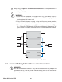
Dual Input (Parallel Units)
When there are two AC power sources, parallel units’ wiring procedures are as follows.
1
Follow !"#$#% to modify the UPS into dual input. Please note that only authorized Delta engineers or service personnel can modify single input/ dual input setup.
2
Please follow steps 1 | 5 stated in section Single Input (Single Unit).
3
Connect the main AC source/ bypass source/ output/ external battery cabinet cables
to the wiring terminal block (please refer to Figures 6-12~6-17/ 6-19).
4
Use the provided parallel cable to connect the parallel ports on the parallel units.
Please see Figure 5-1 for parallel port location.
39
5
Please refer to Chapter 5 : Communication Interfaces to set the parallel switch in
the ON or OFF position.
6
Ground the parallel UPSs.
WARNING:
1. When UPSs are paralleled, the length of each unit’s input cables/ output cables must be equal. This ensures that the parallel UPSs can equally share the
equipment loads in bypass mode.
@'*=
%+
otherwise, parallel functions will fail.
{ N
+
%
"^}_
2 or 3) through LCD. Otherwise, UPSs can not be started. If the symbol '!' ap"
#
="
AC Input
3Ø4W
Bypass Input
Parallel Port
UPS 1
AC Input
Second
Source
Parallel Cable
Main
Source
UPS Output
UPS Output
3Ø4W
Bypass Input
(for Bypass)
UPS 2
3Ø4W
LOAD
Parallel Port
Parallel Port
Parallel Cable
UPS Output
AC Input
Bypass Input
Parallel Port
UPS 4
(Figure 6-19: Parallel Units Dual Input Wiring Diagram)
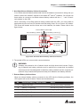
6.6
External Battery Cabinet Connection Precautions
WARNING:
You can connect loads to the UPS only after the batteries are fully charged. This
'*%
=ed when a power failure occurs.
Ultron HPH Series UPS
40
Chapter 6
y
Installation and Wiring
Battery
1. Charge Voltage
_ ;%>`^
N%>}^
2. Charge Current
_ >
20/ 30/ 40kVA
¼
1A
$
>
20kVA
¼
5A
30/ 40kVA
¼
9A
20kVA
¼
2A
30/ 40kVA
¼
5A
{ ">
{ J=N=>_}^>_}
~ :N
>_$~}^_${~|}^
NOTE:
1. You can adjust the charge current from 1A to the maximum. Each adjustment
level is 0.5A.
2. If you need to modify the charge current default setting and low battery shutdown default setting, please contact your local dealer or service personnel.
y
Only use the same type of batteries from the same supplier. Never use old, new and different Ah batteries at the same time.
y
The number of batteries must meet UPS requirements.
y
Do not connect the batteries in reverse.
y
y
y
y
Use the voltage meter to measure whether the total voltage, after the external battery cabinet connection, is around 12.5Vdc × the total number of batteries.
To extend battery backup time, you can connect several external battery cabinets to the
UPS.
When connecting a non-Delta external battery cabinet to the UPS, it is compulsory to install an appropriate non-fuse DC breaker and fast-acting fuses (when short-circuit occurs,
|
Please follow the table below to select appropriate battery fuses for different rating-power
UPSs.
41
Circuit Breaker
Rating Current (A)
Battery Cable
(mm²)
Battery Fuse (A)
20
63
10
63
30
100
25
100
40
125
25
125
The breaker must be a 4-pole non-fuse DC breaker with characteristics of 1-pole 250Vdc,
2-pole 500Vdc and 3-pole 750Vdc. Please follow Figure 6-20 or Figure 6-21 to install a
4-pole non-fuse DC breaker and fast-acting fuses between the UPS and the non-Delta external battery cabinet.
+
+
N
External
Battery
Cabinet
N
-
UPS
y
Rating Power
(kVA)
4-pole Non-fuse
DC Breaker
Fast-acting
Fuses
(Figure 6-20: A 4-pole Non-fuse DC Breaker and Fast-acting Fuses Installation I)
4-pole Non-fuse
DC Breaker
N
N
UPS
+
+
External
Battery
Cabinet
Fast-acting
Fuses
-
-
(Figure 6-21: A 4-pole Non-fuse DC Breaker and Fast-acting Fuses Installation II)
Ultron HPH Series UPS
42
Chapter 6
y
Installation and Wiring
Non-Delta External Battery Cabinet Connection
A non-Delta external battery cabinet shall include 40 batteries connected in string and you
should connect the cabinet’s neutral to the middle 20th and 21st batteries. You should use
three cables to connect a non-Delta external battery cabinet with the ‘+’, ‘-’ and ‘N’ terminals marked on the UPS.
When connecting a non-Delta external battery cabinet with the UPS, you must install an
appropriate 4-pole non-fuse DC breaker and fast-acting fuses. Do not use an AC breaker.
The closer the breaker and the fuses are to the batteries, the better. Please refer to the
=
External Battery Cabinet (N)
+)
External Battery Cabinet (
External Battery Cabinet (
External
Battery
Cabinet
-)
Fast-acting
Fuses
4-pole Non-fuse
DC Breaker
+ -
+ -
+ -
+ -
+ -
+ -
1
2
20
21
22
40
(Figure 6-22: Non-Delta External Battery Cabinet Connection)
y
The parallel UPSs can connect with common batteries.
WARNING:
A battery can present a risk of electric shock and high short-circuit current. Servic
%
+
service personnel knowledgeable in batteries, battery cabinets and the required precautions. Keep unauthorized personnel away from batteries and battery cabinets.
y
External Battery Cabinet Alarm
When an external battery cabinet connected to the UPS has the following problems, the
UPS system will sound an alarm. Please see the table below.
No.
External Battery Cabinet Status
Alarm
1
Battery Test Fail
Sounds once every 2 seconds.
2
Battery Low Warning
Sounds once every 0.5 second.
3
Battery Low Shutdown
Long beep (5 seconds)
4
Battery Over Charge
Sounds once every 2 seconds.
5
Battery Missing
Sounds once every 2 seconds.
43
Chapter 7 : Operation
7.1
7.2
Connecting the UPS with the Utility AC Power
1
Connect the UPS with an external battery cabinet, and switch the battery cabinet’s
switch/ breaker to the ON position.
2
Switch on the bypass input breaker and press the ON key ( ON ) to start the LCD. AfJX"=
==N<*
BYPASS ) will illuminate (yellow). For the position of each breaker,
LED indicator (
please refer to 3.5 Rear Panel.
3
Switch on the main input breaker and the utility AC power supplies power to the UPS.
Turn-on
Press the ON key (
the UPS.
7.3
ON
{|~
Turn-off
y
In online mode, press the OFF key ( OFF ) once and the LCD shows the following screen.
). The inverter will shut down, the buzzTo turn off the UPS, press the DOWN key (
er will sound once, and the system will transfer to bypass mode. At this time, the bypass
BYPASS ) illuminates (yellow).
LED indicator (
6+87'2:1
?
<(6 12
y
In battery mode, press the OFF key ( OFF ) once and the LCD shows the following
). The inverter will shut down,
screen. To turn off the UPS, press the DOWN key (
the buzzer will sound once, and the UPS will shutdown.
Ultron HPH Series UPS
44
Chapter 7
6+87'2:1
Operation
?
<(6 12
WARNING:
You can remove the UPS only after the screen on the LCD is off, the fans stop running, the utility AC power is shut off and the batteries are removed.
45
Chapter 8 : LCD Display and Settings
8.1
LCD Display Hierarchy
(Level 1)
(Level 1)
PARALLEL SCREEN
(Level 1)
MAIN SCREEN
ALARM/ FAULT
INFORMATION
(Level 2)
MAIN MENU
(Level 3)
(Level 3)
MAINTENANCE
MEASURE
(Level 4)
(Level 4)
MODEL NAME
MAINS
(Level 5)
(Level 5)
VPHASE(V)/ VLINE(V)/ FREQ(Hz)
SERIAL NUMBER
BYPASS
(Level 5)
(Level 5)
VPHASE(V)/ VLINE(V)/ FREQ(Hz)
FIRMWARE VERSION
INVERTER
(Level 5)
(Level 5)
VPHASE(V)/ VLINE(V)/ FREQ(Hz)
STATISTICS
OUTPUT
(Level 5)
VOLTAGE(V)/ CURRENT(A)/
CAPACITY(%)
(Level 5)
(Level 5)
VPHASE(V)/ VLINE(V)/ FREQ(Hz)
LOAD(%)/ KW/ KVA/ CURRENT(A)
PFC/ INV & SYSTEM
BATTERY
RUN TIME/ ON BAT COUNTS/
ON BYPASS COUNTS/
TOTAL OF EVENT LOG
EVENT LOG
(Level 5)
TEMPERATURE
EVENT LOG
(Level 5)
(Level 5)
REAR TIME CLOCK
AMB/ PFC/ INVERTER
DC BUS
DATE(Y-M-D)/ TIME(H-M-S)
(Level 5)
(Level 5)
CONTROL & TEST
BUS(+)/ BUS(-)
BATT TEST/ BEEP ENABLE
LANGUAGE SETUP
(Level 5)
(Figure 8-1: LCD Display Hierarchy)
LANGUAGE
NOTE:
1. Please refer to 3.2 Front Panel for information about the LCD and function keys.
2. All information shown in the LCD diagrams presented in Chapter 8 : LCD Display and Settings are for reference only. Actual readings depend on the operation of the UPS.
Ultron HPH Series UPS
46
Chapter 8
8.2
LCD Display and Settings
Main Screen
After initialization, the LCD will show current UPS status diagram as follows. The system
shows different screens depending on the status of the UPS. There are six statuses, and
each is called Main Screen. Please see below for further information.
The six statuses of the UPS shown in the LCD display are as follows.
1
When the screen above appears, it means that no power is supplied to the critical loads connected.
2
When the screen above appears, it means the bypass is supplying power to the critical loads.
3
When the screen above appears, it means that the UPS is in bypass mode. The main AC
source and the batteries are off. If the bypass AC source fails, the critical loads won’t be protected.
4
47
When the screen above appears, it means that the UPS is in normal mode.
5
When the screen above appears, it means that the UPS is in battery mode.
6
When the screen above appears, it means that the UPS is in manual bypass mode. Before
maintenance, do not forget to switch the UPS into manual bypass mode and cut off the main
AC source and batteries. During this mode, if the bypass AC source fails, the critical loads
won’t be protected.
8.3
Parallel Screen
When UPSs are paralleled, press either the function key (
Screen to enter into the Parallel Screen as follows.
,'
) or (
0,'
,19
21
y
ID: In parallel mode, this means the UPS’s ID No.
y
MID: Master UPS’s ID No. (In parallel mode, there is only one mater UPS).
y
INV: “
” means ‘CONNECTED’
y
ON: “
” means ‘INVERTER ON’
Ultron HPH Series UPS
48
) in a Main
Chapter 8
8.4
LCD Display and Settings
Main Menu
In a Main Screen, press the function key (
) to enter into the Main Menu shown below.
!0($685(
0$,17(1$1&(
y
MEASURE
Check the UPS’s mains, bypass, inverter, output, battery, temperature and DC BUS readings.
y
MAINTENANCE
X'*
=%
%
time clock, control & test, and language setup. User can set up the last two items.
49
8.5
Measure
Route: Main Screen ¼ Main Menu ¼ Measure
Use the function keys (
) and (
) to check the UPS’s mains, bypass, inverter,
output, battery, temperature and DC BUS readings. Please refer to the charts below.
0$,16
93+$6(9
9/,1(9
)5(4+]
5
6
7
'&%86
%86
%86
%<3$66
93+$6(9
9/,1(9
)5(4+]
5
6
7
7(03(5$785(
$0%
3)&
,19(57(5
7
%$77(5<
92/7$*(9
&855(17$
&$3$&,7<
7
287387
&855(17$
,19(57(5
5
93+$6(9
9/,1(9
)5(4+]
287387
93+$6(9
9/,1(9
)5(4+]
5
6
6
287387
/2$'
.:
.9$
Ultron HPH Series UPS
5
50
6
7
9
9
℃
℃
℃
5
)/2$7
6
7
Chapter 8
8.6
LCD Display and Settings
Maintenance
Route: Main Screen ¼ Main Menu ¼ Maintenance
Use the function keys (
) and (
) to check the UPS’s model name, serial num=%
%
User can set up the last two items. Please see below for detailed information.
y
Model Name
Route: Main Screen ¼ Main Menu ¼ Maintenance ¼ 2.1 Model Name
02'(/1$0(
;;;;;;;;;;;;;;;
The screen above shows the UPS’s model name.
y
Serial Number
Route: Main Screen ¼ Main Menu ¼ Maintenance ¼ 2.2 Serial Number
6(5,$/180%(5
;;;;;;;;;;;;;;;
The screen above shows the UPS’s serial number.
y
Firmware Version
Route: Main Screen ¼ Main Menu ¼ Maintenance ¼ 2.3 Firmware Version
),50:$5(9(56,21
3)&
,196<67(0
:%=*;X<:K=%
51
y
Statistics
Route: Main Screen ¼ Main Menu ¼ Maintenance ¼ 2.4 Statistics
67$7,67,&6
5817,0(
21%$7&28176
21%<3$66&28176
67$7,67,&6
727$/2)(9(17/2*
''++0066
1. RUN TIME (DD HH: MM: SS): The UPS’s total running time.
2. ON BAT COUNTS: How many times the UPS runs in battery mode.
3. ON BYPASS COUNTS: How many times the UPS runs in bypass mode.
4. TOTAL OF EVENT LOG: The UPS’s total number of event log.
y
Event Log
Route: Main Screen ¼ Main Menu ¼ Maintenance ¼ 2.5 Event Log
(9(17/2*
(9(17/2*
The screen above shows event No., event date, time, and event descriptions. Use the
function keys (
) and (
) to view other events. The event number means the
event code. The greater the event number, the newer the event. Old events will be overwritten when the total number of events exceeds storage capacity (up to 200 entries can
be saved).
y
Real Time Clock
Route: Main Screen ¼ Main Menu ¼ Maintenance ¼ 2.6 Real Time Clock
5($/7,0(&/2&.
'$7(<0'
7,0(+06
The screen above shows date and time.
Ultron HPH Series UPS
52
Chapter 8
y
LCD Display and Settings
Control & Test
Route: Main Screen ¼ Main Menu ¼ Maintenance ¼ 2.7 Control & Test
&21752/7(67
%$777(67
%((3(1$%/(
6(&
21
1. BATT TEST: Enable or disable battery test. Three are three choices, ABORT, DEEP or
10 SEC.
2. BEEP ENABLE: Enable or disable buzzer.
y
Language Setup
Route: Main Screen ¼ Main Menu ¼ Maintenance ¼ 2.8 Language Setup
/$1*8$*(6(783
/$1*8$*(
(1*/,6+
You can change the display language. The default setting is ENGLISH.
53
Chapter 9 : Optional Accessories
There are several optional accessories available for this HPH series UPS. Please refer to the table below for the optional accessories and their descriptions.
No.
Item
Function
1
Dust Filter
Prevents dust from entering into the UPS to ensure UPS reliability and to prolong product life.
2
EnviroProbe
Monitors temperature, humidity and other conditions in a room
environment. The EnvioProbe should work with either an SNMP
card or an EMS2000.
3
SNMP Card (IPv4 or
IPv6)
Monitors and controls the status of the UPS via a network system.
4
Relay I/O Card
Increases the quantity of dry contacts.
5
ModBus Card
Lets the UPS have ModBus communication function.
6
Mini TVSS Card
Lets the UPS have surge protection function.
7
Mini USB Card
Lets the UPS have USB communication function.
8
Mini SNMP Card
Monitors and controls the status of the UPS via a network system.
9
Mini Relay I/O Card
Increases the quantity of dry contacts.
10
Mini ModBus Card
Lets the UPS have ModBus communication function.
REFERENCE:
1. For detailed installation and operation of any accessory mentioned above, please refer to
the Quick Guide, User Guide, or Installation & Operation Guide included in the package of the relevant optional accessory.
2. If you want to buy any accessory mentioned above, please contact your local dealer or
customer service.
Ultron HPH Series UPS
54
Chapter 10
Maintenance
Chapter 10 : Maintenance
y
UPS
_ '*X
>
'*
#=
into the UPS to avoid overheating. If necessary, use an air-gun to clean the slits and openings
to prevent any object from blocking or covering these areas.
'*
>
'*%
>
1) Whether the UPS, LEDs, and alarm function are operating normally.
2) Whether the UPS works in bypass mode (normally, the UPS will work in normal mode). If
yes, check if any error, overload, internal fault, etc. occurs.
3) Whether battery voltage is normal. If the battery voltage is too high or too low, find the root
cause.
y
Battery
The HPH series UPS uses sealed lead-acid batteries. The battery life depends on the temperature, the usage, and the charging/ discharging frequency. High temperature environments and high
charging/ discharging frequency will quickly shorten the battery life. Please follow the suggestions
below to ensure a normal battery lifetime.
_ =_X|X
2. When the UPS needs to be stored for an extended period of time, the batteries must be recharged
once every three months and the charging time must not be less than 24 hours each time.
y
Fan
Higher temperatures shorten fan life. When the UPS is running, please check if all fans work normally and make sure if the ventilation air can move freely around and through the UPS. If not, replace the fans.
NOTE:
Please ask your local dealer or customer service for more maintenance information. Do not
perform maintenance if you are not trained for it.
55
Chapter 11 : Troubleshooting
When you see the following problems appear on the LCD, please follow the solutions shown below.
No. Alarm Message
Possible Cause
Solution
1
SHORT CIRCUIT
Output has a short circuit issue.
Contact service personnel.
2
INVERTER FAIL
Inverter is damaged.
Contact service personnel.
3
OVER TEMPERATURE
The UPS temperature is too high.
1. Choose a well-ventilated area.
2. Decrease some loads.
3. Check if fans run normally.
~X
4
PFC AMBIENT
OVER TEMP. FAIL
The UPS temperature is too high.
1. Choose a well-ventilated area.
2. Decrease some loads.
3. Check if fans run normally.
~X
5
INVERTER SCR
OPEN
Inverter SCR driver is abnormal.
Contact service personnel.
6
BYPASS SCR
OPEN
Bypass SCR driver is abnormal.
Contact service personnel.
7
OVERLOAD
The UPS is overloaded.
Remove some unnecessary loads
to let total load capacity below
YZ
8
FAN FAIL
Fans are damaged or stuck.
Contact service personnel.
9
BYPASS SCR
SHORT FAIL
1. Bypass SCR driver is damaged.
Contact service personnel.
INPUT SCR
SHORT FAIL
1. Input SCR driver is damaged.
11
OUTPUT FUSE
FAIL
Output fuse is broken.
Contact service personnel.
12
AUX POWER FAIL
Auxiliary power is damaged.
Contact service personnel.
13
INDUSTRY PROTECT
In industrial mode, output has an
over current issue.
Check if output is normal.
10
Ultron HPH Series UPS
2. Bypass SCR has a short circuit
issue.
Contact service personnel.
2. Input SCR has a short circuit
issue.
56
Chapter 11
No. Alarm Message
Possible Cause
Solution
Troubleshooting
14
BATTERY REVERSED
Batteries are connected in reverse.
Please check the batteries’ polarity.
15
INPUT PHASE
SEQUENCE FAIL
Input phase sequence is wrong.
Check input phase sequence.
16
INVERTER SOFT
START FAIL
1. Inverter detection is abnormal.
Contact service personnel.
17
INNER COMMUNICATION FAIL
Inner communication cable is not
well connected.
Contact service personnel.
18
PFC SUPERVISOR FAIL
PFC CPU is damaged.
Contact service personnel.
19
DC BUS HIGH
SHUTDOWN
1. Output has abnormalities.
Contact service personnel.
DC BUS LOW
SHUTDOWN
1. Output has abnormalities.
21
INPUT FUSE FAIL
Input fuse is broken.
Contact service personnel.
22
INVERTER SUPERVISOR FAIL
Inverter CPU is damaged.
Contact service personnel.
23
PFC SOFT START
FAIL
1.
Contact service personnel.
24
BYPASS PHASE
SEQUENCE FAIL
Bypass phase sequence is wrong.
Please check bypass phase sequence.
25
NTC OPEN FAIL
1. NTC is not connected well.
2. NTC line is broken.
Contact service personnel.
26
INVERTER OUTPUT SCR SHORT
1. Inverter SCR driver is abnormal.
Contact service personnel.
BATTERY LOW
SHUTDOWN
Battery voltage is low.
20
27
2. Inverter’s driver is damaged.
2. The UPS has internal faults.
Contact service personnel.
2. The UPS has internal faults.
2. Driver is damaged.
2. Inverter SCR is damaged.
Charge the batteries.
NOTE:
If all possible causes are eliminated but the alarm still appears, please contact your local
dealer or customer service.
57
Model
Power Rating
HPH-20K
HPH-30K
HPH-40K
20kVA/20KW
30kVA/30KW
40kVA/40KW
Waveform
Sine Wave
Nominal Voltage
}!{}{}!~}}~}!~_
Voltage Range
{}}|~``^_}}Z
Frequency
50/60 Hz
Input
Frequency Range
Input Current
~}|`}\
36.8A
Power Factor
}!{}{}!~}}{~}!~_
Power Factor
Unity
Voltage Regulation
_Z
Voltage Harmonic
Distortion
_Z^
Overload Capability
73A
}YY^
Voltage
Output
55A
_}Z>
_}Z|_Z>_}
_Z|_}Z>_
_}Z>_
Output Frequency
50/60 Hz ± 0.05 Hz
Cress Factor
{>_
Online Mode
'YZ
ECO Mode
'YYZ
Type
SMF/ VRLA
K
Battery Voltage
Battery
Maximum
Charge Current
± 240 Vdc
5A
LED & LCD
Ultron HPH Series UPS
9A
Float charge 272 ± 2 Vdc
Boost charge 280 ± 2 Vdc
Charge Voltage
Audible Noise
9A
N
}N
}N
LED indicators and Multi-language LCD display
58
Appendix 1
Model
Communication Interfaces
HPH-20K
HPH-30K
Yes
Dimensions
(W x D x H)
Weight
380 x 800 x 800 mm
66.5 Kg
86.2 Kg
Operating
Temperature
Environment
HPH-40K
SMART Slot x 1, MINI Slot x 1, Parallel Port x 2,
RS232 Port x 1, REPO Port x 1,
Charger Detection Port x 1, Input Dry Contact x 2,
Output Dry Contact x 6
Manual Bypass Switch
Physical
}|~}X
Ambient Storage
Temperature
}|}X
Relative Humidity
Z|YZ^
NOTE:
1. Please refer to the rating label for the safety rating.
=
59
86.5 Kg
Appendix 2 : Warranty
Seller warrants this product, if used in accordance with all applicable instructions, to be free from original defects in material and workmanship within the warranty period. If the product has any failure problem within the warranty period, Seller will repair or replace the product at its sole discretion according
to the failure situation.
This warranty does not apply to normal wear or to damage resulting from improper installation, opera
^
=
=
also expressly excludes all incidental and consequential damages.
Maintenance service for a fee is provided for any damage out of the warranty period. If any maintenance is required, please directly contact the supplier or Seller.
WARNING:
The individual user should take care to determine prior to use whether the environment and
the load characteristic are suitable, adequate or safe for the installation and the usage of this
product. The User Manual must be carefully followed. Seller makes no representation or war
Ultron HPH Series UPS
60
5012332300