1
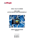
INTERFACE & DESIGN REFERENCE KIT
For Use with eMagin Rev2 SVGA+, SVGA 3D, and OLED-XL OLED Microdisplays
USER’S MANUAL
DRAFT III
For part numbers:
Monocular Interface & Design Reference Kit
Binocular Interface & Design Reference Kit
EMA-200002
EMA-200003
TABLE OF CONTENTS
1.
INTRODUCTION .................................................................................................................................. 1
2.
FEATURES .......................................................................................................................................... 1
2.1.
Standard Built-in Software ........................................................................................................... 1
2.2.
Software Features ....................................................................................................................... 1
2.3.
Features Comparison Tables ...................................................................................................... 2
3.
SYSTEM REQUIREMENTS & SPECIFICATIONS.............................................................................. 2
3.1.
System Requirements ................................................................................................................. 2
3.2.
Stereovision 3D Requirements .................................................................................................... 2
3.3.
PC Interface Kit Parameters ........................................................................................................ 2
3.4.
Mechanical Dimensions & Features (Dimensions in Inches) ...................................................... 3
4.
PC INTERFACE KIT COMPONENTS ................................................................................................. 4
4.1.
Monocular Interface & Design Reference Kit .............................................................................. 4
5.
INTERFACE CONNECTIONS & SETUP............................................................................................. 4
5.1.
Connect Display to Cable Assembly ........................................................................................... 4
5.2.
Setup PC for Proper Video Output .............................................................................................. 5
5.3.
Power Up ..................................................................................................................................... 5
5.4.
Power Down ................................................................................................................................ 6
5.5.
High Brightness Mode ................................................................................................................. 6
6.
USING THE INTERFACE & DESIGN REFERENCE KIT SOFTWARE.............................................. 6
6.1.
Serial Interface Command Set..................................................................................................... 6
6.1.1.
6.1.2.
6.2.
6.2.1.
6.3.
6.3.1.
Hardware Protocol..................................................................................................................................7
eMagin Software Command Set.............................................................................................................8
Using Hyperterminal With the Interface & Design Reference Kit ................................................ 8
ASCII Table of Commands...................................................................................................................10
Uploading New Firmware Versions to the Interface & Design Reference Kit ........................... 11
Using the Firmware Download Utility....................................................................................................11
7.
ADVANCED USER INFORMATION.................................................................................................. 12
7.1.
Microcontroller ........................................................................................................................... 12
7.2.
I2C bus ....................................................................................................................................... 12
8.
REVISION HISTORY ......................................................................................................................... 12
DRAFT III
Interface & Design Reference Kit User’s Manual
i
List of Tables
TABLE 2-1: FUNCTIONALITY COMPARISION BETWEEN SVGA+ AND SVGA 3D MICRODISPLAYS .......2
TABLE 6-1 COMMAND SET LIST FOR ADDRESSING THE MICRODISPLAY ..................................................8
TABLE 6-2 TABLE OF ASCII CHARACTER CODES............................................................................................10
List of Figures
Figure 3-1 Interface & Design Reference Kit Dimensions (inches).............................................. 3
Figure 3-2 Interface & Design Reference Kit Features Layout ..................................................... 3
Figure 5-1 Interface Connection Diagram .................................................................................... 4
Figure 5-2 Connection Orientation Illustration ............................................................................ 5
Figure 6-1 Interface & Design Reference Kit Software Utility ...................................................... 7
Figure 6-2 Example microdisplay register value write using included software........................... 8
Figure 6-3 Example microdisplay register value write using Hyperterminal................................ 9
Figure 6-4 Firmware download utility ......................................................................................... 11
DRAFT III
Interface & Design Reference Kit User’s Manual
ii
1. INTRODUCTION
The Interface & Design Reference Kit, compatible with both SVGA+ and SVGA 3D Series
Microdisplays, provides the user with a highly compact, portable way of operating an eMagin
OLED Microdisplay with a variety of video inputs. This product was designed to deliver a
complete tool for developers to evaluate and integrate eMagin microdisplays into new products.
The Interface & Design Reference Kit is compatible both with analog RGB and composite
(NTSC, SMPTE-170, PAL) sources. The included software package and cables provides access to
the microdisplay’s on-board register settings from any Windows-based PC through a serial port.
When used with an SVGA 3D OLED Microdisplay, the binocular Interface & Design Reference
Kit features automatic stereovision signal to allow the user easy development of stereoscopic 3D
applications.
2. FEATURES
PC Analog Monitor Video Interface (VESA Display Monitor Timing Standard compliant)
Composite interface cable for connection to SMPTE-170, NTSC, PAL sources
RS-232 (serial) cable allows access to microdisplay registers
Supporting Software (Windows)
ON/OFF power switch
Push-button brightness control
Push-button image scan direction control
VGA monitor cable
USB Power Cable, length 2 feet (NOTE: Provided cable is compatible with USB 1.0 and 2.0
USB ports, but may not be compatible with all types of PCs. In some cases an external 5V DC
power supply may be necessary)
Regulated AC/DC adapter (optional)
Auto detection of stereovision input signal for SVGA 3D OLED Microdisplays (binocular
configuration only)
Compatibility with eMagin SVGA+ and SVGA 3D Microdisplays
2.1. Standard Built-in Software
The presence of frame sequential stereovision input is automatically detected and set up when
the display is turned on. Switching the power off and then on will initiate detection of
stereovision signals on binocular kits, if the incoming signal is changed during operation.
Automatic determination of incoming frame rate and matching
Image orientation adjustment with single button push makes integration into various systems
easier.
Luminance can be stepped in 255 of the luminance range steps with momentary pushing of
the up/down luminance button. If the luminance control button is held down in the up or down
position for more than 1 second, rapid scanning through the luminance range will initiate up
or down to permit fast changing of display luminance.
Comes ready with a high brightness mode accessible through a special button sequence.
2.2. Software Features
DRAFT III
Read/write capabilities allow adjustments of microdisplay register settings to fine-tune image
characteristics
Software slide bar control over the cathode voltage (Vcommon) input in 255 equal steps
Software slide bar control over the microdisplay’s brightness in 255 equal steps
Download and install new firmware files into your Interface & Design Reference Kit for easy
upgrades and expanded functionality
Interface & Design Reference Kit User’s Manual
1
Ability to read the ambient temperature measured at the microdisplay’s location
Save feature stores custom register settings for convenience
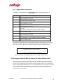
2.3. Features Comparison Tables
TABLE 2-1: FUNCTIONALITY COMPARISION BETWEEN SVGA+ AND SVGA 3D
MICRODISPLAYS
Capability
Ability to interface display with a PC
Access to microdisplay registers (with included software
and serial cable)
Button-activated brightness control on unit
Button-activated rotation control on unit
Display SVGA (800 x 600) image at 60Hz
Display SVGA (800 x 600) Stereovision 3D image
(binocular)*
Display NTSC, PAL, or RS-170 image
SVGA+
Yes
Yes
SVGA 3D
Yes
Yes
Yes
Yes
Yes
No
Yes
Yes
Yes
Yes
Yes
No
3. SYSTEM REQUIREMENTS & SPECIFICATIONS
3.1. System Requirements
For analog RGB inputs: A PC capable of producing a VGA or SVGA signal
For composite inputs: An NTSC, PAL, or SMPTE-170 video source
Support software requires a Windows PC with an RS-232 serial port
3.2. Stereovision 3D Requirements
Binocular Interface & Design Reference Kit
A video graphics adapter capable of supporting a Stereovision 3D video signal. Additional
drivers may need to be downloaded from the manufacturer’s website.
Two SVGA 3D OLED Color Microdisplays (EMA-100052). Stereovision is not compatible
with SVGA+ OLED Microdisplays
3.3. PC Interface Kit Parameters
Power
Weight
DRAFT III
Monocular = 300 to 500 mW
Binocular = 600 to 850 mW
(Depending on brightness setting and images)
4.0 oz (interface module & cable)
Interface & Design Reference Kit User’s Manual
2
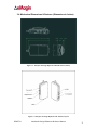
3.4. Mechanical Dimensions & Features (Dimensions in Inches)
Figure 3-1 Interface & Design Reference Kit Dimensions (inches)
Figure 3-2 Interface & Design Reference Kit Features Layout
DRAFT III
Interface & Design Reference Kit User’s Manual
3
4. INTERFACE & DESIGN REFERENCE KIT
COMPONENTS
4.1. Monocular Interface & Design Reference Kit
Part Number
EMA-200002
EMA-100153
A01-500004-01
591-02111-01
591-03014-01
A01-500205-00
C01-500317-00
Item Description
Monocular Interface & Design Reference Kit
Monocular OLED Cable Assembly
OLED Display Interface Module
VGA Cable, 1 foot
USB to Power Input Cable, 2 foot
RS232-to-I2C Cable
Composite Input Cable
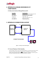
5. INTERFACE CONNECTIONS & SETUP
VGA
CONNECTOR
VGA
CONNECTOR
PERSONAL
COMPUTER
INTERFACE
MODULE
USB
CONNECTOR
POWER INPUT
CONNECTOR
CONNECTION DIAGRAM
J2
CABLE
TERMINATION
PCB
SVGA-3D
OLED
DISPLAY
Figure 5-1 Interface Connection Diagram
5.1. Connect Display to Cable Assembly
The microdisplay connects to the Cable Termination Board via a 30-pin board-to-board connector.
The present version of the connector is NOT keyed so it is important to correctly orient the
display. Refer to the picture below for the proper orientation. The display is seen face up above
the Cable Termination board and is in correct positioning for connection.
DRAFT III
Interface & Design Reference Kit User’s Manual
4
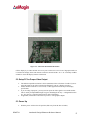
Figure 5-2 Connection Orientation Illustration
Lift the display by its sides and take care not to press on the active area or leave fingerprint marks on
it. Position the display board such that the connectors match and the “J2” is in a normally readable
orientation. Insert the display into the Cable board.
5.2. Setup PC for Proper Video Output
The default compatible resolution is SVGA (800x600) with a refresh rate of 60 Hz. If you are
using this input set the video resolution for 800x600 in your PC’s display properties.
Ensure that the refresh rate to set to 60 Hz, or other supported refresh rate per the display
specification.
If you are using a laptop PC, you may need to export the video signal to an external monitor.
This is usually accomplished through a keypress including the Fn key + a designated function
key. See your PC’s operation instructions for more information.
If applicable, enable Stereovision 3D on your PC’s video graphics adapter.
5.3. Power Up
DRAFT III
Slide the power switch to the ON position (slide away from the other switches).
Interface & Design Reference Kit User’s Manual
5
Note: Power supplies with voltage spikes can damage the display. If using any input other than
the USB to power connection supplied with the system or the optional regulated AC/DC adapter,
use caution to make sure the power is from a low noise voltage source. Use only 5V DC supplies
with no more than a maximum +/-0.25V variation.
5.4. Power Down
Slide the power switch to the OFF position (slide toward the other switches).
5.5. High Brightness Mode
Each Interface & Design Reference Kit is preinstalled with the capability to drive a display in high
bias mode. In order to access the high bias ranges you need to activate this mode by
simultaneously pressing the image orientation button and the brightness down button (shown with
a minus (-) sign).
eMagin strongly recommends that you drive the microdisplay at the minimum luminance
necessary for your application. This will extend the lifetime of the display to its maximum
possible lifetime. As OLED microdisplays are emissive devices, driving the microdisplay at high
bias levels will decrease its overall lifetime.
6. USING THE INTERFACE & DESIGN REFERENCE KIT
SOFTWARE
The Interface & Design Reference Kit includes a support software suite with the following
functionality.
Perform software microdisplay brightness adjustments through 255 equal steps
Perform software adjustments of the Vcommon input to the microdisplay through 255 equal
steps
Read the ambient temperature at the microdisplay site
Perform reads and writes to the Interface & Design Reference Kit EEPROM
Download and install new versions of the Interface & Design Reference Kit to update or
provide new functionality using an RS-232 connection
Read/write register values to the microdisplay to control various characteristics (see your
microdisplay’s User Specification for more information)
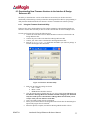
6.1. Serial Interface Command Set
The Interface & Design Reference Kit can be controlled by sending commands and data using the
included RS-232 cable. The software package includes a file called DRK_SW.exe developed for
this purpose.
Using the eMagin Interface & Design Reference Kit Software
1.
2.
3.
4.
5.
DRAFT III
Connect the serial cable to the PC (Port 1) and to the RS232 connector on the Interface &
Reference Design Kit
Connect the power cable to the Interface & Reference Design Kit
Connect the video source to the Interface & Reference Design Kit
Turn on the Interface & Reference Design Kit
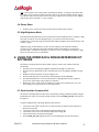
Start the DRK_SW.exe application and a screen should appear like that shown below:
Interface & Design Reference Kit User’s Manual
6
Figure 6-1 Interface & Design Reference Kit Software Utility
6.
7.
8.
The application communicates with the PIC on the Interface & Design Reference Kit and
reads the initial status of the “Brightness,” “Vcathode,” and “OLED Registers” outputs.
The read/write buttons shown in the “OLED Registers” panel will read/write the register
settings in their corresponding boxes from/to the OLED microdisplay.
The read/write buttons displayed in the EEProm panel will read/write the settings displayed in
the register boxes from/to the Interface & Design Reference Kit’s EEProm. This will allow
you to save custom settings you wish to upload to the microdisplay when its power is cycled.
Direct control of the Interface & Design Reference Kit can also be implemented into a customer
specific application using the following hardware protocol and command set.
6.1.1.
DRAFT III
Hardware Protocol
bit, no parity
9600 baud
No hardware handshake
Interface & Design Reference Kit User’s Manual
7
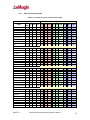
6.1.2.
eMagin Software Command Set
TABLE 6-1 COMMAND SET LIST FOR ADDRESSING THE MICRODISPLAY
REGISTERS
Command
C
R
G
D
W
T
U
S
V
Description
Adjust the COMMON (Cathode) voltage
Usage: CX where X = 0 to 255
Read all 27 Microdisplay Registers.
Usage: R Returns 27 register values
Send a register address
Usage: GX where X = 0 to 27
Send a data value to the Interface & Design Reference Kit
Usage: DX where X = 0 to 255
Write a register
Usage: W
Note: The W command is preceded by a GX DY command
Read the temperature sensor value
Usage: T Returns a value
Adjust the microdisplay brightness
Usage: UX where X = 0 to 255
Returns the Brightness and COMMON (Cathode) level values
Usage: S Returns two values, brightness first then COMMON
Returns the firmware version number.
Usage: V Returns a value
Note: The commands and values are typically generated from a control program. The values are
sent in binary format to the Interface & Design Reference Kit microcontroller, which will process
these natively in binary. Below is an example write instance using the provided software:
In order to write the decimal value 81 to register 3, the following
commands need to be issued: G3D81W
No space is required between the commands
Figure 6-2 Example microdisplay register value write using included software
6.2. Using Hyperterminal With the Interface & Design Reference Kit
If you will use Hyperterminal to control the Interface & Design Reference Kit please note that
Hyperterminal converts all input data to ASCII characters. Therefore, the X value mentioned in
the table above needs first to be converted to its ASCII equivalent in order to be recognized by the
Interface & Design Reference Kit firmware. Received information will also be displayed as ASCII
code. An ASCII to decimal (or hexadecimal) conversion must be performed to read the correct
values sent via the serial interface. We have provided an example write instance and ASCII
character table for your reference.
DRAFT III
Interface & Design Reference Kit User’s Manual
8
To write the decimal value 81 to register 3, the following commands
need to be issued:
G CTRL-C D Q W
Ctrl+C (pressing the Ctrl and C key simultaneously) is the ASCII
equivalent of decimal 3
Note: No space is required between the commands. The spacing above
is for clarity only.
Figure 6-3 Example microdisplay register value write using Hyperterminal
DRAFT III
Interface & Design Reference Kit User’s Manual
9
6.2.1.
ASCII Table of Commands
TABLE 6-2 TABLE OF ASCII CHARACTER CODES
Non-Printing Characters
Printing Characters
Ctrl
Name
Dec Hex Char Dec Hex Char Dec Hex Char Dec Hex
char
null
ctrl-@ 0 00 NUL 32 20 Space 64 40 @
96 60
start of heading ctrl-A 1 01 SOH 33 21
!
65 41 A
97 61
start of text
ctrl-B 2 02 STX 34 22
"
66 42
B
98 62
end of text
ctrl-C 3 03 ETX 35 23
#
67 43
C
99 63
end of xmit
ctrl-D 4 04 EOT 36 24
$
68 44 D
100 64
enquiry
ctrl-E 5 05 ENQ 37 25
%
69 45
E
101 65
acknowledge
ctrl-F 6 06 ACK 38 26
&
70 46
F
102 66
bell
ctrl-G 7 07 BEL 39 27
'
71 47 G
103 67
backspace
horizontal tab
line feed
vertical tab
form feed
carriage feed
shift out
shift in
Char
`
a
b
c
d
e
f
g
ctrl-H
ctrl-I
ctrl-J
ctrl-K
ctrl-L
ctrl-M
ctrl-N
ctrl-O
8
9
10
11
12
13
14
15
08
09
0A
0B
0C
0D
0E
0F
BS
HT
LF
VT
FF
CR
SO
SI
40
41
42
43
44
45
46
47
28
29
2A
2B
2C
2D
2E
2F
(
)
*
+
,
.
/
72
73
74
75
76
77
78
79
48
49
4A
4B
4C
4D
4E
4F
H
I
J
K
L
M
N
O
104
105
106
107
108
109
110
111
68
69
6A
6B
6C
6D
6E
6F
h
i
j
k
l
m
n
o
data line escape ctrl-P
device control 1 ctrl-Q
device control 2 ctrl-R
device control 3 ctrl-S
device control 4 ctrl-T
neg acknowledge ctrl-U
synchronous idel ctrl-V
end of xmit block ctrl-W
16
17
18
19
20
21
22
23
10
11
12
13
14
15
16
17
DLE
DC1
DC2
DC3
DC4
NAK
SYN
ETB
48
49
50
51
52
53
54
55
30
31
32
33
34
35
36
37
0
1
2
3
4
5
6
7
80
81
82
83
84
85
86
87
50
51
52
53
54
55
56
57
P
Q
R
S
T
U
V
W
112
113
114
115
116
117
118
119
70
71
72
73
74
75
76
77
p
q
r
s
t
u
v
w
cancel
ctrl-X 24 18 CAN
end of medium ctrl-Y 25 19 EM
substitute
ctrl-Z 26 1A SUB
escape
ctrl-[ 27 1B ESC
file separator
ctrl-\ 28 1C FS
group separator ctrl-] 29 1D GS
record separator ctrl-^ 30 1E RS
unit separator
ctrl-_ 31 1F US
56
57
58
59
60
61
62
63
38
39
3A
3B
3C
3D
3E
3F
8
9
:
;
<
=
>
?
88
89
90
91
92
93
94
95
58
59
5A
5B
5C
5D
5E
5F
X
Y
Z
[
\
]
^
_
120
121
122
123
124
125
126
127
78
79
7A
7B
7C
7D
7E
7F
x
y
z
{
|
}
~
DEL
DRAFT III
Interface & Design Reference Kit User’s Manual
10
6.3. Downloading New Firmware Versions to the Interface & Design
Reference Kit
The ability to download new versions of the firmware ensures that you will have the latest
functionality without having to send your Interface & Design Reference Kit for reprogramming. A
utility that downloads and installs new firmware versions is included in the software package.
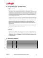
6.3.1.
Using the Firmware Download Utility
Firmware files can be downloaded as hex files. Before attempting to download and install new
firmware versions make sure that you have received a firmware hex file from an eMagin source.
To load your firmware files, follow the following steps:
1. Connect the serial cable to the PC and to the RS232 connector on the Interface &
Design Reference Kit.
2. Connect the power cable to the Interface & Design Reference Kit.
3. Connect your video source to the Interface & Design Reference Kit.
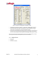
4. Start the PICdownloader.exe application included in your software package. A
window should appear like that below:
Figure 6-4 Firmware download utility
5.
6.
7.
8.
9.
DRAFT III
Make sure the following settings are shown
a. Port = COM1
b. Baud = 19200
c. EEPROM box should be checked
Click the Search button to find the hex file you wish to install. Note: The power on
the Interface & Design Reference should be off while setting up your download.
Only turn on the power to the Interface & Design Reference Kit when you are
ready to write your new firmware to the PIC.
Once successfully found, click the write button.
When you turn on the Interface & Design Reference Kit the hex file should begin to
upload. The progress bar will turn blue.
When the upload is complete, the Interface & Design Reference Kit will run.
Interface & Design Reference Kit User’s Manual
11
7. ADVANCED USER INFORMATION
7.1. Microcontroller
The Interface & Design Reference Kit circuit board utilizes a Microchip PIC16F876
microcontroller. This is a CMOS Flash microcontroller in a 28 pin package. Provisions are on the
circuit board for in circuit reprogramming but are not accessible without opening the case. When
using the internal programming connector VCC to the microcontroller is isolated from the rest of
the board by removing the jumper between pins 1 and 2 of J3. Please refer to the Microchip
PIC16F87X datasheet available from Microchip Technology Inc. for additional information about
the microcontroller and programming.
The main function of the microcontroller is to communicate with the OLED display and the digital
pot that controls the brightness of the display. The microcontroller also monitors the 3D Flipflop
to determine whether or not a Stereovision 3D signal is present. All communication is over the
internal I2C bus and the microcontroller acts as the bus master. On power up the registers of the
OLED are initialized with the default settings programmed into the microcontroller. After
initialization the microcontroller scans the pushbuttons for user input and monitors the 3D
Flipflop. The microcontroller enters the 3D mode only if a 3D signal is present and a second
OLED is detected.
If one of the Brightness pushbuttons is pushed the microcontroller transmits a new numeric value
to the digital pot to change the brightness voltage. This new value is then stored in non-volatile
memory so this value will be used on the next power-up.
7.2. I2C bus
The microcontroller is the bus master and communication occurs at the standard 100KHz clock
rate. The microcontroller, the OLED and the digital pot all operate from 3.3VDC so the I2C bus
must also operate using 3.3V logic levels. The maximum speed allowed for I2C bus
communication is 400KHz. The digital pot is a Analog Devices AD5243-10 and answers to I2C
bus address 5Eh. Please refer to the Philips I2C bus specification available on the Philips website
for detailed information.
8. REVISION HISTORY
Revision Level
DRAFT III
Date
Description
Interface & Design Reference Kit User’s Manual
12