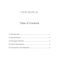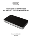
1
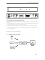
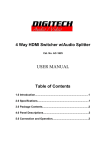
USER MANUAL Table of Contents 1.0 Introduction..........................................................................1 2.0 Specifications…………………………………….………..……1 3.0 Package Contents………………………………………….…..2 4.0 Panel Descriptions…………………………………….…….…2 5.0 Connection and Operation..................................................3 DVI + Audio to HDMI Converter DVI + Audio to HDMI Converter Dear Customer Thanks for your purchase of the DVI Audio to HDMI Converter. For optimum performance and safety, please read these instructions carefully before connecting, operating or adjusting this product. Please keep this manual for future reference. 1.0 INTRODUCTION This converter is designed to make your A/V equipment more comfortable, more productive and less expensive. It converts a digital DVI signal and toslink audio and digital audio input to an HDMI format allowing the viewing or switching of a digital AV signal on an HDMI system. The DVI+Audio to HDMI Converter is a unique device that combines digital video (DVI) and digital audio into HDMI to seamlessly integrate into the modern home theaters. This product not only meets the ideal image of the HDTV but also meets the need of the enthusiasts’ requirement for audio, because it transmits the audio signal by toslink audio and digital audio. This DVI+Audio to HDMI Converter offers solutions for noise, space and security concerns, data center control, information-distribution, conference-room presentation, school and corporate training environments. 1.1 FEATURES This Converter has many features that enable it to perform in a superior manner. Among those features you will find: Supports highest video resolution 1080p. Supports 225MHz/2.25Gbps per channel (6.75Gbps all channel) bandwidth. Supports 12bit per channel (36bit all channel) deep color. Toslink Audio and Digital Audio input/output Encodes digital audio onto the video signal for HDMI™ video and audio Allows you to connect computers or other sources with DVI output and SPDIF to an HDMI display Supports uncompressed audio such as LPCM Supports compressed audio such as DTS Digital, Dolby Digital(including DTS-HD and Dolby True HD) 2.0 SPECIFICATIONS Signal Inputs/Output Input DDC Signal Input Video Output Video 5 volts p-p (TTL) DVI 1.1v HDMI 1 DVI + Audio to HDMI Converter Connector HDMI Connector DVI Connector Audio Connector Operating Frequency Vertical Frequency Range Video Amplifier Bandwidth Resolutions(HDTV) Interlaced(50&60Hz) Progressive(50&60Hz) Mechanical Size(L-W-H) Weight (Net) Warranty Limited Warranty Environmental Operating Temperature Operating Humidity Storage Temperature Storage Humidity Power Requirement External Power Supply Power Consumption Regulatory Approvals Converter Unit Power Supply Accessories Adapter AC Power Adapter User Manual type A (19 pin) female DVI-I (29 pin) female (digital only) Toslink Audio and Digital Audio 50/60Hz 2.25Gbps/225MHz 480i,576i,1080i 480p,576p,720p,1080p 87.5×67.5×25.5mm 260g 1 Year Parts and Labor 0 ℃ to +70℃ 10% to 85 % RH (no condensation) -10℃ to +80℃ 5% to 90 % RH (no condensation) 5V DC@2A 5 watts (max) FCC,CE,UL UL,CE,FCC US standard, UK standard and so on English Version Note: Specifications are subject to change without notice. 3.0 PACKAGE CONTENTS Before attempting to use this unit, please check the packaging and make sure the following items are contained in the shipping carton: 1) Main unit. 2) 5V DC Power Supply. 3) User’s Manual. 4.0 PANEL DESCRIPTIONS Please study the panel drawings below and become familiar with the signal input(s), output(s) and power requirements. 2 DVI + Audio to HDMI Converter Power DC/5V COAX SPDIF Output Input HDMI Output DVI Input COAX SPDIF 5.0 CONNECTION AND OPERATION Before installation, please make sure all devices you wish to connect have been turned off. 1) Insert the DC side of 5v power supply into the converter and then connect the AC side of the power supply into the wall outlet. 2) Connect the appropriate cables to the source device and then the converter. 3) Connect the output cables to the Converter and then to the destination device. 4) Turn on the Power . Attention: Insert / Extract cable gently. 5.1 CONNECTION DIAGRAM P/N1003 3