1
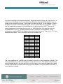
As you can see from Table 5, the user can select whether the 8 bits of status will be at the
beginning or the end of the data word. If the status bits are of no interest in a particular
application, they can be placed at the end of the data word and omitted by clocking out 8 fewer
bits each time. This translates into not only quicker transmission time but also a more
economical use of memory in the controller.
Like the M3000Si, one can choose between Standard and Trigger approaches to requesting
data however this must be programmed ahead of time since either request signal is received on
the same connector pins. Refer to the M3500Si User’s Manual for specifics.
Another major difference from the M3000Si is the provision of clock feed-back. The spiClockIn
signal is looped back to the controller as an encoder output. This allows the user to
compensate for propagation delays between the controller and the encoder since both the clock
and data signals can be sampled at the same physical point. Line drivers and receivers in both
the controller and encoder have inherent delays associated with them as well as the cable
between them. Without clock feed-back there could be a significant interval between requesting
data and receiving it depending on your cable length. The fed back clock signal will be delayed
the same amount as the data making it easier to synchronize them to each other.
MII5800Si and MII6800Si
The Mercury II 5800Si and 6800Si interfaces features up to 1.22nm resolution (14 bits) with a
user definable length on the position word. Based on how many inter-fringe bits (resolution) and
fringe-counter bits (range of travel) the user configures, the entire data word can range from 27
to 58 bits. It supports clock speeds between 30MHz and 50MHz. Table 6 shows the data word
format.
MSB
Start Bits
1 0 1 1
LSB
Position Word
4-35 Bits
IW
RL
LL
Status Bits
Y
R
S
C
Sp
0
CRC Word
6 Bits
Stop Bits
5 2 1 0
Table 5: 38 bit data word
The data word always begins with the same four start bits: 1011, followed by the position word,
then the 9 status bits, the cyclic redundancy check bits and the stop bits: 1011. The status bits
are defined as shown in Table 7. These bits will be all zeros during normal operation and when
not over the index mark or either of the two limit regions.
TN1301 – MicroE Serial Word
Page 5
© 2015 MicroE