1
FPGA Virtual Air Hockey
A Design Project Report
Presented to the Engineering Division of the Graduate School
of Cornell University
in Partial Fulfillment of the Requirements for the Degree of
Master of Engineering (Electrical & Computer)
by
Ping-Hong Lu
Project Advisor: Dr. Bruce R. Land
Degree Date: May 2008
Abstract
Master of Electrical and Computer Engineering
Cornell University
Design Project Report
Project Title: FPGA Virtual Air Hockey
Author: Ping-Hong Lu
Abstract: A virtual air hockey game was designed that blends together many aspects of
embedded systems design in electrical and computer engineering to create an interactive
game that is sophisticated yet intuitive to play. The video game is implemented on the
DE2 FPGA educational development board made by Terasic for Altera's Cyclone II
processor. The FPGA is used in combination with a CCD camera for video input as well
as a monitor and speakers for game output. The camera tracks movements of LED
paddles through image processing techniques and the players move the paddles to strike
a virtual puck which is displayed on the monitor along with the on-screen paddles. In
addition to synthesizing basic hardware on the DE2, a general purpose CPU, called the
Nios II, is also instantiated on the board, which runs high-level C code. The dynamics of
the game is coded in C. The result is a fully interactive game in which the users'
movements of LEDs register as movements of paddles in the virtual air hockey game,
accompanied by sound.
Report Approved by
Date:
Project Advisor:
2
Executive Summary
This design project was inspired by my interest in games and gaming console
design. With the current generation of gaming consoles incorporating cameras,
microphones, and motion sensors as inputs to the games, it was decided that a similar
approach would be used. It takes a simple game like air hockey and incorporates image
processing to mimic actual hand-controlled motion of the on-screen paddle. The image
processing accurately captures the velocities of the users' movements to realistically
affect the dynamics of the game.
The game utilizes sophisticated dynamics for controlling the puck movements, as
well as many low-level hardware modules including video output, audio Digital to
Analog Conversion, and image processing. Since the VGA only has whole numbered
pixel resolution, 32-bit fixed point arithmetic allowed quick conversions of puck position
between integer values and mixed fractional values. A high-resolution camera for the
system used in conjunction with various digital image processing techniques such as
dilating and eroding allowed accurate position detection for the paddles.
Originally, I had envisioned implementing the game on a traditional
microcontroller. However, the idea of using reconfigurable hardware was appealing in
that future firmware upgrades could also potentially change the features of the hardware
and add or reduce functionality where needed. This last point is certainly relevant
considering the existing game consoles on the market today already support firmware
updates through internet connections. The entire project was done on the DE2 FPGA
development board and TRDB_DC2 1.3 Megapixel camera, both made by Terasic
Technologies, a speaker, a VGA monitor, and two LED-mounted paddles. The hardware
was programmed in Verilog and the Nios II CPU was programmed in embedded C.
The project was a great success, and the game play is both natural and fun. I am
extremely satisfied with the results and found the entire process very rewarding.
3
Table of Contents
Virtual Air Hockey
Abstract ...............................................................................................................................2
Executive Summary ............................................................................................................3
Introduction ....................................................................................................................................5
Design Requirements .....................................................................................................................5
Background.....................................................................................................................................6
Interactive gaming...............................................................................................................6
Air hockey ...........................................................................................................................6
Range of Solutions ..........................................................................................................................7
Game Input ..........................................................................................................................7
Video Output .......................................................................................................................9
Sound Output.....................................................................................................................10
Final Project Definition .....................................................................................................11
Design and Implementation.........................................................................................................12
Video Input Hardware .......................................................................................................12
Paddle Control Hardware ..................................................................................................13
Video Output Hardware ....................................................................................................16
Sound Output Hardware ....................................................................................................16
Miscellaneous Hardware ...................................................................................................17
Game Dynamics Software.................................................................................................18
Fixed-point Arithmetic .........................................................................................20
Puck Velocity Integration & Position Calculation ...............................................20
Physics Modeling .................................................................................................21
Starting, Scoring, & Ending Rules .......................................................................25
Debugging .........................................................................................................................26
Results............................................................................................................................................28
Future Works................................................................................................................................32
Conclusions ...................................................................................................................................33
Acknowledgements .......................................................................................................................34
References .....................................................................................................................................35
Appendix A – Glossary of Terms Used.......................................................................................36
Appendix B – Hardware Schematics and Diagrams .................................................................37
Appendix C – Virtual Air Hockey Photographs........................................................................38
Appendix D – User’s Manual ......................................................................................................41
Appendix E – Code.......................................................................................................................42
4
INTRODUCTION
Upon starting my Masters of Engineering design project, my goal was to create an
embedded systems project that would utilize both knowledge of hardware organization
and software development. To achieve this goal, the idea to create a video game that was
both interactive and intuitive to play was born. The idea of physical movements
controlling the game was influenced by the present state of the gaming industry, and
provides an added fun-factor for the user who feels more involved in the game
play. Even a seemingly simple game such as air hockey involves a great deal of
electrical and computer engineering knowledge. By organizing the hardware on the
FPGA for fast response as well as programming a general purpose CPU instantiated on
the FPGA to run high-level logic, I was able to create the game environment I aimed
for. Through use of the system, one can immediately see that it is highly responsive to
the user's movements, and the dynamics of the game emulates the real experience very
well.
DESIGN REQUIREMENTS
There were three main requirements for this video game which ultimately shaped
the resulting product. The most important design requirement was the responsiveness of
the system. For the most part, this meant that the image capturing and outputting needed
to be fast and therefore implemented in hardware which required no additional software
logic. The game dynamics could take a little longer since the game needed to be slow
enough for humans to play, and was accordingly implemented in software running on the
Nios II CPU. Other requirements were that the video game run smoothly with no lags or
glitches in the game play and simply that it should feel like a real game of air hockey.
This last requirement is a bit subjective and required adjustments made by iterative trial
and errors.
The requirements of this project are summarized as the following:
-
Good responsiveness, the actions feel like an extension of the user’s body
-
Precise and accurate game dynamics
-
Overall experience like playing real air hockey
5
BACKGROUND
Interactive GamingWith the recent burst of interactive video game consoles hitting the market, it is
clear that there is much consumer interest in interactive gaming. The
accelerometer/gyroscope technologies combined with infrared position triangulating in
the Nintendo® Wii allow users to aim a gun or slash a sword, while the SIXAXIS tilt
sensitive controller for the Sony Playstation® 3 allows players to guide a flying object
with the tilt their hands instead of the motion of their thumbs. Other forms of interactive
games also exist, such as stepping on pressure-sensitive pads or playing musical
instruments along with a specific rhythm. While the packaging and forms may be
different, the goals of these systems are all the same: provide control input to the game
through the user’s physical motion or sounds instead of key presses. The game input
devices can be either digital, in the case of games like Guitar Hero, or analog like in
Karaoke Revolution.
Air HockeyThe game of air hockey adheres to fairly straightforward rules that can be
modeled by a physics engine quite nicely. The game can be represented on a two
dimensional space from a bird’s-eye perspective which is also ideal for displaying
relatively simple graphics. The energy input to the system are typically all impulses
which translates to a sudden change in the puck’s acceleration, or jerk, and small amounts
of friction and energy dissipation due to inelastic collisions will remove kinetic energy
from the puck and slow it down. The physics differ from elastic collisions like many
billiard ball simulators. One reason is that the mass of the paddle is considerably larger
than the mass of the puck because the user holds onto the paddle. In other words, the
conservation of momentum (p = m * v) is trickier to express, assuming an extremely
large mass of the paddle with a non-completely elastic collision. However, aside from
paddle/puck collision math, the overall behavior of the system like position and velocity
can be modeled nicely in a 2-dimensional coordinate system.
6
RANGE OF SOLUTIONS
To create a realistic game experience, many possible implementations and ideas
were considered. Much cost-benefit analysis had to be taken into account and the
following were things that were considered in ultimately coming up with the project
solution.
Game Input
Upon coming up with the idea of the air hockey game, the first possibility for
game input was to use accelerometers in conjunction with a camera so that I could
measure actual acceleration, and therefore determine the force at the time of “contact”.
The accuracy of the collision force made this option fairly attractive. However, in
researching wireless radio transmissions, it was determined that the overhead of both cost
and time did not warrant that level of precision measuring. Instead, simply using the
change in position from the imaging would have to provide sufficient data for the
dynamics of the system.
The next idea was to use just a camera to determine the position of the paddles.
The Sony PlayStation® 2 EyeToy camera uses edge detection and various signal
processing techniques to determine the user’s movements against the background.
Conveniently, Terasic Technologies makes a CCD camera for the FPGA board that was
ultimately used for this project. My idea was to draw upon principles similar to the
EyeToy but to make the processing easier by detecting distinct colors, for example. The
camera has a fairly high resolution that is capable of 1.3 Mega pixels which is more than
enough for my desired application.
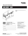
To ensure that the game can be played in all types of lighting, I decided to use
colored LEDs as inputs for the game. Unfortunately the sensitivity of photo capture is
different from human eyes and the colors of LEDs are not easily distinguishable as
recorded through the camera. The following figure is an example of what a blue and
yellow LED look likes through the camera, with the blue LED on the left and yellow on
the right.
7
Figure 1
Notice that the blue LED, while having some blue in the fringes, is almost completely
white. The yellow LED looks completely white, and differentiating the two in a reliable
manner could prove to be complex. Instead of color, the next choice for detection was to
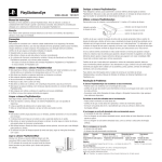
simply use light intensity, tracking a certain level of whiteness (an intense mixture of red,
green, and blue light), and splitting the playing space among the two players so that
player 1 cannot move into player 2’s space on screen.. Figure 2 is an example of what
the light intensity of an LED looks like up close, with a value of zero being the lowest
intensity (black) and five being the highest (white):
8
Figure 2
One limitation of this approach is that dispersed light sources in the same camera space
would need some sort of mechanism to decide which pixel would represent the paddle.
In other words, how do we process the peak values (i.e., 5) in Figure 2 in an orderly and
systematic fashion? The solution for this will be discussed in the DESIGN AND
IMPLEMENTATION section.
Video Output
The idea is to play this game on a large display. For that reason, considerable
time was spent considering the form of the video output. Digital outputs like HDMI or
DVI are fairly standard in new televisions and monitors. HDMI and DVI have the ability
to output tremendously high-resolution video of 1920 x 1080 and 1920 x 1200 pixels
9
respectively. In addition to the digital video formats, there is also NTSC video used in
standard television coaxial cables, and VGA for computer monitors. After considering
the multitude of video output formats, a VGA interface was chosen for several reasons.
First, the high definition digital formats are completely excessive for the type of video
this system expects to output, which are simple geometric shapes with solid colors. The
digital formats are also strictly specified so the time put into implementing and
debugging the video output to conform to the strict standards would not be worth the
benefits (which this project will be unable to make use of, anyway).
The VGA specifications are very similar to the NTSC protocol used for standard
analog television sets, with two differences. One difference is that there are separate
analog lines for each of color: red, green, and blue. The other major difference is that
there are separate lines for horizontal and vertical sync pulses.
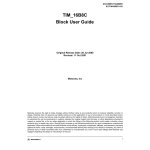
The basic premise of VGA is that the output device will send a repeating series of
horizontal and vertical sync pulses to the monitor, which specifies the exact pixel to
brighten or darken. Each horizontal sync pulse indicates to the monitor to shift its focus
to the next pixel on the same line, while each vertical sync pulse tells the monitor to
move on to the next line. Each pixel can be set to a specific red, green, and blue value
depending on the voltage level of the respective color input, with a higher voltage level
corresponding to a brighter color. Figure 3 is an example of what a sample VGA video
signal may look like for the green color with respect to the sync pulses:
Figure 3
Sound Output
The aim for this project is to create a rich gaming experience, and no game would
be complete without sound effects. There are many viable techniques for generating
10
sounds, and the one chosen for this project is direct digital syntheses (DDS). The general
functionality of DDS is explained as follows: a calculated constant number called a
phase increment is added to an n-bit register every N clock cycles, causing the n-bit
register to overflow at some constant rate. At the same time, the top x-bits (where x < n)
of that register are used as index values for a table with y elements (2x ≥ y). This table is
the digital values of a single sine wave spread out evenly over y elements. These digital
values are sent to the DAC and an analog since wave is generated. To change
frequencies, simply change the constant value that is added to the n-bit register.
Mathematically expressed, the formula is:
φincrement =
freqsin e * 2 n * N
clk
By correctly choosing the phase increment based on your known clock and N values, a
sine wave with the desired frequency can be created. Notice that as you increase the sine
frequency by using higher increment values, the time resolution of the sine wave gets
worse and worse.
Final Project Definition
The final project is summarized as follows:
-
Game input of detecting LED movements through a digital camera
-
Game dynamics engine based solely on LED positions
-
Video output via VGA interface
-
Sound generation through Direct Digital Synthesis
11
DESIGN AND IMPLEMENTATION
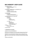
This section details the video input hardware, paddle control hardware, video output
hardware, sound output hardware, and other miscellaneous hardware, as well as the game
dynamics software. The block diagram of the virtual air hockey system is show below:
Image Filter
SDRAM
Controller
CCD Camera
LED
Paddles
Display
Logic Hardware
VGA
Controller
Monitor
Input
Outputs
Paddle
Positioning
Nios II CPU
(Game Dynamics)
Audio
DAC
Speaker
Figure 4
Video Input Hardware
The CCD camera uses a 25 MHz clock that is derived from the internal 50 MHz
clock divided by two. The module takes control inputs to start, stop, and reset the camera,
and outputs 10-bits of raw data on the mCCD_DATA bus. That bus is an input to the
module RAW2RGB, which then separates the raw camera information into red, green,
and blue values in for each pixel position. Note that the CCD camera code is provided by
Terasic with no changes made. More design details of the code can be found from
Terasic at http://www.terasic.com.tw/cgi-bin/page/archive.pl?Language=English&No=50.
The CCD camera's information is stored in on board the SDRAM memory. The
SDRAM contains 307,200 pixels of information per frame (640 x 480) but less than 60
percent of those pixels are used because the video that is generated is a 600 x 300. It
would have been desirable to have the camera skip the unused video space so that each
frame took only 58.6 percent of the time it actually takes. However, after thorough
research and analysis, it was determined that the TRDB CCD camera cannot be hacked to
12
display less information, and using anther camera was not a realistic option. As a result,
the data path of the camera’s information and identifying the source was a source of
performance constraint. As I found out later in the project, this was actually the largest
constraint in the project, and this will be discussed further in the RESULTS section of the
report.
Another constraint on the system is that the camera will pick up light reflection
from the paddle LED. In order to avoid false position calculations, the system needs to
be used in an environment free of reflective objects in the camera’s field of view. This
includes the actual playing surface, and during development and testing a large nonsmooth black piece of paper was used under the playing area.
Paddle Control Hardware
The paddle detection hardware is one of the more complex sections of this project
with many steps in the process. First the red, green, and blue data for each pixel in the
SDRAM is processed by image filtering hardware to even out extraneous data. That
filtered data set is used to determine the center locations of the two paddles, and finally
when each pixel is output on the VGA, it’s proximity to the center of the paddles are
checked and the right action is taken in drawing the pixel.
To perform the image filtering on the red, green, and blue values of each pixel in
SDRAM, there are three special shift-registers called taps that shift in the information
every clock cycle. The taps are unique because as their name suggests, they allow the
hardware to tap each position of the shift-register to access its bits. The taps were created
using the MegaWizard Plug-In Manager in the Quartus II IDE. For more information on
how these work see: http://www.altera.com/literature/ug/ug_alt_shift_taps.pdf. The taps
are used to perform two morphological image processing techniques called erode and
dilate which fade away the edge of the foreground and background respectively. The
information is then used to compare against the next state of the shift-register and if it can
detect whether “change” (motion) has occurred or not. If no motion has been detected,
the VGA output address going to the Nios II retains the value from the previous position.
Next, a finite state machine was utilized in determining the location and drawing
of the two paddles for many reasons. One of the reasons is that a scheme is necessary to
13
manipulate the video memory only while the sync signals are asserted so that no video
artifacts show. Another reason is that the FSM provides a systematic way to detect
motion in which the playing space which has been divided into two regions, one for each
paddle. Use the figure below as a guide in following the FSM description. While there
are only a few number of states in the state machine, the last state is fairly complex with a
lot of parallel hardware so please review the following carefully.
Init
test1
test2
test3
Enter here upon reset.
Assert “New Frame”
if x and y coordinates
of the current pixel has
wrapped back to
beginning.
Calculate the distance
of the current pixel from
the centers of the two
paddles. Also calculate
the distance of the
current pixel from the
center of the puck.
Illuminate the current
pixel based on its
address, and proximity
to the paddles and
puck.
Figure 5
The state machine is clocked by the rising edge of 50 MHz clock and begins in the “init”
state. If at any time KEY[0] s pressed, the state machine returns to the “init” state. No
action is taken in the init state except to set the state variable to “test1”.
In the state “test1”, the goal is to record the most recently known location of the
LEDs in each playing space. Each cycle of the 50 MHz clock also increments the
mVGA_X and mVGA_Y variables which have red, green, and blue values of mVGA_R,
mVGA_G, and mVGA_B. Using this, the values in mVGA_R, mVGA_G, and
mVGA_B are checked against the filtering threshold to determine the center of the LED.
Undoubtedly, there will be multiple pixels who satisfy this condition, and to avoid having
a moving virtual paddle for a static LED, a first-satisfied scheme is utilized where one a
fresh frame has started and a “LED center” has been detected, the state machine does not
14
attempt to update the paddle center addresses until a new frame begins, which is defined
by mVGA_X == 20 and mVGA_Y == 20. For example in Figure 2, the algorithm would
always identify the top-left most pixel labeled 5 as the center of the paddle. If no LED
center is found the previous paddle locations are kept. Such a case would be possible
only if the LED leaves the camera view, or is turned off. Once these steps are completed,
the state variable is updated to “test2”.
State “test2”, is used to determine the surrounding pixels of the paddle centers,
which were recorded in state “test1”. To do this, the paddle center’s x and y addresses
have mVGA_X and mVGA_Y subtracted, and that difference is stored in registers
DIFF_X_1, DIFF_Y_1, DIFF_X_2, and DIFF_Y_2. Unlike programming in sequential
languages like C and Java, Verilog cannot perform the calculations in states “test1” and
“test2” in the same cycle because “instructions” are actually dedicated hardware on the
DE2 board and happen concurrently at the clock-edge with no knowledge of data
dependencies. In addition, the puck’s x and y addresses are also subtracted from the
VGA x and y address and recorded. The state variable is then set to “test3”.
In state “test3” the actual drawing of borders, paddles, and puck occur. The
borders are drawn by using absolute addresses of mVGA_X and mVGA_Y, where the
border is a rectangle defined by the points (20,100), (620,100), (20, 400), and (620,400).
Please note that in the VGA coordinate system the Cartesian coordinate system has been
reflected over the y-axis, or in other words, the positive direction of y is down. In
drawing the paddles, the previously calculated difference values are used to determine
how far away from the center of the paddle the current pixel is. If the current pixel is a
within a defined radius of the center, that pixel is illuminated according to the
corresponding paddle color. And lastly, the illumination of the puck is done in the same
way as the paddles, with a slight difference in that the x and y coordinates of the puck’s
center are passed from the NIOS II CPU via a bus instead of being detected by the
camera. When this is all done, the state variable is set back to “test1” and the process
begins anew.
Users should note that there are limitations on the camera and its refresh rate. It is
possible for the user to move the LED faster than the camera’s refresh rate which results
in a huge jump in the paddle’s position. This is because the time between the previous
15
position and the new position detected by the camera is so long. This was exactly the
problem that was described in the Video Input Hardware and really has no solution in
hardware. While it is possible to detect the huge jump in software and extrapolate some
trajectory (a straight line, for example), this was not done because of the additional
complexity that such a scheme would introduce.
Video Output Hardware
The VGA_Controller is clocked at 25 MHz and provides the monitor with the
information to be displayed on the screen. The outputs of the module are on five lines,
VGA_Red, VGA_Green, VGA_Blue, VGA_HSYNCH, and VGA_VSYNCH. The
VGA_Controller module keeps track of incrementing and resetting the horizontal and
vertical synch values so that it outputs the correct sequence of horizontal and vertical
sync pulses. The inputs to the module are the red, green, and blue information we wish to
output based on the red, green, and blue values stored at the x and y coordinate in
SDRAM. The red, green, and blue values we wish to output are set by the state machine
discussed earlier and use a blue value for the air hockey table border, white for the goals,
blue for player 1’s paddle, white for player 2’s paddle, yellow for the puck, and black
everywhere else. There are also two white boxes that are necessary to satisfy the “start
game” condition which will be covered further in the Starting, Scoring, & Ending Rules
section of the report. Again, these pixel values are only altered while the
VGA_HSYNCH and VGA_VSYNCH lines are asserted.
Sound Output Hardware
A phased-locked loop (PLL) is used to take one of the FPGA’s internal clocks of
frequency 27 MHz and output a 18.4 MHz clock which is subsequently used as the audio
control clock. A Quartus II IDE wizard, which generates PLL modules with a few highlevel design inputs, was utilized to create the PLL. The three other inputs into the audio
module are a reset delay line, an on/off signal, and a source select signal. The reset delay
signal is asserted by the Reset_Delay module when KEY[0], or the system reset button, is
pressed. The delay is to provide enough time for all components of the system to reach a
known steady state before continuing. The on/off signal is asserted for example when a
16
sound effect is needed. In the AUDIO_DAC module, a DDS system is used to generate
sine waves of different frequencies based on a phase increments which is depend on the
source select. The foundation of the code was used from Teraic’s TRDB camera’s
motion detection example, and more design details can be found at
http://www.terasic.com.tw/cgi-bin/page/archive.pl?Language=English&No=50. In
extending the code, multiple sounds for different circumstances with various frequencies
were added. This was accomplished by adding a source select bus to the AUDIO_DAC
module which controlled the phase increment. Each source can play for different time
intervals by having separate control lines for the on/off signal. For example, when the
puck reflects off of a border, ten cycles of 10 KHz sine wave is generated, but when the
puck enters a goal, a chime with increasing frequencies is played. The duration of the
tone was controlled by the on/off signal which can be controlled precisely by using a 24
bit counter. Because the sound generation hardware that is an input to the AUDIO_DAC
is clocked at 50 MHz, asserting the on/off signal for 50 million counts generates a one
second tone. In the case of the chime that is played when a player scores a goal, four
different thresholds were used for the 24-bit counter and during each threshold, a
different source select value was used, causing the AUDIO_DAC to use phase
increments corresponding to each of the different source selects. The result is a chime
that increases in frequency three times every 63 ms for a total 252 ms, and it sounds quite
good. For a waveform of the output signals, please see the RESULTS section.
In hindsight, if I were to do the project again, I would write the AUDIO_DAC
module from scratch rather than start with Terasic’s code as a foundation. The main
reason is that the lookup table only has 48 elements because the original hardware only
output a 1 KHz sine wave. The sound output is very good when simply multiplying the
frequency, but in trying to create musical notes, i.e. frequencies less than 1 KHz, the DDS
was limited by the number of A/D values it had in the table and the output suffered as a
result.
Miscellaneous Hardware
The DE2’s on-board 7-segment displays were used to indicate each player’s
current numerical score. To do this, a lookup table module was created which took a 4-
17
bit input and output 7-bits. The four bits represent 16 possible values ranging from 0x0
to 0xh, and a lookup table maps each of the 16 values to a corresponding 7-bit pattern
that make up alphanumeric outputs on the 7-segment display.
In addition to the 7-segment displays, 18 general purpose red LEDs exist on the
DE2 which were used during development to blink on and off depending on the specific
need of the task. The 7-segment displays are active low, while the LEDs are active high.
As mentioned previously in the Sound Output Hardware section, there is a
Reset_Delay module on the board that detects the KEY[0] button press. When this
button is pressed, three different delay lines are controlled, each with its own time delay
before it is asserted. The delay values used by the Sdram_Control module is
approximately 41.9 ms, the delay for the CCD_Capture, RAW2RGB, and AUDIO_DAC
modules are approximately 62.9 ms, and the delay for the VGA_Controller is 83.9 ms.
Game Dynamics Software
A Nios II/f core (fast) was used in implementing the game dynamics. The
Quartus II IDE has a built in module called the SOPC (System On Programmable Chip)
Builder which takes care of generating the general purpose CPU out of your high level
design requirements. See the figure below for the specific SOPC Builder parameters.
18
Figure 6
The Nios II/f has several advantages over the Nios II/e (economy) and Nios II/s
(standard) in that it has a six-stage pipeline to achieve greater throughput, or instructions
per second, and also has single-cycle hardware multiply and barrel-shift operations,
something that is very useful for this project.
The default memory available to the Nios II is either SDRAM or M4K memory,
and the choice can be configured through the Nios II IDE project settings. Since, our
project utilizes the SDRAM to store the CCD camera’s data and M4K blocks are not
sufficiently large enough to contain this code space. Instead, the Nios II instantiated for
this project utilizes a 512k block of SRAM whose implementation was made available by
Terasic in the module SRAM_16bit-512k.
19
Fixed-Point Arithmetic
Fixed-point arithmetic was used to represent non-integer values. In the Nios II
architecture, int values are 32-bit values, so the top three bytes are used for the wholenumber value, and the lower byte is used for fractional values. The virtual decimal point
was located between the first and second low-order bytes and values to the right of the
decimal represented one divided by two raised to the position’s value (see figure 7).
Figure 7
For example, a hex value of 0x00000040 is ¼ because there is no whole-number value
and the fraction value is 1 divided by two squared. Conversion back to a rounded whole
number (basically a floor function) is to shift the fixed-point variable to the right 8-bits.
Conversion from integer would be to shift the value to the left 8-bits, and conversion
from a floating point value is to multiply the value by 256.0 (same as shifting left by 8
but keeps the correct data type) and to cast the result as an int to keep the 32-bits.
Therefore, when displaying video of a puck whose address is (450.25,300.5) will result in
the puck being at location (450,300).
Puck Velocity Integration & Position Calculation
In each iteration of the Nios II main loop, a simple integral is performed to
determine the new position of the puck. In performing this integral, it is assumed that the
main loop runs at a regular interval so that the time between each position update is
constant. To validate this assumption, a simple exercise was conducted where the Nios II
toggled a GPIO on the DE2 board each iteration of the main while-loop. The CPU’s
tight-loop takes at 40 μs with slight variance at times. The worst observed variance was
48 μs. However, the frequency of the variances was very low, about 4 out of every 100
20
iterations. With the worst possible variance being 20% but only occurring 4% of the time,
one can see that the variance is fairly insignificant. With such low margins of error, it
was determined that this method of calculating integrals was acceptable.
Having established that a mostly constant time interval exists between position
updates, the integration is performed by simply adding the current velocity to the current
position. Of course, collisions with the boundaries of the air hockey table as well as
paddles and the goal conditions are checked prior to moving the puck so that impossible
conditions are avoided when possible. However, it is possible that the puck’s velocity is
such that in one time-step, it moves from near an object (wall or paddle), to overlapping
the object, and this is not checked prior to moving the puck. This usually happens for
only a single frame and is virtually undetectable by the human eye at game speeds. The
code will reflect the object in the appropriate direction assuming the point of collision to
be where it should have been, rather than where it currently is. See APPENDIX E for
implementation details. There are rare instances where the puck can move completely
through a paddle in one cycle of the main loop. While it is possible for this to happen,
the occurrences are rare because the speed of the puck needs to be near the maximum
allowed value and the user must be moving the paddle in the opposite direction at a high
speed as well. I decided that the complexity of detecting this corner case is not worth the
payoff in the context of this project, especially since there is no protection against the
user moving the LED too fast for the camera, and having the paddle jump
discontinuously. Future work may include exploring the many possible solutions for
corner cases.
Physics Modeling
The physics involved in air hockey is modeled in this game by keeping track of
the puck’s x and y-velocities as well as calculating the paddles’ x and y-velocities in realtime. The puck’s movements are straight with very little friction, just like real air
hockey. The velocity vector changes directions with some speed loss upon colliding with
static objects on the table, with the energy being transferred from kinetic energy to
friction heat and sound energy. This is done in software reducing the absolute value of
the velocities upon a collision and asserting an output line to the AUDIO_DAC module
21
to create a sound. For simplicity, the speed of the puck was not taken into account and a
constant energy loss was implemented, although future implementations could certainly
improve upon this by making the energy loss more accurate to the physical world.
Energy input is achieved by striking the puck with the paddle, with more energy
transferred to the puck when the paddle is moving faster. This is good in that there is
never any constant acceleration (we ignore force of friction because this is virtual air
hockey, after all). The tricky part is that the paddle has a much larger mass compared to
the puck and the paddle’s velocity remains unchanged after the collision. Therefore the
concept of conservation of momentum where the momentum of the entire system
(consisting of n objects with mass m and velocity v defined below)
n
∑m
i =0
i
* vi
before the collision is equal to the momentum of the entire system after the collision is
computationally hard because there is no known mass of the paddle. There was some
leeway in designing the non-completely elastic collision, because the precise amount of
energy lost to sound and friction depend on many factors in the real world. In adding
energy to the puck, my design based the speed increase on the current speed of the puck
and the speed of the paddle at the time of collision, with a saturation point near the
maximum allowed puck speed defined by the constant MAX_SPEED. For exact
implementation details, please refer to APPENDIX E.
Even though the code is quite lengthy, the actual logic for changing directions and
speeds based on collisions with walls and paddles is fairly straightforward. The wall
collisions require simply detecting the x or y address of the puck to be greater than or less
than the boundary depending on the wall in question. For the paddles, the design broke
down the different scenarios in which collisions could occur. Based on the code prior to
the dynamics calculations, a flag is set based on the distance between the paddle and puck
being greater or less-than-or-equal-to twice the radius of the puck and paddle (they share
the same radius lengths). Figure 8 is an accompanying partial flow chart meant to
facilitate the understanding of the collision logic and is not representative of the entire
code. It was determined that the logic would first determine which direction the puck
was traveling (positive x & positive y, positive x & negative y, negative x and positive y,
22
or negative x and negative y). In each of these scenarios, the collision with the puck is
then categorized again. This time, we are interested in which area of the paddle makes
contact with the puck. If you think of the puck being at the origin of a two-dimensional
graph, then the x and y-axis’ divide the paddle into 4 quadrants. Similar to the Cartesian
coordinate system, the design refers to the top right as quadrant I, bottom right as
quadrant II and so on. Once these two parameters of the collision scenario are known,
the appropriate reflecting direction is determined. In referring to the figure below, please
remember that it is not a complete representation of the dynamics engine.
No
Yes
Counter is
200?
Counter++
Start
Yes
Collision
frozen?
Counter is 0
Bounce puck
up and left
Yes
Yes
Save prev.
pos. &
update pos.
Reflect off walls
and change
speeds if needed
No
Update speed
& freeze
collisions
Yes
Collision
Flag is 1?
Paddle’s 1st
quadrant?
Puck
moving
down &
right?
No
Puck
moving up
& right?
Bounce puck
down and right
No direction
change
Paddle’s 4th
quadrant?
No
Bounce puck
up and right
No
Yes
No
Paddle’s 3rd
quadrant?
Yes
Yes
No
No
Etc.
Figure 8
23
Lastly, the speed of the puck resulting from a paddle collision occurs as a function
of the paddle speed. A conscious decision was made to transfer energy from the paddle
to the puck non-linearly so that at low speeds the resolution of speed differentiation is
large but as the paddle moves faster the speed increases in larger step intervals. This is to
provide precise control at low speeds when users want to control the puck using finesse,
but can also take hard shots at high speeds. The calibration for this was done over many
trials and was largely subjective to what I felt was a good level of game control. There
was one design problem that surfaced during the testing – the sampling rate of the paddle
positions is so fast that the difference in the LED positions from the user’s movements
were registered as zero for a majority of the movement duration. See Figure 9 below for
one example of the perceived X position differences when moving the LED at a constant
low speed.
Sample
1
2
3
4
5
6
7
8
9
10
11
12
13
14
15
16
17
18
19
20
21
22
23
24
25
Original X Position Delta
Calculated X
Calculated X
Sample Delta
Delta
0
26
0
0
27
0
76
28
64
0
29
0
0
30
0
0
31
0
46
32
0
0
33
83
0
34
0
21
35
0
0
36
47
0
37
0
0
38
48
0
39
0
57
40
0
0
41
23
64
42
0
0
43
0
0
44
0
23
45
45
0
46
0
0
47
0
0
48
49
45
49
0
0
50
0
Figure 9
24
The problem was remedied by inserting logic to detect a lengthy period of zero
movement before registering the speed as zero, in this case 15 consecutive zeros. This is
not unreasonable since calculations are separated by about 40 μs so 0.6 ms after user has
stopped moving, the game will register that the paddle is static, which is virtually
unnoticeable to the human player. The results of applying the algorithm on the data in
Figure 9 are shown below in Figure 10.
Sample
1
2
3
4
5
6
7
8
9
10
11
12
13
14
15
16
17
18
19
20
21
22
23
24
25
Adjusted X Position Delta
Calculated X
Calculated X
Sample
Delta
Delta
0
26
45
0
27
45
76
28
64
76
29
64
76
30
64
76
31
64
46
32
64
46
33
83
46
34
83
21
35
83
21
36
47
21
37
47
21
38
48
21
39
48
57
40
48
57
41
23
64
42
23
64
43
23
64
44
23
23
45
45
23
46
45
23
47
45
23
48
49
45
49
49
45
50
49
Figure 10
Starting, Scoring, & Ending Rules
In order to start a game, both players must be ready. To indicate this, a start
condition must be satisfied before the Nios II will populate the puck. The starting
condition is met by each player placing his or her paddle within a specified area on the
25
screen. This area is highlighted by the display logic hardware and will remove the box
when a signal from the Nios II indicates that the game has begun. After asserting this
logic line, the Nios II will populate the puck in the middle of the table in the reach of both
players. In the course of play, if the puck hits the goal (white) region on the east/west
walls, the scoring condition is met and a point is awarded to the player opposite of the
goal that was scored upon. Afterwards, the puck is re-populated on the side of the player
that was scored upon.
Debugging
The debugging process was a conducted by utilizing the hardware’s LED’s and
print statements, as well subjective methods for the “look and feel” aspects. The 18 red
LEDs on the DE2 helped show the state of certain variables in real time and were a lowcost method of debugging without introducing extra delays because it is completely done
in hardware. For more complex tasks that required more details, print statements were
used through the JTAG UART on the DE2. The print statements were extremely useful,
but they introduced some delay into the calculations that depend on constant time so they
were avoided when possible. Additionally, I used my own judgment in determining what
a realistic reaction to collisions was. This included decisions like how much to increase
the puck’s speed based on how “hard” (velocity) you hit the puck. This was fairly
arbitrary because there is no known mass of the two objects and no good way to
determine just how the energy is conserved.
Some interesting bugs were observed in the course of this project. In my first try
at VGA video through the FPGA, I encountered problems where the pixel changes were
not where I expected them to be. This was a result of executing two calculations that
needed to be done sequentially in the same state in the FSM. That meant that while I
wanted the code to be run one after the other, they were actually being run
simultaneously in hardware. Another bug was seen which eventually led to the addition
of the Freeze_Collision flag. The symptoms were erratic puck/paddle collisions upon a
moderately fast collision. The reason for this was that the updating of the puck’s position
at high speeds would draw the puck overlapped with the paddle. This of course is a
collision scenario and the puck’s direction and speeds are updated. In the very next
26
update, the puck is still somewhere overlapping the paddle, and another direction and
speed update occurs. This problem of multiple collisions detected as a result on one
collision was compounded by the fact that the user is moving the paddle, usually further
towards the center of the puck. The solution was to set the aforementioned flag and to
not allow another collision to occur until that flag is de-asserted through counting down a
variable.
Finally, there were some obscure problems as a result of using the two integrated
development environments (IDEs). First, the Quartus II IDE’s SOPC builder’s naming
convention caused one problem where the orders of the Parallel Input/Out (PIO) busses
ended up in the wrong order. The reason for this was that the naming convention used
for this project was numbering all inputs and outputs sequentially. This worked fine for
Out0 through Out9, but as soon as Out10 was added, everything stopped working.
Digging into the generated Verilog file, bigNios.v, it was later revealed that the order
used by the SOPC builder was Out0, Out1, Out10, Out2, etc. which is in alphanumerical
order. Once the bus ordering in the high level Verilog code was switched, the code
worked flawlessly. The problem encountered with the Nios II IDE was also non-intuitive,
and the problem occurred when I made a copy of my source code and placed the copy in
the same directory as the original source file. This was done because I was about to make
dramatic changes to the code and I wanted to retain a copy of the working code.
Subsequent changes to the original source code made no differences in the behavior of
the program, which was extremely puzzling. The reason for this turned out to be that the
copy of the original was being compiled and run on the board instead of the original
source file because the name of the copy file came before the name of the original file,
and the builder took the first main function it saw. In this scenario, I would have at least
expected the code to not run or throw some warnings during compilation, but it did
neither of those.
27
RESULTS
The overall results were very positive. The video output of the puck movement
showed no artifacts when the game speed was increased during testing. The puck lost
video continuity when the puck began traveling at about 13 pixels per frame which makes
sense since the radius of the puck is also about 13 pixels. Generally during the course of
play, the puck velocity never reached 1.3 pixels per frame (10% of 13 pixels per frame)
which is a fairly conservative measure of video continuity. Furthermore, fear of
discontinuity is not even an issue in this application since a puck traveling that fast is not
conducive to a realistic gaming environment.
The paddle detection was very precise with LED position detection resolution of
approximately 1 cm when played from 2 feet away from the camera. This was far better
than my expectation. In contrast, the speeds at which the user could move the LED and
have the movement registered in a continuous manner were somewhat disappointing.
This was the result of the CCD camera taking so long to capture one frame of information
and moving onto the next frame. This result forced the game dynamics to be more
exaggerated at medium speeds, so that users can still perform hard shots while not losing
their paddle on the screen. In general, users became accustomed to the limits of the
camera very quickly and controlled the paddle expertly. I was also satisfied by the
overall ease of use of the system. New users required virtually no instructions and
learned the system through using.
The sound generation hardware worked quite well for the range of sine waves
which was 1, 2, 3, 4, 5, and 8 K Hz. As shown in Figures 11 and 12 below the 1 KHz
signal had plenty of samples and a solid time resolution to define a clean sine wave.
28
Figure 11
Figure 12
29
Figure 13
Figure 14
30
In Figure 13 and 14, the 8 KHz signal begins to show some distortions in the waveforms.
However, this worked perfectly as the 8 KHz sound was used to create a harsh, sharp
noise of the puck reflecting off of the border.
The goal to play this game in most conditions was also met, as testing in different
lighting conditions showed no artifacts. Of course, the testing was carried out with the
black paper below the camera and no other reflective objects in the view screen of the
camera.
The game dynamics felt very natural, even though some calibrations were purely
subjective. The approximations made for reflection angles were convincing for the
players while not introducing too much complexity into the physics engine. When the
puck is traveling at high speeds, there is an element of unpredictability in the reflection
when striking the puck with the paddle which provides an experience just like in real air
hockey. There were conscious design decisions to not address certain corner cases such
as paddles disappearing at one coordinate and reappearing at another or a puck traveling
at high speeds going through a paddle. These cases were ignored in an interest to keep
the code relatively straightforward, but some possible solutions were considered and
discussed in the DESIGN AND IMPLEMENTATION section of the report.
The lack of accelerometers was somewhat noticeable as sometimes there were
variances in the resulting puck speeds after collisions of seemingly similar speeds.
However, the variances were on the order of ± 3 speed increments, or 1.5 pixels per
position update which is noticeable but certainly acceptable.
31
FUTURE WORKS
This project has developed the foundation for a simple yet robust video game.
With some modifications, one can imagine implementing many other games which
feature similar physics. For example, games like virtual Pong are possible using the same
image tracking concept to control paddle movements. Some changes to implement
elastic collision physics would enable a game like billiards where the players control the
pool cues via image tracking. Collaborative games like curling where one player throws
the rock and another player sweeps the ice with the broom is extremely conducive of the
image tracking technology as well as the distance calculating hardware already in
existence from this project.
While requiring slightly more work, it is also conceivable to take advantage of the
DE2’s Fast Ethernet Network Controller to implement a cross-board game where each
player has their own DE2, TRDC camera, and monitor. As an example, if the air hockey
game is used, each player may only see their half of the table, their own paddles and the
puck when it is in their playing space. With so many features available on this hardware,
the gaming possibilities are quite extensive.
In addition to other possible games, I believe that this project or parts of it would
be useful as laboratory teaching material for academic purposes, as this project
incorporates many aspects of DE2 programming like state machines, video generation,
CPU synthesis, and high level C code.
32
CONCLUSIONS
The results from the air hockey game were overall very positive. Taking into
consideration all of the unforeseen bugs and problems I ran into, the end product has met
the high expectations set at the beginning of the project.
The paddle control is very precise and smooth at moderate speeds which are
sufficient for the game play, and the video output is very stable with no flickering or
breaking whatsoever. The sound output is also very neat and adds significant depth to the
game play. The system is robust enough to play in different light settings, although care
needs to be taken to ensure there are no reflective objects within the range of the camera.
In addition to the positive performance of the system, I have learned a great deal
about game and gaming console design. Having previous experience in designing a
simple video game on an 8-bit microcontroller, the Nios II was a much more pleasant
experience. With its pipelined architecture, the faster throughput for computing was
instrumental in creating a rich gaming experience that required many calculations per
frame of video. In addition to the power of the CPU, creating dedicated audio and video
generation hardware was also a powerful tool. This hardware had a simple interface with
wires or busses to and from the CPU creating instant audio and video results with no
additional time spent by the CPU.
I feel that I was able to achieve the intuitive factor which I set out to accomplish
from the beginning. Much like the Wii, users were able to pick up a paddle and play the
game with a very small learning curve.
I am extremely pleased to have undertaken this project, as I was able to turn my
interests in gaming into an academic endeavor which was both enlightening and
educational.
33
ACKNOWLEDGEMENTS
There are some individuals to whom I am grateful in completing this project.
First, I owe many thanks to Dr. Bruce Land whose inputs and suggestions were vital to
my progress. I would like to thank Elissa Chin for all her support and for putting up with
my lack of communication during the long hours of solitude spent in lab. And lastly, the
facilities crew responsible for the maintenance of Phillips 238 digital lab has done a
tremendous job in making my second home an enjoyable place.
34
REFERENCES
1. “VGA Specifications” <http://web.mit.edu/6.111/www/s2004/NEWKIT/vga.shtml>
2. “Fixed Point Arithmetic”
<http://instruct1.cit.cornell.edu/courses/ee476/Math/index.html>
3. “Elastic and Inelastic Collisions”
<http://hyperphysics.phy-astr.gsu.edu/HBASE/elacol.html>
4. “Terasic TRDB_DC2 Camera Specifications and Documentation”
<http://www.terasic.com.tw/cgi-bin/page/archive.pl?Language=English&No=50>
5. “Altera Nios II CPU Specifications and Documentation”
<http://www.altera.com/products/ip/processors/nios2/ni2-index.html>
35
APPENDIX A – Glossary of Terms Used
Dynamics/Physics engine
- computer logic to simulate Newtonian physics models using variables like mass,
velocity, friction, and acceleration.
Cartesian coordinate system
- a two dimensional coordinate system consisting of an abscissa (x-coordinate) and an
ordinate (y-coordinate) where two points can uniquely identify every point in the plane.
- also known as the rectangular coordinate system.
Elastic collision
- a physical collision where the total kinetic energy of the system is the same before and
after the collision.
Inelastic collision
- a physical collision where the total kinetic energy of the system is not the same before
and after the collision.
- the kinetic energy that is not conserved is transferred to other forms of energy such as
heat and sound.
36
APPENDIX B – Hardware Schematics and Diagrams
Paddle Circuit Schematic
75 Ω
9V
System Diagram
See Figure 4
37
APPENDIX C – Virtual Air Hockey Photos
TRDB_DC2 1.3 Megapixel CCD Camera
DE2 Development and Educational Board
38
Homemade Paddles
System Setup Pt. 1 – Top
39
System Setup Pt. 2 – Bottom
Game Screen Shot
40
APPENDIX D – User’s Manual
1. Select a surface that is non-reflective.
2. Remove DE2 board and TRDB camera from packaging. Note: You must handle
the boards only on the ESD mat.
3. Connect the camera and the FPGA via the ribbon cable to the GPIO 1 expansion
slot on the DE2 board.
4. Fit the camera into slot in the middle of stand with the lens in the center and the
FPGA resting on the stand.
5. Connect the monitor’s VGA cable to the VGA port on the DE2.
6. Connect the speakers to the green port labeled “LINE OUT”.
7. Connect the PC to the DE2 using the USB cable to the port labeled “BLASTER”.
8. Connect the power cable.
9. Turn on the power supply with the red switch on the DE2 board.
10. Open the “DE2_CCD_Detect” project file using the Quartus II IDE on the PC.
11. Program the board by clicking on the third icon from the top right labeled
“Programmer” and click “Start”. Note: Make sure the device is on “USB Blaster”.
12. Press the pushbutton labeled “KEY3” on the DE2 to start the camera.
13. Open the Nios II IDE and select the workspace to be
“\DE2_CCD_detect_noos\software”.
14. In the “Run” menu at the top of the window, click on “Run…” and click on
“Run” in the bottom right of the new window.
15. When ready to play, each player must move their paddle into their respective
white boxes on the air hockey table.
16. First player to 10 goals wins.
41
APPENDIX E – Code
Verilog Code
Instantiated Nios II module
//============================= Nios II =============================//
bigNios nios2(CLOCK_50, KEY[0],
// parallel i/o
current_dram_addr_x, //In0
addr_valid,
//In1
current_dram_addr_y, //In2
current_dram_addr_x_2,//In3
current_dram_addr_y_2,//In4
start_game, // In5
DIFF_X_1_IN, // In6
DIFF_Y_1_IN, // In7
DIFF_X_2_IN, // In8
DIFF_Y_2_IN, // In9
GPIO_0[0],
// Out0
LED_RED,
// Out1
chime_sound, // Out10 - stupid naming convention
SPEED,
// Out2 - Actually, left player's score
X_ADDRESS,
// Out3 - Actually, right player's score
Y_ADDRESS,
// Out4
PUCK_CENTER_X, // Out5
PUCK_CENTER_Y, // Out6
sound_signal, // Out7
collision_sound,// Out8
suppress_boxes, // Out9 1 bit Suppress-Boxes signal
// lcd
LCD_EN, LCD_RS, LCD_RW, LCD_DATA,
// the_sram_16bit_512k_0
SRAM_ADDR,
SRAM_CE_N,
SRAM_DQ,
SRAM_LB_N,
SRAM_OE_N,
SRAM_UB_N,
SRAM_WE_N);
//=========================== End Nios II ===========================//
Paddle Detection & Video Generation
//==================== Paddle Detection & Drawing ===================//
always@(posedge CLOCK_50)
begin
if (mVGA_X == 20 && mVGA_Y == 20)
begin
NEW_FRAME_1 <= 1'b1;
NEW_FRAME_2 <= 1'b1;
end
if (!KEY[3])
42
begin
reset_pressed = 1'b1;
end
if (reset)
//synch reset assumes KEY0 is held down 1/60 second
begin
//initialize variables
CENTER_X_1 <= 20;
CENTER_Y_1 <= 20;
CENTER_X_2 <= 620;
CENTER_Y_2 <= 20;
state <= init;
//first state in regular state machine
end
else if (VGA_VS | VGA_HS) //modify display during sync
begin
case(state)
init:
begin
state <= test1 ;
end
test1: //locate center
begin
if (mVGA_R >= 10'b1011000000 ||
mVGA_G >= 10'b1011000000 ||
mVGA_B >= 10'b1011000000 )
begin
if (NEW_FRAME_1 == 1 &&
mVGA_X >= 32
&& // avoid left border
mVGA_X < 305
&& // to avoid being cut
mVGA_Y >= 112
&& // avoid top border
mVGA_Y < 388)
// avoid bottom border
begin
CENTER_X_1 <= mVGA_X;
CENTER_Y_1 <= mVGA_Y;
NEW_FRAME_1 <= 1'b0;
end
if (NEW_FRAME_2 == 1 &&
mVGA_X >= 335
&& // to avoid being cut
mVGA_X < 608
&& // avoid right border
mVGA_Y >= 112
&& // avoid top border
mVGA_Y < 388)
// avoid bottom border
begin
CENTER_X_2 <= mVGA_X;
CENTER_Y_2 <= mVGA_Y;
NEW_FRAME_2 <= 1'b0;
end
end
state <= test2 ;
end
test2: //calculate diff
begin
DIFF_X_1 <= mVGA_X - CENTER_X_1;
DIFF_Y_1 <= mVGA_Y - CENTER_Y_1;
DIFF_X_2 <= mVGA_X - CENTER_X_2;
DIFF_Y_2 <= mVGA_Y - CENTER_Y_2;
DIFF_CENTER_X <= mVGA_X - PUCK_CENTER_X;
43
DIFF_CENTER_Y <= mVGA_Y - PUCK_CENTER_Y;
state <= test3 ;
end
test3: // draw paddles
begin
// draw puck
if ((PUCK_CENTER_X != 0 && PUCK_CENTER_Y != 0) &&
(( DIFF_CENTER_X <= 8 && // the square
DIFF_CENTER_X >= -8 &&
DIFF_CENTER_Y <= 8 &&
DIFF_CENTER_Y >= -8)
||
( DIFF_CENTER_X == 9 && // the right arc
DIFF_CENTER_Y <= 6 &&
DIFF_CENTER_Y >= -6)
||
( DIFF_CENTER_X == 10 &&
DIFF_CENTER_Y <= 5 &&
DIFF_CENTER_Y >= -5)
||
( DIFF_CENTER_X == 11 &&
DIFF_CENTER_Y <= 3 &&
DIFF_CENTER_Y >= -3)
||
( DIFF_CENTER_X == 12 &&
DIFF_CENTER_Y == 0 )
||
( DIFF_CENTER_X == -9 && // the left arc
DIFF_CENTER_Y <= 6 &&
DIFF_CENTER_Y >= -6)
||
( DIFF_CENTER_X == -10 &&
DIFF_CENTER_Y <= 5
&&
DIFF_CENTER_Y >= -5)
||
( DIFF_CENTER_X == -11 &&
DIFF_CENTER_Y <= 3
&&
DIFF_CENTER_Y >= -3)
||
( DIFF_CENTER_X == -12 &&
DIFF_CENTER_Y == 0 )
||
( DIFF_CENTER_Y == 9 && // the top arc
DIFF_CENTER_X <= 6 &&
DIFF_CENTER_X >= -6)
||
( DIFF_CENTER_Y == 10 &&
DIFF_CENTER_X <= 5 &&
DIFF_CENTER_X >= -5)
||
( DIFF_CENTER_Y == 11 &&
DIFF_CENTER_X <= 3 &&
DIFF_CENTER_X >= -3)
||
( DIFF_CENTER_Y == 12 &&
DIFF_CENTER_X == 0 )
||
44
( DIFF_CENTER_Y
DIFF_CENTER_X
DIFF_CENTER_X
||
( DIFF_CENTER_Y
DIFF_CENTER_X
DIFF_CENTER_X
||
( DIFF_CENTER_Y
DIFF_CENTER_X
DIFF_CENTER_X
||
( DIFF_CENTER_Y
DIFF_CENTER_X
== -9 && // the bottom arc
<= 6 &&
>= -6)
== -10 &&
<= 5
&&
>= -5)
== -11 &&
<= 3
&&
>= -3)
== -12 &&
== 0 ))
)
begin
green <=
red
<=
blue <=
10'b1010100000;
10'b1010100000;
10'b0000000000;
end
else
begin
if ((CENTER_X_1 != 0
(( DIFF_X_1 <= 8 &&
DIFF_X_1 >= -8 &&
DIFF_Y_1 <= 8 &&
DIFF_Y_1 >= -8)
||
( DIFF_X_1 == 9 && //
DIFF_Y_1 <= 6 &&
DIFF_Y_1 >= -6)
||
( DIFF_X_1 == 10 &&
DIFF_Y_1 <= 5 &&
DIFF_Y_1 >= -5)
||
( DIFF_X_1 == 11 &&
DIFF_Y_1 <= 3 &&
DIFF_Y_1 >= -3)
||
( DIFF_X_1 == 12 &&
DIFF_Y_1 == 0 )
||
( DIFF_X_1 == -9 && //
DIFF_Y_1 <= 6 &&
DIFF_Y_1 >= -6)
||
( DIFF_X_1 == -10 &&
DIFF_Y_1 <= 5
&&
DIFF_Y_1 >= -5)
||
( DIFF_X_1 == -11 &&
DIFF_Y_1 <= 3
&&
DIFF_Y_1 >= -3)
||
( DIFF_X_1 == -12 &&
DIFF_Y_1 == 0 )
45
&& CENTER_Y_1 != 00) &&
// the square
the right arc
the left arc
||
( DIFF_Y_1 == 9 && // the top arc
DIFF_X_1 <= 6 &&
DIFF_X_1 >= -6)
||
( DIFF_Y_1 == 10 &&
DIFF_X_1 <= 5 &&
DIFF_X_1 >= -5)
||
( DIFF_Y_1 == 11 &&
DIFF_X_1 <= 3 &&
DIFF_X_1 >= -3)
||
( DIFF_Y_1 == 12 &&
DIFF_X_1 == 0 )
||
( DIFF_Y_1 == -9 && // the bottom arc
DIFF_X_1 <= 6 &&
DIFF_X_1 >= -6)
||
( DIFF_Y_1 == -10 &&
DIFF_X_1 <= 5
&&
DIFF_X_1 >= -5)
||
( DIFF_Y_1 == -11 &&
DIFF_X_1 <= 3
&&
DIFF_X_1 >= -3)
||
( DIFF_Y_1 == -12 &&
DIFF_X_1 == 0 )))
begin // blue paddle
green <=
10'b1010100000;
red
<=
10'b0000000000;
blue <=
10'b1010100000;
end
// draw left start box
else if ((suppress_boxes == 0) &&
(mVGA_X == 120 || mVGA_X == 119)
&&
(mVGA_Y >= 224 && mVGA_Y < 276))
begin
green <=
10'b1111100000;
red
<=
10'b1111100000;
blue <=
10'b1111100000;
end
else if ((suppress_boxes == 0) &&
(mVGA_X == 170 || mVGA_X == 169)
&&
(mVGA_Y >= 225 && mVGA_Y < 275))
begin
green <=
10'b1111100000;
red
<=
10'b1111100000;
blue <=
10'b1111100000;
end
else if ((suppress_boxes == 0) &&
(mVGA_X > 120 && mVGA_X <= 170)
&&
(mVGA_Y == 225 || mVGA_Y == 224))
begin
green <=
10'b1111100000;
46
red
blue
<=
<=
10'b1111100000;
10'b1111100000;
end
else if ((suppress_boxes == 0) &&
(mVGA_X > 120 && mVGA_X <= 170)
&&
(mVGA_Y == 274 || mVGA_Y == 275))
begin
green <=
10'b1111100000;
red
<=
10'b1111100000;
blue <=
10'b1111100000;
end
// draw left top border
else if ((mVGA_X == 19 || mVGA_X == 18)
&&
(mVGA_Y >= 98 && mVGA_Y < 225))
begin
green <=
10'b0000000000;
red
<=
10'b0000000000;
blue <=
10'b1010100000;
end
// draw left goal
else if ((mVGA_X == 19 || mVGA_X == 18)
&&
(mVGA_Y >= 225 && mVGA_Y < 275))
begin
green <=
10'b1111100000;
red
<=
10'b1111100000;
blue <=
10'b1111100000;
end
// draw left bottom border
else if ((mVGA_X == 19 || mVGA_X == 18)
&&
(mVGA_Y >= 275 && mVGA_Y < 403))
begin
green <=
10'b0000000000;
red
<=
10'b0000000000;
blue <=
10'b1010100000;
end
// draw top left border
else if ((mVGA_X >= 19 && mVGA_X < 320)
&&
(mVGA_Y == 98 || mVGA_Y == 99))
begin
green <=
10'b0000000000;
red
<=
10'b0000000000;
blue <=
10'b1010100000;
end
// draw bottom left border
else if ((mVGA_X >= 19 && mVGA_X < 320)
&&
(mVGA_Y == 401 || mVGA_Y == 402))
begin
green <=
10'b0000000000;
red
<=
10'b0000000000;
blue <=
10'b1010100000;
end
// blacken all else on left side
else if (mVGA_X >= 20 &&
mVGA_X < 320)
begin
red
<=
10'b0000000000;
47
blue <=
green <=
10'b0000000000;
10'b0000000000;
end
// 2nd paddle
if ((CENTER_X_2 != 0 && CENTER_Y_2 != 0)&&
(( DIFF_X_2 <= 8 && // the square
DIFF_X_2 >= -8 &&
DIFF_Y_2 <= 8 &&
DIFF_Y_2 >= -8)
||
( DIFF_X_2 == 9 && // the right arc
DIFF_Y_2 <= 6 &&
DIFF_Y_2 >= -6)
||
( DIFF_X_2 == 10 &&
DIFF_Y_2 <= 5 &&
DIFF_Y_2 >= -5)
||
( DIFF_X_2 == 11 &&
DIFF_Y_2 <= 3 &&
DIFF_Y_2 >= -3)
||
( DIFF_X_2 == 12 &&
DIFF_Y_2 == 0 )
||
( DIFF_X_2 == -9 && // the left arc
DIFF_Y_2 <= 6 &&
DIFF_Y_2 >= -6)
||
( DIFF_X_2 == -10 &&
DIFF_Y_2 <= 5
&&
DIFF_Y_2 >= -5)
||
( DIFF_X_2 == -11 &&
DIFF_Y_2 <= 3
&&
DIFF_Y_2 >= -3)
||
( DIFF_X_2 == -12 &&
DIFF_Y_2 == 0 )
||
( DIFF_Y_2 == 9 && // the top arc
DIFF_X_2 <= 6 &&
DIFF_X_2 >= -6)
||
( DIFF_Y_2 == 10 &&
DIFF_X_2 <= 5 &&
DIFF_X_2 >= -5)
||
( DIFF_Y_2 == 11 &&
DIFF_X_2 <= 3 &&
DIFF_X_2 >= -3)
||
( DIFF_Y_2 == 12 &&
DIFF_X_2 == 0 )
||
( DIFF_Y_2 == -9 && // the bottom arc
DIFF_X_2 <= 6 &&
48
DIFF_X_2 >= -6)
||
( DIFF_Y_2 == -10 &&
DIFF_X_2 <= 5
&&
DIFF_X_2 >= -5)
||
( DIFF_Y_2 == -11 &&
DIFF_X_2 <= 3
&&
DIFF_X_2 >= -3)
||
( DIFF_Y_2 == -12 &&
DIFF_X_2 == 0 )))
begin // white paddle
red
<=
10'b1010100000;
blue <=
10'b1010100000;
green <=
10'b1010100000;
end
// draw right start box
else if ((suppress_boxes == 0) &&
(mVGA_X == 471 || mVGA_X == 470)
&&
(mVGA_Y >= 224 && mVGA_Y < 276))
begin
green <=
10'b1111100000;
red
<=
10'b1111100000;
blue <=
10'b1111100000;
end
else if ((suppress_boxes == 0) &&
(mVGA_X == 520 || mVGA_X == 521)
&&
(mVGA_Y >= 224 && mVGA_Y < 276))
begin
green <=
10'b1111100000;
red
<=
10'b1111100000;
blue <=
10'b1111100000;
end
else if ((suppress_boxes == 0) &&
(mVGA_X > 470 && mVGA_X <= 520)
&&
(mVGA_Y == 225 || mVGA_Y == 224))
begin
green <=
10'b1111100000;
red
<=
10'b1111100000;
blue <=
10'b1111100000;
end
else if ((suppress_boxes == 0) &&
(mVGA_X > 470 && mVGA_X <= 520)
&&
(mVGA_Y == 274 || mVGA_Y == 275))
begin
green <=
10'b1111100000;
red
<=
10'b1111100000;
blue <=
10'b1111100000;
end
// draw right top border
else if ((mVGA_X == 621 || mVGA_X == 622)
&&
(mVGA_Y >= 98 && mVGA_Y < 225))
begin
green <=
10'b0000000000;
red
<=
10'b0000000000;
blue <=
10'b1010100000;
49
end
// draw right goal
else if ((mVGA_X == 621 || mVGA_X == 622)
&&
(mVGA_Y >= 225 && mVGA_Y < 275))
begin
green <=
10'b1111100000;
red
<=
10'b1111100000;
blue <=
10'b1111100000;
end
// draw right bottom border
else if ((mVGA_X == 621 || mVGA_X == 622)
&&
(mVGA_Y >= 275 && mVGA_Y < 403))
begin
green <=
10'b0000000000;
red
<=
10'b0000000000;
blue <=
10'b1010100000;
end
// draw top right border
else if ((mVGA_X >= 320 && mVGA_X < 621)
&&
(mVGA_Y == 98 || mVGA_Y == 99))
begin
green <=
10'b0000000000;
red
<=
10'b0000000000;
blue <=
10'b1010100000;
end
// draw bottom right border
else if ((mVGA_X >= 320 && mVGA_X < 621)
&&
(mVGA_Y == 401 || mVGA_Y == 402))
begin
green <=
10'b0000000000;
red
<=
10'b0000000000;
blue <=
10'b1010100000;
end
// blacken all else on left side
else if (mVGA_X >= 320 &&
mVGA_X < 640)
begin
red
<=
10'b0000000000;
blue <=
10'b0000000000;
green <=
10'b0000000000;
end
end
state <= test1 ;
end
endcase
end
// Apply black thresholding
if (Read_DATA1[14:10] > 5'b10110 ||
Read_DATA1[9:5]
> 5'b10110 ||
Read_DATA1[4:0]
> 5'b10110
)
begin
Temp_Read_DATA1 <= 15'b111111111111111;
end
else
begin
50
Temp_Read_DATA1 <= 15'b000000000000000;
end
end
//================ End Paddle Detection & Drawing ==================//
Audio DAC module
//========================= AUDIO_DAC module =======================//
AUDIO_DAC u9 (// Audio Side
.oAUD_BCK(AUD_BCLK),
.oAUD_DATA(AUD_DACDAT),
.oAUD_LRCK(AUD_DACLRCK),
//
Control Signals
.iSrc_Select(~(SP|SP2|SP3)),
.iCLK_18_4(AUD_CTRL_CLK),
.iRST_N(DLY_RST_1),
.iSound_Select(Sound_Select) );
//======================= End AUDIO_DAC module ======================//
Sound Generation Hardware
//========================= Speaker Control =========================//
reg
SP;
reg
[23:0] DLY_cont;
reg
SP2;
reg
[2:0] Sound_Select;
reg
[23:0] DLY_cont2;
reg
SP3;
reg
[23:0] DLY_cont3;
always@(posedge CLOCK_50)
begin
if (sound_signal) // if datected => turn on speaker
begin
DLY_cont
<=
0;
end
else
begin
if(DLY_cont<24'h00ffff) // play for 65535 cycles @ 50MHz
begin
DLY_cont <= DLY_cont+1;
SP <= 1;
Sound_Select<= 0;
end
else
begin
SP <= 0;
end
end
if (collision_sound) // if datected => turn on speaker
begin
DLY_cont2 <= 0;
51
end
else
begin
if(DLY_cont2<24'h08ffff) // play for 589823 cycles @ 50MHz
begin
DLY_cont2 <= DLY_cont2+1;
SP2 <= 1;
Sound_Select<= 2'h01;
end
else
begin
SP2 <= 0;
end
end
if (chime_sound) // if datected => turn on speaker
begin
DLY_cont3 <= 0;
end
else
begin
if(DLY_cont3<24'h300000) // play for 3145728 cycles @ 50MHz
begin
DLY_cont3 <= DLY_cont3+1;
SP3 <= 1;
Sound_Select <= 2;
end
else if(DLY_cont3<24'h600000) // play for another 3145728
begin
DLY_cont3 <= DLY_cont3+1;
SP3 <= 1;
Sound_Select <= 3;
end
else if(DLY_cont3<24'h900000) // play for another 3145728
begin
DLY_cont3 <= DLY_cont3+1;
SP3 <= 1;
Sound_Select <= 4;
end
else if(DLY_cont3<24'hc00000) // play for another 3145728
begin
DLY_cont3 <= DLY_cont3+1;
SP3 <= 1;
if (DLY_cont3 % 1 == 0) Sound_Select<= 5;
else Sound_Select<=6;
end
else
begin
SP3 <= 0;
end
end
end
//====================== End Speaker Control ========================//
52
C Code
Game Dynamics
//========================= C Main Program ==========================//
#define begin {
#define end }
#define position_delta 0
#define CIR_BUFFER_SIZE 10
#define RADIUS 13
#define LEFT_WALL
(8 + RADIUS)
#define RIGHT_WALL (620 - RADIUS)
#define TOP_WALL
(100 + RADIUS)
#define BOTTOM_WALL (400 - RADIUS)
#define MAX_SPEED 6
#define MIN_SPEED 0x0080
#define FREEZE_CONST 12
#define
#define
#define
#define
#define
#define
#define
#define
#define
#define
#define
#define
#define
#define
#define
#define
#define
#define
INCREASE_1
INCREASE_2
INCREASE_3
INCREASE_4
INCREASE_5
INCREASE_6
INCREASE_7
INCREASE_8
INCREASE_9
INCREASE_10
INCREASE_11
INCREASE_12
INCREASE_13
INCREASE_14
INCREASE_15
INCREASE_16
INCREASE_17
INCREASE_18
0x0000
0x0010
0x0020
0x0040
0x0080
0x0100
0x0140
0x0180
0x0200
0x0280
0x0300
0x0380
0x0400
0x0480
0x0500
0x0580
0x0600
0x0600
#define float2fix(a) (int)( (a) * 256.0)
#define mfix(a,b) ((int)((((long)(a))*((long)(b)))>>8))
int main(void)
begin
int address_x, valid, address_y;
int address_x_2, address_y_2;
int x_position1, y_position1;
int x_position2, y_position2, no_change;
int sw, key, notecount;
int left_half = 1;
int x_diff, y_diff; // diff in x and y centers of puck & paddle
int speed_memory_1, speed_memory_2;
int x_speed_increase, y_speed_increase;
int friction_distance;
char collision_flag;
char speed_x_positive_flag = 1;
char speed_y_positive_flag = 1;
unsigned char LEFT_PLAYER_SCORED = 0;
unsigned char RIGHT_PLAYER_SCORED = 0;
53
unsigned char LEFT_SCORE = 0;
unsigned char RIGHT_SCORE = 0;
int
int
int
int
int
speed_x = 0;
speed_y = 0;
speed_x_2 = 0;
speed_y_2 = 0;
speed_x_relevant, speed_y_relevant;
int speed;
char game_began = 0;
int collision_count = 0;
unsigned int delay_counter = 0;
int dummy = 0;
unsigned
unsigned
unsigned
unsigned
unsigned
unsigned
int
int
int
int
int
int
notes[9]={262, 294, 330, 349, 392, 440, 494, 523, 0};
msg = 0;
freq = 0;
x_position_history[CIR_BUFFER_SIZE];
y_position_history[CIR_BUFFER_SIZE];
head, tail;
// Fit the entire puck within border
unsigned int x_position = 0x1400 + (RADIUS<<8);
unsigned int y_position = 0x6400 + (RADIUS<<8);
int x_speed = 0x00000000;
int y_speed = 0x00000700;
int freeze_collision = 0;
// jtag_uart variables
FILE *uart_file;
int freq_val;
int wave_val;
notecount = 0;
no_change = 1;
head = 0;
tail = 0;
//open the lcd --- device name from system.h
lcd_fd = fopen("/dev/lcd", "w");
if(lcd_fd == NULL) printf("Unable to open lcd display\n");
while (1)
begin
if (game_began == 0)
{
x_speed = 0x00000000;
y_speed = 0x00000400;
x_position = 0x00013100 + (RADIUS<<8);
y_position = 0x00006400 + (RADIUS<<8);
IOWR_ALTERA_AVALON_PIO_DATA(OUT9_BASE, 0);
54
// Paddle 1 position in int
address_x = IORD_ALTERA_AVALON_PIO_DATA(IN0_BASE);
address_y = IORD_ALTERA_AVALON_PIO_DATA(IN2_BASE);
// Paddle 2 position in int
address_x_2 = IORD_ALTERA_AVALON_PIO_DATA(IN3_BASE);
address_y_2 = IORD_ALTERA_AVALON_PIO_DATA(IN4_BASE);
if (address_x >= 135 && address_x <= 155)
{
if (address_y >= 240 && address_y <= 260)
{
if (address_x_2 >= 485 && address_x_2 <= 505)
{
if (address_y_2 >= 240 && address_y_2 <= 260)
{
game_began = 1;
RIGHT_SCORE = 0;
LEFT_SCORE = 0;
}
}
}
}
}
if (game_began == 1)
begin
IOWR_ALTERA_AVALON_PIO_DATA(OUT9_BASE, 1);
if (msg == 0) msg = 1;
else msg = 0;
if (LEFT_PLAYER_SCORED)
begin
IOWR_ALTERA_AVALON_PIO_DATA(OUT10_BASE, 0);
delay_counter = 0;
while (delay_counter < 1500000)
{
delay_counter++;
dummy = delay_counter;
}
delay_counter = 0;
// Fit the entire puck within border
x_position = 0x01D600 + (RADIUS<<8);
y_position = 0x6400 + (RADIUS<<8);
x_speed = 0x0000;
y_speed = 0x0300;
LEFT_PLAYER_SCORED = 0;
end
else if (RIGHT_PLAYER_SCORED)
begin
IOWR_ALTERA_AVALON_PIO_DATA(OUT10_BASE, 0);
delay_counter = 0;
while (delay_counter < 1500000)
{
delay_counter++;
dummy = delay_counter;
}
55
delay_counter = 0;
// Fit the entire puck within border
x_position = 0xAA00 + (RADIUS<<8);
y_position = 0x6400 + (RADIUS<<8);
x_speed = 0x0000;
y_speed = 0x0300;
RIGHT_PLAYER_SCORED = 0;
end
IOWR_ALTERA_AVALON_PIO_DATA(OUT0_BASE, msg);
IOWR_ALTERA_AVALON_PIO_DATA(OUT7_BASE, 0);
IOWR_ALTERA_AVALON_PIO_DATA(OUT8_BASE, 0);
// Check the validity of the data
//valid = IORD_ALTERA_AVALON_PIO_DATA(IN1_BASE);
x_position_history[0]
y_position_history[0]
x_position_history[1]
y_position_history[1]
=
=
=
=
x_position1;
y_position1;
x_position2;
y_position2;
//
//
//
//
Prev
Prev
Prev
Prev
left paddle x pos
left paddle y pos
right paddle x pos
right paddle y pos
// Paddle 1 position in int
address_x = IORD_ALTERA_AVALON_PIO_DATA(IN0_BASE);
address_y = IORD_ALTERA_AVALON_PIO_DATA(IN2_BASE);
address_x = address_x << 8; // Paddle 1 x position in fixed point
address_y = address_y << 8; // Paddle 1 y position in fixed point
// Paddle 2 position in int
address_x_2 = IORD_ALTERA_AVALON_PIO_DATA(IN3_BASE);
address_y_2 = IORD_ALTERA_AVALON_PIO_DATA(IN4_BASE);
address_x_2 = address_x_2 << 8;
address_y_2 = address_y_2 << 8;
// Paddle 2 x pos in fixed point
// Paddle 2 y pos in fixed point
x_position1 = address_x;
y_position1 = address_y;
x_position2 = address_x_2;
y_position2 = address_y_2;
no_change = 0;
speed = sqrt((double)(
abs(x_position_history[0]
abs(x_position_history[0]
abs(y_position_history[0]
abs(y_position_history[0]
-
x_position1) *
x_position1) +
y_position1) *
y_position1)));
if (x_position_history[0] == x_position1 &&
y_position_history[0] == y_position1)
begin
if (speed_memory_1 == 0)
begin
56
speed_x = (x_position_history[0]
speed_y = (y_position_history[0]
speed_memory_1 = 100;
end
else
speed_memory_1--;
end
else
begin
speed_x = (x_position_history[0] speed_y = (y_position_history[0] speed_memory_1 = 3000;
end
- x_position1);
- y_position1);
x_position1);
y_position1);
if (x_position_history[1] == x_position2 &&
y_position_history[1] == y_position2)
begin
if (speed_memory_2 == 0)
begin
speed_x_2 = (x_position_history[1] - x_position2);
speed_y_2 = (y_position_history[1] - y_position2);
speed_memory_2 = 100;
end
else
speed_memory_2--;
end
else
begin
speed_x_2 = (x_position_history[1] - x_position2);
speed_y_2 = (y_position_history[1] - y_position2);
speed_memory_2 = 3000;
end
// commented out because printf takes a loooong time
// will use LEDR, and HEX0-7 instead
// printf("x: %d\ny: %d\nspeed: %d\n",
//
address_x, address_y, speed);
IOWR_ALTERA_AVALON_PIO_DATA(OUT2_BASE, LEFT_SCORE);
IOWR_ALTERA_AVALON_PIO_DATA(OUT3_BASE, RIGHT_SCORE);
speed_x_relevant = ((left_half == 1) ? speed_x :
speed_x_2);
speed_y_relevant = ((left_half == 1) ? speed_y :
speed_y_2);
if (abs(speed_x_relevant) < 1)
// 1 LED
begin
IOWR_ALTERA_AVALON_PIO_DATA(OUT1_BASE, 1);
x_speed_increase = INCREASE_1;
end
else if (abs(speed_x_relevant) < 1000) // 2 LED
begin
IOWR_ALTERA_AVALON_PIO_DATA(OUT1_BASE, 3);
x_speed_increase = INCREASE_2;
end
57
else if (abs(speed_x_relevant) < 2000) // 3 LED
begin
IOWR_ALTERA_AVALON_PIO_DATA(OUT1_BASE, 7);
x_speed_increase = INCREASE_3;
end
else if (abs(speed_x_relevant) < 3000) // 4 LED
begin
IOWR_ALTERA_AVALON_PIO_DATA(OUT1_BASE, 15);
x_speed_increase = INCREASE_4;
end
else if (abs(speed_x_relevant) < 4000) // 5 LED
begin
IOWR_ALTERA_AVALON_PIO_DATA(OUT1_BASE, 31);
x_speed_increase = INCREASE_5;
end
else if (abs(speed_x_relevant) < 5000) // 6 LED
begin
IOWR_ALTERA_AVALON_PIO_DATA(OUT1_BASE, 63);
x_speed_increase = INCREASE_6;
end
else if (abs(speed_x_relevant) < 6000) // 7 LED
begin
IOWR_ALTERA_AVALON_PIO_DATA(OUT1_BASE, 127);
x_speed_increase = INCREASE_7;
end
else if (abs(speed_x_relevant) < 7000) // 8 LED
begin
IOWR_ALTERA_AVALON_PIO_DATA(OUT1_BASE, 255);
x_speed_increase = INCREASE_8;
end
else if (abs(speed_x_relevant) < 8000) // 9 LED
begin
IOWR_ALTERA_AVALON_PIO_DATA(OUT1_BASE, 511);
x_speed_increase = INCREASE_9;
end
else if (abs(speed_x_relevant) < 9000) // 10 LED
begin
IOWR_ALTERA_AVALON_PIO_DATA(OUT1_BASE, 1023);
x_speed_increase = INCREASE_10;
end
else if (abs(speed_x_relevant) < 10000) // 11 LED
begin
IOWR_ALTERA_AVALON_PIO_DATA(OUT1_BASE, 2047);
x_speed_increase = INCREASE_11;
end
else if (abs(speed_x_relevant) < 11000) // 12 LED
begin
IOWR_ALTERA_AVALON_PIO_DATA(OUT1_BASE, 4095);
x_speed_increase = INCREASE_12;
end
else if (abs(speed_x_relevant) < 12000) // 13 LED
begin
IOWR_ALTERA_AVALON_PIO_DATA(OUT1_BASE, 8191);
x_speed_increase = INCREASE_13;
end
else if (abs(speed_x_relevant) < 13000) // 14 LED
begin
58
IOWR_ALTERA_AVALON_PIO_DATA(OUT1_BASE,
x_speed_increase = INCREASE_14;
end
else if (abs(speed_x_relevant) < 14000)
begin
IOWR_ALTERA_AVALON_PIO_DATA(OUT1_BASE,
x_speed_increase = INCREASE_15;
end
else if (abs(speed_x_relevant) < 15000)
begin
IOWR_ALTERA_AVALON_PIO_DATA(OUT1_BASE,
x_speed_increase = INCREASE_16;
end
else if (abs(speed_x_relevant) < 30000)
begin
IOWR_ALTERA_AVALON_PIO_DATA(OUT1_BASE,
x_speed_increase = INCREASE_17;
end
else
// 18 LED
begin
IOWR_ALTERA_AVALON_PIO_DATA(OUT1_BASE,
x_speed_increase = INCREASE_18;
end
if (abs(speed_y_relevant) < 1)
begin
y_speed_increase = INCREASE_1;
end
else if (abs(speed_y_relevant) <
begin
y_speed_increase = INCREASE_2;
end
else if (abs(speed_y_relevant) <
begin
y_speed_increase = INCREASE_3;
end
else if (abs(speed_y_relevant) <
begin
y_speed_increase = INCREASE_4;
end
else if (abs(speed_y_relevant) <
begin
y_speed_increase = INCREASE_5;
end
else if (abs(speed_y_relevant) <
begin
y_speed_increase = INCREASE_6;
end
else if (abs(speed_y_relevant) <
begin
y_speed_increase = INCREASE_7;
end
else if (abs(speed_y_relevant) <
begin
y_speed_increase = INCREASE_8;
end
else if (abs(speed_y_relevant) <
59
16383);
// 15 LED
32767);
// 16 LED
65535);
// 17 LED
131071);
262143);
// 1 LED
1000)
// 2 LED
2000)
// 3 LED
3000)
// 4 LED
4000)
// 5 LED
5000)
// 6 LED
6000)
// 7 LED
7000)
// 8 LED
8000)
// 9 LED
begin
y_speed_increase = INCREASE_9;
end
else if (abs(speed_y_relevant) < 9000) // 10 LED
begin
y_speed_increase = INCREASE_10;
end
else if (abs(speed_y_relevant) < 10000) // 11 LED
begin
y_speed_increase = INCREASE_11;
end
else if (abs(speed_y_relevant) < 1100) // 12 LED
begin
y_speed_increase = INCREASE_12;
end
else if (abs(speed_y_relevant) < 12000) // 13 LED
begin
y_speed_increase = INCREASE_13;
end
else if (abs(speed_y_relevant) < 13000) // 14 LED
begin
y_speed_increase = INCREASE_14;
end
else if (abs(speed_y_relevant) < 14000) // 15 LED
begin
y_speed_increase = INCREASE_15;
end
else if (abs(speed_y_relevant) < 15000) // 16 LED
begin
y_speed_increase = INCREASE_16;
end
else if (abs(speed_y_relevant) < 30000) // 17 LED
begin
y_speed_increase = INCREASE_17;
end
else
// 18 LED
begin
y_speed_increase = INCREASE_18;
end
if (((x_diff>>8) * (x_diff>>8) + (y_diff>>8) * (y_diff>>8)) <=
(4 * (RADIUS - 1) * (RADIUS - 1)))
// Radius - 1 makes collision closer
if (!freeze_collision)
collision_flag = 1;
// DYNAMICS
if (notecount++ == 200 )
// slowing down puck movement
begin
if (freeze_collision > 0) freeze_collision--;
// Previous puck x and y positions
x_position_history[2] = x_position;
y_position_history[2] = y_position;
if (speed_x_positive_flag == 1)
60
x_position += x_speed;
else
x_position -= x_speed;
if (speed_y_positive_flag
y_position += y_speed;
else
y_position -= y_speed;
// x coordinate of puck
// x coordinate of puck
== 1)
// y coordinate of puck
// y coordinate of puck
x_diff = (left_half == 1) ? (x_position - x_position1) :
(x_position - x_position2);
y_diff = (left_half == 1) ? (y_position - y_position1) :
(y_position - y_position2);
// RIGHT WALL
if ((y_position < ((225<<8)+(RADIUS<<8)) || y_position >=
((285<<8)-(RADIUS<<8))) &&
(x_position >= (RIGHT_WALL<<8)))
begin
if (speed_x_positive_flag == 1)
begin
if (x_speed > MIN_SPEED)
x_speed -= 0x0040;
speed_x_positive_flag = 0;
end
IOWR_ALTERA_AVALON_PIO_DATA(OUT7_BASE, 1);
end
// RIGHT GOAL
if ((y_position >= ((225<<8)+(RADIUS<<8)) && y_position <
((285<<8)-(RADIUS<<8))) &&
(x_position >= ((RIGHT_WALL+RADIUS+1)<<8)))
begin
// Generate chime
IOWR_ALTERA_AVALON_PIO_DATA(OUT10_BASE, 1);
LEFT_PLAYER_SCORED = 1;
LEFT_SCORE++;
if (LEFT_SCORE == 10)
{
game_began = 0;
}
end
// LEFT WALL
if ((y_position < ((225<<8)+(RADIUS<<8)) || y_position >=
((285<<8)-(RADIUS<<8))) &&
(x_position <= ((LEFT_WALL+RADIUS+1)<<8)))
begin
if (speed_x_positive_flag == 0)
begin
if (x_speed > MIN_SPEED)
x_speed -= 0x0040;
speed_x_positive_flag = 1;
end
IOWR_ALTERA_AVALON_PIO_DATA(OUT7_BASE, 1);
end
// LEFT GOAL
if ((y_position >= ((225<<8)+(RADIUS<<8)) && y_position <
((285<<8)-(RADIUS<<8))) &&
(x_position <= (LEFT_WALL<<8)))
begin
61
// Generate chime
IOWR_ALTERA_AVALON_PIO_DATA(OUT10_BASE, 1);
RIGHT_PLAYER_SCORED = 1;
RIGHT_SCORE++;
if (RIGHT_SCORE == 10)
{
game_began = 0;
}
end
// BOTTOM WALL
if (y_position >= (BOTTOM_WALL<<8))
begin
if (speed_y_positive_flag == 1)
begin
if (y_speed > MIN_SPEED)
y_speed -= 0x0040;
speed_y_positive_flag = 0;
end
IOWR_ALTERA_AVALON_PIO_DATA(OUT7_BASE, 1);
end
// TOP WALL
if (y_position <= (TOP_WALL<<8))
begin
if (speed_y_positive_flag == 0)
begin
if (y_speed > MIN_SPEED)
y_speed -= 0x0040;
speed_y_positive_flag = 1;
end
IOWR_ALTERA_AVALON_PIO_DATA(OUT7_BASE, 1);
end
if (collision_flag == 1)
// PADDLES
begin // to look convincing on video
collision_count++;
collision_flag = 0;
// Collision sound effect
IOWR_ALTERA_AVALON_PIO_DATA(OUT8_BASE, 1);
// COLLISION 1
if (speed_x_positive_flag == 1 &&
speed_y_positive_flag == 1 && !freeze_collision)
begin
// bounce up & left if puck is above & left of paddle
if (y_diff < 0 && x_diff < 0)
begin
speed_x_positive_flag = 0;
speed_y_positive_flag = 0;
end
// bounce up & right if puck is above & right of paddle
else if(y_diff < 0 && x_diff >= 0)
begin
speed_y_positive_flag = 0;
end
// bounce down & left if puck is below paddle
62
else if(y_diff >= 0 && x_diff < 0)
begin
speed_x_positive_flag = 0;
end
else
begin
// same direction
end
freeze_collision = FREEZE_CONST;
end
// COLLISION 2
if (speed_x_positive_flag == 1 &&
speed_y_positive_flag == 0 && !freeze_collision)
begin
// bounce down & left if puck is below & left of paddle
if (y_diff > 0 && x_diff < 0)
begin
speed_x_positive_flag = 0;
speed_y_positive_flag = 1;
end
// bounce down & right if puck is above & left of paddle
else if (y_diff > 0 && x_diff >= 0)
begin
speed_y_positive_flag = 1;
end
// bounce up & left if puck is above & left of paddle
else if(y_diff <= 0 && x_diff < 0)
begin
speed_x_positive_flag = 0;
end
else
begin
// same direction
end
freeze_collision = FREEZE_CONST;
end
// COLLISION 3
if (speed_x_positive_flag == 0 &&
speed_y_positive_flag == 1 && !freeze_collision)
begin
// bounce up & right if puck is above & right of paddle
if (y_diff < 0 && x_diff > 0)
begin
speed_x_positive_flag = 1;
speed_y_positive_flag = 0;
end
// bounce up & left if puck is above & left of paddle
else if (y_diff < 0 && x_diff <= 0)
begin
speed_y_positive_flag = 0;
end
// bounce down & right if puck is below & right of paddle
else if(y_diff >= 0 && x_diff > 0)
begin
speed_x_positive_flag = 1;
63
end
else
begin
// same direction
end
freeze_collision = FREEZE_CONST;
end
// COLLISION 4
if (speed_x_positive_flag == 0 &&
speed_y_positive_flag == 0 && !freeze_collision)
begin
// bounce down & right if puck is below & right of paddle
if (y_diff > 0 && x_diff > 0)
begin
speed_x_positive_flag = 1;
speed_y_positive_flag = 1;
end
// bounce down & left if puck is below & left of paddle
else if (y_diff > 0 && x_diff <= 0)
begin
speed_y_positive_flag = 1;
end
// bounce up & right if puck is above & right of paddle
else if (y_diff <= 0 && x_diff > 0)
begin
speed_x_positive_flag = 1;
end
else
begin
// same direction
end
freeze_collision = FREEZE_CONST;
end
if (x_speed == 0)
{
if (abs(x_diff) <= 1)
{
// do nothing
}
else if (abs(x_diff) <= 4)
{
x_speed = MIN_SPEED;
y_speed -= 0x0040;
}
else if (abs(x_diff) <= 8)
{
x_speed = 0x0050;
y_speed -= 0x0050;
}
else
{
x_speed = 0x0060;
y_speed -= 0x0060;
}
}
64
// ALL COLLISIONS DONE, CHANGE SPEEDS
if ((x_speed + x_speed_increase) <= (MAX_SPEED<<8))
begin
if (x_speed > 0x0500)
begin
x_speed += (x_speed_increase / 2);
end
else
x_speed += x_speed_increase;
end
else
x_speed = MAX_SPEED<<8;
if ((y_speed - y_speed_increase) < (MAX_SPEED<<8))
begin
if (y_speed > 0x0500)
begin
y_speed += (y_speed_increase / 2);
end
else
y_speed += y_speed_increase;
end
else
y_speed = MAX_SPEED<<8;
end
notecount = 0;
end
if ((x_position>>8) < 320)
begin
// the puck is in the left half
left_half = 1;
end
else if ((x_position>>8) >= 320)
begin
// the puck is in the right half
left_half = 0;
end
IOWR_ALTERA_AVALON_PIO_DATA(OUT4_BASE, 0);
IOWR_ALTERA_AVALON_PIO_DATA(OUT5_BASE, x_position>>8);
IOWR_ALTERA_AVALON_PIO_DATA(OUT6_BASE, y_position>>8);
end
end
end
//======================= End C Main Program ========================//
65