1
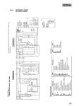
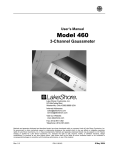
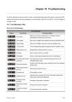
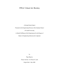
MN-2091U Series User’s Manual
(Version 1.0)
Distributed Motionnet Single-axis Universal Motion Control Module
MN-2091U Series Motion Control Module
The MN-2091U and MN-2091U-T are used to expand the number of axes for distributed motion
control on a Motionnet field bus. These extension slave modules are serially connected to the
controller using a simple and affordable Cat.5 LAN cable, and one serial line can support up to
64 single-axis modules. The 26-pin HD D-Sub connector can be used to easily connect with
various servo drivers and stepper drivers. ICP DAS also provides a variety of cables suitable for
a range of brands of servo drivers, which further reduces the amount of wiring required between
the drivers and the controller, making this an ideal solution for highly integrated machine
automation applications.
This manual mainly describes the signal definition and instruction of operation. The content is
divided into 6 parts: 1. Dimensions, 2. Internal circuit, 3. I/O Signal connectors, 4. Switch setting,
6. LED function description.
1. Dimensions of MN-2091U
Dimension of MN-2091U
ICP DAS
1
MN-2091U Series User’s Manual Rev1.0 2015/08/07
2. Internal Circuit of MN-2091U Series
n
Pulse Output
The pulse output signals are located at pin #5, #6, #23 and #24 of CNM1. Thes signals are
differential line Driver output and the maximum output current of each pin is 20mA. The
connection can be Differential Line Driver or Single Ended Current Sinking depending on
external device.
1. Differential Line Driver connection:
5V_o
+3.3V
P+ / N+
2631
P- / NCW/CCW
EGND
EGND
Inside of Module
2. Single Ended Current Sinking connection:
5V_o
(On CNIO1)
P+
N+
2631
PN-
EGND
EGND
Inside of Module
ICP DAS
Motor Driver
2
MN-2091U Series User’s Manual Rev1.0 2015/08/07
n
Encoder Pulse Input
The encoder pulse input signals are located at pin #7, #8, #16, #17, #25 and #26 of CNM1. These
signals are high speed photo-coupler input with internal resistor of about 550 Ohms and the
suggested input operating current is about 1.6~8mA. As a result, the suggested input voltage
should be within 2.2V~5.5V.
A+/B+/Z+
A/B/Z
2.2V~5.5V
A-/B-/ZFrom Encoder
Inside of Module
The connection can be Differential Line Driver or Open Collector depending on external device.
1. Differential Line Driver connection: Direct connection is possible
A+/B+/Z+
A/B/Z Phase
A-/B-/Z-
Motor Driver
Inside of Module
2. Open Collector: External resistor is required
VPP
A+/B+/Z+
EA/EB/EZ
R
VPP
R
+5V
0 Ohm
+12V
2.2K Ohm
+24V
5.1K Ohm
A-/B-/ZA/B/Z Phase
EGND
Inside of Module
ICP DAS
3
Motor Driver
MN-2091U Series User’s Manual Rev1.0 2015/08/07
n
Position Compare Trigger Output
The position compare trigger output signal is located at pin #4 of CNIO1. This signal is high
speed photo-coupler output and the maximum output current is 40mA. This signal equipped with
a protection diode and a internal pull high resistor of about 1k Ohms to 5V. It can be used to
directly drive either a TTL input or a 24V NPN input.
5V_o
1k
Ohm
+3.3V
CMP
Pulse
EGND
Inside of Module
n
Digital Input
The digital input signals including INP, RDY, ALARM on CNM1 and LMT+/-, HOME, SD,
EMG on CNIO1. These signals are low speed 24V NPN photo-coupler input. Please refer to
figure below for detailed connection information.
NPN Connection
Internal Circuit
E24V
24V
Power
Source
DI
Switch
ICP DAS
Control
Circuit
4.7 k Ohm
4
MN-2091U Series User’s Manual Rev1.0 2015/08/07
n
Digital Output
The digital output signals including SRV_ON, RESET and ERC on CNM1. These signals are
open collector output of low speed photo-coupler with internal flywheel diode and the maximum
output current of each is 50mA. Please refer to figure below for detailed connection information.
NPN Connection
Internal Circuit
E24V
Internal
Power
DO
24V
Power
Source
N.O.
COM
N.C.
50 mA
Max.
Control
Circuit
EGND
ICP DAS
5
MN-2091U Series User’s Manual Rev1.0 2015/08/07
3. I/O Signal connectors of MN-2091U series
n
CNM1 (Female HD D-Sub 26 pin)
This connector contain the commonly used control singals and I/O signals to the servo driver.
ICP DAS provide various cables for easily snap-on connection between different servo drivers
and the MN-2091U series.
No
Name
1 SRV_ON
2
INP
3
ERC
4
RDY
5
P6
P+
7
A8
A+
9
N.C.
I/O
Out
In
Out
In
Out
Out
In
In
N.C.
No
10
11
12
13
14
15
16
17
18
Name
I/O No Name
I/O
RESET
Out
19 EMG
Out
ALARM
In
20
RSV
E-PWR
PWR 21 E-GND
Out
E-GND
PWR 22 E-GND
Out
N.C.
N.C. 23
NOut
AGND
GND 24
N+
Out
BIn
25
ZIn
B+
In
26
Z+
In
N.C.
N.C.
Note: Do not use signals marked as “N.C”
Table below shows the internal I/O connection when using different cable to connect with
respective servo driver:
ICP DAS
6
MN-2091U Series User’s Manual Rev1.0 2015/08/07
CNM1
Pin No. Signal Name
Connected to
Mitsubishi
MELSERVO-J3/J4
Yaskawa
Sigma-II/III/V
CA26-MJ3-xx 50pin
CA26-YSV-xx 50pin
Pin No. Signal Name Pin No.
Signal Name
11
ALARM
Motion ASIC
48
ALM
31
ALM+
2
INPOS
Motion ASIC
24
INP
25
/COIN+
4
RDY
Motion ASIC
49
RD
29
/S-RDY+
10
RESET
Motion ASIC
19
RES
44
/ALMRST
3
ERC
Motion ASIC
41
CR / SP1
14
/CLR
20
RSV
CNIO1
--
Reserved
--
Reserved
1
SRV_ON
Motion ASIC
15
SON
40
/S-ON
21
E-GND
EGND
43
LSP
42
P-OT
22
E-GND
EGND
44
LSN
43
N-OT
19
EMG
CNIO1 and
Motion ASIC
42
EMG
x
N.C.
12
E-PWR
CNIO1
20
DICOM
47
+ 24VIN
13
E-GND
CNIO1
47
DOCOM
26
/COIN-
13
E-GND
--
--
30
/S-RDY-
13
E-GND
--
--
32
ALM-
15
AGND
3
LG
6
SG
28
LG
10
SG
CNIO1
Note
ICP DAS
--
7
To use the CLR (clear)
function, SG signal on the
servo driver should be
connected
to
E-GND
externally.
MN-2091U Series User’s Manual Rev1.0 2015/08/07
CNM1
Pin No.
11
Signal
Name
Panasonic MINAS A4/A5
Fuji FALDIC-W,
ALPHA5 Smart
CA26-PA4-xx 50pin
CA26-FFW-xx 26pin
Connected to Pin No.
ALARM Motion ASIC
Pin Name
Pin No.
Pin Name
37
ALM+
17
OUT3 (ALMb)
2
INPOS
Motion ASIC
39
COIN+ / AT-SPEED+
16
OUT2 (PSET)
4
RDY
Motion ASIC
35
S-RDY+
15
OUT1 (RDY)
10
RESET
Motion ASIC
31
A-CLR
3
CONT2 (RST)
3
ERC
Motion ASIC
30
CL
5
CONT4 (CR)*
20
RSV
CNIO1
--
Reserved
--
Reserved
29
SRV-ON
2
CONT1 (RUN)
1
SRV_ON Motion ASIC
21
E-GND
EGND
9
CCWL
x
N.C.
22
E-GND
EGND
8
CWL
x
N.C.
19
EMG
CNIO1 and
Motion ASIC
33
INH
4
CONT3 (EMG)*
12
E-PWR
CNIO1
7
COM+
1
P24
13
E-GND
38
COIN- / AT-SPEED-
14
M24
13
E-GND
34
S-RDY-
--
--
13
E-GND
36
ALM-
--
--
13
E-GND
41
COM-
--
--
13
GND
26
M5
15
GND
13
M5
17
GND
--
--
15
AGND
Note
ICP DAS
CNIO1
CNIO1
For A4 servo driver, PrNo.40
should be set to “1”
(the default value is “0”)
For A5 servo driver, Pr0.05
should be set to “1”
(the default value is “0”)
8
Please refer to the user’s
manual of servo driver to
modify the setting below
a. Set CONT4 as “7”
(deviation clear)
b. Set CONT3 as “5”
(EMG)
MN-2091U Series User’s Manual Rev1.0 2015/08/07
CNM1
Delta ASDA-A2
Delta ASDA-B2
CA26-DAA2-xx 50pin
CA26-DAB2-xx 44pin
Pin No.
Signal
Name
Connected to
Pin No.
Pin Name
Pin No.
Pin Name
11
ALARM
Motion ASIC
28
DO5+ (ALRM)
28
DO5+ (Alarm)
2
INPOS
Motion ASIC
1
DO4+ (TPOS) /
(BRKR)
1
DO4+ (TPOS) /
(BRKR)
4
RDY
Motion ASIC
7
DO1+ (SRDY)
7
DO1+ (SRDY)
10
RESET
Motion ASIC
33
DI5- (ARST)
33
DI5- (ARST)
3
ERC
Motion ASIC
10
DI2- (CCLR) /
(TRQLM)
10
DI2- (CCLR) /
(TRQLM)
20
RSV
CNIO1
--
Reserved
--
Reserved
1
SRV_ON
Motion ASIC
9
DI1- (SON)
9
DI1- ( SON)
21
E-GND
EGND
31
DI7- (CCWL)
31
DI7- (CCWL)
22
E-GND
EGND
32
DI6- (CWL)
32
DI6- (CWL)
19
EMG
CNIO1 and
Motion ASIC
30
DI8- (EMGS)
30
DI8- (EMGS)
12
E-PWR
CNIO1
11
COM+
11
COM+
13
E-GND
6
DO1-
6
DO1-
13
E-GND
26
DO4-
14
COM-
13
E-GND
27
DO5-
26
DO4-
13
E-GND
49
COM-
27
DO5-
44
GND
19
GND
19
GND
12
GND
15
AGND
Note
ICP DAS
CNIO1
CNIO1
Digit D of P1-00 (source
of pulse command) must
be set as “1” (line driver)
9
Digit D of P1-00 (source of
pulse command) must be set
as “1” (line driver)
MN-2091U Series User’s Manual Rev1.0 2015/08/07
n CNIO1 (Dual row 10 pin removable terminal block)
These connectors contain the input signal of mechanical switch (LMT+/-, HOME, Slow Down),
Emergency Stop input and Position Compare Trigger output. The main power of this module is
also connected via this connector. Table below shows the detailed description of these signal.
Left
No Name
I/O
11 HOME
In
12
SD
In
Right
Note
No
NPN home input signal
(N.C. or N.O. are 1
software selectable)
NPN slow down input
signal (N.C. or N.O. are 2
software selectable)
13 EGND GND GND of external power
14
5V_o
15 AGND
16
17
18
19
20
FGND
EGND
EGND
E24V
E24V
ICP DAS
PWR
--
-GND
GND
PWR
PWR
3
5V power output (*see
4
note)
Directly connected to the
internal signal ground of
servo
driver.
Not 5
connected to any internal
circuit of this module
Name
I/O
LMT-
In
LMT+
EMG
CMP
RSV
Note
NPN negative limit input
signal (N.C. or N.O. are
selectable by SW2)
NPN positive limit input
In signal (N.C. or N.O. are
selectable by SW2)
NPN emergence stop
In
input signal (N.C. only)
Position compare trigger
Out
output
Directly connected to
pin#20 of CNM1. These
-- signal is reserved and not
connected to any internal
circuit of this module
Frame ground
6
-GND Frame ground
GND of external power
7 EGND GND GND of external power
GND of external power
8 EGND GND GND of external power
24V external power input 9 E24V PWR 24V external power input
24V external power input 10 E24V PWR 24V external power input
*Note: The maximum outpu current of 5V_o is 200mA
10
MN-2091U Series User’s Manual Rev1.0 2015/08/07
n RJ1 (RJ45 phone jack, only available in MN-2091U)
RJ1 is the snap in connector for Motionnet communication signals. Table below shows the
detailed description of these signal.
No
1~2
Name
N.C.
I/O
-
Note
-
3
Data+
I/O
Positive line of the differential
communicaiton signal pair
4~5
N.C.
-
6
Data−
I/O
7~8
N.C.
-
Negative line of the differential
communicaiton signal pair
-
n CN1 (5-pin Removable Terminal block, Pitch 5.08 , only available in MN-2091U-T)
CN1 is the screw terminal for Motionnet communication signals. Table below shows the detailed
description of these signal
ICP DAS
No
Name
I/O
Note
1
Data+
I/O
Positive line of the differential
communicaiton signal pair
2
Data−
I/O
Negative line of the differential
communicaiton signal pair
3
FGND
GND
Frame Ground
4
Data+
I/O
Positive line of the differential
communicaiton signal pair
5
Data−
I/O
Negative line of the differential
communicaiton signal pair
11
MN-2091U Series User’s Manual Rev1.0 2015/08/07
4. Switch Setting
n SW3
This switch is used to set the on board termination resistor. The on board termination resistor is
enabled when the switch is set to “ON”. Please be sure to enable the termination resistor only on
the last slave module of each line.
n SW1
Users can set the slave address of this module. Please refer below for detailed description.
Position
Name
1
A0
2
A1
3
A2
4
A3
5
A4
6
A5
ICP DAS
2
3
4
5
A1
A2
A3
A4
6
A5
1
A0
ON
Function
Description
Address
Setting
Every slave module should be assigned a unique address in
a Motionnet communication line and up to 64 slave
modules can be connected in one line. A0 is the least
significant (represent ‘1’ when it is set to ON) while A5 is
the most significant (represent ‘32’ when it is set to ON)
12
MN-2091U Series User’s Manual Rev1.0 2015/08/07
n SW2
Clear
EL_NC
2
3
4
SPD1
Keep
EL_NO
Speed
1
SPD0
Users can set the communication speed, the action of watch dog timer and the polarity of limit
switch of this module . Please refer below for detailed description.
ON
Position
1
Name
Function
SPD0
Speed
Selection
2
3
4
ICP DAS
SPD1
Description
Every slave module should use the same communicaiton
speed as the one set in the master card in a Motionnet
communication line for proper operation. Table below
shows the setting of communicaiton speed.
SPD0
SPD1
Communication Speed
OFF
OFF
20 Mps (default)
ON
OFF
10 Mbps
OFF
ON
5 Mbps
ON
ON
2.5 Mbps
Clear /
Keep
Watch
Dog
Timer
Setting
This bit is used to set the action when the WDT expired
(expire time is 20 ms).
Keep: All output will be holded (default)
Clear: All output will be cleared
EL_NC /
EL_NO
Limit
Switch
Setting
This bit is used to set the polarity of LMT+ and LMTon CNIO1
EL_NO: Normally open or Form A contact (default)
EL_NC: Normally closed or Form B contact
13
MN-2091U Series User’s Manual Rev1.0 2015/08/07
5. LED function description
The LEDs are used to indicate meaningful status. Please refer below for the detailed description
of LEDs
l
LMT – (Red):
It shows the minus end-limit signal of motion control on the machine. The minus end-limit
signal of motion axis is to decide the end point of minus moving. If this signal is on, the
LED will be turned on.
l
HOME (Yellow):
It shows the home signal of motion control on the machine. The LED will be turned on
when the motion control is moved to the home signal.
l
LMT + (Red):
It shows the plus end-limit signal of motion control on the machine. The plus end-limit
signal of motion axis is to decide the end point of plus moving. If this signal is on, the LED
will be turned on.
l
SD (Slow Down, Yellow):
It shows the slow down signal of motion control on the machine. The LED will be turned on
when the motion control is moved to the slow down signal.
l
EMG (EMG OK, Green):
It shows the state of EMG signal of motion module (on CNIO1). The motion module can
driver the motors only when this LED is turned on.
l
PWR (Power OK, Yellow)
It shows the status of internal power of this module. This LED will be turned on when the
power is good.
l
ERR (Communication Error, Red)
This LED will be turned on when the slave module receives an error frame such as a CRC
error which means the the communication quality has been influenced by external noise.
l
LNK (Link, Green)
This LED will be turned on when the communication is successfully established.
l
TER (Terminator On, Yellow)
It shows the status of on board termination resistor. This LED will be turned on when the
termination resistor is enabled.
6. Rivision History
Rev 1.0
ICP DAS
2015/08/07
Initial version
14
MN-2091U Series User’s Manual Rev1.0 2015/08/07