1
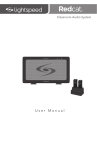
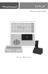
CH A PWR CH B Classroom Audio System User Manual IMPORTANT SAFETY INSTRUCTIONS 1. 2. 3. 4. 5. 6. 7. Read these instructions. Keep these instructions. Heed all warnings. Follow all instructions. Do not use the apparatus near water. Clean only with dry cloth. Do not block any ventilation openings. Install in accordance with the manufacturer’s instructions. 8. Do not install near any heat sources such as radiators, heat registers, stoves, or other apparatus (including amplifiers) that produce heat. 2 9. Do not defeat the safety purpose of the polarized or grounding-type plug. A polarized plug has two blades with one wider than the other. A grounding-type plug has two blades and a third grounding prong. The wide blade or the third prong is provided for your safety. If the provided plug does not fit into your outlet, consult an electrician for replacement of the obsolete outlet. 10. Protect the power cord from being walked on or pinched particularly at plugs, convenience receptacles, and the point where they exit from the apparatus. IMPORTANT SAFETY INSTRUCTIONS CONT’D 11. Only use attachments/ accessories specified by the manufacturer. 12. Use only with a cart, stand, tripod, bracket or table specified by the manufacturer, or sold with the apparatus. When a cart is used, use caution when moving the cart/ apparatus combination to avoid injury from tip-over. 13. Unplug this apparatus during lightning storms or when unused for long periods of time. 14. Refer all servicing to qualified service personnel. Servicing is required when the apparatus has been damaged in any way, such as power-supply cord or plug is damaged, liquid has been spilled or objects have fallen into the apparatus, the apparatus has been exposed to rain or moisture, does not operate normally, or has been dropped. 15. When the mains plug or appliance coupler is used as the disconnect device, it shall remain readily operable. 16. Please keep the unit in a good ventilation environment. 3 TABLE OF CONTENTS 4 SECTION 1: Overview 7 9 12 13 14 16 18 22 System Components and Unpacking Optional Components Front Panel Indicators Top Panel Controls Side Panel Controls and Connections Rear Panel Controls and Connections REDMIKE Controls and Connections Cradle Charger Controls and Connections SECTION 2: Set-up & Use 24 25 27 30 31 35 Step 1. Determine Set-up Location 1A. To Set-Up on Table Top 1B. To Set-Up Mounted on a Wall 1C. Wall Mounting Locations Step 2. Audio Integration Step 3. Connecting the Power Supply TABLE OF CONTENTS CONT’D SECTION 2: Set-up & Use Cont’d 36 38 41 43 4. Charging the REDMIKE Operating the REDMIKE Output to Assistive Listening Device (ALD) Using REDMIKE as Wireless Audio Link SECTION 3: Optional Accessories 46 49 49 52 52 53 54 56 58 Optional REDMIKE VC Controls and Connections REDMIKE VC: Charging REDMIKE VC: Intial Set-up REDMIKE Share: Controls and Connections REDMIKE Share: Charging REDMIKE Share: Initial Set-up Initial Set-up: Optional IRMC Media Connector Optional IRMC Media Connector Audio Integration Optional Accessories 5 TABLE OF CONTENTS CONT’D 6 SECTION 4: Troubleshooting 59 62 Common Problems and Solutions Tips to Obtain Optimum Audio Performance Output to Assistive Listening Device (ALD) Using the REDMIKE to Amplify External Audio Equipment SECTION 5: Warranty, Safety & Specifications 63 65 69 Five-Year Limited Warranty Safety Warnings and Certifications System Specifications SECTION 1: OVERVIEW SYSTEM COMPONENTS AND UNPACKING The standard configuration of the REDCAT® will contain: CH A PWR CH B REDCAT® Infrared Receiver/Amplifier with Table Stand and Power Supply 7 SYSTEM COMPONENTS AND UNPACKING CONT’D The standard configuration of the REDCAT will contain: Charging Cradle and Power Supply 8 REDMIKE® Classroom Microphone OPTIONAL COMPONENTS Optional equipment which may be part of your REDCAT system: REDMIKE® VC Volume Control Microphone REDMIKE® Share Handheld Mic & Charger Cable 9 STANDARD COMPONENTS Standard Components 10 RC2 REDCAT all-in-one receiver/amplifier/speaker with power supply 24V-1.75-NA Power supply for REDCAT RMT2 REDMIKE classroom microphone with lavaliere cord and rechargeable AA battery NH2A27 Lightspeed AA rechargeable sensing battery (for REDMIKE) AC-RMLC2 Lavaliere cord for REDMIKE BC-RMCC REDMIKE cradle charger 5V-1.0-NA Cradle charger power supply OPTIONAL COMPONENTS Optional Components RMV2 REDMIKE VC microphone with battery RMS2 REDMIKE Share handheld microphone with battery pack NH2APK NiMH rechargeable battery pack for REDMIKE Share LT71 LightMic microphone with batteries IRMC2 Infrared media connector with cables and power supply AC-WMKRC2 REDCAT wall mounting kit includes screws, wall anchors, security clip and extra RC feet NH1 AA NiMH rechargeable battery (LT71) 11 FRONT PANEL INDICATORS 1. POWER ON INDICATOR: The power LED will glow Blue when power is applied. 2. CH A & CH B: Illuminate Red when the audio for the corresponding microphone is received. 12 2 2 1 CH A PWR CH B TOP PANEL CONTROLS 1. CHANNEL A VOLUME: Controls the volume level of the microphone set to Channel A. 2. CHANNEL B VOLUME: Controls the volume level of the microphone set to Channel B. 2 1 CH A MIN MICROPHONE CH B MAX MAX MIN 13 SIDE PANEL CONTROLS AND CONNECTIONS 1. TONE CONTROL: Adjusts the audio level for optimum sound quality. 2. AUDIO INPUT VOLUME CONTROL & INPUT JACK: 3.5mm stereo connector for connecting classroom audio sources to the REDCAT. Controls the volume level of the audio input from the connected audio source. 3. AUDIO OUTPUT VOLUME CONTROL & INPUT JACK: 3.5mm stereo connector for connecting to an assisted listening device (ALD) or to a computer for recording. Controls the volume level of the audio output. 14 4. POWER SWITCH: This switch is used to turn the REDCAT ON or OFF. The front panel Blue LED lights when power is ON. 5. DC POWER INPUT JACK: Plug the power supply (24V/1.75A) into this jack. SIDE PANEL CONTROLS CONT’D 1 2 3 4 5 15 REAR PANEL CONTROLS AND CONNECTIONS 1. CARRYING INSET: Cutaway grip for moving or carrying the REDCAT. 2. CABLE MANAGEMENT AND STRAIN RELIEF 16 REAR PANEL CONTROLS AND CONNECTIONS CONT’D 1 Testing Purposes Only 17 REDMIKE CONTROLS AND CONNECTIONS 1. POWER BUTTON: Press this button to turn the REDMIKE ON, press again to turn it OFF (mute). 2. POWER/LOW BATTERY INDICATOR: A BLUE light indicates the REDMIKE is on and fully charged. A RED light indicates a charge is needed. 3. Battery Compartment: To access the battery compartment, slide the door downward. The battery should only be replaced by a Lightspeed AA rechargeable sensing battery (part # NH2A27). 18 4. YELLOW PROTECTIVE TAB: Slide the battery compartment door open to remove this disposable protective tab before use. NOTE: do not attempt to remove the tab without first opening the compartment door, as it may tear, leaving fragments. Note: REDMIKE microphones are shipped with batteries installed. Charge the microphone overnight before using. Slide battery door o p Remove tab before en us e 4 1 REDMIKE CONTROLS CONT’D 2 3 19 REDMIKE CONTROLS CONT’D 5. AUDIO/MICROPHONE INPUT: Use this input to plug in a laptop, MP3 player or other audio source to wirelessly transmit audio to be played through the system. Alternatively, an external microphone can be connected. 6. CHANNEL SELECT SWITCH (CH A/B): This switch allows for selection between Channel A or B. If you are using a single microphone, we recommend using Channel A. 7. Charger Contacts (+ -): These contacts interface with the charging tabs in the BCRMCC cradle charger for daily charging. Simply place the REDMIKE in the charger. 20 8. Group Designation: G1= Group 1 frequencies 2.06/2.54 MHz G2= Group 2 frequencies 3.20 / 3.70 MHz REDMIKE CONTROLS CONT’D 5 6 8 7 21 CRADLE CHARGER CONTROLS AND CONNECTIONS 1. CHARGE INDICATORS: The light glows RED while the REDMIKE is charging. When fully charged, the light will glow GREEN. A blinking RED light indicates that no battery is sensed, (REDMIKE Yellow Protective Tab may not have been completely removed—see page 18, item 4.) A blinking Green LED means a non-Lightspeed battery has been installed (possibly an alkaline battery). 22 2. DC POWER INPUT: Connect the 5V/1.0A DC power supply here. 3. OPTIONAL CHARGING PORT: Plug the charging cord for the optional LT71 or the REDMIKE Share microphones here. CRADLE CHARGER CONTROLS AND CONNECTIONS CONT’D 2 1 3 23 SECTION 2: SET-UP & USE 1. DETERMINE SET-UP LOCATION The REDCAT is shipped with feet to stand on a cabinet or tabletop. Alternatively, the feet can be used as the wall mount bracket. Advantages of either include: 24 Tabletop (recommended): Wall-mount: UÊ6ÀÌÕ>ÞÊÊÃiÌÕ«ÊÌi UÊÀiÊ«iÀ>iÌÊÃiÌÕ« UÊÀi>ÌiÀÊyiÝLÌÞÊÌÊÛiÊÌÊ`vviÀiÌ locations UÊÀi>ÌiÀÊÃiVÕÀÌÞ 1A. TO SET-UP ON TABLE-TOP First, consider that the REDCAT should be placed within within 7 feet of an electrical outlet and on a surface about 3-6 feet off the ground. Next, find a location as far away as possible from the teacher who will be using the mic. The best place is against the wall opposite where the teacher will be speaking. If this is not possible, other good locations are along either wall next to the teacher or in a corner. Avoid placing the REDCAT next to where the teacher instructs. Putting the REDCAT in close proximity to the teacher’s mic can result in feedback. 25 1A. TO SET-UP ON TABLE-TOP CONT’D Best placement Good placement 26 Avoid! 1B. WALL MOUNTING PROCEDURE For wall-mounting the REDCAT System: To hang the system on a wall, drill these four holes. REQUIRED MATERIALS UÊ Drill Bit: 1/4” Drill Bit UÊ Anchors: Needed for mounting on drywall UÊ Screws: wood screws or screws appropriate for anchors LOCATION UÊ Find a location as far away as possible from the teacher who will be using the mic. The best place is centered on the long wall opposite the teacher. Avoid placing the REDCAT on any wall close to where the teacher usually stands to instruct the class. Having the teacher’s mic too close to the REDCAT can result in feedback. MOUNT UÊ Èn½Ê>LÛiÊÌ iÊyÀ°ÊV>ÌiÊÜÌ ÊÇÊvÌÊvÊ>ÊÜ>Ê outlet. 27 1B. WALL MOUNTING PROCEDURE CONT’D INSTRUCTIONS 1. Level template and tape to wall 2. Mark position of drill holes on wall 3. Drill pilot holes 4. Insert anchors 5. Insert screws through the REDCAT feet into the anchors 6. If using optional security bracket, mount on wall using the provided screws and anchors 7. Slide the REDCAT onto the wall mounted feet 28 OR 1B. WALL MOUNTING PROCEDURE CONT’D 29 1C. WALL MOUNTING LOCATIONS Best placement Good placement 30 Avoid! 2. AUDIO INTEGRATION The next step in setting up your REDCAT system is to connect it to the other elements of your audio system. Audio systems have varying elements – you may have a computer, television, DVD/VCR player, a visual projection system or other devices. In this section you will find instructions on how to connect an external audio device like a TV, VCR, DVD, MP3 or computer directly into the REDCAT. 31 2. AUDIO INTEGRATION CONT’D Projector Projector Audio Input The REDCAT has one audio input with volume control for connecting to classroom audio sources. Use a 3.5 mm to 3.5 mm patch cable (MSC3535) to connect a computer, iPod, iPad, etc. audio sources. Teacher’s REDMIKE VGA Out Audio Out IR Transmission Teacher’s REDMIKE VGA Out Audio Out Audio In 32 Audio In CH A PWR CH B CH A PWR CH B IR Transmission REDCAT Teacher’s REDMIKE 2. AUDIO INTEGRATION CONT’D 1. Turn the Audio Input volume on the REDCAT all the way down. 2. Connect a patch cable (not included) from the audio source into the Audio IN jack on the side of the REDCAT. 3. With both the REDCAT and audio source power on, adjust the volume control until the desired level is achieved. NOTE! Be careful not to set the volume too high, as this can distort the speaker and potentially cause damage. 33 2. AUDIO INTEGRATION CONT’D 34 3. CONNECTING THE POWER SUPPLY 1. Locate the power supply and AC power cord. Connect the AC power cord into the DC power supply. Make sure the AC Power cord is inserted all the way into the power supply. 2. Insert the DC connector into the “DC POWER INPUT” jack on the side of the REDCAT and plug the other end into an electrical outlet. 35 4. CHARGING THE REDMIKE Before use, the REDMIKE should be charged. It will take 8-9 hours for the REDMIKE to obtain a full charge. A fully charged REDMIKE will last for over 7 hours of use. If microphones are used daily, they should be kept in the cradle. A red light on the charging cradle indicates the REDMIKE is charging. A green light indicates that charging is complete and a full charge has been reached. A blinking light indicates a charging or sensing error. See Troublshooting section for more information. REDMIKE incorporates alkaline protection into the microphone design. Always use a Lightspeed rechargeable sensing battery. Replacement AA 36 NiMH batteries may only be purchased through Lightspeed Technologies (part # NH2A27). 4. CHARGING THE REDMIKE CONT’D 1. Plug power cord into the cradle charger and then plug the AC end into an electrical outlet. NOTE: The power supply for countries outside the USA and Canada has interchangeable power plug adapters. Select the correct adapter for your country. 2. Ensure that the REDMIKE is turned OFF. 3. Place the REDMIKE into the cradle. The LED on the cradle will glow RED indicating charging has started. When the REDMIKE is fully charged the LED on the cradle charger will change to GREEN. 37 5. OPERATING THE REDMIKE Once the REDMIKE is charged, follow these steps to set it up for use. 1. Push the REDCAT power switch to the ON position. 2. Remove the REDMIKE from the charging cradle and turn it on. The red IR LED (CH. A or CH. B) on the REDCAT will light to indicate a signal is being received. 3. Slip the REDMIKE with lanyard around the neck and position the top of the microphone just below the collarbone. The REDMIKE should be centered on the plastic insert in the lanyard. 4. Slowly increase the CH. A/B volume up to the “silver” section of the dial. This designates normal volume range in the classroom. 38 5. While speaking in a normal voice, fine-tune the volume up or down. Proper volume level should be as follows: UÊ Your voice should be clearly heard by another person on the other side of the room. UÊ You should barely be able to hear your own voice. UÊ There should not be any audio “feedback” or squealing outside of 2-3 feet (if there is, turn the volume down slightly). REMEMBER: This equipment supplements the user’s voice so they are able to speak in a conversational tone. Having the volume set too high will result in feedback and listener fatigue. 5. OPERATING THE REDMIKE CONT’D 6. Once initial volume level is set, walk around the room and listen for audio dropout and overall audio quality. 7. If a second REDMIKE was purchased, repeat steps 2-5. CH A MIN MICROPHONE CH B MAX MAX MIN 39 5. OPERATING THE REDMIKE CONT’D 40 OUTPUT TO ASSISTIVE LISTENING DEVICE (ALD) 1. Turn the Audio (ALD) Out volume control on the REDCAT side panel all way the down. 2. Determine the size and type of audio input jack on the device as many manufacturers’ products differ in connector size and shape. The Lightspeed LES-370 Personal FM System requires a 3.5mm to 3.5mm patch cable (part# MSC3535, not included). receiver to maximum output. NOTE: This is to set the maximum allowable signal from the REDCAT. 5. With the REDCAT and ALD turned on, speak into the REDMIKE and slowly adjust the AUDIO OUT volume control until the appropriate audio level is attained in the ALD’s receiver headphones. 3. Connect a patch cable from the ALD’s microphone jack or AUX input to the 3.5mm audio jack labeled “AUDIO OUT” on the side of the REDCAT. 4. Adjust the volume control on the ALD’s 41 OUTPUT TO ALD CONT’D 42 USING REDMIKE AS WIRELESS AUDIO LINK The REDMIKE includes a 3.5mm audio input jack to connect to an audio source like a laptop or MP3 player. The REDMIKE will transmit the audio signal to be played through the system. To determine which REDMIKE is set to Channel B, you can look at the switch on the back of the mic or speak into one of the microphones. If your system includes two REDMIKEs, we recommend using Channel B (student mike) to amplify the external audio equipment so the teacher’s volume on the Channel A (teacher mike) does not have to be adjusted. 43 USING REDMIKE AS WIRELESS AUDIO LINK CONT’D 1. Plug your external audio equipment (for example, laptop), into the input on the REDMIKE labeled “INPUT” using a 3.5mm patch cable. AUDIO OUTPUT 44 AUDIO INPUT USING REDMIKE AS WIRELESS AUDIO LINK CONT’D 2. Adjust the volume of the selected mic channel to achieve desired loudness. CH A MIN MICROPHONE CH B MAX MAX MIN 45 SECTION 3: OPTIONAL ACCESSORIES OPTIONAL REDMIKE VC (VOLUME CONTROL) CONTROLS AND CONNECTIONS 46 OPTIONAL REDMIKE VC CONTROLS CONT’D 1. POWER/MUTE BUTTON 2. POWER/LOW BATTERY INDICATOR: A BLUE light indicates the REDMIKE VC is on and fully charged. A RED light indicates a charge is needed. 5. AUDIO/MICROPHONE INPUT: Use this input to plug in a laptop, MP3 player or other audio source to wirelessly transmit audio to be played through the system. Alternatively, an external microphone can be connected. 3. Battery Compartment: To open, slide the door downward. The battery should only be replaced by a Lightspeed AA rechargeable sensing battery (part # NH2A27). 6. CHANNEL SELECT SWITCH (CH A/B): Use this to choose Channel A or B. If you are using a single microphone, we recommend using Channel A. 7. Volume controls (up - down) 4. YELLOW PROTECTIVE TAB: Slide the battery compartment door and remove this disposable protective tab before use. 8. Charger Contacts (+ -): These contacts interface with the charging tabs when the REDMIKE VC is placed in the BC-RMCC cradle charger. 47 5 Slide battery door o p Remove tab before en us e 8 48 4 1 OPTIONAL REDMIKE VC CONTROLS CONT’D 6 2 7 3 REDMIKE VC : CHARGING Before use, the REDMIKE VC should be charged. See page 38 and follow the same instructions for the REDMIKE. REDMIKE VC : INITIAL SET-UP See page 36 and follow the same instructions for the REDMIKE to setup the REDMIKE VC. NOTE: A nominal volume level must be set on the REDCAT before adjusting controls on the REDMIKE VC. The teacher can now use the controls on the REDMIKE VC to adjust the volume level from anywhere in the room. The microphone volume control has 4 steps up and 4 steps down from the mid point (9 levels total). 49 REDMIKE SHARE: CONTROLS AND CONNECTIONS 1. POWER SWITCH 2. POWER/CHARGE INDICATOR: this light glows blue when turned on and turns off to indicate low battery level. When charging, the light glows red. 3. AUDIO INPUT: plug a laptop, MP3 player or other audio device into this jack to wirelessly transmit the audio signal to be played through the system. 50 4. CHANNEL SELECT SWITCH (CH A/B): Located in the battery compartment, this switch is set to Channel B at the factory. 5. CHARGER INPUT: Plug the charging cable from the REDMIKE cradle charger into this jack. REDMIKE SHARE: CONTROLS AND CONNECTIONS CONT’D 2 3 1 4 5 51 REDMIKE SHARE: CHARGING 1. Ensure the REDMIKE share is turned OFF. 2. Make sure the cradle charger is plugged into a wall outlet. Connect one end of the charging cable into the jack labeled CHARGER on the bottom of the REDMIKE Share. Plug the other end into the charging jack on the rear of the cradle charger. 3. The LED on the microphone will glow RED to indicate charging. 4. Leave the REDMIKE Share plugged in overnight (8-10 hours) to obtain a full charge. 52 REDMIKE SHARE: INITIAL SET-UP 1. Ensure the REDCAT is ON. The blue LED on the front panel will glow. 2. Turn on the REDMIKE Share by sliding the switch to the top position. 3. Grip the barrel in the center section. Avoid covering the infrared emitters just below the microphone grille. This could interrupt signal transmission. REMEMBER: This equipment is designed to supplement and distribute the user’s voice so they are able to speak in a conversational tone. Having the volume set too high will result in feedback and listener fatigue. 4. While speaking in a normal voice, increase the CH. B VOLUME on the REDCAT level until your voice is barely audible. 53 INITIAL SET-UP: OPTIONAL IRMC MEDIA CONNECTOR 1. Turn off the second microphone. The iR Media Connector uses the same channel (channel B) as the optional second microphone (REDMIKE or REDMIKE Share). As a result, they cannot be used simultaneously. If you have a second microphone, turn it off before transmitting audio from the iRMC. NOTE: If you adjust the CH B volume on the classroom audio system, you will also be changing the volume for your second microphone. Return the CH B volume knob to the original position before turning the second microphone back on. 54 2. The iR Media Connector volume is preset for most standard audio signals. If you need to turn the volume up or down, follow this procedure: A. Adjust the volume at the computer, television, or other audio source if possible. INITIAL SETUP: OPTIONAL IRMC MEDIA CONNECTOR CONT’D B. If the audio source does not have a volume control (such as many DVD players) adjust the volume at the iRMC. 3. If the first two options do not give optimum volume level, the last place to adjust the volume is the CH. B Volume on the REDCAT. CH A PWR CH B 55 OPTIONAL IRMC MEDIA CONNECTOR AUDIO INTEGRATION The iRMC is designed to integrate with the REDCAT and multiple audio sources, allowing other instructional technologies to be clearly heard throughout the classroom. 56 Video In OPTIONAL IRMC AUDIO INTEGRATION Video In Projector Projector Projector Projector CONT’D CH A PWR CH B CH A PWR CH B Teacher’s Microphone Teacher’s Microphone VGA Out Audio Out VGA Out Audio Out REDCAT REDCAT Audio In Audio In Video Out Audio Out Video Out Audio Out Video Out DVD/VCR Audio Out Video Out DVD/VCR Audio Out iR Media Connector iR Media Connector 57 OPTIONAL ACCESSORIES Other Optional Accessories 58 RMS2 REDMIKE Share microphone with rechargeable battery pack and charging cable LT71 LightMic with rechargeable batteries and charging cable MC-TK250LTM Noise-canceling headset microphone AC-TCC7 Charging cable for LT71 and REDMIKE Share microphones MSC3535 3.5mm to 3.5mm stereo audio cable NH1 AA Rechargeable battery (for LT71 and REDMIKE Share) SECTION 4: TROUBLESHOOTING COMMON PROBLEMS AND SOLUTIONS Note: Most problems are directly related to low battery power. Please run through the “Battery Check” items first. For remaining troubleshooting, use known good, fully-charged batteries. 59 COMMON PROBLEMS AND SOLUTIONS CONT’D 60 ALL PROBLEMS: Most Problems are related to low battery power. UÊ Ã«iVÌÊÌ iÊL>ÌÌiÀÞÊVÌ>VÌÃ°Ê i>Ê>`Ê>`ÕÃÌÊ if necessary. SOLUTION: Battery Check PROBLEM: Hearing Static UÊ wÀÊL>ÌÌiÀiÃÊ>ÀiÊV >À}i`Ê each night. SOLUTION: Follow these steps to eliminate static. UÊ wÀÊ«À«iÀÊL>ÌÌiÀiÃÊ>ÀiÊÕÃi`°Ê/ iÊ REDMIKE requires the Lightspeed NH2A27 rechargeable sensing battery for proper charging. The REDMIKE Share requires NH2PAK AA rechargeable battery pack. UÊ ÃÕÀiÊ, /ÊÃÊÊ«ÌÕÊV>Ì°Ê/ iÊ REDCAT will cover a 1200 sq. ft. enclosed classroom. UÊ >iÊÃÕÀiÊÌ iÊVÀ« iÃÊ>ÀiÊÌÕÀi`ÊvvÊ while charging so a full charge is attained. Full charge will last over 7 hours. UÊ vÊÌ iÊ«Ì>Ê, Êi`>ÊViVÌÀÊ is in use, set the microphone to Channel A. UÊ ÃÕÀiÊÌ >ÌÊÊÌ iÀÊ,É,Ê Share is operating on the same channel. COMMON PROBLEMS AND SOLUTIONS CONT’D PROBLEM: Low Volume or Feedback SOLUTION: Follow these steps to eliminate low volume or feedback. UÊ ÃÕÀiÊVÀ« iÊÃÊ«ÃÌi`Ê appropriately, just below the collar bone. UÊ /ÕÀÊÌ iÊ, /Ê°Ê wÀÊÌ >ÌÊÌ iÊ*"7,Ê light located on the front panel is on. UÊ wÀÊÃ}>ÊÃÊLi}ÊÀiViÛi`Ê>ÌÊÌ iÊ REDCAT. The IR signal light will be RED indicating a signal is being received. UÊ iVÊÛÕiÊiÛiÊÊÌ iÊ>«wiÀ°ÊvÊÌ iÊ volume is too high, feedback will occur. Adjust accordingly. UÊÊ wÀÊÌ >ÌÊ,ÊÃÊÌÕÀi`Ê°Ê/ iÀiÊ will be a BLUE LED on the microphone to indicate it is powered on. UÊ `ÕÃÌÊÌ iÊÛÕiÊiÛiÊÊÌ iÊL>VÊvÊÌ iÊ optional REDMIKE VC. If you review these instructions and still have questions, write down the serial number and model number of your system and call Lightspeed Technical Services at 800.732.8999, 5 a.m. – 5 p.m., PST. PROBLEM: No Sound From Speaker SOLUTION: Follow these steps to produce sound from speakers. 61 TIPS TO OBTAIN OPTIMUM AUDIO PERFORMANCE UÊÊ-«i>ÊÊ>Ê>ÌÕÀ>ÊÛVi°ÊÊÀ>Ê conversational speech level will provide an adequate signal. It is not necessary to increase the intensity of your voice— the audio system provides adequate amplification (approximately 5 – 10 dB) above ambient room noises. UÊ Û`ÊÜi>À}ÊiÜiÀÞÊÌ >ÌÊ>ÞÊÀÕLÊÀÊLÕ«Ê against the microphone. 62 UÊ /ÕÀÊÌ iÊ,ÊvvÊ`ÕÀ}Ê«ÀÛ>ÌiÊ conversations with a student, parent, or other classroom visitor. You can also cover the LED lens on top of the REDMIKE to block the signal. UÊ ,iV >À}iÊL>ÌÌiÀiÃÊi>V Ê} Ì°Ê7 iÊ recharged nightly, operating time (actual usage) for the transmitters will last through a typical school day. SECTION 5: WARRANTY, SAFETY & SPECIFICATIONS FIVE-YEAR LIMITED WARRANTY Lightspeed Infrared Audio Systems and optional accessories are warranted against malfunction due to defect in materials and workmanship for a period of five (5) years from date of purchase. System components will be repaired or replaced at Lightspeed’s option. Rechargeable batteries and connecting cables are guaranteed for one (1) year. Warranty does not extend to finish, appearance, or malfunctions due to abuse or misuse. Repairs performed by other than Lightspeed Technologies will void this warranty. For warranty service, including return shipping labels, please contact Lightspeed’s Service Department at 800.732.8999 / [email protected]. 1. Warranty on infrared microphones is FIVE (5) YEARS. 2. Warranty on Lightspeed rechargeable batteries, all external cables and wires provided by Lightspeed is one (1) year. 63 FIVE-YEAR LIMITED WARRANTY CONT’D 3. Prepaid shipping labels are provided by Lightspeed factory or an authorized warranty service center for warranty repairs. 4. Warranty does not extend to finish, appearance items, or malfunctions due to abuse or operation other than specified conditions, nor does it extend to incidental or consequential damages. Repair by other than Lightspeed or its authorized service agencies will void this guarantee. Information on authorized service agencies is available from Lightspeed Technologies, Inc. 64 Our Service Department (800.732.8999, 5 a.m. – 5 p.m., PST) will handle all your repair/replacement needs. SAFETY WARNINGS AND CERTIFICATIONS CAUTION RISK OF ELECTRIC SHOCK DO NOT OPEN CAUTION: TO REDUCE THE RISK OF ELECTRIC SHOCK DO NOT REMOVE COVER (OR BACK) NO USER-SERVICEABLE PARTS INSIDE REFER SERVICING TO QUALIFIED PERSONNEL / iÊ} Ì}Êy>à ÊÜÌ Ê>ÀÀÜ i>`ÊÃÞLÊ within an equilateral triangle is intended to alert the user to the presence of uninsulated “dangerous voltage” within the product’s enclosure, that may be sufficient magnitude to constitute a risk of electric shock. The exclamation point within an equilateral triangle is intended to alert the user to the presence of important operating and maintenance (servicing) instructions in the literature accompanying the appliance. 65 SAFETY WARNINGS AND CERTIFICATIONS CONT’D This product is listed to UL standards and requirements for electrical safety by Underwriters Laboratories Inc. This product conforms with the essential requirements of the following European Union Directives: 89/336/EEC, 92/31/EEC, 93/68/ EED, and 2004/108/EC Electromagnetic Compatibility Directives. 66 Lightspeed Technologies launched a formal product recycle program in Europe that complies with the European Union Directive 2002/96/EC on Waste Electrical and Electronic Equipment (“WEEE Directive”). Please visit our website at www.Lightspeed-tek.com for more information. This product is manufactured using lead-free processes and is free of other materials harmful to the environment. It conforms to the most stringent new European guidelines for consumer products (RoHS). This device complies with part 15 of the FCC Rules. Operation is subject to the following two conditions: (1) This device may not cause harmful interference, and (2) this device must accept any interference received, including interference that may cause undesired operation. Changes or modifications not expressly approved by the party responsible for compliance could void the user’s authority to operate this equipment. This equipment has been tested and found to comply with the limits of a Class B Digital Device, pursuant to Part 15 of the FCC Rules. These limits are designed to provide reasonable protection against harmful interference in a residential installation. This equipment generates, uses and can radiate radio frequency energy and, if not installed and used in accordance with the instruction may cause harmful interference to radio communication. However, there is no guarantee that interference will not occur in a particular installation. However, there is no guarantee that interference will not occur in a particular installation. If this equipment does cause interference to radio or television reception, which can be determined by turning the equipment off and on, the user is encouraged to try to correct the interference by one or more of the following measures. UÊ UÊ UÊ UÊ Reorient or relocate the receiving antenna Increase the separation between the equipment and the receiver Connect the equipment into an outlet on a circuit different from that to which the receiver is connected Consult the dealer or an experienced radio/TV technician for help Caution: To maintain the compliance with the FCC’s RF exposure guideline, place Media Connector & TOPCAT at least 20 cm from nearby persons. 67 Ce dispositif est conforme à l’article 15 de la réglementation FCC. Le fonctionnement est soumis aux deux conditions suivantes : (1) ce dispositif ne peut pas causer d’interférence nuisible et (2) ce dispositif doit accepter toute interférence reçue, notamment les interférences pouvant occasionner un fonctionnement non souhaité. Tout changement ou modification n’ayant pas fait l’objet d’une autorisation expresse émanant de la partie responsable de la conformité pourraient entraîner la perte du droit d’usage de l’équipement par l’utilisateur. Cet équipement a été testé et certifié conforme aux restrictions pour les appareils numériques de Classe B, conformément à l’article 15 de la réglementation FCC. Ces restrictions visent à assurer une protection raisonnable contre les interférences nuisibles dans les installations résidentielles. Cet équipement produit, utilise et peut émettre de l’énergie de fréquence radio et, s’il n’est pas installé et utilisé conformément aux instructions, peut causer des interférences nuisibles aux communications radio. Toutefois, rien ne garantit l’absence d’interférences dans une installation particulière. Toutefois, rien ne garantit l’absence d’interférences dans une installation particulière Si cet équipement provoque des interférences avec la réception radio ou télévision - ce qui peut être déterminé en éteignant et en rallumant l’équipement - il est recommandé à l’utilisateur d’essayer de corriger les interférences par l’un des moyens suivants : UÊ UÊ UÊ UÊ 68 En réorientant ou en réinstallant l’antenne de réception En augmentant la distance entre l’équipement et le récepteur En branchant l’équipement à un circuit autre que celui où le récepteur est branché En contactant le revendeur ou un technicien expérimenté en radio/télévision Attention : afin d’assurer la conformité aux exigences de la FCC en matière d’exposition aux RF, placez le Media Connector et le TOPCAT à une distance de 20 cm minimum des personnes les plus proches. SYSTEM SPECIFICATIONS OVERALL SPECIFICATIONS Power Output Amplifier Frequency Response Signal-to-Noise Ratio Dynamic Range Overall Dimensions (W x D x H) Weight 20 Watts 120 Hz – 13 kHz >77 dB > 73 dB 16” x 9.5” x 1.75” (406.4 mm x 241.3 mm x 44.5 mm) 3.23 lbs. (1.5 kg) 69 SYSTEM SPECIFICATIONS CONT’D RECEIVER SPECIFICATIONS 70 Carrier Frequencies (IR) IR Operating Range Receiver Type Receiver Sensitivity 2.06 / 2.54 MHz up to 1200 square feet Superheterodyne 6 µV for 60 dB S/N Image and Spurious Rejection > 70 dB Alternate Carrier Frequencies (iR) 3.20/3.70 MHz SYSTEM SPECIFICATIONS CONT’D TRANSMITTER SPECIFICATIONS REDMIKE and REDMIKE VC Audio Distortion Built-in Microphone Battery Power (1-year warranty) Audio Input Dimensions (W x D x H) Weight <1% Unidirectional Electret 1 AA NiMH Rechargeable Sensing Battery 3.5 mm 0.9” x 1.0” x 3.5” (22.9 mm x 25.4 mm x 88.9 mm) 2.1 oz. (59.5 g) 71 SYSTEM SPECIFICATIONS CONT’D TRANSMITTER SPECIFICATIONS REDMIKE Share Handheld Microphone Audio Distortion Built-in Microphone Battery Power (1-year warranty) Dimensions (W x D x H) Weight 72 <1% Unidirectional Electret 2 AA NiMH Rechargeable 2.25” x 2.25” x 8.75” (57.2 mm x 57.2 mm x 222.3 mm) 7.36 oz. (208.7 g) AC-MNRC2 LI G HT S P E E D T E C H N O L O G I ES 1150 9 SW HE R M A N R O A D / TUA LATI N, O R 9 7 0 6 2 TO L L FREE: 8 0 0 . 7 3 2 . 8 9 9 9 / P H O NE: 5 0 3 . 6 8 4 . 5 5 3 8 / FA X : 5 0 3 . 6 8 4.3197 LIG HTSP E E D - T E K . C O M MN0435US01-0