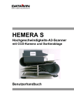
Download User manual Hemera S English Date: 09/2012 | Size: 4
Transcript
E
HEMERA S
High Speed A3 Scanner
with CCD Camera and Sorter
User Manual
Publisher:
DATAWIN GmbH
Etzstraße 37
D-84030 Ergolding
Tel. :+ 49 (0)871-43 05 99 0
Fax: + 49 (0)871-43 05 99 29
Email: [email protected]
Web: http://www.datawin.de
Printed in Germany
Subject to alteration
Windows is a registered trademark of the Microsoft Corporation.
Copyright © DATAWIN GmbH
All rights reserved
This manual is the intellectual property of DATAWIN GmbH.
Unauthorized use, duplication or distribution is prohibited.
Any reproduction of the contents of this manual, in whole or in part, without written permission of DATAWIN
GmbH is forbidden.
Edition August 2012/1.2
DATAWIN GmbH
HEMERA S – User Manual
2
Table of Contents
1
1.1
1.1.1
1.2
1.2.1
1.2.2
1.2.3
1.3
1.3.1
1.3.2
1.3.3
Introduction .................................................................................................... 1-1
About this manual............................................................................................. 1-1
Typographical notes ......................................................................................... 1-1
Information about the packaging....................................................................... 1-2
Unpacking ........................................................................................................ 1-2
Repacking ........................................................................................................ 1-4
Scope of the delivery ........................................................................................ 1-7
Device related safety information...................................................................... 1-8
Conformity ........................................................................................................ 1-8
Precautionary measures for transportation, storage and installation ................. 1-8
Selection of the work site.................................................................................. 1-9
2
2.1
2.2
2.2.1
2.2.2
2.2.3
2.2.4
2.2.5
2.2.5.1
2.2.5.2
2.2.5.3
2.2.5.4
The HEMERA S scanner................................................................................. 2-1
Functional components..................................................................................... 2-1
Document processing – from intake to output ................................................... 2-3
Automatic document intake............................................................................... 2-3
Paper path........................................................................................................ 2-4
Document output .............................................................................................. 2-5
Camera system ................................................................................................ 2-6
Optional components........................................................................................ 2-7
Bar code readers .............................................................................................. 2-7
OMR mark recognition...................................................................................... 2-7
MICR module.................................................................................................... 2-8
Printers............................................................................................................. 2-9
3
3.1
3.2
3.3
3.3.1
3.4
3.4.1
3.4.2
3.5
3.6
Preparing the scanner for operation ............................................................. 3-1
Mains connection data...................................................................................... 3-1
Interfaces.......................................................................................................... 3-1
PC connection .................................................................................................. 3-2
Minimum requirements on the external PC ....................................................... 3-2
Preparation of the scanner ............................................................................... 3-2
Test documents ................................................................................................ 3-2
Printers............................................................................................................. 3-2
Test run ............................................................................................................ 3-2
De-installing the scanner .................................................................................. 3-3
4
4.1
4.2
4.2.1
4.2.2
4.3
4.3.1
4.3.2
Working with the scanner .............................................................................. 4-1
Inserting documents ......................................................................................... 4-1
Starting the read process.................................................................................. 4-3
Monitoring the operating status......................................................................... 4-3
Full output tray.................................................................................................. 4-3
Eliminating interruptions in operation ................................................................ 4-4
Double document ............................................................................................. 4-4
Document jam .................................................................................................. 4-5
4.3.2.1 Upper cover casing........................................................................................... 4-6
4.3.2.2 Left cover bend................................................................................................. 4-7
4.3.2.3 Right cover bend .............................................................................................. 4-7
DATAWIN GmbH
HEMERA S – User Manual
3
4.3.2.4
4.3.2.5
4.3.2.6
4.3.3
Guide plate between the curved baffle plates ................................................... 4-8
Lower cover casing........................................................................................... 4-9
Guide plates in the sorting section .................................................................. 4-10
Initialization run............................................................................................... 4-10
5
5.1
5.2
5.3
5.4
5.5
5.5.1
5.5.2
5.6
5.6.1
5.6.2
5.6.3
Simple service operations ............................................................................. 5-1
Exchanging ink cartridges in the printer ............................................................ 5-1
Replacing the separating belts.......................................................................... 5-2
Adjusting the document separation................................................................... 5-8
Exchanging device fuses ................................................................................ 5-10
Setting the bar code reader (option) ............................................................... 5-11
Setting the lower read head ............................................................................ 5-11
Setting the upper read head ........................................................................... 5-12
General information on cleaning the HEMERA S............................................ 5-13
Cleaning the windows of the camera and bar code reader (option)................. 5-13
Cleaning the MICR module (option)................................................................ 5-14
Cleaning the housing surface ......................................................................... 5-14
6
6.1
6.2
General information on the documents ........................................................ 6-1
External characteristics of the documents......................................................... 6-1
Bar code documents (option)............................................................................ 6-1
DATAWIN GmbH
HEMERA S – User Manual
4
1 Introduction
1.1 About this manual
This manual is intended for users who are entrusted with the setting up,
installation and operation of the HEMERA S scanner.
• Part 1 provides information about
– unpacking, repacking and storing the device and device related safety
information
– connection to the mains source and authorization as well as
– the requirements on the operating environment.
• Part 2 informs you about
– the most important functional components, their designations and
arrangement as well as
– the preparations for initial operation
• Part 3 describes
– the main mode of operation.
• Part 4 provides tips and information to facilitate faultless operation of the
HEMERA S.
• Part 5 shows how you can
– exchange the ink cartridges of the printer
– replace the separating belts
– adjust the separation
– insert new device fuses
– set the bar code read head (option) to correspond to the documents, and
– clean the scanner quickly and correctly
• Part 6 contains general information on the documents.
1.1.1 Typographical notes
Ị
This symbol calls your attention to particular items that absolutely must be
observed.
♦ This symbol always appears before process sequences and it simultaneously
indicates the chronological sequence.
DATAWIN GmbH
HEMERA S – User Manual
1-1
1.2 Information about the packaging
The HEMERA S scanner is delivered in a special transport box on an euro pallet.
Ị
If a forklift is used for
transporting, the box must
be fastened securely on the
euro pallet.
Ị
The transport box including
the packed HEMERA S
weighs up to 110 kg.
Ị
If the full transport box is to
be carried by hand, the two
fold-out grips on both sides
must be used. At least two
persons are required for
this.
1.2.1 Unpacking
♦ Open the top rotary locks and lift off the cover of the
transport box.
Various molded parts and filling pieces cushion the
scanner in the transport box.
Optional: touch-screen
Ị
Take care when unpacking, the touch-screen might be included in this
packaging part.
DATAWIN GmbH
HEMERA S – User Manual
1-2
♦ Lift out the left side part, the filling piece on the right side and the top molded
part.
♦ Open the bottom rotary locks and with the aid of a second person lift off the
middle part of the transport box straight upwards.
♦ Remove the two mounted filling pieces at the front, the two cardboard pieces
on the sides and the molded part at the back.
♦ With the aid of at least one other person lift the scanner by the two side
carrying handles out of the bottom part and set it on the work surface.
Ị
The device must always be lifted by at least two persons by means of the
carrying handles intended for this purpose. Depending on the model, the
device may weigh up to 95 kg.
♦ Place the middle part of the transport box onto the bottom part and lock the
rotary locks.
Ị
It must be possible to rotate the locks easily. If this is not the case, then the
profiles of the parts of the transport box do not lie on top of one another
correctly and the box cannot be locked.
DATAWIN GmbH
HEMERA S – User Manual
1-3
♦ Place the filling pieces and molded parts into the empty box, put the cover on it
and lock it.
Ị
Be sure to save the entire original packing along with all the filling material in
case it should be necessary to transport the scanner.
Devices that are sent back to suppliers for maintenance or repair work are
always returned in their original boxes (possibly at cost of the sender).
1.2.2 Repacking
Ị
To transport the scanner use only the original HEMERA S transport box.
♦ Open the top rotary locks and lift off the top part of
the box.
♦ Remove all the filling pieces from the box except for
the two bottom molded parts.
♦ Open the bottom rotary locks and lift off the middle
part of the box.
Ị
Check to make sure that the two bottom molded
parts are positioned correctly in the bottom part of
the box with respect to the left and right side parts
and to the corners as shown in the photos.
Ị
Remove all the keys from the scanner and take care to assure that the handle
on the back side is folded in and that all the tray extensions are pushed in.
DATAWIN GmbH
HEMERA S – User Manual
1-4
♦ With the aid of a second
person carry the scanner by
the two carrying handles on the
sides of the device and place it
carefully and precisely into the
bottom molded part on the
bottom of the box.
Ị
The device must always be
lifted by at least two persons
by means of the carrying
handles intended for this
purpose. Depending on the
model, the device may weigh
up to 95 kg.
Ị
Make sure that the two bottom molded parts do not shift in location when the
scanner is placed into the box:
not OK
OK
♦ Insert the back molded part and tap it on the left and right sides so that it fits
exactly into the two bottom recesses.
DATAWIN GmbH
HEMERA S – User Manual
1-5
♦ Insert the two bottom cardboard pieces on the sides. They serve to stabilize
and secure the surrounding filling pieces.
♦ With the aid of a second person lift the middle part of the transport box over the
scanner and set it down uniformly onto the bottom part of the box.
Ị
When lowering the middle part of the
box take care that it does not
become tilted which would cause
damages to the various molded
parts in the box.
♦ Lock the bottom and middle parts of
the box by means of the rotary locks.
Ị
It must be possible to rotate the
locks easily. If this is not the case,
then the profiles of the parts of the
transport box do not lie on top of one
another correctly and the box cannot
be locked.
♦ Option: place the touch-screen into the left side of the box.
♦ Insert the left side part and the filling
piece on the right side between the
scanner and the box and place the
top molded part on the camera
cover.
♦ With the aid of a second person
place the cover onto the transport
box. In doing so, make sure that the
filling pieces fit exactly into the
cover.
♦ Lock the cover and the middle part
of the transport box by means of the
rotary locks.
DATAWIN GmbH
HEMERA S – User Manual
1-6
Ị
Take care to assure that all the rotary locks are folded in. Only then are the
connections inside the transport box secured.
1.2.3 Scope of the delivery
Check to make sure that the delivery is complete. All accessories required for the
connection and operation of the HEMERA S are included in the delivery:
–
–
–
mains cable
data cable (for connection via USB, Ethernet or serial interface, depending
on the application and options)
tools for adjusting the bar code read head (option)
If something is missing or if damages occurred during transportation, please
contact your supplier.
DATAWIN GmbH
HEMERA S – User Manual
1-7
1.3 Device related safety information
1.3.1 Conformity
The HEMERA S scanner conforms to the CE standards and guidelines for data
processing devices (design according to VDE 0805/5.90, interference
suppression according to VDE 0871-B), UL certification.
It can be operated continuously under normal room conditions.
1.3.2 Precautionary measures for transportation, storage and installation
Please observe the following points regarding the transportation and installation
of the scanner:
Transportation and storage
Ị
Depending upon the model the HEMERA S scanner weighs 85 - 95 kg. Allow
transportation of the scanner to the site of operation only in the original
packing. It protects against shocks and inadmissible strains on the mechanical
parts.
Ị
Two persons are required to set up the device at the site of operation without
the packaging. The scanner should thereby only be lifted by means of the two
carrying handles at the bottom left and right sides.
In no case may other device
components be used as supports or be
subjected to strain, such as e. g. the
grip on the back side of the housing, the
output trays, the bends in the paper
path or the intake tray.
Ị
Please take the ambient conditions into consideration when transporting or
storing the scanner.
Mains connection and authorization
Ị
The scanner may only be operated when connected to a grounded shockproof
outlet. Industrially operated mains networks often exhibit substantial, loaddependent interference peaks (powerful motors, electrical welding plants, etc.).
The scanner is protected against such interference to a great extent, but if
interference is present, try to use a network used for EDP or select a mains
supply that is free of interference.
Ị
Make sure that the mains voltage that is present corresponds to the required
values stated on the type plate.
Ị
The flap on the rear panel of the housing may only be opened by service
personnel.
DATAWIN GmbH
HEMERA S – User Manual
1-8
Some of the covers and guide plates are detachable to enable the cleaning of the
paper path and to facilitate the elimination of document jams (see sections 4.3.2
and 5.6).
Ị
To avoid the risk of foreign objects being pulled into the device, all covers and
guide plates must be mounted before scanning begins.
Ị
Always turn the scanner off via the mains switch and disconnect the mains
plug before carrying out cleaning operations.
Ị
It is forbidden to effect changes or modifications to the scanner that are not
stated in this manual. The manufacturer of the device will decline any form of
guarantee demand and will not accept any service clauses if it can be
demonstrated that the scanner was manipulated or damaged by unauthorized
persons.
Ị
Please observe the visual warning messages in the paper path.
1.3.3 Selection of the work site
Take care to assure that the HEMERA S is exposed to appropriate operating
conditions. This is important in assuring faultless functioning of the scanner:
Ị
The scanner must stand on a stable, horizontal and level surface. The device
dimensions are 900 x 395 x 375 (L x W x H in mm); depending on the model,
the scanner weighs 85 - 95 kg. Vibrations at the work site should be avoided.
Ị
The permissible ambient temperature for operation of the scanner is +10° C to
+40° C (50° F to 104° F). Therefore, check to assure that the device is shielded
against sources of heat such as direct sunlight, radiators, spotlights or other
sources of light that produce heat.
Sunlight or foreign sources of light applied to the scanning unit under
unfavorable circumstances may also have an influence on the read sensitivity.
Ị
Ị
The permissible relative humidity amounts to 40 - 60%, condensation-free.
Ị
Ị
The USB 2.0 cable may have a maximum length of 2 m.
Ị
Take care that the device is not operated in surroundings that are
contaminated by dust or oil. Air currents caused e. g. by windows that are
continually left open, by passageways or ventilators, may lead to the increased
production of dust and this in turn may necessitate shorter maintenance and
cleaning intervals.
Ị
The work site must afford sufficient space for the handling of the documents.
It must be possible to lay all cables (mains cable and data cable) without
buckling and without tensile stress. Take care to identify stumbling pitfalls.
The HEMERA S corresponds to the requirements regarding interference
emission and resistance to jamming (ESD) as specified by the CE guidelines.
In order to assure complete interference immunity, shielded data cables with
connector casings of metal or with metallic connector casings must be used.
DATAWIN GmbH
HEMERA S – User Manual
1-9
2 The HEMERA S scanner
This chapter provides information about the most important system components,
their designations and arrangement and describes the basic mode of operation.
The uniform designation employed here in the description of the individual
components of the scanner will simplify understanding of the technical
processes, of the operation of the device and of the maintenance work.
2.1 Functional components
The HEMERA S is a scanner designed for efficient data input while assuring the
greatest possible operating ease. Documents are fed in automatically from the
stack and are read in a single run by one camera each at the front and rear sides
of the document. Depending on the read result the documents can be sorted into
three output trays; this feature is program controlled.
As an option, the device can be adapted to the requirements of the respective
applications by the addition of various functional components, such as e. g. bar
code readers, printers, MICR module, touch-screen as operating panel and
embedded PC.
The two following figures show the components of the scanner that are most
important for operation:
3
1
2
9
5
4
9
6
8
DATAWIN GmbH
7
HEMERA S – User Manual
2-1
Figure on page 2-1:
1 Document intake tray
2 Automatic document intake
(feed rollers)
3 Upper camera cover
4 Lower camera cover
5 Upper curved baffle plate
6 Lower curved baffle plate
7 Document sorting (sorting deflector)
8 Document output trays
9 Pull-out tray extensions
Figure below:
10 Document separation and intake
11 Printer
12 Transport rollers
13 Upper camera window
14 Lower camera window
15 Upper bar code read window
(option)
16 Lower bar code read window
(option)
17 Ultrasonic double document
sensors
18 MICR magnetic biassing
19 MICR read head
The figure below shows the HEMERA S scanner equipped with maximum
configuration and with opened camera cover:
15
13
11
18
10
17
19
14
16
12
DATAWIN GmbH
HEMERA S – User Manual
2-2
2.2 Document processing – from intake to output
2.2.1 Automatic document intake
The documents are automatically fed in from a stack on the document intake
tray. The topmost sheet is thereby "pulled off".
A special intake system consisting of three feed rollers, two intake rollers and two
reverse belts for the separation of the documents assures the safe "isolation" of
the documents. All the rollers are fitted with silicone rings.
DATAWIN GmbH
HEMERA S – User Manual
2-3
The three feed rollers are positioned at a slight slant to the feed direction and
they thus bring the top document into a position pressing against the guide piece.
It is easy to replace the separating belts (see section 5.2). You can set the
interval between the separating belts and the intake rollers according to the
thickness (60 - 160 g/m²) of the documents in use (see section 5.3).
The presence of documents in the intake tray is monitored by a light barrier.
When the scanner starts operation the intake tray moves upwards and the light
barrier is queried. Only if at least one document is present in the intake tray is the
document transport started. If the intake tray is empty, it moves down to the
bottom again. If two documents are pulled in simultaneously, this is detected by
ultrasonic measurement and the read process is immediately interrupted. After
the last document has been processed, the document transport is stopped and
the intake tray moves down to the bottom again.
2.2.2 Paper path
The documents that are drawn in are transported in the paper path by concealed
transport rollers. They thereby successively pass the cameras and the optional
read and print stations and are guided by means of two curved baffle plates via
the sorting station into the output trays.
The positions of the individual documents in the entire transport path are
monitored by light barriers.
The figure shows the transport path of the documents in the HEMERA S:
DATAWIN GmbH
HEMERA S – User Manual
2-4
2.2.3 Document output
At the end of the paper path the documents are deposited in one of the three
output trays.
The selection of the output tray is defined in the application program depending
on the read result and mechanically controlled via sorting deflectors (document
sorting). The respective filling height is monitored in all the output trays by means
of small spring levers.
DATAWIN GmbH
HEMERA S – User Manual
2-5
2.2.4 Camera system
Electronic cameras with CCD
(charge-coupled device) chips
are employed. These chips are
semiconductor elements that
convert images to electrical
signals.
The light entering via the
camera objective is split by a
prism into the three colors red,
blue and green. Three CCD
chips on the prism transform the
light into electrical analog
signals that are then amplified
and converted to a standard
digital signal by means of
complex circuitry. CCD
technology permits very short
exposure times and high
photosensitivity. The design of
the entire optical system is
thereby extremely compact.
Upper
camera window
The camera above the paper
path scans the front side of the
document, the second camera
underneath the paper path
scans the rear side. The
resolution amounts to 200, 300
or 500 dpi without compression
or in the file formats jpg, tiff or
jpg2000; the compression takes
place in the scanner.
Lower
camera window
Color images with a digital color
filter for all colors or alternatively
gray scale images and black
and white images can be
scanned. In addition, clipped
images (snippets) from the front
and back sides are also possible.
The features of the image recognition and image processing are parameterized
in the application program. You can find further information in the respective
manual.
DATAWIN GmbH
HEMERA S – User Manual
2-6
2.2.5 Optional components
2.2.5.1 Bar code readers
The special bar code read heads are integrated
under the camera cover above and/or below the
paper path.
• Bar code reader for horizontal scanning of the
document’s front and rear sides
• Bar code reader for horizontal scanning of a
second line
• Bar code reader for vertical scanning
Upper read head
The read heads can be set to cover nearly the
entire width of the document (see section 5.5).
Glass covers protect the read heads against dirt.
2.2.5.2 OMR mark recognition
As an option, OMR marks (OMR = Optical Mark
Recognition) on documents can be recognized
by the cameras of the HEMERA S if this is set in
the application program.
Bar code
read window
Lower read head
DATAWIN GmbH
HEMERA S – User Manual
2-7
2.2.5.3 MICR module
The MICR module (MICR = Magnetic Ink Character Recognition) reads
documents with magnetic fonts, such as e. g. CMC7 or E13B. The MICR module
is located under the camera cover above the paper path. The module consists of
a special read head and, in front of it, a magnet for the magnetic biassing of the
characters.
MICR read head
Magnetic biassing
MICR technology is predominantly used to code bank checks. The read result is
made available to the host PC in the form of a data record and can e. g. also be
used as sorting criterion for the output tray control in the scanner.
The MICR area that is to be read is parameterized via the scan program. You
can find more information on the scan program in the respective manual.
DATAWIN GmbH
HEMERA S – User Manual
2-8
2.2.5.4 Printers
Up to two ink jet printers can be used with the HEMERA S for printing on
scanned documents.
The printers are installed in the paper path
• under the camera cover preceding the read stations (upstream printer)
and/or
• at the end of the paper path behind a panel preceding the document sorting
(downstream printer).
The printers are designed for alphanumeric character output with a density of up
to 8 characters/25.4 mm and up to 50 characters per document. The information
to be printed, e. g. a document number or the designation of the processing
procedure, is parameterized in the application program. Further information on
this is to be found in the respective manual.
Information on how to exchange ink cartridges is contained in section 5.1.
DATAWIN GmbH
HEMERA S – User Manual
2-9
3 Preparing the scanner for operation
This chapter describes the preparation of the scanner for initial operation which is
usually carried out by technical personnel trained for this purpose.
Ị
Take care to assure that the scanner is positioned on a sufficiently stable,
horizontal and level surface.
3.1 Mains connection data
The voltage supply of the HEMERA S is effected by means of two internal power
supplies for the connection of 110V - 250V.
Check whether the existing mains voltage actually corresponds to the values on
the type plate of the scanner. Also note the information contained in section 1.3.2
in this regard. Otherwise no adjustments to the voltage supply are required for
the operation of the HEMERA S.
Information on how to exchange device fuses and what types are to be used is
contained in section 5.4.
3.2 Interfaces
Depending upon the application and the options implemented the scanner is
equipped with various interfaces for connection to a further processing system
via USB, serial interface or Ethernet.
All the connections are located on the left side of the
housing:
• 1 USB 2.0 connection
for the data exchange between the scanner and an
external PC
• 4 USB 2.0 connections
with embedded PC for connection with external
devices such as mouse/keyboard/…
• Ethernet
with embedded PC
• Monitor connection
with embedded PC
• RS232 (sub D socket)
serial interface only with OMR mode
DATAWIN GmbH
HEMERA S – User Manual
3-1
3.3 PC connection
3.3.1 Minimum requirements on the external PC
Recommended at the least are the following PC specifications:
•
•
•
•
Intel Core 2 Duo processor
Windows 7 – 32 bit (no 64-bit system)
2 GB RAM
USB 2.0 port
(free controller, no additional devices connected here)
3.4 Preparation of the scanner
3.4.1 Test documents
For larger documents the surface area of the intake tray and of the output trays
can be increased by pull-out tray extensions (also see section 4.1).
3.4.2 Printers
Prior to transport of the scanner the ink cartridges were removed as a precaution.
How to insert the ink cartridge(s) is described in section 5.1.
3.5 Test run
Upon completion of the preparatory steps the scanner is ready for operation and
you can test the scanning of the documents. The manual for the DATAWIN Scan
Program contains tips and tricks for obtaining good scanning results fast.
In the test run a check is conducted as to whether the HEMERA S operates
faultlessly and if all the functions are executed in accordance with the intended
practical usage:
♦ First start an initialization run via the Scan Program.
♦ Insert a sufficient number of test documents.
♦ For documents that are larger than A4, pull out the tray extensions of the
intake tray and of the output trays.
♦ Start the read process from the PC.
The stack of documents is automatically raised to the intake height and the
documents are successively fed in.
Ị
Since the documents are “pulled off” from the top, do not add more documents
while the read process is in operation.
After the last document has been processed the read process ends automatically
and the intake tray is lowered again.
DATAWIN GmbH
HEMERA S – User Manual
3-2
Ị
When removing the stack of documents from the output trays please take care
to avoid bending the small spring levers.
3.6 De-installing the scanner
If the device is to be disconnected, proceed as described in the following:
♦ De-install the scanner software on the host PC if it is present.
♦ Run down the operating system of the PC.
♦ Turn off the scanner.
♦ Unplug the connector(s) of the data cable(s).
♦ Unplug the connector of the scanner mains supply cable.
If the device is to be prepared for transportation:
♦ Remove the ink cartridge(s) (see section 5.1).
DATAWIN GmbH
HEMERA S – User Manual
3-3
4 Working with the scanner
This chapter provides you with information to assist you in achieving faultless
operation of the HEMERA S.
4.1 Inserting documents
In order to insert documents the document intake tray must be in the lowest
position. This is usually always the case since after the processing of the last
document the intake tray is automatically lowered to this position.
♦ Take a properly aligned stack of documents and place it in the intake tray so
that it is flush at the document contact edge. The documents in the stack may
be of different sizes.
Ị
The document intake tray can accommodate up to 1000 sheets (80 g/m²); the
height of the stack, however, should not cause the pair of feed rollers to be
raised noticeably.
Ị
Try to smooth out extremely crumpled documents before inserting them.
DATAWIN GmbH
HEMERA S – User Manual
4-1
♦ For size A3 documents increase the lengths of the intake tray and of the output
trays by the pull-out extensions.
DATAWIN GmbH
HEMERA S – User Manual
4-2
4.2 Starting the read process
♦ Start the read process from the PC.
The stack of documents will automatically be raised to the proper intake height
and the documents will be drawn in and processed one after the other.
Ị
Since the documents are “pulled off” from the top, please do not try to insert
more documents while the read process is in progress.
After the last document, the read process will terminate autonomously and the
intake tray will be run down to the bottom position.
4.2.1 Monitoring the operating status
The operation of the HEMERA S is monitored and controlled by the application
software. All the operating modes and their respective display statuses are
parameterized there and they are documented in a special manual.
4.2.2 Full output tray
When the filling height is reached in one of the output trays the read process is
interrupted.
♦ Lift the stack of documents out of the output tray and restart the read process.
Ị
When removing the stack of documents from the output tray please take care
to avoid bending the small spring levers.
DATAWIN GmbH
HEMERA S – User Manual
4-3
4.3 Eliminating interruptions in operation
In order to detect whether the documents are being faultlessly isolated and fed in,
light barriers and ultrasonic sensors monitor the document separation and the
document feed. In the other sections of the paper path as well, the position of the
documents is controlled by light barriers throughout the entire transport path.
Reasons for disorders in the document feed or transport may be e. g. very
wrinkled, glued together or soiled documents. However, you can remove jammed
documents easily and without the use of tools.
4.3.1 Double document
When a double document is detected the read process is immediately interrupted
so that you can remove the documents fed in erroneously and replace them on
the document stack.
♦ Open the camera cover.
Using both hands, hold the cover on the left side and on the right at the
document intake and tilt it towards the top. It is held in this position by a gas
pressure spring.
♦ Take out the two documents that were pulled in together and replace them on
the document stack.
♦ Close the camera cover again; it is automatically lowered down to the base
plate by the gas pressure spring and secured in this position.
♦ Restart the read process.
Ị
If double documents are drawn in frequently, then you should re-adjust the
document separation (see section5.3).
DATAWIN GmbH
HEMERA S – User Manual
4-4
4.3.2 Document jam
If a document gets stuck in the paper path this is detected by the lack of the
document presence at the next light barrier and the read process is interrupted
immediately.
♦ First of all, determine where in the paper path the document jam has occurred
and attempt to pull the document (possibly wrinkled) out of the paper path
towards the front.
Ị
Remove only the document (or its remnants) that has caused the jam.
The other documents in the paper path will be ejected automatically during the
initialization run (see the next section 4.3.3).
If you cannot properly grasp the (damaged) document and for that reason you
cannot remove it completely from the paper path, then you can easily remove
some of the guide plates and cover plates in order to uncover the drive rollers. To
do this you do not need any tools.
Left
cover bend
Upper cover
casing
Guide plate between
the curved baffle
plates
Guide plates in
the sorting
section
Lower cover casing
Guide plate lock
Right
cover bend
Ị
Never operate the HEMERA S without the guide plate and the cover casings.
Otherwise there is a risk that foreign objects will be drawn in.
DATAWIN GmbH
HEMERA S – User Manual
4-5
4.3.2.1 Upper cover casing
♦ Reach behind the two fixing pins to fasten the cover casing and release it from
the anchorage points with a short tug. Then pull the casing straight out of the
paper path towards the front.
When re-inserting the casing, proceed in reverse order:
♦ Reach behind the two fixing pins and guide the cover casing straight into its
position in the paper path. Make sure that the anchorage points correspond to
their counterparts. Press the casing along with the pins firmly into the
anchorage until it is noticeable that the pins lock into place.
DATAWIN GmbH
HEMERA S – User Manual
4-6
4.3.2.2 Left cover bend
♦ Grasp the left cover with both hands at the top and bottom and pull it out of the
anchorage points towards the front with a short tug. Then remove the cover
from the housing towards the side.
♦ In order to re-attach the cover grasp it at the top and bottom and hold it at its
position, thereby taking care to assure that the two anchorage points
correspond to their counterparts. Press the cover onto the fastening pins until it
is noticeable that the pins lock into place.
4.3.2.3 Right cover bend
The right cover is attached to the housing by means of four fastening pins.
♦ Grasp the cover with both hands at the top and
bottom and pull it out of the anchorage points
towards the front with a short tug. Then remove the
cover from the housing towards the front.
♦ In order to re-attach the cover grasp it at the top and
bottom and hold it at its position, thereby taking care
to assure that all four anchorage points correspond
to their counterparts. Press the cover onto the four
fastening pins until it is noticeable that the pins lock
into place.
DATAWIN GmbH
HEMERA S – User Manual
4-7
4.3.2.4 Guide plate between the curved baffle plates
♦ Grasp on the left and right sides behind the two grips and pull the guide plate
with a short tug out towards the front.
♦ When replacing the plate press uniformly on both grips until it is noticeable that
they lock into place at the bottom of the plate.
DATAWIN GmbH
HEMERA S – User Manual
4-8
4.3.2.5 Lower cover casing
♦ Reach behind the two fixing pins and release the cover casing from the
anchorage points with a short tug. Then pull the casing straight out of the
paper path towards the front.
DATAWIN GmbH
HEMERA S – User Manual
4-9
When re-inserting the casing, proceed in reverse order:
♦ Reach behind the two fixing pins and guide the cover casing straight into its
position in the paper path. Make sure that the anchorage points correspond to
their counterparts. Press the casing along with the pins firmly into the
anchorage until it is noticeable that the pins lock into place.
4.3.2.6 Guide plates in the sorting section
♦ Fold out the vertical lock of the guide plate at the front.
♦ Grasp the black grip of the guide plate that is to be removed at the front and
the right fixing pin at the back. Then pull the guide plate out of its support
towards the front.
Guide plate lock
When replacing the plates, proceed in reverse order:
♦ Replace the guide plate at its position, taking care to assure that the fixing
points correspond to their counterparts. Press the guide plate firmly into the
anchorage until it is noticeable that it locks into place.
♦ Close the guide plate lock.
4.3.3 Initialization run
After you have removed the document that caused the jam start the initialization
run via the scan program.
This causes all the documents that were still located in the paper path after the
jam occurred to be transported to the upper output tray. No new document is fed
in.
DATAWIN GmbH
HEMERA S – User Manual
4-10
5 Simple service operations
This chapter describes how you can
• exchange the ink cartridges of the optional printers
• replace the separating belts and adjust the separation
• insert new device fuses
• adjust the optional bar code read heads according to the documents employed
by means of an uncomplicated mechanical adjustment
• remove document dust by fast cleaning measures in order to assure faultless
read results
5.1 Exchanging ink cartridges in the printer
Ị
During operation occasionally check the quality of the printing. If the printing
becomes pale, it is time to exchange the ink cartridges.
The upper (upstream) printer is
located under the camera cover, in
the direction of the document run
immediately following the paper
intake and preceding the camera
window; the lower (downstream)
printer operates in the area of the
lower paper path. To exchange ink
cartridges here the lower cover
casing must be removed
beforehand (see section 4.3.2.5).
The procedure for exchanging the
ink cartridges is the same for both
printer arrangements:
♦ Grasp behind the nose of the
cartridge, tip it slightly towards
the front and pull the cartridge
upwards and out of the support.
♦ Insert the new cartridge in
similar manner and press it into
the support until is locks into
place.
The printer is again ready for
operation.
DATAWIN GmbH
HEMERA S – User Manual
5-1
5.2 Replacing the separating belts
Due to abrasion debris on the documents and environmental influences at the
work site the intake system of the HEMERA S may become dirty. This will be
evident when the intake behavior of scanner diminishes. When dirt accumulates
on the separating belts after a longer period of operation, double documents may
be drawn in which, however, is monitored by the ultrasonic sensors and which
interrupts the scanning process immediately (see section 4.3.1). When this
occurs frequently, the separating belts should be replaced.
• Always insert new belts, do not attempt to clean the old ones.
• The intake system of the HEMERA S is equipped with two separating belts. It
is recommended to always replace both belts.
• You do not need any tools for this work.
The intake system is accessible after opening a flap that at the same time is the
surface for the document stopper. The intake tray must be in the lower position.
♦ With the fingertips of both your hands, grasp behind the upper edge and open
the flap.
DATAWIN GmbH
HEMERA S – User Manual
5-2
When the flap is opened the entire mechanics of the intake system become
visible including the tensioning units for both separating belts:
Lock lever for the
belt tension
Rear
separating belt
Front
separating belt
Front
tensioning
unit
Tensioning
roller
Tensioning
roller
Rear
tensioning
unit
Axle with the drive rollers for both belts
♦ First of all remove the front separating belt.
To do this, press the lock lever of the front tensioning unit upwards, so that the
tension of the belt is released (A).
♦ Lift the tensioning unit lightly at the front and remove the belt (B).
♦ In order to access the rear separating belt press the lock lever of the front
tensioning unit downwards again, until it locks into place with a perceptible
click (C).
A
DATAWIN GmbH
B
HEMERA S – User Manual
C
5-3
♦ Now remove the rear separating belt.
To do this, press the lock lever of the rear tensioning unit upwards, whereby
the tension in the belt is released (D).
♦ Lift the tensioning unit lightly at the front, remove the rear belt from the rollers
(E) and pull it out towards the side and across the drive axle towards the front.
Now both separating belts have been removed (F).
D
E
F
Now insert the new rear belt. The rubberized side of the belt is the outside.
♦ Form a loop with the belt and push the looped belt over the drive roller of the
front belt and onto the drive roller of the rear belt (G).
♦ Lift the tensioning unit lightly at the front and place the belt onto all the rollers
(H).
G
DATAWIN GmbH
H
HEMERA S – User Manual
5-4
Ị
Make sure that the belt is positioned centrally on all the rollers (I).
♦ Press the lock lever of the tensioning unit downwards, until it locks into place
with a perceptible click (J/K).
I
J
The rear separating belt is thereby tensioned and ready for operation (L).
K
DATAWIN GmbH
HEMERA S – User Manual
L
5-5
Now mount the new front belt.
♦ Press the lock lever of the front tensioning unit upwards (M).
The tensioning unit is now open (N).
M
N
♦ Form a loop with the belt and push the looped belt over the drive roller (O).
♦ Lift the tensioning unit lightly at the front and thread the belt onto all the rollers
(P).
O
DATAWIN GmbH
P
HEMERA S – User Manual
5-6
Ị
Make sure that the belt is positioned centrally on all the rollers (Q).
♦ Press the lock lever of the front tensioning unit downwards, until it locks into
place with a perceptible click (R).
Q
R
Now both separating belts have been
inserted and, after the flap is closed, the
intake system is once again ready for
operation.
♦ Close the cover flap by exerting firm
pressure with your thumb at the area
where there is a small bore hole until
the fixation of the flap locks into place
perceptibly.
You must now merely check the
document separation and if necessary
adjust it again (see section 5.3).
DATAWIN GmbH
HEMERA S – User Manual
5-7
5.3 Adjusting the document separation
From the document stack in the intake tray the feed rollers draw off the topmost
document and transport it to the intake rollers. Separating belts lying below the
intake rollers move contrary to the direction of the document transport and
restrain any double documents that are drawn in. The correct contact pressure of
the separating belts is the prerequisite for reliable document separation.
The document separation can be adjusted according to the quality and surface of
the paper used and according to the weight of the documents.
If the automatic intake does not function satisfactorily due to the use of different
documents (quality, surface, weight), the setting of the document separation must
be changed; it must also be changed after every replacement of the separating
belts (see section 5.2).
• To adjust the setting you need a Torx screwdriver (TX10).
• A small spring balance is helpful in effecting a uniform
setting of the contact pressure of the two separating belts.
♦ Open the camera cover.
♦ First of all check the condition of the silicone rings of the feed rollers and of the
intake rollers. You can clean very dirty rings if necessary with a cleaning cloth
lightly saturated with spirits of wine.
Ị
When you are working with spirits of wine, be sure that there are no
burning objects (cigarettes or similar) in the environment of the working
place.
Adjust the contact pressure of the two separating belts against the intake rollers
separately. By turning the screw to the right (in clockwise direction) you increase
the contact pressure; by turning in the opposite direction, you decrease the
pressure.
Adjusting the rear
separating belt
Adjusting the front
separating belt
DATAWIN GmbH
HEMERA S – User Manual
5-8
♦ From one of the documents
that are to be scanned, cut off
a strip with a width of approx.
3 cm.
To enable you to suspend the
spring balance, punch a hole in
the paper strip using an office
punch (arrow).
♦ Lightly lift the freely hanging
front intake roller so that only
the roller above the separating
belt is used and try to push the
paper strip between the belt
and the roller. If this is not
possible, loosen the contact pressure of the belt against the intake roller by
turning to the left to such an extent that you can push the paper strip in (see
the figure above).
♦ Now increase the contact
pressure by turning the setting
screw to the right until the
paper strip can be moved
between the roller and the
separating belt with only light
resistance.
♦ Suspend the spring balance
and pull out the paper strip
with the balance. It ought to be
possible to accomplish this
with about 80 g. Repeat this
process if necessary until a
value is reached with which the
strip can be pulled out
uniformly.
Ị
If the weight of the paper is
greater, a higher value might
be necessary; for a lighter
paper weight, a smaller value.
Possibly repeat the procedure
several times.
♦ Also set the contact pressure
for the second separating belt
correspondingly.
Ị
The contact pressure should be nearly the same for both separating belts.
DATAWIN GmbH
HEMERA S – User Manual
5-9
5.4 Exchanging device fuses
When the device is turned on, a green pilot lamp (LED)
is lit up in the connector field. If this indicator is not lit
although the mains switch is set to I, it may be that
either the mains connection is dead or that the device
fuse is defective.
♦ First of all check whether the mains connection is in
order. Turn the scanner off, disconnect the mains
cable and check whether e. g. the electrical outlet
provides current. If this is the case then one of the
two device fuses may be defective. (The HEMERA S
has two power supplies.)
The fuses are located above the mains switch in a
fuse holder. To exchange the fuse(s) you need a
small screwdriver.
♦ Using the screwdriver carefully lift the latching nose
of the fuse holder.
♦ Pull the fuse holder by hand out of the housing.
♦ Pull the fuses out of the holder and replace both of
them by new fuses.
Fuse type:
Microfuse UL 6,3 x 32 mm
Ceramic, 10A time-lag
DATAWIN art. no.:
02.007.04004
Manufacturer marking: MDA-10-R
♦ Push the fuse holder with the new fuses back into the
device until the latching mechanism audibly locks
into place.
♦ Connect the mains cable again and turn the scanner
on.
Ị
If the green LED still does not light up, but you are certain that the voltage
supply via the electrical socket and the mains cable is in order, you should
contact the service department.
DATAWIN GmbH
HEMERA S – User Manual
5-10
5.5 Setting the bar code reader (option)
To achieve proper recognition of the bar code, the read head should be
positioned as far as possible in the middle over the entire length of the bar code.
For this adjustment work you need a wrench that is included with the device.
You can quickly check the setting of the
bar code read head and, if necessary,
correct it:
♦ Open the camera cover.
♦ Fold one of the bar code documents to
be scanned in such a way that the
crease is located in the area of the bar
code.
5.5.1 Setting the lower read head
♦ Place the folded document on the lower
scanning unit so that it lies flush along
the rear longitudinal edge of the paper
path (document stopper) and so that
you can simultaneously see the location
of the bar code on the document.
If the read head is located in the middle of
the bar code the position of the read head
is in order. If this is not the case adjust it
accordingly:
Document stopper for
the lower bar code
reader
Lower bar code
read head
Bar code
read window
Next to the lower bar code read window in
a setting opening there is an adjusting
screw for the lower read head:
♦ Insert the wrench into the setting
opening and by turning the screw,
position the lower bar code read head to
DATAWIN GmbH
Setting opening
HEMERA S – User Manual
5-11
the middle of the bar code that is printed or glued on the document.
♦ To be on the safe side, check the position of the head with other documents
and possibly make adjustments in order to compensate for certain tolerances.
5.5.2
Setting the upper read head
♦ Hold the folded document on the upper
scanning unit so that is lies flush on
the lower longitudinal edge of the
camera cover (document stopper) and
so that you can simultaneously see the
location of the bar code on the
document.
If the read head is located in the middle
of the bar code the position of the read
head is in order. If this is not the case
adjust it accordingly:
Setting opening
Bar code
read window
Upper bar code
read head
Next to the upper bar code read window
in a setting opening there is an adjusting
screw for the upper read head:
♦ Insert the wrench into the setting
opening and by turning the screw,
position the upper bar code read head
to the middle of the bar code that is
printed or glued on the document.
Document stopper for
the upper bar code
reader
♦ To be on the safe side, check the
position of the head with other
documents and possibly make
adjustments in order to compensate
for certain tolerances.
DATAWIN GmbH
HEMERA S – User Manual
5-12
5.6 General information on cleaning the HEMERA S
Very few maintenance operations are required on the HEMERA S and these can
be carried out without tools. It is only possible to specify cleaning cycles to a
limited extent since soiling of the individual components of the scanner depends
greatly on the operating and ambient conditions of usage, such as
–
–
–
–
–
dust contents, humidity and flow of the ambient air,
abrasive properties of the document materials and printing,
general degree of soiling of the documents,
daily volume of documents processed,
weight of the documents.
Cleaning cycles may be established based on empirical values gathered in the
course of regular optical checks and from the cycles of read errors that require
maintenance operations. For conditions that are not extremely inclement,
cleaning of the camera and read windows as well as the paper path should be
effected at the latest after approximately 100,000 documents have been read.
This cleaning requires about 5 minutes time; no special tools are needed.
• The camera and read windows are cleaned with
– spirits of wine (or alcohol),
– and a lint-free cloth.
• The paper path should be blown out. To do this you can use the following
– a compressed air can (available at photo shops) or
– a vacuum cleaner with a narrow nozzle,
(or, instead of these you can simply blow them out forcefully yourself!)
• The housing surfaces and the surfaces traversed by the documents can
best be cleaned with silicone-free hard wax from an automotive supplier.
5.6.1 Cleaning the windows of the camera and bar code reader (option)
♦ Turn the scanner off and open the camera cover.
♦ Rub the camera and the read windows clean using a lint-free cloth. In case of
persistent dirt, possibly saturate the cloth with spirits of wine.
Ị
When you are working with spirits of wine, be sure that there are no
burning objects (cigarettes or similar) in the environment of the working
place.
Ị
During the cleaning operation do not exert excessive pressure on the windows
of the camera and reader: risk of breakage!
Ị
Take care to assure that all residues of correction fluids and glues have
definitely been removed from the camera and read windows.
Ị
Do not clean Plexiglas with spirits of wine.
DATAWIN GmbH
HEMERA S – User Manual
5-13
5.6.2 Cleaning the MICR module (option)
♦ Saturate a lint-free cloth lightly with spirits of wine and draw it carefully several
times underneath the read head.
♦ Also remove any instances of dirt on the magnetic biassing surface.
Ị
When you are working with spirits of wine, be sure that there are no
burning objects (cigarettes or similar) in the environment of the working
place.
5.6.3 Cleaning the housing surface
♦ Clean the housing surfaces of the scanner with a lint-free dustcloth.
♦ Also polish
–
–
the document bed of the intake tray and
the guide plate between the curved baffle plates
with silicone-free hard wax. This exerts a positive influence on the operating
performance of the scanner. Your scanner was also treated with this wax
before it was delivered.
♦ If the running surfaces in the paper path have become soiled, you can optimize
the route that the documents traverse by renewed polishing.
Ị
Be absolutely certain thereby that the parts of the transportation mechanics (all
rotating parts of the scanner) do not come in contact with the wax. For
safety sake, when polishing the surfaces that the documents pass across in
areas near the read windows, cover the respective rollers with paper.
DATAWIN GmbH
HEMERA S – User Manual
5-14
6 General information on the documents
6.1 External characteristics of the documents
The good quality of the documents used in the data acquisition process is a
prerequisite for good read results. The following minimum requirements should
therefore be observed:
Ị
Do not place any wrinkled, rolled or folded documents into the intake tray.
Smooth out if necessary any creases or dog-ears beforehand.
Ị
Be cautious regarding the use of correction fluids (TippEx, etc.).
If however, correction fluid was applied to a document, be sure that the fluid
has dried completely. Otherwise, there is danger that impurities will enter the
transport mechanism and the camera and read windows and this can lead to
inaccuracy in the reading process.
Ị
With respect to the "bar code reader" option, improperly glued bar code labels
can cause transportation disorders and document jams. Therefore, please
press down the edges of the labels firmly.
6.2 Bar code documents (option)
The minimum intervals of the bar code labels or inscriptions to the document
edges are as follows:
Contact edge HEMERA S
40mm
40mm
Running direction
40mm
40mm
DATAWIN GmbH
HEMERA S – User Manual
6-1


