1
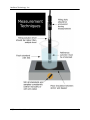
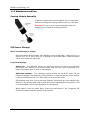
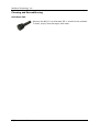
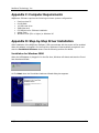
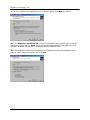
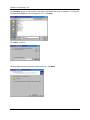
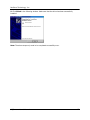
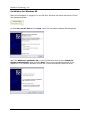
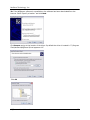
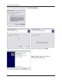
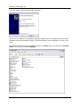
For Sales & Service Contact 2650 E. 40th Ave. • Denver, CO 80205 Phone 303-320-4764 • Fax 303-322-7242 1-800-833-7958 www.geotechenv.com NexSens Technology, Inc. TABLE OF CONTENTS 1 Sensor Operation ................................................................................................................3 1.1 1.1.1 1.1.2 1.1.3 1.1.4 2 Ion Selective Electrode Sensors ...................................................................................3 WQ-FL – Fluoride ISE Sensor ......................................................................................................... 3 Making ISE Sensor Measurements................................................................................................... 4 Maintenance and Care ..................................................................................................................... 8 ISE Sensor Troubleshooting Guide ................................................................................................ 10 Software Operation...........................................................................................................12 2.1 2.2 2.3 2.4 2.5 2.6 Working with Data ....................................................................................................12 Data Validation and Review ......................................................................................15 Changing Software Settings .......................................................................................17 Science Library..........................................................................................................19 Help and Support .......................................................................................................20 Working with Project Files ........................................................................................21 Appendix ..................................................................................................................................23 Appendix A: Material Safety Data Sheets..............................................................................23 Appendix B: Warranty and Service .......................................................................................23 Appendix C: Computer Requirements ...................................................................................24 Appendix D: Step-by-Step Driver Installation .......................................................................24 Appendix E: ISE Frequently Asked Questions.......................................................................33 What is a WQSensor? WQSensors offer the latest in smart sensor technology with direct computer interface. An integral USB connector offers a simple, hassle-free connection without meters, batteries, or power supplies - displaying the data in real-time directly onto the PC. Common water quality parameters include: temperature, dissolved oxygen, pH, ORP, NO3, NH4, and Cl. Every sensor ships with WQSensor Software, which offers a simple graphical interface to the smart sensors. The software includes the popular NexSens SCIENCE LIBRARY with an interactive periodic table, unit converter, and other useful science utilities. Download a FREE copy today! Software Installation WQSensor Software is distributed on CD-ROM. The setup program starts automatically when the CD is inserted. If the program does not load automatically, you can manually start the setup process by running Setup.exe from the CD ROM drive. We suggest that you accept the default options presented by the WQSensor Software setup program. Uninstalling WQSensors Software If you need to uninstall WQSensor Software, click Settings in the Start Menu. Select Control Panel, followed by Add / Remove Programs. Follow the step-by-step instructions to remove WQSensor Software and all associated files. WQSensors User’s Manual 2 NexSens Technology, Inc. 1 Sensor Operation 1.1 Ion Selective Electrode Sensors 1.1.1 WQ-FL – Fluoride ISE Sensor WQSensor probes come ready to go and with most of the accessories you will need. Additionally, you will need calibration buffers and calibration beakers or containers. These items should be located in any lab where WQSensors will be used, or they can be purchased from a local chemical supplier. These supplies may also be purchased from a NexSens Technology dealer: http://www.nexsens.com/company/where_to_buy.htm WQ-FL Sensor These replaceable tip sensors offer ion specific measurements. An internally stored unique ID and GLP file ensures quality data, and tracks calibration and sensor status. Fluoride Package Includes: WQ-FL: ISE sensor with 6 feet of cable and integral USB connector and FL module. 1000 ppm F- Standard F- Reference Fill Solution F- ISA (TISAB) ISE storage bottle WQSensor Standard Software & Knowledge Library CD WQSensor Quick Start Guide WQ-FL Sensor Specifications Concentration Range Temperature Range pH range Reproducibility Known Interferences Minimum Sample Size Size: WQSensors User’s Manual 0.02 ppm to saturation (1 x10⁻⁶ M to saturation) 0 to 80°C 5 to 7 @ 10-6 M 5 to 11 @ 0.1 M ±2% OH5 mL in a 50 mL beaker Electrode length 155 mm Body Diameter 12 mm Cap Diameter 16 mm Cable Length 6 ft. 3 NexSens Technology, Inc. 1.1.2 Making ISE Sensor Measurements Preparing ISE Sensors for Measurements 1. Remove the protective cap covering the sensor tip. Caution: Do not touch the sensing element with your fingers. 2. The Reference Fill Solution in the reference chamber should be above the reference fill line in the electrode. If the reference fill solution is below this line, add Reference Fill Solution from the bottle provided. To fill, slide the sleeve of the electrode Fastfill cap down to uncover the fill holes. 3. Shake the electrode downwards like a thermometer to remove any air bubbles trapped inside. Make sure to slide Fastfill sleeve to the closed position. 4. Rinse the electrode with distilled or de-ionized water, blot dry. Do not rub dry. 5. Immerse the tip of the electrode in distilled or de-ionized water and stir the water for 5 minutes. This will properly clean the electrode. WQSensors User’s Manual 4 NexSens Technology, Inc. Making ISE Sensor Measurements The quality of results depends on the quality and accuracy of the measurement technique and standards used. The following guidelines are recommended. 1. Prepare fresh standards for calibration daily. Prepare at least two standard solutions that differ in concentration by a factor of 10 and bracket the expected sample values. The standards are typically prepared by diluting a 1000 ppm stock solution of the ion to be measured. Use high quality distilled or deionized water for dilution. 2. Always add ISA to ensure that all samples and standards have a similar ionic strength. Use ISA in a 1:1 sample to ISA ratio for the WQ-FL probe.* 3. Calibrate and measure all samples and standards at the same temperature (within 1°C). If temperature changes occur, the sensor should be recalibrated. 4. Always have the Fastfill sleeve open during measurements. This puts atmospheric pressure on the reference fluid giving a more reproducible flow out of the junction. 5. After immersion in solution, check the electrode for any air bubbles on the sensing element. Remove any air bubbles by gently tapping on the electrode. 6. Make sure that the Reference Filling Solution is higher than the sample level. 7. Make sure that the sample level covers the immersion line on probe. 8. Stirring is recommended as it decreases the amount of time needed to reach equilibrium. Stir thoroughly at a slow to moderate speed, using either a magnetic stirrer or the probe as a stirring rod. Stirring rate should be consistent among all standards and samples. Note: Magnetic stirrers may generate enough heat to change solution temperature. A piece of insulating material such as cork, cardboard, or Styrofoam between the stir plate and beaker will help prevent heat transfer. 9. Always rinse electrodes with distilled or deionized water between measurements. Blot dry. Never rub dry. *Note: The WQ-FL sensor functions in a pH range of 5-7 for dilute solutions, and 5-11 for more concentrated samples. The addition of the TISAB ISA in a 1:1 ratio adjusts the ionic strength and also masks interfering compounds or ions from the probe. The TISAB ISA has an acetate buffer at pH5.4, so it also helps to adjust the pH to the appropriate range. WQSensors User’s Manual 5 NexSens Technology, Inc. WQSensors User’s Manual 6 NexSens Technology, Inc. Calibrating ISE Sensors Prepare two standard solutions that differ in concentration by a factor of ten and bracket the expected sample concentration range (i.e 10 ppm & 100 ppm standard if measuring samples between 20 and 50 ppm). Standards should be made fresh daily. The standards should be at the same temperature as the sample. During or after calibration, observe the mV reading slope. Slope is defined as the change in millivolts observed with every ten-fold change in concentration. A WQ-FL sensor slope should typically be between 58.2 mV +/- 5mV at 25 °C per decade of concentration. Every 1/2 a degree in temperature generally moves this value up or down 0.1 mV. Observing the slope value provides the best means for checking electrode performance. This can be done by checking the GLP file or by turning on mV in the Settings menu during calibration. 1. Connect the ISE sensor to the PC via the USB connector. 2. Slide the sleeve of the electrode FastFil cap down to uncover the fill holes. 3. Place 100 mL of the lower concentration standard into a 150 mL beaker. Add 2 mL of ISA. Stir thoroughly. Note: A smaller volume of standard and ISA may be used, but ensure the standard covers the immersion line indicated on the probe, and that ISA is added in a 50: 1 standard to ISA ratio. 4. Rinse electrode with distilled or de-ionized water, blot dry, and then place in the beaker. Current readings in concentration and mV will appear on the screen. Wait for the mV readings to stabilize, this could take 1-2 minutes. 5. Press the Calibrate button and click on the ISE ppm reading. Enter the concentration value of the first standard and press the Calibrate button. 6. Measure 100 mL of the higher concentration standard into a second 150 mL beaker. Add 2 mL of ISA. * Stir thoroughly. 7. Rinse electrode with distilled or de-ionized water, blot dry and place in the second beaker. Current readings in concentration and mV will appear on the screen. Wait for the readings to stabilize, this could take 1-2 minutes. 8. Press the Calibrate button and click on the ISE ppm reading. Enter the concentration value of the second standard and press the Calibrate button. ISE sensors should be calibrated as often as possible, such as each day before use. For maximum accuracy, calibrate every one to two hours. Calibration drift can be checked by immersing the probe in standard. If the value has changed significantly since calibration, recalibrate. WQSensors User’s Manual 7 NexSens Technology, Inc. 1.1.3 Maintenance and Care Sensing Module Assembly Install the replacement sensing module into the electrode body by screwing the sensing module until it is hand tight. Warning: Do not touch the sensing element with your fingers or over tighten the sensing module. ISE Sensor Storage Short Term Storage (1-3 days) Rinse the electrode thoroughly with distilled or de-ionized water. Place the tip in a solution of 2 mL of ISA in 100 mL of distilled or de-ionized water. Slide the Fastfill sleeve up to close the refill holes. Long Term Storage Sensor tip: The electrode sensor tip should be stored dry. Rinse the electrode thoroughly with distilled or de-ionized water and blot dry. When completely dry, place in protective boot in which it was shipped. Reference chamber: The reference junction should be wet at all times. Fill the reference chamber with Reference Filling Solution so that the surface of the solution is above the Reference Fill line. Slide sleeve up to close refill holes. Salt deposits may form on the reference chamber. Wipe away any salt deposits with distilled or de-ionized water. Warm water will remove salt deposits more quickly, and is recommended if there is an abundance of salt deposits. When ready to use the probe again, follow the instructions in the “Preparing ISE Sensors for Measurements” section of the manual. WQSensors User’s Manual 8 NexSens Technology, Inc. Cleaning and Reconditioning Solid State ISE: Although the WQ-FL is a solid state ISE, it should not be polished. To clean, simply rinse thoroughly with water. WQSensors User’s Manual 9 NexSens Technology, Inc. 1.1.4 ISE Sensor Troubleshooting Guide Problems may arise due to errors with: Electrode function Standards Samples Technique Follow the steps below to isolate the source of the problem. Electrode Function The following steps should be performed to test electrode slope. Slope is defined as the change in millivolts observed with every ten-fold change in concentration. A WQ-FL sensor slope should typically be between 58.2 mV +/- 5mV at 25 °C per decade of concentration. Every 1/2 a degree in temperature generally moves this value up or down 0.1 mV. Observing the slope value provides the best means for checking electrode performance. This can be done by checking the GLP file or by turning on mV in the Settings menu during calibration. The difference between the mV values of first and the second standards is identified as the electrode slope. If the electrode slope is not within the normal range, the following procedure may restore the electrode. Before beginning, check that the Reference Fill Solution level in the reference chamber is higher than the reference fill line. 1. Soak the electrode in a 10 ppm standard solution for 2 hours before use. 2. Recheck the mV slope. Note: All standard solutions should be prepared fresh. You must use ISA. All standards must be at the same temperature as the calibration reagent. If the electrode slope is still outside the normal range after this procedure, please contact the NexSens technical service department. Standards: The quality of results depends greatly upon the quality of the standards. Always prepare fresh standards when problems arise; it could save hours of troubleshooting. Error may result from contamination of prepared standards, accuracy of dilution, quality of distilled water, or a mathematical error in calculating the concentrations. Keep all solutions tightly covered when not in use. Samples: If the electrodes work properly in standards, but not in samples, there may be interfering ions, complexing agents, or substances which could affect responses. If possible, determine the composition of the samples and use the appropriate complexing agents for interfering ions. Check that the pH of the solution is within the operating range of the probe. WQSensors User’s Manual 10 NexSens Technology, Inc. Be sure that the expected concentration of the sample is within the measurement range of the probe. Technique Closely follow the methods described in the “Making ISE Sensor Measurements” section of the manual. WQSensors User’s Manual 11 NexSens Technology, Inc. 2 Software Operation 2.1 Working with Data After running WQSensors software and connecting a WQSensor, real time data can be viewed in the Sensors menu. When a single sensor is connected it will be displayed as shown. The serial number of the sensor, as well as the time of last obtained reading, is displayed on the bottom of the screen. If multiple sensors are connected, they will be displayed in a tabular format as shown. Numerical buttons on the bottom of the screen allow scrolling through each panel of four sensors. WQSensors User’s Manual 12 NexSens Technology, Inc. Logging Data Data can be logged either as single measurements or as a stream of measurements over userspecified time intervals. This interval can be specified by clicking the Interval button in the Settings menu. Logged data can be viewed by clicking the Report button in the View menu. To log a single data point, click on the left hand side of the Log button. The left side of the button will turn blue and a short animation with the letter L will display on the bottom left hand corner of the screen. To start logging continuous measurements at the user defined interval, click on the right hand side of the Log button. The entire button will turn blue and at the log interval, a short animation with the letter L will display on the bottom left hand corner of the screen. WQSensors User’s Manual 13 NexSens Technology, Inc. Calibrating Sensor Readings To calibrate Sensor Readings: 1. Click on the Calibrate button 2. Select the parameter reading to calibrate as shown below 3. Enter the calibrated value 4. Click the Calibrate button again to complete the change A short animation with the letter C will display on the bottom left hand corner of the screen. Temperature and mV values cannot be calibrated (except for calibration of ORP). This calibration is stored on the sensor, which means that the sensor can be calibrated on one computer and still returned calibrated results no matter which other computers it is used on. Refer to the calibration guidelines in the sensor sections earlier in this manual for information on when and what values to calibrate with. WQSensors User’s Manual 14 NexSens Technology, Inc. 2.2 Data Validation and Review Good Laboratory Practice Files WQSensors software automatically records every calibration to a Good Laboratory Practice (GLP) file. The GLP file will include the time, data, sample readings, and diagnostic data for each calibration. This file is stored on the sensor and will carry over from PC to PC. WQSensors User’s Manual 15 NexSens Technology, Inc. Data Reports Data is stored inside WQSensors software project files and can be viewed in graphical, statistical, and tabular formats. To view this data click the View button, then click the Report button. Select the desired report options and then click Generate. From the report tool bar data can be saved, printed, or exported to Microsoft Excel ©. WQSensors User’s Manual 16 NexSens Technology, Inc. 2.3 Changing Software Settings Customizable options are available in WQSensors software in the Application Settings menu. Show introduction animation? This option specifies whether to display the opening animation that plays each time WQSensors software is started. Un-checking this box will disable the software from playing the animation each time. Remember last menu location? This option specifies whether the WQSensors software should reload the last menu opened each time the WQSensors software starts. Un-checking this box will make the Sensors menu the default page when starting WQSensors software. This feature is useful if a specific Library menu table or formula is used often. Convert Celsius to Fahrenheit? This option specifies whether to display temperature values in Celsius or Fahrenheit. Un-checking this box will display all temperature readings in degrees Fahrenheit. Show mV values? This option specifies whether the Sensors menu should display the mV readings from the sensors. Un-checking this box will disable the display of mV values. mV readings are diagnostic information and are not required to take measurements. They are useful, however, in determining sensor performance and calibration. WQSensors User’s Manual 17 NexSens Technology, Inc. Changing Log Interval The intervals at which the sensor logs data can be changed in the Software Logging Interval menu. Clicking the Interval button on the Settings menu displays the current log interval in seconds. To change the interval, enter a new value and click Apply. Please see the Logging Data section for starting and stopping this feature. WQSensors User’s Manual 18 NexSens Technology, Inc. 2.4 Science Library The WQSensor software Library menu is a desktop reference for water, wastewater, and environmental professionals. It's packed with tables, calculations, and many conversions. Features include: Converting units of measure Calculating flow over a weir Determining the inside diameter of PVC pipe Finding the ammonia tolerance level for rainbow trout Determining the atomic weight of bromine Finding the concentrations of elements in sea water And much more... WQSensors User’s Manual 19 NexSens Technology, Inc. 2.5 Help and Support WQSensors software integrates the internet into part of its functionality. Software updates, technical support, and other information can be obtained in the Help menu. Technical questions or comments NexSens technical staff can be reached right inside of the program. Click on the Help button in the Help menu to send an email directly to NexSens technical support. Be sure to include a name and email address that they can contact you with. If you would prefer to be contacted by phone, include that in the message along with your phone number. Note: An internet connection is not required to run WQSensors software. WQSensors User’s Manual 20 NexSens Technology, Inc. 2.6 Working with Project Files When WQSensors software first runs, it defaults to Project_1. This is simply a default name for the default project file. Each project file contains information about every sensor that was connected to the computer while that file was open, as well as any data that was collected during that time as well. Creating new project files To create a new project, for a specific experiment or study, click the New button in the File menu and enter a project name. Click OK when finished. WQSensors User’s Manual 21 NexSens Technology, Inc. Open an existing project To open a previously created project, select Open from the File menu. Select the project to open and click OK. WQSensors software will begin using that project file as the current project. Renaming project files To rename the current project, select Rename from the File menu. Enter a new name and click OK. To rename projects, other than the current one, simply select Open and select the project to be renamed from the list of existing projects. This project can then be renamed on this tab. WQSensors User’s Manual 22 NexSens Technology, Inc. Appendix Appendix A: Material Safety Data Sheets Material Safety Data Sheets can be found at: http://www.nexsens.com/support/msds.htm Appendix B: Warranty and Service NexSens Technology, Inc. warrants WQSensors against defects in materials or workmanship for a period of 6 months from the date of delivery to the original customer. This warranty is limited to the replacement or repair of such defects, without charge, when the instrument is returned to NexSens Technology, Inc. Damage due to accidents, misuse, tampering, lack of reasonable care, loss of parts, failure to perform prescribed maintenance, or accidents of nature are not covered. This warranty excludes all other warranties, express or implied, and is limited to a value not exceeding the purchase price of the instrument. Limitation of Warranty This warranty is not applicable to any NexSens Technology, Inc. product damage or failure caused by (i) failure to install, operate or use the product in accordance with NexSens Technology, Inc. written instructions, (ii) abuse or misuse of the product, (iii) failure to maintain the product in accordance with NexSens Technology, Inc. written instructions, (iv) any improper repairs to the product, (v) use by you of defective or improper components or parts in servicing or repairing the product, or (vi) modification of the product in any way not expressly authorized by NexSens Technology, Inc. Warning: NexSens Technology, Inc. products are not authorized for use as critical components in any life support system where failure of the product is likely to affect its safety or effectiveness. Authorized U.S. Service Centers – Corporate Headquarters – NexSens Technology, Inc. 1328 Parkway Court Dayton, Ohio 45432 – Phone: (937) 426-2703 – Fax: (937) 426-1125 – E-Mail: [email protected] WQSensors User’s Manual 23 NexSens Technology, Inc. Appendix C: Computer Requirements WQSensor Software requires the following minimum system configuration: Pentium class PC 64 MB RAM 100 MB hard drive 2MB video card CD-ROM drive for Software installation Adobe Flash Windows 2000 (SP1 or higher) or Windows XP Appendix D: Step-by-Step Driver Installation After installation of the WQSensor Software, USB communicate with the sensor will be enabled. When the adapter is plugged in for the first time, Windows will automatically recognize it and start the Found New Hardware wizard. See the following sections for details. Installation for Windows 2000 When the USB adapter is plugged in for the first time, Windows will detect and start the Found New Hardware Wizard: 1. Click Next when the Found New Hardware Wizard dialog box appears. WQSensors User’s Manual 24 NexSens Technology, Inc. 2. Check the “Search for suitable driver for my device” option. Click Next to continue. 3a. If the WQSensor installation CD is in the CD-ROM drive, place a check mark in the “CDRom drives” option and click Next. This is the recommended method, if the WQSensor CD is available. Windows will scan the CD and automatically install the driver. 3b. If the WQSensor software is unavailable or the software has been downloaded from the internet. Check “Specify a location” and click Next. WQSensors User’s Manual 25 NexSens Technology, Inc. Click Browse and go to the location of the driver. By default the driver is located in “C:\Program Files\NexSens\WQSensor\Driver\wqsensor.inf”. Click Open. Click OK to continue. 4. Once Windows has successfully found the driver, click Next. WQSensors User’s Manual 26 NexSens Technology, Inc. 5. Click Finish in the following window. Make sure that the driver has been successfully installed. Note: The above steps only need to be completed successfully once. WQSensors User’s Manual 27 NexSens Technology, Inc. Installation for Windows XP When the USB adapter is plugged in for the first time, Windows will detect and start the Found New Hardware Wizard: 1. Select No, not this time and click Next, when the Found New Hardware Wizard appears. 2a. If the WQSensor installation CD is in the CD-ROM drive then click the Install the Software automatically option and click Next. This is the recommended method, if the WQSensor CD is available. Windows will scan the CD and automatically install the driver. WQSensors User’s Manual 28 NexSens Technology, Inc. 2b. If the WQSensor software is unavailable or the software has been downloaded from the internet. Check “Specify a location” and click Next. Click Browse and go to the location of the driver. By default the driver is located in “C:\Program Files\NexSens\WQSensor\Driver\wqsensor.inf”. Click Ok WQSensors User’s Manual 29 NexSens Technology, Inc. 3. If the following dialog box appears, click Continue Anyway. 4. Windows will search for the driver. Make sure that the driver has been successfully installed. If it has been, click Finish. Note: The above steps only need to be completed successfully once. WQSensors User’s Manual 30 NexSens Technology, Inc. If for any reason the following window appears: The driver will need to be reinstalled. Typically Windows will not redisplay the Found New Hardware wizard automatically again. Therefore Windows Device Manager will have to be used. The Device Manager can be accessed by going to the Start menu and clicking on Control Panel. Click on the file labeled System. WQSensors User’s Manual 31 NexSens Technology, Inc. The System Properties dialog box will appear. Go to the Hardware tab and click Device Manager. You should see a device labeled USB Device that has a yellow icon by its name. WQSensors User’s Manual 32 NexSens Technology, Inc. Right click on the device and select Update Driver. This will restart the Found New Hardware Wizard. Go back to step one and follow to install the driver. If you need further assistance call a NexSens Support Representative at (937)-426-2151 or email us at [email protected]. Installation for Windows Vista In Windows Vista, driver installation is automatic. You may see a small screen pop up on the bottom right hand corner of the screen for the first few seconds the device is plugged in, after which it will appear in the software. Appendix E: ISE Frequently Asked Questions 1. 2. 3. 4. What is an ISE probe? What is ISA, and why is it added when using many of the ISE probes? What is the relationship between ionic activity and concentration? What is the difference between Nitrogen-Nitrate and Nitrate? Or NitrogenAmmonium and Ammonium? 5. How do you convert from Molarity (M) to parts per million (ppm) and mg/L? 6. How do I dilute the stock standard to make lower concentrations of standards for calibration? 7. What is the real world range of ISE probes? 1. What is an ISE probe? ISE stands for Ion Selective Electrode. Ion Selective Electrodes are membrane-based electrochemical sensors. The membrane on the electrode is the component that makes the electrode selective for a particular ion. Four different types of ISEs can be described based on the material of the membrane: Glass membrane (pH) Solid State membrane (Chloride, Bromide, Fluoride) WQSensors User’s Manual 33 NexSens Technology, Inc. Polymeric membrane (Ammonium, Calcium, Nitrate) Gas Permeable membrane (Dissolved Oxygen) When an ISE probe is placed in solution, the ion of interest (i.e. chloride, calcium, etc.) will interact with the ISE membrane in a selective way. An electrical potential will develop across the membrane. This electrical potential is proportional to the free ionic activity of the solution. When the activity increases (more free ions in solution) the electrode potential becomes more positive when the electrode is sensing a cation and more negative when the electrode is sensing an anion. This electrical potential is then measured against a stable electrical potential in a reference electrode. WQSensors use combined reference electrodes, meaning that the reference electrode is contained within the same probe body as the electrochemical sensing electrode. For a tenfold change in ionic activity (i.e. 10ppm to 100ppm), the electrode potential at 25°C changes by 59.2 ± 5 mV when the ion being measured is monovalent (Br-, Cl-, F-, NO3-, NH4+), and 29.6 ± 5 mV when the ion being measured is divalent (Ca+2). 2. What is ISA, and why is it added when using many of the ISE probes? ISA stands for ionic strength adjuster. It is important to add ISA to all standards and samples when using most ISE electrodes (with the exception of a few, such as pH and dissolved oxygen). The addition of ISA ensures that all samples and standards will have a similar ionic strength. This is important because the ionic strength of a solution affects the relationship between activity and concentration. By bringing the ionic strength of all samples and standards to a similar level, the effect of variable ionic strengths on the activity is overcome thus reducing the margin of error. WQ Sensor User’s Manual 34 NexSens Technology, Inc. 3. What is the relationship between ionic activity and concentration? Ion selective electrodes respond to ionic activity in a solution. However, most researchers are really interested in the total concentration of a species in solution. Although ionic activity is related to concentration, they are not necessarily the same. Two factors affect the relationship between activity and concentration: the presence of complexing species; and the total ionic strength of a solution. First, activity refers only to free, unbound ions. A portion of the total concentration may be bound or complexed by other ions in the solution and therefore does not exist in the free ionized state. An ISE probe only senses the activity of the free unbound ions. Second, ionic activity depends on the total ionic strength of the solution, which is a measure of its overall ionic composition. In general, as ionic strength increases, the ratio of ionic activity to the ionic concentration (that portion of the total concentration which is uncomplexed) for a given species changes. This ratio is called the activity coefficient. For solutions which contain only uncomplexed ions, the total concentration is simply the ionic activity divided by the activity coefficient. Adding ISA (ionic strength adjuster) to all standards and solutions helps to remove any differences among solution caused by variations in ionic strength. 4. What is the difference between Nitrogen-Nitrate and Nitrate? Or NitrogenAmmonium and Ammonium? Nitrogen exists in various forms, including nitrate (NO3-), ammonium (NH4+), and ammonia (NH3). In order to differentiate among the various forms of nitrogen in a sample, analysis of nitrogen is often expressed in terms of the amount of nitrogen combined in its various forms, such as nitrate-nitrogen, or ammonium-nitrogen. The term nitrate-nitrogen defines all the nitrogen in the sample that exists as nitrate and the term ammonium-nitrogen defines all the nitrogen in the sample that exists as ammonium. There is a simple mathematical relationship to convert from the expression of nitrate to nitrate-nitrogen, or ammonium to ammonium-nitrogen. This relationship is based on the chemical formula for the ion. Every element has an atomic mass. The atomic mass for nitrogen is 14, because it has 7 electrons and 7 protons. The atomic mass for oxygen is 16, because is has 8 protons and 8 electrons. The chemical formula for nitrate is NO3-. It is a combination of 1 nitrogen atom, which has an atomic mass of 14, and 3 oxygen atoms, each of which has an atomic mass of 16. Therefore, the atomic mass for nitrate is 62 (14+ 48 = 62). If a solution had a concentration of 62 ppm nitrate, it would contain 14 ppm nitrogen and 48 ppm oxygen. This can be expressed either as 62 ppm nitrate, or 14 ppm nitrate-nitrogen. To convert from nitrate-nitrogen (NO3--N) to nitrate (NO3-), simply multiply by 4.43: Nitrate (NO3-) = Nitrate-Nitrogen (NO3--N) x 4.43 WQ Sensor User’s Manual 35 NexSens Technology, Inc. The conversion factor 4.43 comes from the atomic mass of nitrate divided by the atomic mass of nitrogen (62/14). For instance, if 10 and 100 ppm NO3--N standards were prepared for calibration, this would be equal to 44.3 and 443 ppm NO3- standards. For ammonium-nitrate (NH4+-N) Similarly, the atomic mass for ammonium is 18. This is because ammonium is a combination of 1 nitrogen atom, which has an atomic mass of 14, and 4 hydrogen atoms, each of which has an atomic mass of 1. To convert from ammonium-nitrogen (NH4+-N) to ammonium (NH4+), simply multiply by 1.286. Ammonium (NH4+) = Ammonium-Nitrogen (NH4+-N) x 1.286 Similarly, if 10 and 100 ppm NH4+-N standards were prepared for calibration, this would be equal to 12.86 and 128.6 ppm NH4+ standards. Note: The standards sold with the WQSensors are sold as 1000 ppm NO3—N and 1000 ppm NH4+-N. 5. How do you convert from Molarity (M) to parts per million (ppm) and mg/L? The molarity of a solution is the number of moles of solute per liter of solution. The molar mass of any particle (atom, molecule, formula, or ion) is the sum of the average atomic masses of all atoms forming that particle. This is also known as molecular weight. The molar mass of an atom is its average atomic mass expressed in grams. The atomic mass of all atoms can be found in the periodic table. For dilute solutions, one part per million equals one mg/L. In most cases, the two are considered equal. To convert from molarity to ppm, first determine the molar mass of a substance. For instance, chloride has a molar mass of 35.5 (rounded up from 35.45). A solution with 1 M concentration would have 35.5 g of chloride per 1 L of solution. Chloride Molarity moles/Liter (M) 1M 10-1 M (0.1 M) 10-2 M (0.2 M) 10-3 M (0.3 M) 10-4 M (0.4 M) grams/L (g/L) Parts Per Million (ppm) milligrams/L (mg/L) 35.5 3.55 0.355 0.0355 0.00355 35,500 3,550 355.0 35.5 3.550 35,500 3,550 355.0 35.5 3.550 WQ Sensor User’s Manual 36 NexSens Technology, Inc. 6. How do I dilute the stock standard to make lower concentrations of standards for calibration? Standards are made from the 1000 ppm or 10-1 M stock standard. When preparing standards, you should prepare two standards that differ by a factor of 10, and bracket the expected concentration range of your sample. For example, if you expect the chloride concentrations in your samples to be 20 to 80 ppm, you should prepare standards that are 10 and 100 ppm. To prepare standards from your stock standard, follow the subsequent formula: V1C1 = V2C2 Where V=Volume and C=Concentration. V1C1 are the volume and concentration of your stock standard, where V2C2 are the volume and concentration of your diluted standard. When preparing a new standard from stock standard, V1 (volume of stock standard) is your unknown. For example, say you want to prepare 100 mL of 10 ppm and 100 ppm chloride standard from your 1000 ppm stock standard. Then, you need to figure out what volume of your stock standard is used: For the 10 ppm standard: V1 = the volume of stock standard used to make your new more dilute standard. This is your unknown. C1 = 1000 ppm in the stock solution V2 = total volume made in the more dilute standard you are making = 100 mL C2 = concentration of new more dilute standard = 10 ppm V1 = (V2C2)/C1 V1= (100*10)/1000 = 1 mL of 1000 ppm stock standard Therefore, pipette 1 mL of 1000 ppm standard into a 100 mL volumetric flask, then bringing to 100 mL volume with distilled or deionized water. Note: ISA is added to the standard after the dilution. Its volume is not considered in the dilution. This is because it will also be added to the samples. This way, both the standards and samples are equally diluted by the ISA. For the 100 ppm standard: V1 = the volume of stock standard to use to make your new more dilute standard. This is your unknown. C1 = 1000 ppm in the stock solution V2 = total volume made in the more dilute standard you are making = 100 mL C2 = concentration of new more dilute standard = 100 ppm V1 = (V2C2)/C1 V1= (100*100)/1000 = 10 mL of 1000 ppm stock standard WQ Sensor User’s Manual 37 NexSens Technology, Inc. Therefore pipette 10 mL of 1000 ppm standard into a 100 mL volumetric flask, then bringing to 100 mL volume with distilled or deionized water. Note: ISA is added to the standard after the dilution. Its volume is not considered in the dilution. This is because it will also be added to the samples. This way, both the standards and samples are equally diluted by the ISA. 7. After soaking a Nitrate electrode overnight in a low standard, why does it not respond when I try to calibrate? This is a common problem with all nitrate electrodes. Soaking overnight in a standard ‘numbs’ the membrane to any changes and needs to be air dried for at least 12 to 24 hours before you try to use it again. Next time you want to soak the electrode prior to use, try only soaking it for 10-20 minutes and then calibrating. 8. What is the real world range of ISE probes? The specified range of ISE probes given in the “Specifications” section of this manual is for clean solutions without any interference ions present. For example, chloride ISE probes are given as 1.8ppm to 35,500ppm In real world samples the range, as you measure near the limits, may be quite less depending on the identity of interference ions, temperature of samples vs. temperature of calibration standards, or fouling of the sample being measured. To ensure measurement results match the probe range: 1. Measure samples in clean beakers and environments where the temperature of the sample matches the temperature of the standard the probe was calibrated. 2. Run multiple samples per measurement. 3. Ensure long term care of the probe by using ISA buffer solution in measurement standards as well as keeping the probe filling solution clean and full inside of the probe body. WQ Sensor User’s Manual 38 NexSens Technology, Inc. WQ Sensor User’s Manual 39