1
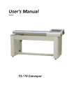
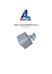
INNOVA SERIES MULTI-PURPOSE AUTOMATIC CUTTING MACHINE USER MANUAL 1. GENERAL INFORMATION correct machine functioning. 1.1 Introduction Failure to observe the safety warnings may lead to injury, ) both for the operator and other persons. Dear Customers, congratulations on your purchase of the INNOVA SERIES sawing machine. It is designed as a The danger signal indicates situations of special danger heavy-duty rail saw with compact size, which can handle all where the operator risks serious injuries. fabrication needs. So it is ideal for cutting and profiling every 1.2.4 Refer to illustrations kind of slab or tile. When the text refers to an illustration, for example: “... (Fig.12.1C) ...”, refer to part C in figure number 12.1. Some Characteristics: illustrations are included in the context, while others are annexed. Multi-purpose Cutting 1.3 Recommendations for assistance Beveling Grinding Notching When compiling this manual, we kept in due consideration all Polishing the adjustment and service operations which are part of Drilling normal maintenance. We recommend that no repairs or Different cutting length operations are carried out which are not indicated in this 2000mm manual. All operations which require parts to be dismantled 2500mm 3000mm Cutting head can tilt and rotate to any angle within 360 must only be carried out by qualified personnel. degree. Thus you can cut and polish the slope at any 1.4 Introduction to use angle. This USE AND MAINTENANCE manual must be read before Before beginning machining with the sawing machine, read using and kept by the foreman within building site, so it is this instructions manual carefully to understand the machine, always available for consultation. The manual is to be its uses and any possible counter-indications. The machine considered part of the machine and must be kept for future must be used exclusively for the uses hereby specified, use it reference for the whole machine life. If it is damaged or as recommended in this manual and do not try to tamper with mislaid, a new copy can be requested from the manufacturer. it or force it, or to use it for purposes not mentioned. We To guarantee the safety of the operator, the safety of machine declines all responsibility in the case of non observance of the functioning and a long life for the machine, the instructions in laws which regulate the use of such equipment, in particular: the manual must be respected, together with the safety and improper use, power supply anomalies, neglect of work accident prevention regulations as per current maintenance, unauthorized modifications, partial or total non legislation. Suitably safe equipment must be used (safety observance of the instructions contained in this manual. shoes, gloves and glasses). 1.2 Consulting this manual -It is forbidden to carry out modifications of any kind on the machine’s metal structure, and electrical system. The following description is various types of symbol which 1.5 Description will be seen when reading this manual. Innova 2000/2500/3000 series are sawing machines ) designed and manufactured by us for cutting tiles, ceramics, The notes highlight information which is particularly useful for marble, granite, cement products and similar products. Only continuous crown or sector diamond-dressed blades, power supply unit or electrical motor. constantly water-cooled can be used. Blades for dry cutting 5. Remove rings, watches, bracelets and ties: experience has must not be used under any circumstances and any material shown that these and other objects can lead to accidents. In not specified in this manual must not be cut with the machine. addition, make sure sleeves are closed tightly on the wrists, We decline all responsibility for damage caused by improper keep hair tied back and use robust footwear. use of the equipment. 6. Do not machine pieces which are beyond the size suitable for the characteristics recommended by the machine manufacturer 1.6 Technical Characteristics 7. Tighten screws, bolts and ring nuts for each instrument to the torque envisaged, without exceeding the normal values and INNOVA is a very versatile machine which can be used for a without using levers or hitting the spanners. vast range of uses. 8. Always use the personal protections: accident prevention glasses which conform with standards, suitably sized and Technical Data customized gloves, ear muffs or earplugs and hair nets, if Diameter of diamond blade mm 350 necessary. Diamond blade center hole mm 25.4 9. Use the original tools recommended by the manufacturer to Cutting dimension (LxW) mm 2000/2500/3000x1750 Packing Size mm 10. Always keep the hands far from the machining areas when Net Weight Kg the machine is running. Before removing any parts near the disk, Gross Weight Kg stop the disk rotating by pressing the stop push-button. Rotation direction of blade Anticlockwise Frequency Hz 50 Motor Power Kw 3.8 Motor Speed rpm 2800 Voltage V 380 ensure maximum machine performance. 11. The instructions contained in this manual are for the users of the machine (operators, maintenance personnel). 12. Never use cracked or deformed grinding disks. 13. Never use the disks at a speed higher than that indicated by the manufacturer. 14. Only use diamond-dressed crown disks, of a type suitable for the material to be cut and which conforms to the safety 1.8 General Warnings 1.7 General Safety Precautions Do not load the machine with excessively heavy pieces. Pay attention to the stability of both the pieces, before, during and after cutting, and the machine, using, for Please remember that this machine has been manufactured example, the additional support surface set up at the to offer, as well as better performance, maximum safety: same height as the work surface (series of rollers with however, it is the operator who must guarantee this safety, by taking the necessary precautions in all work phases. The operator is advised to: idle rollers). Dispose of waste liquids from the cutting process in suitable containers. 1. Ensure that the earthing unit is suitable. 2. Only work with all the guards in place and working correctly. 3. Keep the machine clean: the general cleaning of the machine (and work surfaces in particular) is an important safety factor. 4. Stop the machine completely before cleaning it or removing any guard (for maintenance or removal of any component): turn 1.9 Safety Measures The INNOVA sawing machine was designed to be used in building sites in daylight and in laboratories with natural or artificial light not less than at least 500 LUX. the main switch to zero and disconnect the plug. If the machine is cleaned with water jets, do not spray water directly on the The machine must not be used in environments where there is the risk of explosions and/or fires or in in Innova. underground sites. 1.11.1 Guards and Safety Devices - The INNOVA sawing machine can only function if it is fitted with all the protection devices in perfect condition. The machine is fitted with fixed guards secured with fixing - Do not use improvised and/or faulty power lines. crews to prevent access to the moving and dangerous parts. - The power supply lines in the building site must be placed All the fixed guards, and covers secured with screws have in such a way that they cannot be damaged. Do not place the been designed to protect the operators (maintenance sawing machine on top of the power supply lines. personnel, technicians etc.) from injuries caused by electrical - The power supply lines must be placed in such a way that discharges and moving mechanical parts. Therefore, please they prevent water from penetrating the connectors. Only don’t modify or remove the guards from the positions where use connectors fitted with a water jet protection (IP55). they have been designed for. - Electrical unit repairs must only be carried out by or Before carrying out any machine maintenance or maintenance operations when the machine is powered up or repair, the main switch must be turned off and disconnected. specialized personnel. Do not make adjustment moving. 2. MACHINE INSTALLATION The machine must be connected to the conductor with a minimum cross section of 16 mm², the connection 2.1 Lifting and Unloading point is identified with a screw welded to the frame and Please life or carry the machine with forklift or crane and by the plate with the earth symbol. make sure that the machine is securely positioned. Always check that the resistance of the cable and the capacity of the crane/forklift truck are of sufficient To stop the sawing machine, only use the appropriate switch. - size for the purpose, checking the weight of the machine on the appropriate metal plate on the machine. The symbol on the label indicates that it is forbidden to start up the machine if the guards are not all present and 2.2 Positioning functioning correctly. Put the machine in the most suitable position, bearing in mind the electrical connections. The space required for use and maintenance should be enough. 1.10 Electrical Safety Always disconnect power supply plug before moving This machine is fitted with: - the machine. a system preventing automatic start up after power supply failure During installation, ensure that the legs are perfectly level - protection against short-circuiting - motor with overload protection on the floor of the building site to guarantee the stability. 2.3 Connect the machine to main power supply 1.11 Safety Devices Check that the main power supply unit to which the machine The Innova series were designed in line with serious safety is connected has an earth connection as envisaged by standards, which given utmost safety importance to current standards, and that the socket is operating correctly. operators. Safety and accessibility are combined perfectly Remember that there must be an overload protection transfer motors stop. When the voltage returns, the motor upstream of the main power supply unit which can guarantee does not start again until the reset push-button is pressed. the safety of all conductors from short circuiting and overload The electrical cabinet is positioned on right hand side of the Ensure that the electric line has a differential machine to guarantee that the operator has easy access to overload switch upstream. the controls. The electric power supply line must be sufficient to prevent voltage drops. In particular, cable drums (with collector rings) 2.4 Machine noise level must not be used. The dimensions of the conductor must be based on the starting current and the length of the line. As The values given for the noise are emission levels and not per regulations, a 4x4 mm² conductor is sufficient, up to 50m. necessarily safe work levels. While there is a correlation After installation it is still necessary to measure the voltage, between the emission levels and the exposure levels, this with the load, both for start up and functioning. During cannot be used as a reliable indicator to establish if further functioning, voltage drop must be limited to 5%. If using precautions are required or not. The factors which influence longer conductors which are not optimal, use cable with a the real level of exposure for the worker include the duration section of at least 6mm². The power supply cable used in the of the exposure, the environmental characteristics and other building site must be fire resistant and have a suitable outer noise sources, for example, the number of machines and sheath, resistant to squashing, wear and atmospheric adjacent work areas. The exposure levels permitted can also agents. -The machine must be connected to the earthing unit in the building site. The connection point is the screw marked with a plate and an earth symbol vary from country to country. However, the following information enables the user to make a better estimation of the dangers and risks. -Prolonged exposure to noise above 85 dB(A) may The section of the earth cable should be the same as the damage health. It is therefore recommended that section of the line conductors or at least conform to current appropriate protection measures (e.g. ear muffs, plugs legislation and technical standards in the country in which etc.) are taken. the machine is used Before making the connection, check the main voltage and 3. MACHINE USE frequency correspond to the machine specifications. The power supply lines in the work area must be positioned 3.1 General Description to ensure that they are not damaged and that water will not penetrate. Only use collectors and attachments fitted with Once the machine installation has been completed, water jet protections. Do not place the machine on the power machining can begin. Innova series consists of a stainless supply lines. Suitable protection must be adopted. steel cutting surface. The 3.7 kW motor and the working Don’t use temporary machine connection. The operation head are fitted on a pre-stressed aluminum body with high must be carried out by specialized personnel. Ensure that mechanical resistance. The working head can be tilted and the attachment for the power supply cable in the plug-switch turned to any degree from 0 to 180°. The operating unit is unit housing is stable. driven by a transfer unit connected to the cutting unit. The The work area must respect accident prevention and security device standards. machine is fitted with a mobile tank. The cooling pump immersed in the tank guarantees lubrication of the disk during the cutting operation. For vertical cutting, the pieces 2.3.1 Main requirements for the electrical cabinets must have a maximum length of 3000 mm and a maximum thickness of 100 mm. For 45 degree tilted cutting, the pieces The functioning principle of the electrical cabinets envisages must have a maximum length of 3000 mm and a maximum a differential switch for starting the cutting unit and a switch thickness of 45 mm. The machine consists of a mobile for the transfer unit. If there is voltage drop, the rotation and cutting part, a fixed machine support frame, a disk cooling tank and an adjustment unit. The machine is fitted with protection devices to guarantee maximum functioning safety. Innova functions as follows: 1. Straight Cutting There is an emergency stop switch on the electric cabinet. 3.2 Functioning 3.2.1. Preparation Work 1. The power supply parameter is listed below: 3 phase 5 lines: 3 live lines 1 earth line 1 zero line 380V 50HZ Input power: 3.7kw Please fix the water-proof plug on the right leg (as shown on the picture). Please connect the 5 lines on the plug. 1. Please turn the main motor to position as shown on the picture, and then confirm label “0-0” is on one line. Use a spanner to fasten tightly the locking nut A and B. Also confirm that 0-90°is on one line, and then fasten the locking handle. It’s prohibited to operate the machine before 2. on middle position between the gap of table. Lock nut C connecting earth line to the plug. and D. 2. Fix all the screws and nuts tightly. 3. Ensure that the blade is suitable for the material being cut. 3. 300 and 350mm. with the indication on the blade cover. 4. 5. Sharpen the blade. Prepare a firebrick before cutting and start the motor to cut the brick more than 20 times 7. Start up the pump by turning on main motor and wait until until the diamond part on blade is very sharp. the water wets the blade. 8. Check the position of blade compared to the cutting line. Move the stop ring on 2 rails to change the cutting length. Ensure that the cooling liquid tank is full 6. Check if the limit switch is valid. Start up and down operation, to stop blade 10mm under the table surface. Blade size can be optional between 4. Check if the rotation direction of motor is in accordance 5. Check motor and water pump works normally or not. Turn the wheel on motor to make sure that the blade is 6. Auto cutting operation: 9. The cutting speed must be adjusted in relation to height Push the “Auto Cutting” button, then motor will work and and type of material to be cut to avoid overloading the blade go down. The cutting operation starts. When the motor. The cutting speed can be adjusted by checking, limit switch touches the stop ring, the motor will stop, during work phase, the motor absorption, which can be ascend, and move back to the starting point fast and referred to the amperometer. The speed can be adjusted then stop there. Please take away the well-cut stone and by turning the knob on main control panel. change another one, another auto cutting operation will start like above. 3.2.2. Cutting Operation 7. Manual cutting operation: Press “LEFT” “RIGHT” “UP” ”DOWN” button on the 1. Change the blade cover to smaller one. Fix milling wheel control panel, you can start manual cutting operation according to different size of stone. When the limit instead of blade. 2. Loose nut A and B, turn motor 180°and make 0-0 on one switch touches stop ring, the motor will stop. Then you need to push the relevant button to start other line. Lock the nut. 3. Put stone on the back holder (as shown on pic.) Adjust the operations. height of holder and motor to make milling wheel touches 2. Bevel Cutting the surface of stone. 4. Check if side surface of stone and the wheel is parallel. If not, adjust bit by bit one side of the back holder to make them parallel. 5. Put the wood stopper tightly between stone and steel bar. 6. Adjust the stop right on rails to proper position according to different cutting length. 7. Press “AUTO GRINDING” button to start main motor. The motor starts to mill to and fro. When every stroke stops and the motor move back to start milling again, press DOWN button manually bit by bit until the shape is finished. 8. After milling, you can change same shape grinding wheel to polish the surface of edge. Turn the revolving body on rails to make 0-45°on 4. Notching one line, then fasten the locking handle. Adjust the position of blade by pressing UP or DOWN button or turning the wheel on motor to locate blade between middle of the table gap, and stop it 10mm under the table surface. Lock nut C and D, then start cutting. 3. Grinding and milling 1. Adjust motor to the position shown on picture. 2. Put the stone on back holder like the picture. 3. Change notching blade with smaller size and sharpen it with firebrick many times. 4. Manually adjust the LEFT and RIGHT button to fix blade on middle of stone edge. 5. Start main motor and press DOWN button. As soon as the cutting depth is enough, stop pressing it right away, and press UP button to remove blade from stone. 6. 7. Drilling Slab Move blade to the second position and then start notching again. 5. Grinding Adjust cutting head to position shown on picture, you can easily drill holes on slab. 1. Move the head to position as shown on picture. 8. Polish any tilting angle 3. Adjust one side of back holder, to make sure that the surface of stone and grinding wheel parallel. 4. Adjust the 2 stop rings on rail according to different cutting length, and then push AUTO Grinding button to start grinding. Manually turn the wheel on motor to adjust pressure on stone. Change different grinding wheel until satisfied. 6. Drilling big stone The head can be fixed at any angle by turning the head to the position needed. 3.3 Operating Unit The operating unit consists of the following: Adjust cutting head to position shown on picture. 1. A sliding unit guided by bearings 2. A reducer motor 3. A cutting motor which drives the blade and wheel materials of which the machine is made. 3.4 Machine Use Check that the plug and plug-switch unit contacts are damaged or not. If they are oxidized, clean and change them immediately. For correct machine use, we recommend that the user follows these important procedures: 1. 2. Leave a minimum of 60cm of free space around the 4.2.1 Dismantling the tank machine for safety reasons. There are locking nuts on side of top. Just loose them you Do not allow unauthorized persons to approach the can easily take off it from the machine. machine during cutting. 3. Do not use the machine in areas where there is a risk of 4.2.2 Cleaning the tank after machining fire as sparks may cause fires or explosions. At the end of a work shift, dismantle the tank after emptying it Always turn off the power supply before positioning and and wash it thoroughly to remove the cutting deposits which moving the machine. have formed. Clean the tank every time that sediment forms Always ensure that the disk is not in contact with on the bottom, or at least once a day. Failure to clean the tank anything before starting up the motor. could create problems for the water pump which circulates 6. Check that the guards are all in the correct position. water for cooling the blade. To clean the tank, remove it from 7. Check that the rotation direction of the disk is the same the machine and wash it down with direct water jets. Then as that indicated on the guard. clean it by hand with cloths or brushes. 4. 5. 8. Before starting to machine, fill the water tank. Check and, if necessary, top up the level of water during use: the 4.2.3 Cleaning of the rail and table pump suction head must always be immersed. -It is absolutely forbidden to create unnecessary safety risks, by removing the machine guards. 9. The table surface and rail must be kept clean. Deposits of dirt on these surfaces may cause inaccurate cutting. All the disk adjustments must be made with the motor turned off. 4.2.4 Cleaning and maintenance of the cooling unit If water does not arrive, stop the cutting immediately to 4. MAINTENANCE prevent damaging the disk. Perform the following ordinary maintenance operations: 4.1 Introduction 1. the tank is sufficient. The normal operations for ordinary maintenance can be carried out by non specialized personnel provided they Turn off the machine and check that the water level in 2. If necessary, after disconnecting the power supply, check observe the safety indications listed in the previous and that there are no obstacles in the valve, in the pipe or in following paragraphs. the pump filter. 3. 4.2 Machine Cleaning The machine must only be cleaned when the machine is at a standstill. If necessary, check that the rotor is turning freely (after a long period of inactivity). 4. If necessary, dismantle the pump and ensure that the rotor/ motor joint is working correctly. Do not use compressed air: this would send dust and residuals into the most inaccessible corners of the 4.3 Replacement of blade machine. Check that the cooling liquid nozzles are not blocked. The diamond-dressed disk is manufactured in special We recommend that the cooling water in the tank is material for cutting the materials described above and must changed everyday. be cooled with water during the work phase. To replace the Do not use detergents or lubricants which may harm the disk, the following procedure must be followed: 1. Dismantle the front cover of blade 2. Loose the securing nut by turning it in a clockwise direction. 3. A Take off the tightening flange carefully. Remove the disk D by first moving it and then tilting it slightly to extract it from its housing. C B When remove the disk, ensure that the cooling water jet nozzle is not bent. 4. Insert the new disk, by carrying out the operations described in point 3 in reverse order, paying particular E G F H I J L M attention to the rotation direction of the disk. 5. Secure the disk nut correctly by turning it in an K N anti-clockwise direction. A. Amperometer Attention: when re-assembling the disk flange, B. Feeding Speed Adjustor (Range from 0~60HZ) check that there are no foreign bodies between the C. Feeding Speed displayer tightening flange and the disk. When cleaning the flange, D. Emergency Stop do not use tools which may alter the shape of the flange. E. Main motor on F. Main motor stop G. Blade up H. Blade Down 4.5.1 General warnings for blade replacement. I. Blade Left J. Blade Right To replace the cutting disk, perform the following operations: K. Blade Stop 1. Do not use worn disks. L. Auto Cutting 2. Only use disks which are suitable for the speed N. Stop Auto Cutting or Grinding M. Auto Grinding indicated on the machine plate. 3. 4. Check that the rotation direction of the disk is the same 4.5 Wiring Diagram as that indicated on the guard. For wiring, the operator must consul the diagrams below. Ensure that the disk guard is secure. A disk which has not been fitted correctly, or a screw which is not secure enough, may cause damage to the machine or to personnel. Remember that the disk must have an outer diameter of 350 mm, a central hole with a 25.4 mm diameter and a maximum thickness of 3 mm. 5. Ensure that the disk which you intend to use is suitable for the material being cut. 4.4 Electrical Cabinet The electrical cabinet is an integral part of the machine and consists of the following: Problem When the start switch is turned, the motor does not start. Cause Solution -No mains voltage. -The plug and socket are not connected -Check the mains. properly. -The power supply cable is disconnected from the cabinet. -An electric wire inside the motor -Reset the correct connection -Connect the cable. terminal board is disconnected. -Contact an electrician for assistance. -An electric wire inside the cabinet is disconnected. . No cooling water for the blade -Contact an electrician for assistance. -The mains switch is faulty. -Change the switch. -A fuse inside the cabinet has blown. -Change the fuse. -Consult machine cleaning, tank cleaning chapter . The disk does not cut. Forced tilting of disk. The securing knobs do not function correctly. -Incorrect disk rotation direction. -Dismantle the disk and put it in the direction indicated on the disk label. -Worn disk. -Fit a new disk. -Securing nut too tight. -Loosen it. -Thread damaged. -Replace the knobs.