1
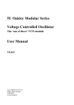
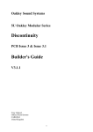
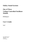
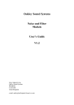
Oakley Sound Systems
5U Oakley Modular Series
Discontinuity
PCB Issues 2, 3 & 3.1
User Manual
V3.1.1
Tony Allgood
Oakley Sound Systems
CARLISLE
United Kingdom
1
A render of the suggested front panel design in a 2U wide 5U high MOTM format.
2
Introduction
This is the User Manual for the Discontinuity 5U module from Oakley Sound. This document
contains an overview of the operation of the unit and the calibration procedure.
For the Builder's Guides, which contain a basic introduction to the boards, a full parts list for
the components needed to populate the board or boards, and a list of the various
interconnections, please visit the main project webpage at:
http://www.oakleysound.com/discon.htm
For general information regarding where to get parts and suggested part numbers please see
our useful Parts Guide at the project webpage or http://www.oakleysound.com/parts.pdf.
For general information on how to build our modules, including circuit board population,
mounting front panel components and making up board interconnects please see our generic
Construction Guide at the project webpage or http://www.oakleysound.com/construct.pdf.
The prototype issue 2 module behind a natural finish Scheaffer panel in the MOTM format.
3
The Oakley Discontinuity
The Discontinuity is an updated version of an older Oakley module called the Wavefolder.
Both devices are voltage controlled waveshaper modules designed primarily for use in
modular analogue music synthesisers. The module comes in our standard 5U high 2U wide
format which is directly compatible with Synthtech's MOTM series.
The Discontinuity module, although using the same core technology as the old Oakley
Wavefolder, is different enough in circuitry, usage and front panel design to be worthy of a
new name. And it is the new discontinuity and offset controls and CV inputs that make this
module very unique.
Waveshaper modules work very differently to, and perhaps less intuitively than, other sound
shaping modules such as filters, ring modulators and amplifiers. As such the Discontinuity will
take some time to get used to. However, when used to process simple VCO waveforms it is
capable of creating some very beautiful tones, all of which can be varied dynamically in
musically interesting ways. Input waveform type, whether triangle, sawtooth or sine, can have
profound tonal differences in the Discontinuity's output. And varying the input level can also
have some amazing affects.
Internally the module is arranged as five sections connected in series.
1. The Soft Clipper.
This circuit gently restricts all input signals to around +/- 5.5 volts peak. It essentially mimics
an overdriven valve or tube amplifier. The output of this circuit passes directly to the next
stage which is...
2. The Clamper.
This prevents the output from going above or below a preset limit. Unlike the soft clipper
circuit the clamping is hard and abrupt. And unlike the soft clipper the limit is completely
voltage controllable. We call it the Threshold and it can be controlled with a front panel pot or
input CV. Any input can be altered dramatically with this function. As well as being passed on
to the next stage of the module, the output of clamper is available at its own output.
A three way toggle switch, called 'polarity' although not marked as such on the front panel,
offers three modes of clamping:
a) POS – the input signal is clamped when it exceeds the threshold voltage. ie. if the threshold
voltage is 2V, then all parts of the input signal that go above 2V will be clamped.
b) NEG – the input signal is clipped when it falls below the inverse of the threshold voltage. ie.
if the threshold voltage is 2V, then all parts of the input signal below -2V will be clamped.
c) BOTH – the switch is in its middle position. Both negative and positive clipping takes
place. ie. if the threshold voltage is 2V, then all parts of the input signal above 2V are
clamped, and all parts of the input signal below -2V are clamped.
4
In the old Wavefolder when the signal was clamped the output signal was simply held at the
threshold voltage. In the Oakley Discontinuity the output level during clamping can now be
varied dynamically. This can be done either as a function of the threshold voltage, via the
module's Discontinuity control and its CV input, or as a fixed offset with the Offset control
and its CV input. Furthermore, the offset can either be applied symmetrically or
asymmetrically depending on the Track/Oppose switch. What this means is that we can
actually remove any proportion of the original signal at that point where it exceeds the
threshold voltages and replace it with another input. In other words we can splice one
waveform in place of another. This has the potential to make some very new and wonderful
timbres.
The track/oppose switch controls whether the offset voltage is added to the output waveform
in a symmetrical or asymmetrical way. The switch's position only affects the negative part of
the input waveform. If in track then the offset voltage is applied equally to both the negative
and positive parts of the input waveform. ie. a 1V offset CV, with Discon set to 0%, will make
the part of the waveform that is replaced when the threshold is exceeded be both be 1V. In
Oppose mode, you have a 1V section in the positive part and -1V in the negative part of the
input waveform.
3. The Clipper.
What the Clamper bites off, the clipper returns. The Clip output is the part of the original
input signal that gets chopped off by the clamper circuit. So if you put a 5V peak triangle
waveform into the Clamper, set the threshold to be 2.5V and set the mode switch to BOTH,
the Clamp output will give you the neatly clipped almost square wave output, while the clipper
will give you the tips of the pointed bits of the original triangle waveform.
4. The Folder.
The Discontinuity's fourth section is based around a four quadrant multiplier. Here the Clip
out and Clamp out are mixed together. However, the clip output may be added or subtracted
from the clamped signal. A pot and an external CV sets the mix ratio and polarity. Again,
consider the 5V triangle waveform with the polarity switch set to either POS or NEG. With
the Fold pot set to 0, you get the plain Clamped signal at the main output. Turn the Fold pot
clockwise and the clipped signal will return to create the original signal once more. But keep
turning it, and the clipped signal is now bigger then the original. Now turn the pot the other
way. The clipped signal gets subtracted from the clamped signal. You can get full wave
rectification, thus your triangle becomes another triangle at twice the frequency.
Multiplication. Turn it up further and more harmonics come in.
5. The Amp.
The last stage is a simple x10 amplifier. The Discontinuity can clip accurately down to small
levels if you want, so you need a good amplifier to bring it up to a decent level again.
And don't forget the Discontinuity will work with any signal, audio and CV. You can mangle
EG outputs, LFOs and, of course, your VCO.
5
Power supply requirements
The design requires plus and minus 15V supplies. The power supply should be adequately
regulated. The current consumption is about +60mA for the +15V rail and -55mA for the
-15V rail. Power is routed onto the PCB by a four way 0.156” MTA156 type connector or the
special five way Synthesizers.com MTA100 header.
Power connections – MOTM and Oakley
The PSU power socket is 0.156” MTA 4-way header. This system is compatible with MOTM.
Power
Pin number
+15V
Module GND
Earth/PAN
-15V
1
2
3
4
The earth/pan connection has been provided to allow the ground tags of the jack sockets to be
connected to the powers supply ground without using the module’s 0V supply. Earth loops
cannot occur through patch leads this way, although screening is maintained. Of course, this
can only work if all your modules follow this principle.
Power connections – Synthesizers.com
The PWR power socket is to be fitted if you are using the module with a Synthesizers.com
system. In this case the PSU header is not fitted. The PWR header is a six way 0.1” MTA, but
with the pin that is in location 2 removed. In this way location 3 is actually pin 2 on my
schematic, location 4 is actually pin 3 and so on.
Power
Location number
Schematic Pin number
+15V
Missing Pin
+5V
Module GND
-15V
Not connected
1
2
3
4
5
6
1
2
3
4
5
+5V is not used on this module, so location 3 (pin 2) is not actually connected to anything on
the PCB.
If the PWR header is fitted then the small wire link LK should be fitted. This connects the
panel ground with the module ground.
6
How to Use this Module
As I have already mentioned waveshapers can be less intuitive than other synth modules. This
is especially true of the Discontinuity since it has several shaping functions available. In the
introduction I went through the various internal modules of the Discontinuity module, here I
will try to explain what each front panel control does in more detail.
The Polarity switch determines what part of the waveform is to be affected by the module. In
the POS position the module affects the positive parts of the input signal. That is all the parts
of the input signal that are above zero volts. Note that the module is completely DC coupled
this means that it will process slowly moving or even static control voltages as well as audio
signals. Figure 1 shows a triangular input waveform being clipped by the module.
Figure 1- Polarity set to POS showing basic clipping with threshold set to around 2V with no folding. The
slightly sloped flat part of the clipping is caused by the AC coupled input of the digital scope I have used to
make this picture and not the module itself
When the Polarity switch is put in the NEG position then the module will only affect the
negative portions of the input waveform. With the switch set to BOTH, its middle position,
both negative and positive parts of the waveform are affected.
Figure 2 – Polarity switch set to BOTH. Note both negative and positive parts of the input triangle wave input
have been clipped to produce a symmetrically clipped output waveform.
7
The Threshold pot is a manual control that sets the point when the input signal is to be
affected by the module. In figures 1 and 2 it is Threshold that sets the point at which the
clipping starts, ie. the point at which the input waveform starts to become deformed. The
Threshold value can be changed from around -7V to +7V with 0V being at the mid point. The
pot features a dead zone near the middle. This means that it is very easy to set the pot to
exactly 0V just by putting somewhere near the middle.
When the threshold voltage is set to say +2V, ie. slightly right of its centre point, the input
signal will be affected when it exceeds +2V if the Polarity switch is in either POS or BOTH,
and when it falls below -2V when the Polarity switch is in either NEG or BOTH. This part is
important to understand – the threshold pot will control both the negative and positive
threshold voltages simultaneously but its position shows the positive threshold voltage only.
The negative threshold voltage is always the inverse of the positive threshold voltage. For
example, if the positive threshold is 3V the negative will be -3V and so on.
Note: Setting the Polarity switch to BOTH and moving the threshold pot to 0V doesn't make
much sense since all signals above and below 0V will be clipped. ie. you'll get nothing.
However, this null result should also happen with any value of Threshold below 0V since how
can you have a signal that is both below -1V and above 1V? But Discontinuity does not obey
the laws of mathematics due to a quirk in the circuit topology. The output in this 'illegal' state
becomes a pulse wave whose height and width are determined by the Threshold pot. With a
triangle wave input and threshold values of just slightly negative the output will be a low
amplitude square wave. As you decrease the threshold value further the square wave will
narrow producing pulse wave of increasing amplitude. This behaviour was not originally
intended but it's quite a useful feature to have.
The Thresh CV pot controls the depth of the Thresh CV input. CV stands for control voltage
and this can come from any voltage source such as an LFO, VCO or ADSR. In this way the
threshold parameter can be varied automatically as if you were turning the Threshold pot
manually and proportionally to the input control voltage. With the Thresh CV pot at its
maximum value the threshold voltage will be equal to the input CV voltage.
Figure 3. Slight positive folding causing a soft clipping type of effect. Note the slightly rounded tips of the
triangle wave caused by the actions of the input soft clipping circuit.
8
With the Fold pot set to its middle dead band position the output is clipped at the level
determined by the Threshold pot and its input CV. The Fold pot however lets you control the
amount of the input signal that is allowed to return. At positions right of centre the input
signal is allowed to return with the same phase. This means that positive going parts of the
waveform are returned still going positive. The gain can be controlled by the Fold pot, with
zero in the middle, unity or 100% around two o'clock, and 200% at its maximum. Figure 3
shows this happening where we can see the top and bottom parts of the waveform having a
different gain to the middle parts. Look how the slope of the triangle wave is less at the points
compared to the bits crossing the middle horizontal 0V line.
It should be noted that when the fold pot is set the unity position, at around two o'clock, then
the Threshold and Discontinuity parts of the circuit are effectively switched off and the unit is
in a type of bypass mode. The output signal is more or less the same as the input signal.
With the Fold pot turned left of centre the phase of the returned input signal is switched. This
means positively going parts of the waveform are now negatively going. This means the
output waveform appears to fold back on itself. This can create frequency doubling effects as
the waveform now can cross the horizontal 0V line more often. Figure 4 shows the folding
action showing the tips of the input triangle wave being bent in opposite directions.
Figure 4. Folding with the Fold pot set to around -25% which is slightly left of its central position.
The Fold CV pot controls the depth of the Fold CV input signal. Like the Thresh CV, the
Fold CV input allows remote control over the fold parameter. Later on we will see that we
can use the Fold CV as the modulator input of a ring modulator.
The Discontinuity pot is probably unique in the world of modular synthesisers. Wave folding
modules of various sorts have been around for sometime. Indeed, our own Wavefolder
successfully introduced the technique to many people. The discontinuity mode is something
else though and comes in part from the actual way that the original Wavefolder did its wave
folding. When an input signal rises above the positive threshold voltage and/or below the
negative threshold voltage, the input signal is actually removed and the threshold voltages put
in its place. Now as we have seen the input signal, or a multiple of it, may then be returned by
the action of the Fold pot, but let us for the moment assume that the Fold pot is set centrally.
9
The Discontinuity pot controls that proportion of the threshold voltages that are replacing the
input signal. It can be varied from zero, ie. the replacement voltage is zero volts, to around
two, which is double that of the threshold voltage. The middle position of the Discontinuity
pot is calibrated to give unity. This means that at the middle position the replacement voltages
are exactly the same as the Threshold voltages, in other words, the traditional Oakley
Wavefolder action. As with the Fold and Threshold pots there is a dead zone built into the
pot's movement so it is easy to locate the unity position.
Figure 5 shows applying Discontinuity on a triangle wave. You can see the clipped sections
are no longer flat sections at the threshold voltage, but at lower voltages. In this case the
Discontinuity parameter is set to around 40%, that is around 9 o'clock on the front panel.
You should remember that the Discontinuity pot sets the multiple of the threshold voltage and
not the actual voltage itself. This means varying the Threshold pot will also vary the level of
the replacement voltages. When the Threshold voltage is set to 0V, ie. its middle position,
then varying Discontinuity will have no effect on the output signal. This is because 0V times
any number is still 0V.
Figure 5. Discontinuity on both negative and positive parts of the input waveform. Discontinuity is set at
around 40% of the threshold voltage.
The action of discontinuities in the waveform generate lots of high harmonics. These can be
seen in figure 5 as orange blurs on the leading edge of the discontinuity. These blurs are
actually reactions to the high frequencies inside the digital scope I have used to take these
pictures. They could have been easily removed with a little low pass filtering after the output
of the Discontinuity module. It's probably worth adding at this point that connecting any filter
post-waveshaping will give you an even greater range of sounds.
As with the other two front panel waveshaping pots the Discontinuity parameter can also be
varied with an external control voltage. The Discon CV pot controls the modulation depth of
a connected CV.
As we have seen the Discontinuity pot allows us to control the voltage that replaces the input
signal at that point when the threshold voltages have been exceeded. However, the
10
Discontinuity parameter is inherently tied to the threshold voltage set by the Threshold pot and
Thresh CV. The Discontinuity module also allows another control over the level of the
replacement voltage. This we call the offset and it's controlled by the Offset pot, its CV input
and a switch called Track/Oppose. The key difference between the Offset and the
Discontinuity parameter is that the Offset value is added (or subtracted) to the Threshold
voltage, while the Discontinuity parameter multiplies the Threshold voltage. The Offset
function and Discontinuity parameters can be used either on their own or together. This means
that the replacement voltage (or voltages) can be a mixture of both multiplied or added
Threshold voltages.
The Offset pot does one of two things. Firstly with no jack inserted into the Offset CV socket
it acts as a fixed voltage source. In its central position it produces 0V and no offset is added to
to the threshold voltages. At its furthest right it produces just under +4V, and at its furthest
left it produces -4V or so.
If you do not want any offset to be added you must ensure that the Offset pot is centralised.
The sensitivity of the pot is configured to be at its minimum near the centre of its travel. This
should make finding the zero point easier than a standard linear pot taper.
The Track/Oppose switch controls how the offset voltage is added to the threshold voltage to
give us the replacement voltages. In track mode, the offset voltage is added equally to the
negative and positive threshold voltages. This means that a 2V threshold and a -1V offset
voltage will produce a 1V replacement voltage for the positive part, and a -3V replacement
voltage for the negative part. This is because 2 + (-1) = 1, and -1 + (-1) = -2. You can see
this in figure 6.
Figure 6. Track mode showing a negative offset voltage making both replacement voltages move downwards.
In Oppose mode the two offset voltages move in opposite directions. This means that the
offset voltage is added to the positive threshold voltage to create the positive replacement
voltage, while the offset voltage is subtracted to the negative threshold voltage to create the
negative replacement voltage. This creates an offset voltage that creates a symmetrical
discontinuity to the input waveform. Taking the above example, a threshold voltage of 2V and
an offset voltage of -1V will give a 1V positive replacement voltage and a -1V negative
replacement voltage. Since 2 + (-1) = 1 and -2 - (-1) = -1.
11
You may have noticed that the positive replacement voltage is not affected by the
Track/Oppose switch. Indeed, only the negative parts are affected by the offset switch's mode.
Remember too that if your polarity switch is in the POS position you'll not notice anything
either.
The wide range of the offset pot allows you to create negative positive replacement voltages
and positive negative replacement voltages. In other words this is another way, besides the
Fold pot, when you can actually reverse the polarity of the input waveform when the threshold
voltages are exceeded.
The Offset CV input is a standard CV input. Once inserted a jack will remove the internal
connection to the Offset pot's voltage source. The Offset pot will function now as a standard
reversible attenuator to the CV input. This will produce maximum gain in the right hand
position with a gain of around +80% and a maximum gain of -80% to the left. The + and –
percentages indicate that the pot can also control the phase of the input signal with inversion
of the input signals to the left and in phase signals to the right. Middle position is zero meaning
that the effects of the CV input are turned off.
When the Discontinuity pot is turned fully left then the threshold voltage has no effect on the
replacement voltages. This means that the Offset pot or CV has complete control over the
output waveform when the threshold voltages are exceeded. With the Track/Oppose switch in
Track module it is therefore possible to splice one waveform into another. If you use an audio
signal into the Offset CV input then this signal will replace the input signal when the input
exceeds the threshold voltages. Using the threshold pot one can 'crossfade' the input waveform
with the offset waveform. It is not like analogue crossfading so expect some very interesting
results.
The Volume pot is a simple output level control. It is configured to have a gain of 10 which
allows you to clip signals down very small and then boost them up again to suit the usual +/5V signals that any connected modules are expecting. It should be noted that the maximum
output of the Discontinuity module is around +/-12V. So if you try to boost too much you'll
get clipping at +/-12V. It won't damage the module – but it might hurt your ears!
12
Calibration Procedure
There are four calibration trimmers in this module; two 6mm and two multiturn types. They
should be adjusted in the order given here. It is most useful to use a trimmer tool with the
multiturn trimmers. Spectrol and others make trimmer adjusters for less than a pound. But
remember don’t use the little adjuster as a normal screwdriver, you’ll break it.
The power supply voltages will slightly affect the calibration settings, particularly the two
offset adjustments. The effect is minor though and it is unlikely that any further calibration
should be required if you use the module with another power supply unless it is has
substantially different output voltages. However, I do recommend that you allow both the
module and the power supply to warm up before making any adjustments to the trimmers.
In all of these adjustments it is important to ensure that your knobs are aligned correctly. That
is, when the pointer is pointing upward the pot is indeed at its central point. The position of
the TRK/OPP switch has no effect on the setting up.
1. OFF2
This adjusts the offset of the VCA in the ring modulator and thus how much Fold CV breaks
through into the audio output. Set the Threshold, Fold and Volume pots to their maximum
settings. Set the Discontinuity and Offset pots to their middle positions. Set the Polarity switch
to its mid-point. All other pots should be set to their minimum positions. Adjust OFF2 until
the front panel LED is completely extinguished. On either side of the optimum position the
LED will glow either red or green.
2. ZERO
This adjusts the central point of the Fold pot. Put the Discontinuity into ring modulator mode
– ie. Threshold and Discontinuity pots set to minimum, Fold and Offset pots to their middle
position. The Volume pot should be at its maximum setting. All other pots should be at their
minimums. Connect a triangle wave source to the main input of the module and listen again to
main output. Adjust ZERO until the sound you hear is minimised. Check that rotating the Fold
pot just a little beyond its mid point, on either side, brings back the sound.
3. OFF1
This one needs a voltmeter; a decent digital one is best and it should be able to measure down
to within 10mV. You will be measuring the voltage with respect to ground. This means that
the negative probe needs to be connected to ground or 0V. The easiest point to access ground
is the top pad of LK near the bottom of the board. Set the Offset, Fold and Threshold pots to
their mid points. Set Discontinuity to full. Set all other pots to their minimum. Measure the
voltage at pin 7 of U13 – this is down the bottom of the board near the UNITY trimmer.
Adjust OFF1 until the voltage gets as close to zero volts as you can get it. It's a bit fiddly but
anything between +/-10mV (+/-0.01V) is fine.
13
4. UNITY
This is the difficult one to set up, but it's not going to blow up if you don't get it right so don't
worry about it too much. If you have an oscilloscope then this will help, but if not, you can set
it up by ear. After all, this is part of a musical instrument. The object of UNITY is to set the
mid point of the Discontinuity pot. Set this right and when Discontinuity is set to its middle
position the output waveform will not have any discontinuities and be simply clipped or
folded.
Set Fold, Offset, Discontinuity and Volume to their middle positions. Set the polarity switch
to its middle position. All other pots can be set to their minimum positions. Connect a sine
wave to the input of the module and listen to the output. Alter the Threshold until the sound
you hear resembles a square wave – a hollower sound, as opposed to the smooth sine wave
tone. This will be when the Threshold pot is set to around two o'clock. Now adjust the
UNITY trimmer until you find a point that seems more hollow than reedy. You'll find either
side of this point will be more buzzy and harsh.
If you have a scope you'll see your waveform has a neat flattened top. Moving UNITY beyond
its optimum point will give the waveform sharp pointy edges and the flattened part will either
be below or above the threshold point.
14
Final Comments
I hope you enjoy using the Oakley Discontinuity.
If you have any problems with the module, an excellent source of support is the Oakley Sound
Forum at Muffwiggler.com. Paul Darlow and I are on this group, as well as many other users
and builders of Oakley modules.
If you have a comment about this user manual, or have a found a mistake in it, then please do
let me know.
Last but not least, can I say a big thank you to all of you who helped and inspired me. Thanks
especially to all those nice people on the Synth-diy and Analogue Heaven mailing lists and
those at the Muffwiggler.com forum.
Tony Allgood at Oakley Sound
Cumbria, UK
© June 2012 – updated September 2013
No part of this document may be copied by whatever means without my permission.
15