1
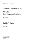
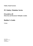
Oakley Sound Systems
5U Oakley Modular Series
COTA
Voltage Controlled Filter
PCB Issue 2
Builder's Guide
V2.0.1
Tony Allgood B.Eng PGCE
Oakley Sound Systems
CARLISLE
United Kingdom
Introduction
This is the Project Builder's Guide for the issue 2 COTA 5U module from Oakley Sound. This
document contains a basic introduction to the board, a full parts list for the components
needed to populate the boards, a list of the various interconnections and a 'how it works'
section.
For the User Manual, which contains an overview of the operation of the unit and the
calibration procedure, please visit the main project webpage at:
http://www.oakleysound.com/cota.htm
For general information regarding where to get parts and suggested part numbers please see
our useful Parts Guide at the project webpage or http://www.oakleysound.com/parts.pdf.
For general information on how to build our modules, including circuit board population,
mounting front panel components and making up board interconnects please see our generic
Construction Guide at the project webpage or http://www.oakleysound.com/construct.pdf.
2
The COTA PCB
The issue 2 prototype COTA in a 1U MOTM format panel with Schaeffer's natural finish. Note the use of
the Sock8 socket board to make wiring so much easier and quicker.
I have provided space for the three main control pots on the PCB. If you use the specified
pots and brackets, the PCB can be held firmly to the panel without any additional mounting
procedures. The pot spacing is 1.625” and is the same as the vertical spacing on the MOTM
modular synthesiser. The pots are; cut off frequency, resonance and frequency CV depth.
The design requires plus and minus 15V supplies. The power supply should be adequately
regulated. The current consumption is about 20mA for each rail. Power is routed onto the
main PCB by either a four way 0.156” MTA156 type connector or the special five way
Synthesizers.com MTA100 header. You could, of course, wire up the board by soldering on
wires directly. The four pins are +15V, ground, earth/panel ground, -15V. The earth/panel
connection allows you to connect the metal front panel to the power supply’s ground without
it sharing the modules’ ground line. More about this later.
This unit will also run from a +/-12V supply with a slight reduction in dynamic range.
The PCB has four mounting holes for M3 bolts, one near each corner. These are not required
if you are using the pot brackets.
The board size is 112mm (deep) x 104mm (high).
The main board has been laid out to accept connection to our Sock8 socket board. This small
board speeds up the wiring of the six sockets and reduces the chances of building mistakes.
3
Parts List
For general information regarding where to get parts and suggested part numbers please see
our useful Parts Guide at the project webpage or http://www.oakleysound.com/parts.pdf.
The components are grouped into values, the order of the component names is of no particular
consequence.
A quick note on European part descriptions. R is shorthand for ohm. K is shorthand for kiloohm. R is shorthand for ohm. So 22R is 22 ohm, 1K5 is 1,500 ohms or 1.5 kilohms. For
capacitors: 1uF = one microfarad = 1000nF = one thousand nanofarad.
To prevent loss of the small ‘.’ as the decimal point, a convention of inserting the unit in its
place is used. eg. 4R7 is a 4.7 ohm, 4K7 is a 4700 ohm resistor, 6n8 is a 6.8 nF capacitor.
Resistors
1% 0.25W metal film types are to be recommended simply because they are better quality
components. However, 5% ones can be used in all places if you wish. R23 will probably have
to be a 5% type since getting hold of a 1% metal film resistor in this value is sometimes not
trivial.
NOTE: The Filter Core format does not need R11 and R20 so these parts can be omitted if
you are building the 1U version of the filter.
100R
470R
1K
1K +3000ppm/K PTC
4K7
15K
33K
47K
68K
75K
100K
120K
150K
220K
240K
560K
1M
1M5
R14
R35
R7, R26, R46, R45, R36, R8, R27, R39, R52, R51, R40
R33
R15
R9, R2, R1, R28, R19, R18, R41, R48, R53, R47
R32
R10
R24, R37, R49
R42, R29, R55
R6, R4, R3, R16, R20, R25, R38, R50
R31
R12, R11, R13, R44, R34, R30, R54
R5, R21
R43
R17
R22
R23
4
Capacitors
330pF *
100nF, 63V axial ceramic
470nF,63V polyester
1uF, 63V polyester
2.2uF, 25V electrolytic
C1, C6, C8, C16
C5, C3, C13, C12, C10, C11, C4
C2
C9, C17, C7
C14, C15
* The 330pF should be a good quality capacitor such as silver mica, polypropylene or
polyester. The lead spacing is 5mm or 0.2”.
Discrete Semiconductors
1N4148 signal diode
BC550 NPN transistor
BC560 PNP transistor
J201 N channel JFET
D1, D2
Q4
Q3
Q1, Q2, Q5, Q6
Integrated Circuits
LM13700 dual OTA
TL072 dual op-amp
LF412A dual op-amp
U2, U4
U1
U3, U5
Trimmers
100K multiturn trimmer
20K multiturn trimmer
10K horizontal 6mm trimmer
TUNE
V/OCT
RES
Potentiometers (Pots)
All pots Alpha 16mm PCB mounted types
47K or 50K linear
10K linear
CV1-DEPTH, FREQUENCY
FEEDBACK
Two 16mm pot brackets.
5
Miscellaneous
Leaded axial ferrite beads
L1, L2
MTA156 4 way header
MTA100 6-way header
PSU
PWR
– Oakley/MOTM power supply
– Synthesizers.com power supply
Molex/MTA 0.1” header 6-way
Molex/MTA 0.1” housing 6-way
UPR
UPR
– for connecting to sockets
– for connecting to sockets
Molex/MTA 0.1” header 8-way
Molex/MTA 0.1” housing 8-way
LWR
LWR
– for connecting to sockets
– for connecting to sockets
Other Parts Required
Switchcraft 112APC 1/4” sockets
Eight off mounted either on the Sock8 board or on panel
Three 27mm knobs.
At least one cable tie to hold Q3 and Q4 together.
Around 2m of insulated multistrand hook up wire for the switch and socket connections.
Additional components required if using optional Sock8 board
Molex/MTA 0.1” header 6-way
Molex/MTA 0.1” header 8-way
UPR
LWR
Molex/MTA 0.1” housing 6-way
Molex/MTA 0.1” housing 8-way
UPR
LWR
112APC Switchcraft 1/4” socket
SK1, SK2, SK3, SK4, SK5, SK6, SK7, SK8
If using Molex KK you'll also need at least 28 crimp terminals.
Suitable lengths of wire to make up the two interconnects and three cable ties.
You need to fit a wire link in L1 on Sock8 issue 2 boards.
6
Additional parts required for the 2U version
You won't be needing the Sock8 board since all the sockets will need to be wired up
individually.
Make sure that R11 and R20 are fitted.
Miscellaneous
1/4” sockets
IN3, 1V/OCT
Offboard Pots (2U format only)
47K or 50K Log
47K or 50K Linear
IN1, IN2, IN3
CV2
Close up of the board showing the two bipolar transistors coupled together with a cable tie. You could use
some thermal paste between them. This would thermally couple the two devices even closer but it is
probably not worth it for this application.
Note also R33. This is the small temp co (positive temperature coefficient or PTC) resistor.
7
Connections
Power connections – MOTM and Oakley
The PSU power socket is 0.156” Molex/MTA 4-way header. Friction lock types are
recommended. This system is compatible with MOTM systems.
Power
Pin number
+15V
Module GND
Earth/PAN
-15V
1
2
3
4
Pin 1 on the I/O header has been provided to allow the ground tags of the jack sockets to be
connected to the powers supply ground without using the module’s 0V supply. Earth loops
cannot occur through patch leads this way, although screening is maintained. Of course, this
can only work if all your modules follow this principle.
Power connections – Synthesizers.com
The PWR power socket is to be fitted if you are using the module with a Synthesizers.com
system. In this case you should not fit the PSU header. The PWR header is a six way 0.1”
MTA, but with the pin that is in location 2 removed. In this way location 3 is actually pin 2 on
my schematic, location 4 is actually pin 5 and so on.
Power
Location number
Schematic Pin number
+15V
Missing Pin
+5V
Module GND
-15V
Not connected
1
2
3
4
5
6
1
2
3
4
5
+5V is not used on this module, so location 3 (pin 2) is not actually connected to anything on
the PCB.
If fitting the PWR header, you will also need to link out pins 2 and 3 of PSU. This connects
the panel ground with the module ground. Simply solder a solid wire hoop made from a
resistor lead clipping to join the middle two pads of PSU together.
8
Building the 1U Filter Core module using the Sock8 board
This is the simplest way of connecting all the sockets to the main board. The Sock8 board
should be populated in the way described in our construction guide found on the project
webpage. There are only two headers, UPR (for upper) which is six way, and LWR (for
lower) which is eight way. Both headers are fitted to the bottom side of the board.
If you have an issue 2 Sock8 board don't forget to fit a wire link in position L1.
You need to make up two interconnects. The six way one should be made so that it is 80mm
long. The eight way should be made to be 130mm.
The prototype unit showing the detail of the board to board interconnects. Here I have used the Molex KK
0.1” system to connect the Sock8 to the main PCB.
9
Building the 1U Filter Core module by wiring the sockets manually
If you have bought Switchcraft 112A sockets you will see that they have three connections.
One is the earth or ground tag. One is the signal tag which will be connected to the tip of the
jack plug when it is inserted. The third tag is the normalised tag, or NC (normally closed) tag.
The NC tag is internally connected to the signal tag when a jack is not connected. This
connection is automatically broken when you insert a jack.
Once fitted to the front panel the ground tags of each socket can be all connected together
with solid wire. I use 0.91mm diameter tinned copper wire for this job. It is nice and stiff, so
retains its shape. A single piece of insulated wire can then be used to connect those connected
earth tags to pin 1 of LWR. Pin 1 is the square solder pad.
All the other connections are connected to the signal lugs of the sockets. The tables below
show the connections you need to make:
UPPER
Pin
Pad name
Socket Connection
Lug Type
Pin 1
Pin 2
Pin 3
Pin 4
Pin 5
Pin 6
BP_OUT
Not connected
FBK_NC
FBK_IN
module ground
IN1
Connect to BAND PASS
Signal lug
Connect to FEEDBACK
Connect to FEEDBACK
Connect to IN1 & IN2
Connect to IN1
NC lug
Signal lug
NC lugs
Signal lug
LOWER
Pin
Pad name
Socket Connection
Lug Type
Pin 1
Pin 2
Pin 3
Pin 4
Pin 5
Pin 6
Pin 7
Pin 8
Panel ground
LP_OUT
1V/OCT_IN
2P_LP_OUT
module ground
IN2
module ground
CV1_IN
Connects to all sockets
Connect to -24dB/OCT
Connect to 1V/OCT
Connect to -12dB/OCT
Connect to 1V/OCT
Connect to IN2
Connect to CV1
Connect to CV1
Ground lugs via wire frame
Signal lug
Signal lug
Signal lug
NC lug
Signal lug
NC lug
Signal lug
10
2U COTA full format
I am not going into great detail with this format as the PCB has been primarily designed with
the 1U filter core module in mind. However, I will mention a few things that may be useful to
you if you do decide to build the larger format design.
The 2U format contains ten sockets and four additional pots. You can use any pots you like,
but I am rather partial to the 16mm Alpha pots sold by Banzai which have the solder lugs and
not the usual PCB mounted ones you have used on the board. You may be tempted to use the
larger 24mm Alpha pots, indeed, these are great pots, but the width of them may mean that
the top pot will clash with your choice of mounting rail.
Your first job will be to ground the earth lugs on each socket. Do this by joining the earth lugs
of each vertical row of sockets together first with stiff single core wire. Then use another
piece of solid core wire, going across horizontally, to connect all four vertical wires together.
Take a single insulated piece of wire back to on the PCB and connect it to pin 1 of the header
LOWER. This now connects all the sockets' ground lugs to earth/pan connection on the PCB.
This in turn goes, via pin 3 of the PSU header, back to the power supply.
It is also advisable to ground the NC lugs of the six input sockets too. Do this in much the
same way as you have 'commoned' the earth lugs. Simply connect all three sockets' NC lugs in
each of the right hand columns together with two pieces of stiff wire. Then, with two more
short lengths of insulated multistrand wire, connect the stiff wire pieces to pins 5 and 7 of
LOWER respectively.
The connections of the signal lugs of the CV and audio output sockets that go directly to the
PCB are summarised below:
UPPER
Pin
Pad name
Socket Connection
Lug Type
Pin 1
Pin 2
Pin 3
Pin 4
Pin 5
Pin 6
BP_OUT
Not connected
FBK_NC
FBK_IN
Module ground
Not connected
Connect to BAND PASS
Signal lug
Connect to FEEDBACK
Connect to FEEDBACK
NC lug
Signal lug
11
LOWER
Pin
Pad name
Socket Connection
Lug Type
Pin 1
Pin 2
Pin 3
Pin 4
Pin 5
Pin 6
Pin 7
Pin 8
Panel ground
LP_OUT
1V/OCT_IN
2P_LP_OUT
module ground
Not connected
module ground
CV1_IN
Connects to all sockets
Connect to -24dB/OCT
Connect to 1V/OCT
Connect to -12dB/OCT
See text
Ground lugs via wire frame
Signal lug
Signal lug
Signal lug
NC lugs
See text
Connect to CV1
NC lugs
Signal lug
All your other connections will be made via the four two way 0.1" headers that are situated on
the board near the pots. These are labelled appropriately to help you connect up your module
correctly. They are IN-1, IN-2, IN-3 and CV2.
Pots have three pins. Two of these pins will be connected to PCB, whilst the remaining one
will be connected to the appropriate socket's signal lug.
The middle pin of the pot, the wiper, will carry the signal to the appropriate header on the
PCB. The pots' wires will attach to the underside of the board at each header, and thus be
soldered from the topside of the board. For each header, pin 1 is connected to the wiper of the
pot. Pin 1 is the square pin so it is easily spotted even from the underside of the board.
The pot has two other pins, one will be connected to ground, the other to the signal lug on the
socket it controls.
With pins facing down and looking at the back of the pot, the right hand pin should go to the
ground connection of the header, that is pad 2 on each of the headers. Take a wire from the
right hand pin to the round pad on the PCB next to the one that the associating wiper
connects.
Now each pot will have one unsoldered pin left. Connect these to the appropriate socket. The
wire should go to the signal lug of the socket. IN 1 goes to the signal lug on the socket
labelled IN 1, and so on.
There are a quite lot of wires here, but it should be quite neat once it is all done.
12
Circuit description
The design of the Oakley Cascaded Operational Transconductance Amplifier filter is very
traditional and I am making no claims for originality. The design topology is found in many
synthesizers. It is simply four voltage controlled low pass elements put in cascade to give us a
great sounding four pole low pass filter. Each low pass element is made from an integrator,
built from an OTA and a timing capacitor, a buffer of some sort, and some resistative
feedback. The active parts of the design were put into chip form as the SSM2040 (eg. Prophet
5 rev 2, Octave CAT SRM) , CEM3320 (eg. Prophet 5 rev 3 and Oberheim OB-Xa) and the
IR3109 (eg. Jupiter 8 and SH-101). Each one of these chips behaves differently in terms of
signal linearity, hence their different sounds, but the internal topology was much the same.
The Moog ladder can be thought of as a cascaded design too although this is constructed so
differently to warrant its own classification.
Roland initially used transistor Moog ladders and then diode ladders in their first synths like
the SH-3, SH-5 and SH-2000. However, later synths such as the SH-7, SH-1 and System 700
used a cascaded design built from CA3080s. The 3080 is an operational transconductance
amplifier, OTA, which is probably more commonly used as a VCA, but here it was used as the
control element in the integrator. Later Roland synths such as the SH-09 used their own
version of the CA3080, the BA662, as the OTA. Later still, the JP-8 and SH-101 used four
matched OTAs in one package complete with its own onboard exponential convertor, this was
the IR3109 filter chip. The fundamental sound was similar to the early more discrete design –
although there are some sonic differences between all the versions when you listen more
closely.
The Oakley design is a four stage filter that uses the well respected LM13700 as the OTA
element. There are two OTAs in one LM13700, and the two internal devices are quite
similarly matched. The OTA part of the LM13700 can be considered to be very similar to the
CA3080 and probably the OTA part of the BA662.
Before we look at the core in detail, we need first to have a look at how the signals are treated
before they reach the filter circuitry. There are three main audio inputs to the COTA, each one
has a two pin header with the second pin being used for a ground, or 0V, connection. These
are shown on the schematic as IN1, IN2 and IN3. Two of these inputs have an alternative
input solder pad – these are to be used in the 1U Filter Core module. These have no individual
ground since they will going straight to the input jack socket's signal lug.
U3 and its associating components form a inverting summing circuit. This common circuit
block is used to add the various input signals together. The gain of the summing is set to be
roughly a third. That is, if all three inputs are at 5V peak, the output at pin 1 of U3 will be
approximately 5V peak. Note though that it is an inverting summer, which means that the
phase of the summed output is in opposition to the input signals. This means a negatively
going signal will be converted to a positive going one.
C2 provides AC coupling of the audio output of the summer. This acts to block any DC or
very low audio frequencies. As we have seen the whole filter is built from four identical single
13
pole low pass filters. Each filter element is basically a current controlled integrator with some
negative feedback to provide the required low pass function.
Let us look at the first element in the signal chain, that is the one made based around U2a, Q1
and C1. The first element is identical to the others but does have some additional bits added to
allow for the resonance feedback input. We'll look at this particular bit in more detail later.
The OTA is very useful device. It produces an output current that is proportional to the
difference in voltage between its two inputs, pins 4 and 3. Furthermore, that output current is
also proportional to current drawn from a control pin, which is pin 1 for this integrator. This
control current is called Iabc - abc standing for 'amplifier bias current'.
In this application we can see that one of the inputs to the OTA is tied only to ground through
a low value resistor, R7. Thus our only voltage input is at pin 4 which is the inverting input.
This means that our output current is proportional, but of opposite polarity, to the voltage at
pin 4. That current is used to charge and discharge the timing capacitor, C1. The more
negative the input voltage, the faster the capacitor charges. The more positive the input
voltage the faster the capacitor discharges. This is the action of an integrator.
Remember too the affect of Iabc. This controls the output current too, and a bigger Iabc will
mean a faster rate of charging and discharging. Iabc is provided by the control voltage (CV)
input circuitry and we will look at this later, but at the moment we can simply think of Iabc
being larger for higher cut-off frequencies.
When you charge a capacitor up the voltage across it changes. It is this voltage that we are
interested in since this is what we want to hear. However, we can't just take this voltage from
the capacitor because by doing so we will steal current from it and affect the output level. So
we use a buffer made from a JFET, Q1, and a resistor, R9. This simple circuit allows us to
make a copy of the capacitor voltage without affecting that voltage itself. That copy is
presented at the source pin of the JFET. There's actually a small error in this copy, in that it is
slightly higher in value than that across the capacitor. However, this is no issue because the
error is constant and we're only interested in the audio part of the signal, the wiggly bit, and
not any constant DC term. C9, a largish value capacitor, will block the DC and allow the
audio through.
Note R6, this is critical to the operation of the low pass element. This passes back some of the
output signal back to the input. Actually, it is passing current back to the input and because it
is of opposite polarity to the input signal it acts against it and regulates the output. It is this
negative feedback that gives us our overall low pass filter response. Without R6, we just have
an integrator and the voltage across the capacitor would simply rise and rise with any positive
input voltage, or fall and fall with any negative signal. Of course, it can't rise or fall beyond the
limits of the power supply, but even so, it wouldn't give us the desired low pass effect.
I will point out one more thing about this feedback path. The value of the feedback resistor,
R6, in conjunction with the value of R5, sets the gain of the filter stage. Unlike many cascaded
OTA designs, this is not set to one. In other words, the Oakley COTA is unusual in that the
passband signal level changes as it runs through the filter. The first stage there is an gain of
approximately one half. This is to reduce the large signal levels coming out of the audio
summing circuit. Then the other three following stages have a gain of approximately 1.47.
14
This means that when the filter is put into self-oscillation the magnitude of the resultant sine
wave output is the same from each filter stage.
However, it also means that the audio level gets hotter as it works its way through the filter.
This means that any non-linearities in the circuits are going to be exacerbated as the signal
progressively gets closer to overdriving the sensitive OTA input circuitry. So why have I done
this because surely this is a problem? Over the years I have heard many different synthesisers
and some I like a lot, and some not so much. I analysed the circuits of one of my favourite
synths and wondered why this 1978 synth sounded better than those that followed it. One of
the differences was the filter gain structure and this one had been made for constant oscillation
levels, but the later synth designs had unity gain in each filter stage.
So what I have done for the COTA is copied the unusual gain structure from that wonderful
1978 synthesiser. So which synth is it? You'll have to guess.
You can of course change the values of R24, R37 and R49 to 100K to give each stage unity
gain. I found the basic sound to be much the same, but there was something smoother
sounding about the earlier circuit value. Why not experiment yourself?
As I have hinted earlier all OTAs are non linear. This means that they affect the input more
than they should and produce audible distortion at their outputs. Now the LM13700 features a
simple waveshaping circuit, based around some internal diodes, at each of its two inputs.
These waveshaping circuits produce their own non-linearities, but the shape of these non
linearities are designed to cancel out the other ones present in the rest of the chip. The
waveshapers are 'turned on’ by the presence of currents at pin 2 and pin 15. However, in this
design I have chosen not to utilise the diodes. This will decrease the overall signal to noise
ratio, ie. make the module more noisy, but it will allow the signal to gracefully overdrive. It
also makes it closer to the behaviour of the CA3080 and hence give the module a more classic
vintage tone.
The COTA has three audio outputs. The -12dB/octave output is taken from the output of the
second stage of filtering. The -24dB/octave output is taken from the final fourth stage. Both of
these are inverted and amplified by identical op-amp circuits, based around U3b and U5b
respectively. C7 and C17 provide AC coupling – allowing the audio to go through but
blocking the DC voltage output of the filter stages. The inversion of these stages is not a
problem since it simply reverses that was done by the audio input summing circuit, U3a. The
gain of each output stage is set to -2, so as to bring the output signal level, when the filter is
oscillating, to roughly 5V peak, or 10V peak to peak.
It should be noted that due to the non unity gain of each filter stage, the passband audio signal
does get larger as it works its way down the filter stages. Thus the -24dB/octave output will
be greater than the -12dB/octave output. It may not necessarily be louder though, since the
-12dB/octave output will be brighter in tone.
The bandpass output is a derived output and not generated in a true bandpass filtering process.
The fourth stage output is summed with the first stage output in a specific proportion. This
summing allows for the frequencies below the cut-off frequencies to be attenuated whilst
reinforcing those above it. This gives an eventual overall roll off of -6dB/octave above and
below the cut-off frequency.
15
The actual summing proportions were determined firstly mathematically and then verified
empirically. To create a bandpass output the mathematics tells us that the output of the first
and fourth filter stages shall be summed equally. However, the mathematics assumes that each
filter stage has a gain of unity - ours do not. Each of our filter stages is designed to produce an
equal output when oscillating and not for a unity gain in the passband. In practice this means
that each of our filter stages has the effective gain of around 1.47. Over the three stages, from
first to fourth, this means we have an overall gain of 3.18 or so. Thus R43 should be 3.18
times bigger than R42. If we choose R42 to be 75K, R43 should then be 238K. Using 240K is
the nearest real resistor value.
The feedback path is normally wired from the fourth output stage back to the input – although
the feedback input socket does allow you to change this. For the moment we will consider the
normalised route from the -24dB/octave output via the RES trimmer and R35 to the FBO
solder pad. This is then wired to the normalised lug of the feedback socket, which when no
jack is inserted, simply carries the signal back to the FBI solder pad. The amount of feedback
routed back to the input stage of the first filter element is controlled by the 'FEEDBACK' pot,
D1 and D2 act as voltage limiters preventing feedback runaway and ever increasing selfoscillation. R1 limits the input current and prevents these diodes from having a detrimental
effect on any input plugged into the feedback socket. Even so it should be noted that the
feedback input is quite low in impedance compared with the minimum value of 47K of
ordinary Oakley audio inputs. However, this should not cause any problems in practice.
Iabc is provided by Q3 which acts as an exponential convertor and voltage to current
convertor in one. It is driven by an emitter follower, Q4. Both transistors act together to
eliminate the effects of Vbe drift. Vbe drift, if uncompensated, would cause the filter’s cut off
frequency to change with temperature. However, any drift in Vbe in Q3, is effectively
cancelled out by an opposite drift in Q4. In theory, the transistors must be matched for Vbe.
However, this is not really necessary in my opinion.
Vbe drift is not the only source of inaccuracy in the exponential convertors. Drift in the scaling
factor caused by a changing ambient temperature can be cancelled by the PTC resistor R33.
The PTC resistor’s resistance goes up by 0.30% every degree C, and this almost compensates
for the -0.35% drift in scaling. It is not essential to get this exactly cancelled in a VCF, since
the imperfections create only a slight change in the tonal characteristics as the temperature
changes.
U1b acts a summing amplifier taking all the CV inputs together to create one CV line to
control the exponential convertor. V/OCT sets the relationship between the input voltage and
the affect on the cut-off frequency. It is normally trimmed so that an increase in 1V on the
KBD input will produce a one octave shift in cut-off frequency.
U1a and associating components act as a reversible attenuator. This is based on a simple but
very effective circuit. I first saw it in the classic text ‘The Art of Electronics’ by Horowitz and
Hill. They probably aren’t the originators of the circuit.
The best way to figure out how it works is to think what happens when the pot wiper (pin 2)
is moved to each of the ends. When the pot is turned fully counter clockwise, the wiper
connects to ground, pin 1. Thus, the non-inverting input to the op-amp is now connected to
16
ground. The pot has no effect on the circuit other than loading the input, which we can ignore.
One of the golden rules of op-amps is that both inputs must be at the same voltage. (This is
not actually true, but it is a useful starting point.) If the non-inverting input is at ground, then
so must the inverting input. A voltage at the input is turned into a proportional current
through R3, because one end is at ‘ground’. The op-amp acts in such a way as to produce the
same current through its feedback loop, namely R4. It does this by changing the voltage on
its output. Because the resistors are the same value, you need to have the same voltage but of
opposite sign appearing at the output of the op-amp to produce the same current. Thus the
op-amp is working as an inverting amplifier with a gain of -1. So if the voltage on CV1 was
3V, the output of U1a would be -3V.
Now, let us move the wiper to the opposite side, that is, fully clockwise. This one is harder to
figure out. This means that the non-inverting input is connected to the input signal. The golden
rule says that the inverting input is also at the same voltage. This means that no current flows
through R3. Why? Because you need a difference in voltage across a device to create a
current. So if there is no current through R3; there is none flowing through the feedback
resistor R4. To do this, the op-amp must produce the same voltage at its output as on its two
inputs. Thus the gain of the op-amp is +1. This means a +3V signal going in, ends up as a +3V
signal going out. I will leave it to you to prove that the central position of the pot gives no
output.
Power is supplied via the usual four way MTA/Molex connector or the five pin but six way
Dotcom power header. As is the custom for Oakley modules, I have used ferrite beads to act
as high frequency filters on the power lines. Decoupling at the point of entry is provided by
C12 and C14 for the positive rail, and C13 and C15 for the negative rail. Additional
decoupling is also provided elsewhere on the board by the other capacitors shown at the
bottom of the schematic. All these capacitors keep the power supply clean of noise, and
provide a reservoir for the little bursts of current that the circuit takes in normal operation.
17
Testing, testing, 1, 2, 3...
Apply power to the unit making sure you are applying the power correctly. Check that no
device is running hot. Any sign of smoke or strange smells turn off the power immediately and
recheck the polarity of the power supply, and the direction of the ICs in their sockets.
Assuming everything is OK so far, it is time to apply an audio input. Use a bright signal like a
sawtooth output from a VCO. Middle A, 440Hz is a good note to use.
Moving the FREQUENCY control should produce the usual and distinctive filter effect from
the -24dB/octave low pass output. From the -12dB/octave pass output, you should hear the
same sort of sound, but slightly brighter and more electronic in tone. It will also be slightly
quieter in volume than the -24dB/octave output. The band pass output should produce a sort
of wah-wah sound as the Frequency pot is moved back and forth. Turning the Resonance up
will accentuate the ‘electronic’ nature of the sound on all three outputs.
Remove the audio input and check that at just under maximum resonance the filter output will
oscillate across the whole audio band. Beware, it is quite possible to get this filter to oscillate
above the range of hearing. So be careful so as not to damage your studio monitor’s tweeters.
Listening to the -24dB/octave low pass output with the sawtooth input connected again, patch
a LFO or EG output to the CV inputs. The 1V/octave input should produce large sweeps of
cut-off. Check also that with the LFO or EG connected to the CV1 input, the CV1 pot allows
you to control the depth of the sweep. Fully clockwise the CV1 input should produce very
deep sweeps.
Notice that the minimum sweep depth should occur with the CV1 pot at its mid point. Use a
sawtooth waveform on your LFO, and see if the CV1 depth pot allows you to invert the
modulation input. You should get a ‘dow-dow-dow...’ from one side and a ‘yit-yit-yit...’ from
the other.
Check that both the audio inputs should behave identically.
If all this happens, the chances are that you have a working module.
18
Trimmers
There are three trimmers on the PCB.
V/OCT: This adjusts the scaling of the exponential inputs. Adjust this so that there is an
octave jump in cut-off frequency when the 1V/OCT input is raised by one volt.
Plug a 1V/octave source into the 1V/OCT socket. This may be your keyboard’s pitch CV
output, or from the CV output of a midi-CV convertor. Set the Resonance pot fully clockwise
to get the filter oscillating. Now listen to the output coming from the low pass output. I found
it is best to use the Frequency pot on the front panel to set the filter oscillating at quite a high
frequency tone. Somewhere around 880Hz (two As above middle C) will do. Now play a
note on your keyboard and then the same note an octave above. Repeat this again and again
and adjust the V/OCT trimmer to get the filter’s oscillations to jump an octave too. Don’t
worry about the actual pitch the VCF is producing. Just concentrate on getting roughly one
octave difference between the low note and the high note.
It is a fiddly adjustment and it takes a while to get it right. But remember that this is filter and
not a VCO, so you don’t have to be too accurate.
TUNE: This adjusts the filter’s cut-off frequency. Set this so that the filter’s FREQ pot covers
your chosen range. In a polyphonic modular, this is needed to make each voice’s VCF behave
identically.
The last trim to do is to set the RES trimmer. This allows you to set where you want the
resonance to occur as you turn up the Feedback pot. I normally make resonance start at
around three quarters of the way around.
Once that is completed the unit is ready to be used to make music.
19
Final Comments
If you have any problems with the module, an excellent source of support is the Oakley Sound
Forum at Muffwiggler.com. Paul Darlow and I are on this group, as well as many other users
and builders of Oakley modules.
If you can't get your project to work, then Oakley Sound Systems are able to offer a 'get you
working' service. If you wish to take up this service please e-mail me, Tony Allgood, at my
contact e-mail address found on the website. I can service either fully populated PCBs or
whole modules. You will be charged for all postage costs, any parts used and my time at
25GBP per hour. Most faults can be found and fixed within one hour, and I normally return
modules within a week. The minimum charge is 25GBP plus return postage costs.
If you have a comment about this builder's guide, or have a found a mistake in it, then please
do let me know. But please do not contact me or Paul Darlow directly with questions about
sourcing components or general fault finding. Honestly, we would love to help but we do not
have the time to help everyone individually by e-mail.
Last but not least, can I say a big thank you to all of you who helped and inspired me. Thanks
especially to all those nice people on the Synth-diy and Analogue Heaven mailing lists and the
Muffwiggler.com forums.
Tony Allgood at Oakley Sound
Cumbria, UK
© September 2008 – updated January 2015
No part of this document may be copied by whatever means without my permission.
20