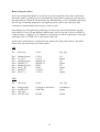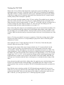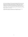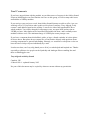
1
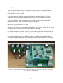
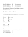
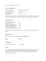
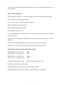
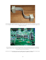
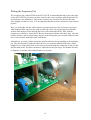
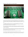
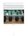
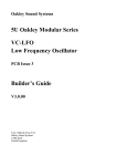
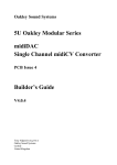
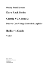
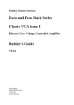
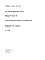
Oakley Sound Systems
5U Oakley Modular Series
Slim VCO B
SVCO issue 2 & Octave Board issue 1
Builder's Guide
V2.0.2
Tony Allgood
Oakley Sound Systems
CARLISLE
United Kingdom
Introduction
This is the Project Builder's Guide for the Slim Voltage Controlled Oscillator variant B
(SVCO-B) 5U module from Oakley Sound. This document is to be used with issue 2 main
boards and issue 1 octave boards.
In this document you will find a basic introduction to the board, a full parts list for the
components needed to populate both boards and a list of the various interconnections.
For the User Manual, which contains an overview of the operation of the unit and the
calibration procedure, please visit the main project webpage at:
http://www.oakleysound.com/s-vco.htm
Also on the SVCO webpage is all the documentation for the SVCO-A variant. The A version
is similar to the B version but lacks the octave and LFO switching.
For general information regarding where to get parts and suggested part numbers please see
our useful Parts Guide at the project webpage or http://www.oakleysound.com/parts.pdf.
For general information on how to build our modules, including circuit board population,
mounting front panel components and making up board interconnects please see our generic
Construction Guide at the project webpage or http://www.oakleysound.com/construct.pdf.
The first ever SVCO-B fitted behind a natural finish Schaeffer panel. This is an issue 1.1 SVCO main
board and issue 1 Octave Board.
2
The issue 2 Slim VCO & issue 1 Octave Board
On the SVCO printed circuit board I have provided space for the four main control pots. If
you use the specified 16mm Alpha pots and matching brackets, the PCB can be held very
firmly to the panel without any additional mounting procedures. The pot spacing on this board
is different to many of our other 5U modules, instead of 1.625” it is 1.375”. Used in
conjunction with smaller 20mm diameter knobs this still allows for an attractive module design
and finger friendly tweaking.
The design requires plus and minus 15V supplies. The power supply should be adequately
regulated. The current consumption for the whole SVCO-B module is about +47mA and
-38mA. Power is routed onto the main PCB by either our standard four way 0.156” MTA156
type connector or the special five way Synthesizers.com MTA100 header.
The octave board takes its power directly from the main SVCO board via a 10-way ribbon
cable. This ribbon cable also carries the reference voltage used by the octave board, the wiper
voltage from the frequency pot and a voltage that controls the pitch of the SVCO.
The main PCB has four mounting holes for M3 bolts, one near each corner. These are not
required for panel mounting if you are using the three 16mm pot brackets. The main board
size is 109mm (deep) x 123mm (high) and the octave board is 86mm (deep) 93mm (high). The
Octave board sits above the main board on three 25mm hex threaded spacers.
The Slim-VCO board has been laid out to accept connection to our Sock6 socket board. This
small board speeds up the wiring of the six sockets and reduces the chances of building
mistakes.
The 10-way IDC interconnect carries signals and power between the octave board and the main board.
You can also see the side adjustable trimmers on the main board.
3
SVCO-B Parts Lists
Note that this is the parts list for the SVCO-B module and not the SVCO-A. The simpler A
version has its own Builder's Guide and this should be used if you are building the A version.
The SVCO-B module is made from two PCBs; the main board and the daughter board. The
proper name for the main board is Slim-VCO, and the daughter board, Slim-VCO Octave
Board.
Issue 1 Octave boards are designed to sit above issue 1.1 or 2 Slim-VCO boards. The earlier
issue 1 Slim-VCO boards cannot be used with the Octave boards.
For general information regarding where to get parts and suggested part numbers please see
our useful Parts Guide at the project web page or http://www.oakleysound.com/parts.pdf.
The components are grouped into values, the order of the component names is of no particular
consequence.
A quick note on European part descriptions. R is shorthand for ohm. K is shorthand for kiloohm. R is shorthand for ohm. So 22R is 22 ohm, 1K5 is 1,500 ohms or 1.5 kilohms. For
capacitors: 1uF = one microfarad = 1000nF = one thousand nanofarad.
To prevent loss of the small ‘.’ as the decimal point, a convention of inserting the unit in its
place is used. eg. 4R7 is a 4.7 ohm, 4K7 is a 4700 ohm resistor, 6n8 is a 6.8 nF capacitor.
Slim-VCO issue 2 Parts List
Resistors
1% 0.25W or 0.4W metal film resistors are recommended.
Not all resistor spaces are filled up. These are for use with the expansion port. For the
standard SVCO-B module R18, R30, R39, R42, R63 and R65 should be left empty.
1K
2K2
3K6
3K9
7K5
9K1
10K
15K
22K
27K
30K
39K
47K
R41, R4
R38
R37
R44
R6
R3
R32, R60, R46, R47
R5, R64, R62, R59, R61
R19, R35, R40, R50, R51, R22, R20
R10
R7
R26, R9, R34
R0, R2, R21, R23, R43
4
68K
75K
100K
150K
220K
300K
680K
1M
R15
R8, R31, R28
R13, R71, R16, R68, R29, R48, R24, R57, R69, R55, R67, R66, R58,
R54, R52, R53, R56, R70, R17, R1, R11
R36
R49
R25
R14
R27, R33, R45
Oakley/MOTM systems:
120K
R12
Synthesizers.com systems:
180K
R12
1K 1% KRL temp co PTC (mounted on top and in contact with U6)
Capacitors
100nF axial ceramic
4p7 C0G 2.5mm ceramic
100pF C0G 2.5mm ceramic
150pF C0G 2.5mm ceramic
470pF C0G 2.5mm ceramic
1nF C0G 2.5mm ceramic
2u2, 35V electrolytic
C16, C4, C6, C1, C8, C7, C5, C18, C3, C11, C19, C9,
C17, C2
C12
C15
C13
C10
C14*
C20, C21
* Alternatively 50V or 63V radial polystyrene can be used but these tend to be much larger
devices so do check that it will fit.
Discrete Semiconductors
1N4148 signal diode
5V6 zener diode
2SK30A-GR Japanese JFET
BC550 NPN small signal transistor
BC560 PNP small signal transistor
D3, D4, D5, D6, D7, D8, D9
D1, D2
Q3
Q1, Q2, Q4
Q5
Integrated Circuits
THAT300 NPN array
U6
CA3130EZ single MOSFET op-amp U7, U8
5
TL072CN dual FET op-amp
TL074CN quad FET op-amp
LM4040DIZ-10.0 10V reference
LT1013CP dual precision op-amp
U5
U4, U9
U1*
U2, U3
* The LM4040CIZ-10.0 is also suitable.
IC sockets are to be recommended. You need five 8-pin and three 14-pin DIL sockets.
Trimmers (preset) resistors
All are multiturn cermet types with side adjustment screws. Note: this is different than most
Oakley modules which use top adjustment screws. On this module, because of the placement
of the octave board, you must be able to have access the screws from the side of the module.
That is, fit the screws so that they face towards the top of the board.
10K
100K
20K
HFT, SCL
TUN
OCT
Potentiometers (Pots)
Alpha 16mm PCB mounted types:
47K or 50K linear
EXPO_CV, SHAPE, SHAPE_CV
Alpha 16mm panel mounted with solder tag of type:
47K or 50K linear
TUNE – Not soldered directly to the PCB. See later.
Three 16mm pot brackets.
All four pots can be PCB mounted types if this is all you can get. However, since the TUNE
pot will be mounted slightly above the board then it may be preferable to use a pot with a
solder tag connection to allow for simpler wiring.
Miscellaneous
Leaded axial ferrite beads
L1, L2
2 x 5 way 0.1” box header
OCTAVE_BRD
MTA156 4 way header
MTA100 6-way header
PSU
PWR
– Oakley/MOTM power supply
– Synthesizers.com power supply
Molex/MTA 0.1” header 3-way
BUSS
– for connecting to Oakley CV/gate buss
6
Molex/MTA 0.1” header 8-way
Molex/MTA 0.1” housing 8-way
UPR
UPR
– for connecting to sockets
– for connecting to sockets
Molex/MTA 0.1” header 4-way
Molex/MTA 0.1” housing 4-way
LWR
LWR
– for connecting to sockets
– for connecting to sockets
If not connecting to the Oakley Buss then you will also need a 0.1” jumper to short out pins 1
and 2 on the BUSS header. If you are going to be using the Oakley Buss you will need the
usual 3-way KK/MTA housings for your connecting cable. See section on the Oakley Buss in
the User Manual for the SVCO.
Slim-VCO Octave Board issue 1 Parts List
Resistors
1% 0.25W or 0.4W metal film resistors are recommended. However, the four 6K8 resistors
must be 0.1% 0.4W metal film or better.
100R
1K
6K8, 0.1%
10K
20K
22K
47K
75K
100K
220K
R10
R9
R15, R17, R21, R22
R1, R4
R19
R11, R12, R20
R14, R16, R23
R13
R5, R6, R7, R8, R24
R2, R3
Oakley/MOTM systems:
270K
R18
Synthesizers.com systems:
100K
R18
Capacitors
100nF axial ceramic
1nF, 63V polyester film box
100nF, 63V polyester film box
1uF, 35V electrolytic low profile
2u2, 35V electrolytic low profile
4u7, 16V electrolytic low profile
C1, C10, C11, C12, C13, C14, C15, C16, C17
C4, C5
C2, C3
C18
C6, C7
C8
7
10u, 35V electrolytic low profile
C9
Discrete Semiconductors
1N4148 signal diode
BAT-42 schottky diode
3mm green LED
3mm orange LED
D2, D3, D4, D5, D7, D8
D1, D6
2”, 4”, 8”, 16”, 32”
LO
You can use any colour LEDs you like. But if you really have to use blue ones then you'll
probably need to increase the value of R9 to reduce the current and therefore the brightness.
Integrated Circuits
74HC14 hex schmitt trigger
74HC138 decoder
74HC192 up/down counter
DG408 1 to 8 analogue switch
78L05 100mA 5V regulator
TL072CN dual FET op-amp
LT1013CP dual precision op-amp
U3
U1
U2
U5
U4
U6
U7
IC sockets are to be recommended. You need two 8-pin, one 14-pin and three 16-pin DIL
socket.
Trimmer resistors
All are multiturn cermet types with the usual top adjustment screws.
5K
100K
OCT2
LOF
Miscellaneous
2 x 5 way 0.1” box header
SVCO_BRD
Switch
One single pole ON(mom)-OFF-ON(mom) toggle switch is required for the octave selection.
These are the type that are spring loaded so that the toggle naturally sits in the middle
position. The switch will not stay in the up or down position and because of this they are
called momentary switches.
8
The switch is mounted on panel and wired to the octave board with very short fly wires – see
later for details.
Other Parts Required
Six Switchcraft 112APCX 1/4” sockets mounted either on the Sock6 board or on panel
One 27mm knobs and three 20mm knobs.
Two 2 x 5 (10-way) 0.1” IDC female box connector.
Three 25mm M3 hex threaded spacers
Six M3 nuts and shakeproof washers
Six 12mm M3 machine screws.
A very small length of 10-way 0.05” IDC cable. You can cut down larger width to make 10
way if you need to.
A small amount of thermally conducting paste can be useful to help bond the PTC and U6
together.
Around 2m of insulated multistrand hook up wire for the socket connections.
Thin solid core wire for the frequency (TUNE) pot and switch connections.
Components required if using optional Sock6 board
Molex/MTA 0.1” header 8-way
Molex/MTA 0.1” housing 8-way
UPR
UPR
Molex/MTA 0.1” header 4-way
Molex/MTA 0.1” housing 4-way
LWR
LWR
112APC Switchcraft 1/4” socket
SK1, SK2, SK3, SK4, SK5, SK6
L1 on the Sock6 PCB is not to be fitted.
If using Molex KK you'll also need at least 24 crimp terminals.
Suitable lengths of wire to make up the two interconnects and four cable ties.
9
The 10-way IDC (insulation displacement cable) interconnect that connects the two boards. Use a bench
vice to clamp the connectors onto the ribbon cable. Ensure that the connectors are fitted the right way so
that pin 1 goes to pin 1.
A close up of the VCO core on the SVCO main board. Note the positioning of the positive temperature
coefficient (PTC) resistor. The PTC straddles U6 and a small amount of thermal paste can be used to
keep them both at the same temperature.
Note also C14. In this prototype I have used a radial polystyrene capacitor. Although this one fits just fine
a much smaller C0G ceramic capacitor would have been neater.
10
An important note about mounting the pots
Normally it doesn't matter too much whether the PCB is mounted exactly at right angles to the
front panel on an Oakley module. However, for the SVCO-B you need to be more careful.
The SVCO-B uses two PCBs and that takes up more room. This means there is not so much
room between the octave board's components and the PCB (or its mounting plate) in any
module mounted to the right of the SVCO-B in your modular.
The highest point on the octave board is the top surface of the IDC socket. Now the front
panel has been designed so that this should not clash with any adjacent module. However, it is
very close. So by ensuring that the main board is mounted as close as possible to exactly
ninety degrees will mean that the IDC socket does not bump into anything it shouldn't.
So, don't solder those pot brackets until you have verified that the main SVCO PCB is sitting
at right angles to the front panel.
It should be noted that most modules' PCBs are not mounted right alongside the left hand
edge of a module. Indeed, even if you really badly skewed the SVCO PCB mounting, the only
module that would probably clash is another SVCO-B.
Building the Oakley SVCO-B
Once the PCBs have been populated the module I recommend that the module be assembled in
the following order:
1. Fit main PCB to front panel using the pot nuts and washers.
2. Solder the Frequency potentiometer. See next section for help with this.
3. Fit the 25mm hex spacers to the main board.
4. Fit the LEDs and octave board as described later in this document.
5. Wire the switch to the octave board.
6. Attach the socket board to the panel.
7. Fit interconnections.
8. Test and calibrate.
11
Wiring the Frequency Pot
The Frequency pot, called TUNE on the SVCO PCB, is mounted differently to the other pots
on the SVCO-B. This is because to make room for the octave board the main board has to be
moved down a few millimetres. This means it needs to be wired into the board with some
short lengths of solid core wire. It is recommended that this be done without the octave board
in place.
How you will solder this pot will be down to personal preference but if you have used a pot
with standard solder tags you may wish to solder the wires onto the pot tags first and then
feed the little stumps of wire through the holes of the unmounted PCB. Then, with the
frequency pot still loose, attach the PCB to the front panel with the other three pots. Once the
board is in place, and at exactly ninety degrees to the front panel, you can then solder the little
bits of wire from the underside of the main board.
Alternatively, you may wish the mount the main board before doing anything to the frequency
pot. The pot can then be soldered with solid core wire with the main board in place. Small
lengths of wire with a little hook on one end can be fed through the solder tags of the pot and
into the main board. The hook can then be soldered onto the pot's lugs. The module can then
be flipped over and the leads soldered and cut as normal.
12
Fitting the LEDs and the two boards together
All six LEDs neatly fitted to the front panel. No additional fixing or LED clips are required.
The Octave board is mounted on three 25mm hex threaded spacers so that it sits safely above
the Slim-VCO board. You may be able to use slightly smaller spacers but you do need to
ensure that the LED legs on the underside of the board do not touch the top of the two middle
pots.
I use shakeproof washers in between the screw heads and the PCBs. You can just see the
washer underneath the head of the screw in the photograph and a similar one is used at the
other end of the spacer that attaches the SVCO board.
There is some degree of slop in the oversized mounting holes on both PCBs. This should give
you enough wiggle room to allow the LEDs to be squeezed into the holes in the front panel
without too much hassle.
However, the LEDs should be preformed before trying to fit the two boards together. LEDs
must be fitted the right way around otherwise they will not light up. Removing an erroneously
fitted LED will be awkward once the switch is fitted.
The cathode of the LED is fitted towards the top of the board for all six LEDs.
If you are using the Scheaffer panel design on the website then you need to preform the LEDs
in the following way: Bend, at right angles, the LEDs' legs 2mm from the base of the body.
13
Now trim the leg length so that the distance between the bend and the end of each leg is
10mm.
Now fit each LED into its PCB location but don't solder them just yet. Now position the
octave board against the front panel. You'll have to take your time here as all the LEDs will
have to be gently coaxed into their panel holes. Now using three M3 screws and washers fit
the octave board to the three hex spacers. Gently position the LEDs in place again making
sure that the LEDs' leads do not touch the front panel itself. Solder, from the topside of the
PCB, one leg of each LED. Reposition any LED that may have moved and then solder the
other leg.
Using a 3mm thick panel the domed top of the LEDs just sit proud of the panel surface giving a neat
appearance.
14
Wiring the Switch
The switch should be wired to the Slim VCO Octave Board and not the main Slim VCO PCB.
The pads marked OCTAVE on the SVCO main board should be left empty and unconnected.
You should wire the switch to the octave board as you would other Oakley modules. I
typically use solid core wire rather than insulated multi-strand wire. This keeps the connection
firmly in place and very neat. I normally bend the wire at one end into a hook and place the
straight end into the PCB pad's hole. I then loop the hooked end around the switch tang and
squash the hook into place with a pair of needle nose pliers before soldering it. The solder pad
on the board can then be soldered from the topside and if necessary the excess wire can be
carefully snipped off from underneath.
15
Connections
Power connections – MOTM and Oakley
The PSU power socket is 0.156” Molex/MTA 4-way header. Friction lock types are
recommended. This system is compatible with MOTM systems.
Power
Pin number
+15V
Module GND
Earth/PAN
-15V
1
2
3
4
Pin 1 on the I/O header has been provided to allow the ground tags of the jack sockets to be
connected to the powers supply ground without using the module’s 0V supply. Earth loops
cannot occur through patch leads this way, although screening is maintained. Of course, this
can only work if all your modules follow this principle.
It's worth filling the empty holes of the PWR pads with solder.
Power connections – Synthesizers.com
The PWR power socket is to be fitted if you are using the module with a Synthesizers.com
system. In this case you should not fit the PSU header. The PWR header is a six way 0.1”
MTA, but with the pin that is in location 2 removed. In this way location 3 is actually pin 2 on
my schematic, location 4 is actually pin 3 and so on.
Power
Location number
Schematic Pin number
+15V
Missing Pin
+5V
Module GND
-15V
Not connected
1
2
3
4
5
6
1
2
3
4
5
+5V is not used on this module, so location 3 (pin 2) is not actually connected to anything on
the PCB.
If fitting the PWR header, you will also need to link out pins 2 and 3 of PSU. This connects
the panel ground with the module ground. Simply solder a solid wire hoop made from a
resistor lead clipping to join the middle two pads of PSU together.
16
Building the SVCO-B module using the Sock6 board
This is the simplest way of connecting all the sockets to the main board. The Sock6 board
should be populated in the way described in our construction guide found on the project
webpage. There are only two headers, UPR (for upper) which is eight way, and LWR (for
lower) which is four way. Both headers are fitted to the bottom side of the board.
The wire link L1 should not be fitted to the Sock6 board.
You need to make up two interconnects. The eight way one should be made so that it is 95mm
long. The four way should be made to be 110mm.
The SVCO-A prototype module showing the detail of the board to board interconnect. The SVCO-B
would be identical to this. Here I have used the Molex KK 0.1” system to connect the Sock6 to the main
Slim-VCO PCB.
Note also the black jumper on pins 1 and 2 of the BUSS connector. This shorts out the 1V/octave input to
ground when no jack plug is inserted thus reducing unwanted noise pick up.
17
Hand wiring the sockets
If you have bought Switchcraft 112A sockets you will see that they have three connections.
One is the earth or ground tag. One is the signal tag which will be connected to the tip of the
jack plug when it is inserted. The third tag is the normalised tag, or NC (normally closed) tag.
The NC tag is internally connected to the signal tag when a jack is not connected. This
connection is automatically broken when you insert a jack.
Once fitted to the front panel the ground tags of each socket can be all connected together
with solid wire. I use 0.91mm diameter tinned copper wire for this job. It is nice and stiff, so
retains its shape. A single piece of insulated wire can then be used to connect those connected
earth tags to pin 1 of LWR. Pin 1 is the square solder pad.
All the other connections are connected to the signal or NC lugs of the sockets. The tables
below show the connections you need to make:
UPR
Pin
Pad name
Socket
Lug Type
Pin 1
Pin 2
Pin 3
Pin 4
Pin 5
Pin 6
Pin 7
Pin 8
Module ground
CV1_IN
Module ground
SHAPE_CV
Module ground
SYNC_IN
BUSS-CV
KEY CV
CV IN
CV IN
SHAPE CV
SHAPE CV
SYNC
SYNC
1V/OCT
1V/OCT
NC
Signal
NC
Signal
NC
Signal
NC
Signal
Pin
Pad name
Socket
Lug Type
Pin 1
Pin 2
Pin 3
Pin 4
Panel ground
RAMP_OUT
Not used
PULSE_OUT
Connects to all sockets
SAW/TRI
Ground lugs
Signal
PULSE
Signal
LWR
18
Testing the SVCO-B
Remove the 10-way ribbon cable temporarily. Apply power to the unit making sure you are
applying the power correctly. Check that no device on the SVCO main board is running hot.
Any sign of smoke or strange smells turn off the power immediately and recheck the polarity
of the power supply, the two transistors Q4 and Q5, the direction of the ICs in their sockets
and the polarity of the electrolytic capacitors.
Now you need to check the outputs of the VCO are working. The module has two outputs, a
pulse wave and a sawtooth wave. The pulse wave output should generate rectangular wave
shapes that move between approximately -5V and +5V. Check that, with the waveshape pot at
its lowest setting, the pulse output is around -5V. Now move the waveshape pot to its
maximum setting, the pulse output should now be around +5V.
Now connect the pulse output to your monitoring system. If you haven't built a modular VCO
before you should note that the output level is much higher than ordinary audio signals. Turn
the waveshape pot to its middle position. You may hear a tone but you may just hear a series
of clicks. Make sure that the tune pot controls the pitch of the tone or the repetition rate of the
clicks.
Insert a CV from your midi-CV convertor or sequencer. Check that a rising control voltage
increases the pitch of the SVCO. It will probably not play in tune since it will need proper
calibration to do that.
Now unplug the note CV input and plug it into the CV IN socket. Check that the pitch
increases when you turn up the CV in pot.
Now listen to the output of the saw/tri output with the note CV connected back into the
1V/OCT again. If you have an oscilloscope then it's worth having a look at the output
waveform here. Watch what happens as you turn the waveshape pot from 0% to 100%. The
output should move from a rising ramp waveform to a falling sawtooth via a triangle wave in
the middle. The sawtooth and ramp waves should go from approximately -5V to +5V and the
triangle only -2.5V to +2.5V. As you turn the waveshape pot the sound should change from
bright and brassy at either end to a quieter and smoother sound in the middle. Both the saw
and ramp waves actually sound the same even though one is actually the mirror image of the
other.
Power down the module and refit the ribbon cable. Re-apply the power and check the octave
board for any smells and other untoward things. You should notice the orange LO LED
glowing nicely. If not you have a problem. The SVCO-B should always power up in the LFO
mode.
Now flick the octave switch up and the 32” LED should come on and the LO one go out.
Make sure you can go up and down the LED with the INC-DEC switch. Note that you can't
scroll round and round. Once you reach the top of the ladder it will stay there until you use
DEC. Likewise, you can't get from LO to 2” without going back up again.
19
If you have been listening to the SVCO's output while using the INC-DEC switch you will
have heard the pitch changing. It is unlikely that the pitch will change in perfect octaves at the
moment but each step change should be pretty dramatic. The biggest change in pitch will
probably be at the LO setting. And in this setting the range of the frequency pot will be
considerably more than in the other settings. Check that in the LO mode you can sweep over a
very large range. You may wish to patch your SVCO to modulate another module, perhaps
the pitch of another VCO, to test this. Remember that the SVCO will produce some very slow
changes in output at lowest frequencies.
If all this happens, the chances are that you have a working module and it is now time to
calibrate. The User Manual gives full details on how to calibrate your module.
20
Final Comments
If you have any problems with the module, an excellent source of support is the Oakley Sound
Forum at Muffwiggler.com. Paul Darlow and I are on this group, as well as many other users
and builders of Oakley modules.
If you can't get your project to work, then Oakley Sound Systems are able to offer a 'get you
working' service. If you wish to take up this service please e-mail me, Tony Allgood, at my
contact e-mail address found on the website. I can service either fully populated PCBs or
whole modules. You will be charged for all postage costs, any parts used and my time at
25GBP per hour. Most faults can be found and fixed within one hour, and I normally return
modules within a week. The minimum charge is 25GBP plus return postage costs.
If you have a comment about this builder's guide, or have a found a mistake in it, then please
do let me know. But please do not contact me or Paul Darlow directly with questions about
sourcing components or general fault finding. Honestly, we would love to help but we do not
have the time to help everyone individually by e-mail.
Last but not least, can I say a big thank you to all of you who helped and inspired me. Thanks
especially to all those nice people on the Synth-diy and Analogue Heaven mailing lists and
those at Muffwiggler.com.
Tony Allgood at Oakley Sound
Cumbria, UK
© March 2014 – updated January 2015
No part of this document may be copied by whatever means without my permission.
21