1
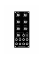
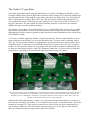
5U Oakley Modular Series
Voltage Controlled Oscillator
The 'one of three' VCO module
User Manual
V6.0.5
Tony Allgood B.Eng PGCE
Oakley Sound Systems
CARLISLE
United Kingdom
Introduction
This is the User Manual for the issue 5 and issue 6 VCO 5U module from Oakley Sound.
This document contains an overview of the operation of the unit, the history of the various board
issues, and all the calibration procedures.
For the Builder's Guide which contains information on how to construct the module from our PCB
and parts kits please visit the main project webpage at:
http://www.oakleysound.com/vco.htm
For general information regarding where to get parts and suggested part numbers please see our
useful Parts Guide at the project webpage or http://www.oakleysound.com/parts.pdf.
For general information on how to build our modules, including circuit board population, mounting
front panel components and making up board interconnects please see our generic Construction
Guide at the project webpage or http://www.oakleysound.com/construct.pdf.
The Oakley 'One of three' VCO Module
The Oakley ‘One of Three’ is a voltage controlled oscillator module that was inspired in part by the
VCO design of the later MiniMoogs. In this module I decided to create a VCO that sounded good
and performed well enough to keep up with the digital oscillators of modern day synthesisers.
The VCO features sawtooth, pulse, triangle and a low distortion sine output. The duty cycle of the
pulse output may be controlled directly by a PCB mounted pot, and also an external voltage, the
sensitivity being controlled by another PCB mounted pot. The frequency of the VCO can be
controlled by two PCB mounted pots, one for fine, the other for coarse adjustment. These four pots
are designed to be fitted to the main board, and when special pot brackets are used, the PCB can be
firmly supported to the front panel.
The output levels for the sawtooth, sine and triangle are standardised at +/-5V, ie. 10V peak to peak.
The pulse wave output is also 10V peak to peak, but the peak levels vary with pulse width. The
Oakley VCO uses an interesting technique to maintain the average voltage over one cycle to zero
volts. This new circuit essentially adds an offset to the pulse output to compensate for the non zero
average voltage for any pulse wave that isn't a square wave. Ordinarily, one would see average DC
values varying from +5V to -5V as the PW is swept from one end to the other. In the new VCO, this
average level is kept at zero. This means that for narrow pulses, you now have a wave that goes
from just below 0V [down] to just below +10V [up]. For square waves, you have the usual +5V up
and -5V down. For wide pulses, you have a wave that is just below 0V [up] and just below -10V
[down]. The reason for this is that fast pulse width modulation no longer adds thumping to the
audio output. ie. fast EG sweeps of PW will sound great.
All outputs have an output impedance of roughly 1K.
The pulse output is also switchable between ‘centre modulated’ and ‘edge modulated’ forms of
pulse width modulation. Most VCOs will only offer edge modulated, in which only one edge of the
pulse wave is affected by the pulse width pot or modulating CV. The Oakley VCO allows you to
modulate either one edge (edge) or both (centre). In fixed pulse width applications this generally
makes no audible difference. However, when used with fast moving modulating CVs the difference
in timbre is apparent.
A high impedance synchronisation input is provided to prematurely reset the VCO waveform. With
this you can force the VCO’s operating frequency to that of an external sawtooth signal, say from
another VCO module. This input is level sensitive, so hard sync is possible with inputs of about
+3V or above. Inputs below this will cause only occasional synchronisation leading to interesting
harmonic structures.
Please note; that to cause hard sync effects the master ‘sync’ signal must be a sawtooth (falling
ramp shape) waveform of 10V peak to peak. The slave VCO will not sync to a ramp waveform
which typically has a rising ramp and does not feature the fast rising edge the VCO needs to lock on
to. These ramp waveforms are, in my opinion, erroneously called sawtooth by some manufacturers.
However, a simple inverting circuit will be sufficient to turn the waveform around the right way so
it can be used as a sync master.
The VCO supports the standard 1.00V/octave exponential voltage to frequency relationship.
However, a linear control input is also provided for constant depth frequency modulation.
Temperature compensation is performed by using a matched transistor pair in the exponential
convertor, and a high quality temperature sensitive resistor.
The Oakley CV/gate Buss
You really should think about using the Oakley Buss if you have a medium sized Oakley system.
Using the Oakley Dizzy board it allows the 'keyboard control voltage' (KCV) and Gate signals to be
piped around the back of the modular’s case along with the power supply rails. Any VCO and VCF
can be connected to the Oakley Buss's KCV line, and this will save you having to patch KCV to
every module that needs it. Inserting any patch lead into the 1V/OCT socket will override the CV
bus line connection. The gate signals are treated similarly to the KCV line but for use with the
ADSRs and other envelope generator modules.
The Oakley CV/gate buss uses a common three way 0.1” Molex KK header to carry the two signal
lines around your modular. A third, as yet unused connection is also present for future expansion,
although typically this is taken to ground on the Dizzy board. More information can be found in the
Dizzy Builder's Guide.
VCO issues 4,5 and 6 support the Oakley CV/gate buss natively. Previous issues had the CV buss
being connected to the module via a wire tail attached to the 1V/octave socket’s normally closed
(NC) lug. The socket board features an optional three way header that can be fitted to allow direct
connection to the CV/gate buss on an installed Oakley Dizzy system or with our VCO Controller
module. If not required, a simple two way jumper, like those used on computer motherboards, can
be fitted to connect between pins 1 and 2. By fitting this jumper the 1V/octave socket is shorted to
ground when a jack plug is not inserted thus reducing pick up from stray signals.
There are four headers on the VCO module's socket board. Three of them will be fitted with connectors that go to
other parts of the module. The Oakley Buss is the unconnected three way header on the right. If you are not
intending to use it it should have a small two way jumper link inserted across pins 1 and 2. Pin 1 is the one
furthest to the left and nearest the other big connector.
Although the Oakley Buss header is a three way connector the actual interconnect you need to use
has only one wire fitted. The Oakley VCO is connected only to pin 1 of the Oakley Buss. This is the
connection carrying KCV. This means you need to use only a single wire that is terminated in a 3
way housing at either end. The first location of the housing, pin 1, is the only one used with the
other two locations being left empty and no other wires needed.
On no account should an interconnect with all three wires fitted be used to connect the Oakley Buss
to any module. The middle location, pin 2, is ground on the module and this should not be
connected to the Dizzy or midiDAC modules. Connecting the ground of a module to the Dizzy
ground in this way may induce earth loops and other problems.
Oakley VCO Issue Changes
For those interested the Oakley VCO has evolved slowly over the last eleven years:
Issue 1: The project started in 1999 and the VCO is based primarily on the third series Minimoog
VCO with plenty of additions. eg. in built 10V reference, sync, different exponential convertor and
summing stage, sine wave output, pulse width selection, output buffering, Omeg Eco-16 pots.
Temperature compensation was generally provided by a +3000ppm/K 900mW film resistor. This
was later upgraded to the KRL wirewound types for last ten or so boards that were sold.
Issue 2: Boards had the following features added:
Added -10V reference to go with the +10V internal reference voltage already on issue 1. This
stabilises absolute pitch drift so that supply rail potential doesn't affect the pitch of the VCO. All
pitch pots use the +/-10V references.
The range of the TUNE trimmer was reduced and this was coupled with a reduction in the quiescent
operating frequency.
Added SYNC input buffer circuit. This has the advantage of providing a high impedance input. The
old issue had a 10K input resistance which caused a slight drop in amplitude to the other (master)
VCO connected to the SYNC input. An additional benefit is that unwanted cross coupling between
two or more slave VCOs was eradicated. With the older VCOs, any two slave VCOs tended to sync
to each other as well as the master. Interesting effect though.
I swapped the positions of the power supply regulator with the CV summer circuitry. This enabled
me to move the two tuning multiturn trimmers to the edge of the board. The old issue 1 board had
these parts in the centre of the PCB, and they were impossible to trim when the board was fitted
into the Oakley Orbital monosynth. Moving the trimmers to the edge means that we can now use
side adjustable trimmers in the Orbital to facilitate easy tuning with the boards in situ. This does not
affect the modular set up in any way, in that we will continue to use top adjustable trimmers as
before. As it turns out, no issue 2 boards ever made it into the Orbital project.
The pitch spacing of the polyester capacitors was changed from 0.3” to 5mm. This was in line with
other Oakley boards.
Added separate triangle and sine wave offset trimmers. This meant that switching to centre on the
PWM source switch would not affect the mark-space ratio of the square wave output.
Issue 3: Boards had the following features added:
Sine wave purity increased.
Two high frequency tracking compensation networks instead of just one. The standard Sergio
Franco technique, used on the earlier issues, is now fixed to compensate only for the FET discharge
time. Dave Rossum's technique for compensating for the bulk emitter resistance (Rbe) of the NPN
pair is now added with variable depth controlled by the new HFT trimmer.
Constant zero average output voltage from the pulse wave. This is achieved by considerable
changes to the older simple design.
The board has four Spectrol pots instead of three Omeg ones. This makes the board less cramped
since the board is now longer. The solder pads for the jack sockets now are on standard sized solder
pads. 0.1" headers are still provided for those of you who like them, although the main reason for
keeping these is the Orbital. The new board layout required a new modular faceplate to be made for
the module.
Issue 4: Boards had the following features added:
Major mechanical changes. The module is now constructed from three PCBs and features solderless
interconnects. This facilitates easy construction. The board set can still be used with the issue 3
front panel design.
Spectrol 248 pots are now used throughout the module.
Change to the high frequency tracking (HFT) circuitry to include Rene Schmitz’s improved take on
the Rossum method of compensating for Rbe.
Change to the way the fine tune pot’s CV was handled. The single metal film 10M resistor was
replaced by a simple resistor network. 10M 1% resistors are getting hard to come by these days.
Replaced the now deleted CA3080 from the sine shaping circuitry. The new board simply uses one
half of an LM13700 device.
Easy to fit to the Oakley CV/gate buss using an optional three way header fitted to the new socket
board.
All PCBs are now RoHS compliant.
Issue 5: Boards had the following features added:
Mechanical changes due to moving to yet another pot manufacturer. Spectrol were bought out by
Vishay and Vishay put their prices up considerably on the old Spectrol ranges. This inevitably
meant that we had to look for alternatives. Although the Chinese made BI TT 260P pots fitted into
our boards we had problems with getting reliable supplies of these pots. Thus the issue 5 VCO was
our first 5U board to be revised to Alpha 16mm pots. We had been successfully using these pots on
our 3U range and our rack projects. They offered a good quality pot and at an excellent price.
The new pots have a smaller shaft and a smaller diameter mounting bush. The pot mounting holes
in the front panel have had to be reduced accordingly.
We also had to say goodbye to our trusty SSM2210P matched NPN transistor pair. Prices had been
rising steadily over the last couple of years and in late 2009 Analog Devices, the manufacturers of
the SSM line, decided to cease production. We turned to the superb THAT300. Although a quad
NPN array, and twice as big as we needed, the price is good and quality outstanding. An added
benefit of this is that the Schmitz Rbe compensation can be done within the same device as the
exponential NPN pair.
Synthesizers.com power header added to the board.
Issue 6: Boards had the following changes:
The old style 0.2” ceramic capacitors have been replaced with the newer 2.5mm type.
Added protection diodes to the THAT300 exponential converter to prevent possible long term
damage if the Linear FM input was taken very heavily negative.
Improved HFT compensation circuitry.
Moved top pot closer to the edge of the PCB so that it no longer needs a metal shim washer on the
inside of the panel.
Power supply requirements
The design requires plus and minus 15V supplies. The power supply should be adequately
regulated. The current consumption is about 30mA for each rail. Power is routed onto the PCB by a
four way 0.156” MTA156 type connector or the special five way Synthesizers.com MTA100
header.
Power connections – MOTM and Oakley
The PWR power socket is 0.156” MTA 4-way header. This system is compatible with MOTM.
Power
Pin number
+15V
Module GND
Earth/PAN
-15V
1
2
3
4
The earth/pan connection has been provided to allow the ground tags of the jack sockets to be
connected to the powers supply ground without using the module’s 0V supply. Earth loops cannot
occur through patch leads this way, although screening is maintained. Of course, this can only work
if all your modules follow this principle.
Power connections – Synthesizers.com
The PWR2 power socket is to be fitted if you are using the module with a Synthesizers.com system.
In this case the PWR header is not fitted. The PWR header is a six way 0.1” MTA, but with the pin
that is in location 2 removed. In this way location 3 is actually pin 2 on my schematic, location 4 is
actually pin 5 and so on.
Power
Location number
Schematic Pin number
+15V
Missing Pin
+5V
Module GND
-15V
Not connected
1
2
3
4
5
6
1
2
3
4
5
+5V is not used on this module, so location 3 (pin 2) is not actually connected to anything on the
PCB.
If the PWR2 header is fitted then pins 2 and 3 of PWR are linked together. This connects the panel
ground with the module ground.
Calibration
You should use a proper trimmer tool for the adjusting of all four multiturn trimmers. Vishay,
Bourns and others make trimmer adjusters for less than a pound.
Before you calibrate you should make sure that the HFT trimmer is adjusted so that the HFT
circuitry is turned off. To do this you must disconnect the module from the power supply and then
with a resistance meter measure between the top pin of R20 and pin 4 of U4. Turn the HFT trimmer
until this reading drops to zero, or near zero, ohms.
Now power up the module and make sure it has been powered up for at least twenty minutes prior
to calibration. Also, it is a good idea to have the room temperature close to what it would normally
be when playing your modular.
PSU: Adjust the trimmer PSU to give 10.00V at TP1. The voltage is measured between TP1 and a
handy ground (0V) point. For the ground point I use either the square pad on the pot board just
under the word LINK or the lower lead of the temp co resistor which is near the word R30 on the
PCB.
V/OCT: Use this to generate a perfect 1V/octave scaling. This trimmer will need to be adjusted
along with the fine and coarse pots on the front panel. You will need a digital frequency counter, or
my favourite, a guitar/chromatic tuner or tuner plug-in. Some people use another keyboard or a
calibrated VCO and listen to the beats, but that can take longer.
Plug your midi-CV convertor or 1V/oct keyboard into the 1V/octave input of the VCO. Play a
lowish note on the keyboard, then go two octaves higher. Adjust V/OCT until the interval is exactly
two octaves. I normally try to work between the two As of 220.0Hz and 880.0Hz.
However, please note we are only setting the interval and not the actual frequency. It does not have
to be a perfect A when A is being pressed on the keyboard. It could be an F or whatever. The
important thing is that we are setting the musical gap between the notes. If you do need to alter the
pitch of the VCO to help you, use the front panel controls only. Leave the TUNE trimmer until
later.
For any interval, if you find the higher note is flat, then turn the V/OCT trimmer to make it flatter
still. This actually reduces the range between the two notes. Conversely, if you find your interval is
greater than an octave, turn the trimmer to make the top note even higher. I always adjust V/OCT
on the high note of any interval, and only adjust the front panel Tune pot on the lower.
This will probably require some patience and plenty of twiddling of the front panel controls as well.
But you will get there. Once you get the hang of it, its easy. I can do it in about one minute but I’ve
had a lot of practice.
Now leave it on for a further 20 minutes, and then check the scaling again. Adjust if necessary.
HFT: This is the high frequency tracking trimmer and it compensates for the slight flattening of
pitch at when running the VCO at high frequencies. If you don't go above 4kHz that often there is a
good chance you won't even have to touch this one.
If you only have a small keyboard use the keyboard's octave transpose setting and the module's
coarse tune control to get the VCO playing a really high note. For setting the HFT I work between
the two As of 7040Hz and 14,080Hz. However, you can ignore the actual pitch, it's the interval we
are wanting to get right. Once you have set up the perfect octave at these frequencies, then check
down at the lower end that everything is still responding to 1V/octave.
Remember, if you have skimped on the V/OCT trimming, no amount of tweaking of the HFT will
get it to play in tune.
If your digital tuner will not track at very high frequencies then a good trick is to use an octave
divider plug in or module. For each octave division you reduce the frequency by two. This divided
output should be low enough for your tuner to work properly.
TUNE: This sets the range over which your VCO acts.
Set the Coarse pot to its minimum setting and set the Fine pot to its middle position. Play the lowest
note on your keyboard. Now adjust the TUNE trimmer until the note that you can hear is equivalent
to your lowest note minus three semitones or so. That is if your bottom note is a C, then adjust
TUNE so that you get a A.
In normal operation the Coarse Tune pot would be just off its minimum value to set the correct
note. You may want to compare it to another keyboard module, to make sure that you have set it to
the right octave.
As far as I am aware there is no standard amongst modular systems that defines what pitch
corresponds to what CV input. However, I choose to make my VCOs produce middle C (C4) at
their typical settings when the 1V/octave input is at 5.00V. Thus, I would expect the VCO to be
producing 261.6Hz when its KeyCV input is 5V, the coarse tune pot is set to slightly above the
minimum and the fine tune pot in the middle..
SHP-T: Play an A an octave above middle C. Adjust SHP-T so that the triangle output sounds
smooth. You will know when it is right. If you have a scope, adjust SHP-T so that the sharp steps
disappear from the output.
SYM-T: Set the PWM TYPE switch to EDGE. Listen to the pulse output at any frequency that’s
comfortable to listen to. Now, turn the PULSE WIDTH pot to give you a square wave. This will be
somewhere near the middle of its travel. A square wave sounds hollower and less buzzy than the
pulse wave, so it should be easy to find. Now set the PWM type switch to CENTRE. It’ll probably
change the tone of the output signal. Adjust the SYM-T trimmer so that you can again hear the
square wave. Flick between the two modes to confirm that you have a square wave in each switch
position.
SYM-S and SHP-S: Plug the sine output into an amplifier and use your ears for this one. Set the
VCO to make a lowish note, around 200Hz will do. Adjust SHAPE until the sine output sounds
pure. Its shouldn’t be too buzzy or too hollow. Then go back and adjust the SYM-S trimmer to get it
really pure. You may need to bounce back and forth between the two trimmers until you get a good
sound. Its not essential to get this right, just set it so you get a nice sounding output. It’s easier to do
than to explain.
Now you have set up your VCO, and you are ready to go.
Final Comments
I hope you enjoy using the Oakley VCO.
If you have any problems with the module, an excellent source of support is the Oakley Sound
Forum at Muffwiggler.com. Paul Darlow and I are on this group, as well as many other users and
builders of Oakley modules.
If you have a comment about this user manual, or have a found a mistake in it, then please do let me
know.
Last but not least, can I say a big thank you to all of you who helped and inspired me. Thanks
especially to all those nice people on the Synth-diy and Analogue Heaven mailing lists and those at
Muffwiggler.com.
Tony Allgood at Oakley Sound
Cumbria, UK
© January 2011 – updated April 2012
No part of this document may be copied by whatever means without my permission.


![Manual condicionador de sinal SD20 [PTBR]](http://vs1.manualzilla.com/store/data/006085115_1-891da68fb4d8bbd4bc5f0d8350060514-150x150.png)

