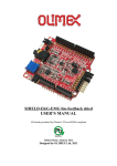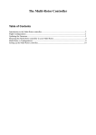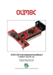
1
OLIMEXINO-328
an Arduino-like development board
USER’S MANUAL
Manual revision B, November 2013
Designed by OLIMEX Ltd, 2011
All boards produced by Olimex LTD are ROHS compliant
OLIMEX© 2013
OLIMEXINO-328 user's manual
DISCLAIMER
© 2013 Olimex Ltd. Olimex®, logo and combinations thereof, are registered trademarks of Olimex Ltd. Other product
names may be trademarks of others and the rights belong to their respective owners.
The information in this document is provided in connection with Olimex products. No license, express or implied
or otherwise, to any intellectual property right is granted by this document or in connection with the sale of
Olimex products.
This work is licensed under the Creative Commons Attribution-ShareAlike 3.0 Unported License. To view a copy of
this license, visit http://www.creativecommons.org/licenses/by-sa/3.0/.
This hardware design by Olimex LTD is licensed under a Creative Commons Attribution-ShareAlike 3.0 Unported
License.
The software is released under GPL.
It is possible that the pictures in this manual differ from the latest revision of the board.
The product described in this document is subject to continuous development and improvements. All particulars of the
product and its use contained in this document are given by OLIMEX in good faith. However all warranties implied or
expressed including but not limited to implied warranties of merchantability or fitness for purpose are excluded. This
document is intended only to assist the reader in the use of the product. OLIMEX Ltd. shall not be liable for any loss or
damage arising from the use of any information in this document or any error or omission in such information or any
incorrect use of the product.
This evaluation board/kit is intended for use for engineering development, demonstration, or evaluation purposes only
and is not considered by OLIMEX to be a finished end-product fit for general consumer use. Persons handling the
product must have electronics training and observe good engineering practice standards. As such, the goods being
provided are not intended to be complete in terms of required design-, marketing-, and/or manufacturing-related
protective considerations, including product safety and environmental measures typically found in end products that
incorporate such semiconductor components or circuit boards.
Olimex currently deals with a variety of customers for products, and therefore our arrangement with the user is not
exclusive. Olimex assumes no liability for applications assistance, customer product design, software performance, or
infringement of patents or services described herein.
THERE IS NO WARRANTY FOR THE DESIGN MATERIALS AND THE COMPONENTS
USED TO CREATE OLIMEXINO-328. THEY ARE CONSIDERED SUITABLE ONLY FOR
OLIMEXINO-328.
Page 2 of 23
OLIMEX© 2013
OLIMEXINO-328 user's manual
Table of Contents
DISCLAIMER............................................................................................................. 2
CHAPTER 1 - OVERVIEW.......................................................................................5
1. Introduction to the chapter.......................................................................................................5
1.1 Introduction to Arduino.......................................................................................................... 5
1.2 Improvements over the original Arduino design.................................................................. 5
1.3 Target market and purpose of the board...............................................................................7
1.5 Document organization........................................................................................................... 7
CHAPTER 2 - SETTING UP THE OLIMEXINO-328........................................... 8
2. Introduction to the chapter.......................................................................................................8
2.1 Electrostatic warning...............................................................................................................8
2.2 Requirements........................................................................................................................... 8
2.3 Connecting to Arduino IDE....................................................................................................9
CHAPTER 3 - OLIMEXINO-328 BOARD DESCRIPTION................................10
3. Introduction to the chapter.....................................................................................................10
3.1 Layout (top view)...................................................................................................................10
3.2 Layout (bottom view).............................................................................................................11
CHAPTER 4 - CONTROL CIRCUITY.................................................................. 12
4. Introduction to the chapter.....................................................................................................12
4.1 Reset........................................................................................................................................12
4.2 Clocks......................................................................................................................................12
4.3 Power supply circuit.............................................................................................................. 12
CHAPTER 5 - INTERFACES AND HARDWARE................................................13
5. Introduction to the chapter.....................................................................................................13
5.1 UEXT connector.....................................................................................................................13
5.2 PWR_J connector.................................................................................................................. 13
5.3 Arduino shield platform........................................................................................................ 14
5.3.1 CON1 – POWER............................................................................................................14
5.3.2 CON2 – ANALOG......................................................................................................... 14
5.3.3 CON3 – DIGITAL..........................................................................................................14
5.3.4 CON4 – DIGITAL:........................................................................................................ 15
5.4 mini USB connector...............................................................................................................15
5.5 ICSP pads................................................................................................................................15
5.6 Jumper description................................................................................................................16
5.6.1 USB_RST jumper...........................................................................................................16
5.6.2 LED1_E jumper ............................................................................................................16
5.6.2 D7/D10 jumper ..............................................................................................................16
5.7 LEDs and buttons:.................................................................................................................17
CHAPTER 6 - SCHEMATICS.................................................................................18
Page 3 of 23
OLIMEX© 2013
OLIMEXINO-328 user's manual
6. Introduction to the chapter.....................................................................................................18
6.1 Eagle schematics.................................................................................................................... 18
6.2 Physical dimensions...............................................................................................................20
CHAPTER 7 - REVISION HISTORY AND SUPPORT....................................... 21
7. Introduction to the chapter.....................................................................................................21
7.1 Document revision................................................................................................................. 21
7.2 Board revision........................................................................................................................ 21
7.3 Useful web links and purchase codes...................................................................................22
7.4 FAQ......................................................................................................................................... 22
7.5 Product support..................................................................................................................... 23
Page 4 of 23
OLIMEX© 2013
OLIMEXINO-328 user's manual
CHAPTER 1 - OVERVIEW
1. Introduction to the chapter
Thank you for choosing the OLIMEXINO-328 board from Olimex! This document provides a
user’s guide for the Olimex Arudino-like OLIMEXINO-328. As an overview, this chapter gives the
introduction to Arduino, the scope of this document and lists the features of the board. The
document’s organization is then detailed.
1.1 Introduction to Arduino
Arduino is an open-source electronics prototyping platform, designed to make the process of using
electronics in multidisciplinary projects more accessible. The hardware consists of a simple open
design for the Arduino board with an Atmel AVR processor and on-board I/O support. The software
consists of a standard programming language and the boot loader that runs on the board.
Arduino hardware is programmed using a Wiring-based language (syntax + libraries), similar to C+
+ with some simplifications and modifications, and a processing-based IDE.
The project began in Ivrea, Italy in 2005 to make a device for controlling student-built interaction
design projects less expensively than other prototyping systems available at the time. As of
February 2010 more than 120,000 Arduino boards had been shipped. Founders Massimo Banzi and
David Cuartielles named the project after Arduino, a local bar. The name is an Italian masculine
first name, meaning "strong friend". The English pronunciation is "Hardwin", a namesake of
Arduino of Ivrea.
More information can be found at the creators web page http://arduino.cc/ and in the Arduino Wiki
http://en.wikipedia.org/wiki/Arduino. To make the story short - Arduino is easy for the beginners
with minimal Electronics knowledge, while not restricting the professionals, as they can program it
in C++ or a mix of Arduino/C++ language.
There are thousands of projects which make the startup easy as there is almost no
field Arduino enthusiasts have not explored already.
1.2 Improvements over the original Arduino design
We entered the Arduino field 5 years after the design was introduced, allowing us to see and skip
most of the errors the Arduino inventors made. We were able to read feedback from current
customers and to implement what they wanted to see in the original Arduino.
There are a number of improvements over the original Arduino design that we have
implemented in OLIMEXINO-328:
1. We allowed the board to work at different frequencies with easy exchange of the quartz crystal.
2. The original Arduino used a linear power supply. This limited the input voltage range. We
designed a switching power supply to accept input voltages from 9 to 30V DC, making it possible
Page 5 of 23
OLIMEX© 2013
OLIMEXINO-328 user's manual
to use virtually any power supply adapter on the market, including applications with the standard
24VDC industrial power supply.
3. We carefully selected all components to work reliably over the industrial temperature range
-25+85C so the board can be used in industrial applications (the original design was suitable for the
commercial 0-70C operating temperature).
4. The original Arduino design was not good for portable applications as it dissipated too much
power in the linear voltage regulators. We chose ULTRA LOW POWER voltage regulators with
consumption of only few microamps to enable handheld and battery powered applications.
5. We added a Li-Ion rechargeable battery power supply option with a BUILT-IN onboard charger,
so when a battery is attached it is automatically kept charged . When the other power source (USB
or external adapter) is removed it will AUTOMATICALLY power the board - no jumpers, no
switches!
6. Our design can work both on 3.3V and on 5V, switch-selectable.
7. Our boards included the UEXT connector, allowing many existing modules like RF, ZIGBEE,
GSM, and GPS to be connected. It also saves soldering to interface I2C, UART and/or SPI.
8. Our design allows a Real Time Clock (RTC).
9. We made our design noise immune in the RESET circuit. There are a number of threads on the
Arduino forum for problems with the RESET when the board works with motors, since Atmel
recommendations were omitted in the original design. We fixed this.
10. We used a separate voltage regulator for the Analog part, allowing the ADC to be read correctly
without digital noise pickup.
11. We made provision for the optional ARef precision voltage source, for users who need higher
precision and temperature stability in Analog readings.
12. We placed the LEDs and the BUTTONs on the edge of the board for easy access even if the
boards have shields on them.
13. All components were placed LOWER than the connectors, so the shields do not interfere with
them.
14. We used a mini USB connector which is common and used in most cell phones, so you do not
have to buy other cables.
15. The original design did not space the connectors at 0.1", making perfboard use impossible. For
compatibility, we used the same spacing but we added footprints next to the connectors on 0.1"
which customers can use with perforated boards.
16. All signals on the connectors are printed on top and on bottom of the board, so when you check
with a probe you know exactly which point you are measuring.
Page 6 of 23
OLIMEX© 2013
OLIMEXINO-328 user's manual
17. We added 4 mounting holes making board attachment easier.
1.3 Target market and purpose of the board
The board is aimed at beginners due to the fact it might be programmed without the need of thirdparty tools and the big Arduino community. It is also suitable for professionals due to the industrial
range of operation, small form factor and wide power supply choice. The board is suitable for handheld applications.
1.4 Hardware revision of the board used in the manual
Revision B and revision C boards and resources were used while writing this document. It is
possible that all revisions used to create the document are outdated so it is recommended to
download the latest sources from the web-page of OLIMEXINO-328 at the official
www.olimex.com web-site.
1.5 Document organization
Each section in this document covers a separate topic, organized as follow:
Chapter 1 is an overview of the board usage and features
Chapter 2 provides a guide for setting the board
Chapter 3 contains the general board diagram and layout
Chapter 4 mentions the control circuitry used in OLIMEXINO-328
Chapter 5 is an explanation of the connectors, the LEDs and the jumpers position
Chapter 6 contains the general board diagram and layout
Chapter 7 contains the revision history, useful links and support information
Page 7 of 23
OLIMEX© 2013
OLIMEXINO-328 user's manual
CHAPTER 2 - SETTING UP THE OLIMEXINO-328
2. Introduction to the chapter
This section helps you set up the OLIMEXINO-328 development board for the first time.
Please consider first the electrostatic warning to avoid damaging the board, then discover the
hardware and software required to operate the board.
The procedure to power up the board is given, and a description of the default board behavior is
detailed.
2.1 Electrostatic warning
The OLIMEXINO-328 board is shipped in protective anti-static packaging. The board must not be
subjected to high electrostatic potentials. General practice for working with static sensitive devices
should be applied when working with this board.
2.2 Requirements
In order to set up the OLIMEXINO-328 optimally, you might need to update your set of hardware
and/or software tools. The major needed components are listed below.
Hardware tools:
- USB type A to USB mini cable
- Personal computer with USB type A port
Software tools:
- any official Arduino IDE
You would need additional hardware and software if you want to use OLIMEXINO-328 as a
general-purpose Atmel AVR board (or you want to reprogram the bootloader, required for Arduino
IDE communication).
You would need to a have a working combination of a programmer tool and a software
development environment. You would also need a 6-pin header or jumper wires to establish proper
hardware connection between the programmer tool and the board.
Currently OLIMEX sells a couple of ATmega328-compatible programmers that would also work
with the most common software environments (AVR Studio 4 and 5; Atmel Studio 6; AVRdude –
the built-in Arduino programmer). These programmers are: AVR-ISP500 and AVR-ISP-MK2.
Page 8 of 23
OLIMEX© 2013
OLIMEXINO-328 user's manual
2.3 Connecting to Arduino IDE
The latest Arduino IDE might be downloaded from the official Arduino web-site: http://arduino.cc.
After you have downloaded and installed (or extracted) the environment you should connect the
OLIMEXINO-328 to the computer via an USB type A to USB mini cable.
The first time you connect the board you would be asked for drivers. You can find the drivers
needed for OLIMEXINO-328 in the install folders of the Arduino IDE (usually in folder “drivers”).
After the drivers are successfully installed you should run the Arduino IDE.
In “Tools->Board” you should select “Arduino Duemilanove w/ ATmega328”.
That is all. Now you can load any built-in example or you can refer to the number of demo
examples in the “SOFTWARE” section of the OLIMEXINO-328's web-page:
https://www.olimex.com/Products/Duino/AVR/OLIMEXINO-328/
For more detailed instructions and Linux installation please check the following document:
https://www.olimex.com/Products/Duino/AVR/OLIMEXINO-328/resources/Install_OLIMEXINO328.pdf
Page 9 of 23
OLIMEX© 2013
OLIMEXINO-328 user's manual
CHAPTER 3 - OLIMEXINO-328 BOARD DESCRIPTION
3. Introduction to the chapter
Here you get acquainted with the main parts of the board. Note the names used on the board differ
from the names used to describe them. For the actual names, please, check the OLIMEXINO-328
itself.
3.1 Layout (top view)
Page 10 of 23
OLIMEX© 2013
OLIMEXINO-328 user's manual
3.2 Layout (bottom view)
Page 11 of 23
OLIMEX© 2013
OLIMEXINO-328 user's manual
CHAPTER 4 - CONTROL CIRCUITY
4. Introduction to the chapter
Here you can find information about reset circuit and quartz crystals locations, the power supply
circuit is discussed.
4.1 Reset
OLIMEXINO-328 reset circuit includes R12 (4.7kΩ), R13 (330Ω), SD5 (1N4148), C7 (4.7nF),
C8(100nF), jumper USB_RST, ATmega328P pin29 (PC6/3RESET/PCINT14) and RST button.
4.2 Clocks
Quartz crystal Q1 16 MHz is connected to ATmega328P pin 7 (XTAL1) and pin 8 (XTAL2). Note
that the crystal is on socket and can be changed to any value.
4.3 Power supply circuit
OLIMEXINO-328 can take power supply from:
- external power supply (9-30) VDC.
- +5V from USB
- 3.7V Li-ion battery
The programmed board power consumption is about 20mA with all peripherals enabled.
Page 12 of 23
OLIMEX© 2013
OLIMEXINO-328 user's manual
CHAPTER 5 - INTERFACES AND HARDWARE
5. Introduction to the chapter
In this chapter are presented the interfaces found on the programmed that can be found on the
board. Jumpers functions are described.
5.1 UEXT connector
The UEXT is used to connect additional extension modules to the OLIMEXINO-328. Most Olimex
extensions (named MOD-XXXX) can be plugged directly to this connector. If you wish to add
additional extras to your board this is the right interface. Of course, using jumper wires you might
connect any other board that uses I2C, SPI or UART interface without the need of soldering.
More information about the UEXT might be found here:
https://www.olimex.com/Products/Modules/UEXT/
Pin #
1
2
3
4
5
6
7
8
9
10
Signal name
VCC
GND
D1(TXD)
D0(RXD)
A5(SCL)
A4(SDA)
D12(MISO)
D11(MOSI)
D13(SCK/LED1)
UEXT_#CS
5.2 PWR_J connector
The power jack used is the typical 2.5mm one used by Olimex in most of our products. You should
provide between 6 and 16 volts @ 1.5A maximum to the board.
Note that we also sell a couple of compatible 12V capable power supplies suitable for European
customers. These might be found here: https://www.olimex.com/Products/Power/.
Pin #
1
2
Signal name
Power Input
GND
Page 13 of 23
OLIMEX© 2013
OLIMEXINO-328 user's manual
5.3 Arduino shield platform
These four connectors are usually used when you want to mount extension shield on the
OLIMEXINO-328. The shield connector layout follows the original Arduino layout and spacing
BUT we have also provided set of metalized holes that improve the layout by keeping 0.1'' step
between connectors. The extra holes might be used when the original connector get clunky of wires.
They can be used for placing measuring tools.
Olimex has a number of shields available. They might be found here:
https://www.olimex.com/Products/Duino/Shields/
5.3.1 CON1 – POWER
Pin #
1
2
3
4
5
6
Signal name
RESET
+3.3V
+5V
GND
GND
VIN
5.3.2 CON2 – ANALOG
Pin #
1
2
3
4
5
6
Signal name
A0
A1
A2
A3
A4(SDA)
A5(SCL)
5.3.3 CON3 – DIGITAL
Pin #
1
2
3
4
5
6
7
8
Signal name
D0(RXD)
D1(TXD)
D2(BUT)
D3
D4
D5
D6
D7
Note: There is a capacitor C12 connected to D2 and in parallel to BUT (for filtering bounces of the
BUT) but it can cause interference (and unwanted filtering of signals) if you want to connect for
instance RF module to D2, remove C12.
Page 14 of 23
OLIMEX© 2013
OLIMEXINO-328 user's manual
5.3.4 CON4 – DIGITAL:
Note that the additional pads near the CON4 seems slightly off due to the improvement of the shield
design we have made. Consider this alignment when referring to the white print on the board.
Pin #
1
2
3
4
5
6
7
8
Signal name
D8
D9
D10(#SS)
D11(MOSI)
D12(MISO)
D13(SCK/LED1)
GND
AREF
5.4 LIPO_BAT connector
The LIPO_BAT connector comes handy when you want to use the OLIMEXINO-328 as a standalone device.
Pin #
1
2
Signal name
VBAT
GND
Olimex LTD has a number of batteries with the proper connector. They might be found here:
https://www.olimex.com/Products/Power/
5.4 mini USB connector
Pin #
1
2
3
4
5
Signal name
+5V_VBUS (VCCINT)
USBDM
USBDP
Not connected
GND
5.5 ICSP pads
Pin #
1
2
3
4
5
6
Signal name
D12(MISO)
VCC
D13(SCK/LED1)
D11(MOSI)
RESET
GND
Note, that there is no plastic component mounted for this connector. You would either need own
Page 15 of 23
OLIMEX© 2013
OLIMEXINO-328 user's manual
connector or jumper wires to be able to connect your AVR programmer tool.
Please make sure you are not trying to use TPI or PDI interface with the ICSP pads.
If your programmer has only 10 pin ICSP cable you would need to use jumper wires or adapter to
be able to connect to the 6 pin interface.
5.6 Jumper description
The pictures below show the default jumper position. Note that the board has only SMT jumpers
which require soldering to close the jumper; and melting the solder plus cutting between the pads to
disconnect the jumper.
5.6.1 USB_RST jumper
When closed USB_RST jumper enables USB auto-reset function. After reset the bootloader is
started and loads the program into the Flash.
Default state is closed.
5.6.2 LED1_E jumper
When closed LED1_E, connects LED1 to D13(SCK) line.
Default state is closed.
5.6.2 D7/D10 jumper
When D7/D10 jumper is closed in position D7 – UEXT pin 10 (UEXT_CS) is connected to
Atmega328P pin 11 (PD7) – signal D7, when this jumper is closed in position D10 - UEXT pin 10
(UEXT_CS) is connected to Atmega328P pin 14 (PB2/#SS) – signal D10(3SS).
Default state is closed in position D7.
5.7 LEDs and buttons:
Status LED with name LED1 (green) connected via jumper LED1_E to ATmega328P pin 17
Page 16 of 23
OLIMEX© 2013
OLIMEXINO-328 user's manual
(SCK/PCINT5/PB5) – signal D13(SCK/LED1).
Status LED with name LED2 (yellow) connected to ATmega328P pin 13 (PCINT1/OC1A/PB1) –
signal D9(LED2).
Status LED with name TX (red) indicates that there is transfer in the FTDI.
Status LED with name RX (green) indicates that there is transfer in the FTDI.
Power-on LED (red) with name PWR – this LED shows that the board is power supplied.
User button with name BUT connected to ATmega328P pin 32 (INT0/PCINT18/PD2) – signal
D2(BUT).
User button with name RST connected to ATmega328P pin 29 (PC6/#RESET).
Switch with name SW(3.3V/5V) – selects between 3.3V and 5V power supply of the board.
Page 17 of 23
OLIMEX© 2013
OLIMEXINO-328 user's manual
CHAPTER 6 - SCHEMATICS
6. Introduction to the chapter
In this chapter is located information about the schematics describing logically and physically
OLIMEXINO-328.
6.1 Eagle schematics
Stand-alone search-able schematic in PDF format might be found at the web page of OLIMEXINO328.
The schematic is also shown on the next page for quicker reference.
We mostly use Eagle by Cad Soft 4.16r2 for designing. However, the files should be compatible
with the latest Eagle available. Cad Soft offers a trial version of their software that allows you to
inspect schematics and board files (without being able to modify them).
This work is licensed under the Creative Commons Attribution-ShareAlike 3.0 Unported License.
To view a copy of this license, visit http://creativecommons.org/licenses/by-sa/3.0/.
Page 18 of 23
OLIMEX© 2013
OLIMEXINO-328 user's manual
Page 19 of 23
OLIMEX© 2013
OLIMEXINO-328 user's manual
6.2 Physical dimensions
Note that all dimensions are in inches.
Page 20 of 23
OLIMEX© 2013
OLIMEXINO-328 user's manual
CHAPTER 7 - REVISION HISTORY AND SUPPORT
7. Introduction to the chapter
In this chapter you will find the current and the previous version of the document you are reading.
Also the web-page for your device is listed. Be sure to check it after a purchase for the latest
available updates and examples.
7.1 Document revision
Revision, date
Changes
Modified page
A, 20.08.11
Initial manual release
All
B, 14.11.13
Major document changes
All
7.2 Board revision
Remember to check the schematics and the board design files to compare the differences.
Revision
B
C
Notable changes
Initial release of the board
1. Changed 0805 LEDs to 0603 LEDs and resistors to 2K to
reduce overall current consumption
2. Added new label “Made in Bulgaria” in the board file
3. Added jumpers that help disconnecting pull-up resistors
of signals of the Arduino shield platform
4. Added new label “Designed by Olimex_LTD” in the schematic
5. Adjusted resistors 10uF/6.3V(0805) to 10uF/10V(0603)
Page 21 of 23
OLIMEX© 2013
OLIMEXINO-328 user's manual
7.3 Useful web links and purchase codes
The web page you can visit for more info on your device is
https://www.olimex.com/Products/Duino/AVR/OLIMEXINO-328/.
For more info on the original Arduino design please visit:
http://arduino.cc/en/Main/arduinoBoardDuemilanove.
ORDER CODES:
OLIMEXINO-328 - assembled and tested Arduino-like board
AVR-ISP500 – assembled and tested AVR-ISP compatible programmer
AVR-ISP-MK2 – assembled and tested AVR-ISP compatible programmer
How to purchase Olimex products?
You can order from our web-shop or from any of our distributors. The list of official Olimex
distributors might be found at: https://www.olimex.com/Distributors/.
Please check https://www.olimex.com/ for more info.
7.4 FAQ
Q1: I installed the OLIMEXINO-328 drivers. The board shows in “Windows Device
Manager” correctly. Yet, the board cannot be programmed in Arduino IDE?
A1. Try installing older FTDI drivers. FTDI drivers 2.08.14 or earlier should fix the issue. The
problem with the FTDI drivers is described in this forum post:
https://www.olimex.com/forum/index.php?topic=2031.0.
Q2: I have OLIMEXINO-328 and Olimex AVR-ISP-MK2. The drivers seem correct, yet I'm
unable to program the board. What might be causing the problem?
A2: Very often people try to use the PDI or TPI interface of AVR-ISP-MK2 for the ICSP slot of
OLIMEXINO-328. Please, use jumper wires to transform the 10-pin ICSP of the AVR-ISP-MK2 to
6-pin ICSP connector of the OLIMEXINO-328.
Page 22 of 23
OLIMEX© 2013
OLIMEXINO-328 user's manual
7.5 Product support
For product support, hardware information and error reports mail to: [email protected]. All
document or hardware feedback is welcome. Note that we are primarily a hardware company and
our software support is limited. Please consider reading the paragraph below about the warranty of
Olimex products.
All goods are checked before they are sent out. In the unlikely event that goods are faulty,
they must be returned, to OLIMEX at the address listed on your order invoice.
OLIMEX will not accept goods that have clearly been used more than the amount needed to
evaluate their functionality.
If the goods are found to be in working condition, and the lack of functionality is a result of
lack of knowledge on the customers part, no refund will be made, but the goods will be returned
to the user at their expense.
All returns must be authorized by an RMA Number. Email [email protected] for authorization
number before shipping back any merchandise. Please include your name, phone number and order
number in your email request.
Returns for any unaffected development board, programmer, tools, and cables permitted within 7
days from the date of receipt of merchandise. After such time, all sales are considered final.
Returns of incorrect ordered items are allowed subject to a 10% restocking fee. What is
unaffected? If you hooked it to power, you affected it. To be clear, this includes items that
have been soldered to, or have had their firmware changed. Because of the nature of the
products we deal with (prototyping electronic tools) we cannot allow returns of items that have
been programmed, powered up, or otherwise changed post shipment from our warehouse.
All returned merchandise must be in its original mint and clean condition. Returns on damaged,
scratched, programmed, burnt, or otherwise 'played with' merchandise will not be accepted.
All returns must include all the factory accessories which come with the item. This includes
any In-Circuit-Serial-Programming cables, anti-static packing, boxes, etc.
With your return, enclose your PO#. Also include a brief letter of explanation of why the
merchandise is being returned and state your request for either a refund or an exchange.
Include the authorization number on this letter, and on the outside of the shipping box.
Please note: It is your responsibility to ensure that returned goods reach us. Please use a
reliable form of shipping. If we do not receive your package we will not be held liable.
Shipping and handling charges are not refundable. We are not responsible for any shipping
charges of merchandise being returned to us or returning working items to you.
The full text might be found at https://www.olimex.com/wiki/GTC#Warranty for future reference.
Page 23 of 23