1
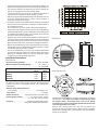
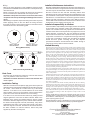
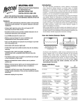
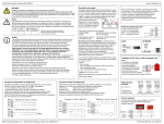
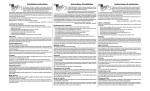
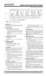
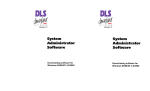
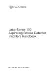
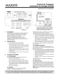
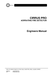
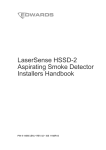
MN220 Series
How the Smoke Detector Works
2-Wire Smoke Detectors
INSTRUCTIONS FOR
INSTALLATION AND USE
READ THIS INSTRUCTION SHEET THOROUGHLY BEFORE
INSTALLING AND USING YOUR MERIDIAN SMOKE DETECTOR
Features
• Advanced 90° photoelectric detection pattern and specially
designed smoke chamber∗ for superior detection and dust
resistance
• Unique high signal-to-noise ratio and superior RFI immunity
to prevent false alarms
• Excellent smoke access provides reliable detection for all
smoke flow directions and velocities
• Solid-state LED red Indicator Light
• Optional auxiliary relay Form C
• 57°C (135°F) fixed temperature heat sensor option
• Magnet-activated sensitivity test switch
• Attractive styling for any decor
• ULC listed S529
∗ Protected under Canadian patent No. 1452296. Other patents pending.
Models
MN220
MN220T
MN220R
MN220RT
As shown in the illustration, a light source is directed across the
smoke chamber and is not normally reflected into the sensing
element. When smoke enters the chamber, the light beam is
scattered by the smoke and is reflected into the sensor. When
enough light is detected by the sensor, an alarm is activated. On
alarm, the Alarm Indicator Light will come ON and the Detector will
send an alarm signal to the control panel. The Auxiliary Relay, if
equipped, is also activated on alarm. When the smoke clears
from the chamber, the detector will remain latched in the alarm
state until reset by turning off the power supply from the
control panel. Units with the temperature sensor (T) option
will activate its alarm indicator light and auxiliary relay and
initiate an alarm at the control panel also. When the high heat
condition returns to normal, the detector will remain latched in
the alarm state until reset from the control panel. Resetting is
achieved by 2 seconds of power down.
Alarm Indications
2-Wire Detector
2-Wire Detector and Fixed Temp (57oC) Sensor
2-Wire Detector and Auxiliary Form “C” Relay
2-Wire Detector and Auxiliary Form “C” Relay and Fixed
Temp (57oC) Sensor
Introduction
The DSC Meridian MN220 Series smoke detectors are two-wire
smoke detectors intended for open area protection. They are suited
for commercial, institutional and residential fire alarm systems.
The DSC Meridian photoelectric smoke detector incorporates
many advanced design features to provide years of reliable
operation. It is important to follow the Installation and operation
instructions on this sheet to ensure that the unit will function
properly — even the best designed smoke detector will be rendered
useless if it is not connected or located properly.
It is very important that you understand how to test and maintain
your system. Refer to the Instruction or User Manual for your
alarm system, and familiarise yourself with how the fire alarm
functions of your system operate. Be sure to test your system
regularly following the test procedures described in your manual.
If you should ever have problems operating or testing your
system, and especially if there are problems with the fire alarm
functions, contact your smoke detector installer or dealer
immediately for service.
While smoke detectors and alarm systems are designed to warn
you of potentially dangerous situations, no system can prevent
emergencies. An alarm system is not a substitute for life and
property insurance; you should always maintain appropriate
insurance coverage.
Condition
No smoke or heat
Alarm LED
Pulse every
40 s
Smoke or heat
Aux Relay
Deactivated
ON steady
Activated
Sensitivity test
functioning normally
ON
Steady
Activated
Sensitivity test
insufficient sensitivity
Pulse every
40 s
Deactivated
No smoke or heat
but latched in alarm
ON
steady
Activated
Limitations of Smoke Detectors
While the Meridian smoke detector has been designed for reliability,
it is important to know that all smoke detectors have limitations.
• Smoke detectors will not work without power. Devices powered
from a control panel will not function if the control panel’s AC and
battery backup power supplies both fail.
• Smoke detectors can only generate an alarm when smoke gets
inside the smoke chamber; anything that prevents smoke from
entering the smoke chamber may prevent or delay an alarm.
Refer to the ‘Guidelines for Locating Smoke Detectors’ on this
Instruction Sheet; it is important that smoke detectors be located
on at least every floor of the premises, preferably in every room.
It is also important to avoid obstructions, such as closed doors,
that may prevent smoke from reaching the unit. A smoke detector
will not detect a fire in the walls, in the chimney or on the roof of
a building until smoke enters the smoke chamber.
• Smoke detectors have certain obvious limitations: they may not
provide protection for someone smoking in bed, for children
playing with matches, or for sudden and violent explosions. A
smoke detector is a single part of overall fire safety precautions;
the smoke detector should never be seen as a substitute for a
complete fire safety program.
Guidelines for Locating Smoke Detectors
On smooth ceilings, detectors may be spaced 9.1m (30 feet)
apart as a guide. Other spacings may be required depending
on ceiling height, air movement, the presence of joists,
uninsulated ceilings, etc. Consult CAN/ULC-S553-M86 or other
appropriate national standards for installation
recommendations.
Do not locate smoke detectors at the top of peaked or gabled
ceilings; the dead air space in these locations may prevent the unit
from detecting smoke.
Avoid areas with turbulent air flow, such as near doors, fans or
windows. Rapid air movement around the detector may prevent
smoke from entering the unit.
Do not locate detectors in areas of high humidity.
Do not locate detectors in areas where the temperature rises
above 38oC (100oF) or falls below 5oC (41oF).
If the smoke detector does not function properly, call your smoke
detector installer or dealer for service.
Smoke sensitivity may be measured in a correlated CAN/ULC S529M87 smoke box. DSC will conduct this test for a nominal charge. If a
returned unit is found outside of its marked sensitivity range, DSC will
clean and restore the unit’s sensitivity to its marked range.
Smoke sensitivity of installed detectors can be measured without
removal with the Gemini Model 501 Aerosol Smoke Detector Analyzer.
Follow the instructions supplied with the instrument. Start with the
sensitivity corresponding to the lowest marked detector sensitivity; no
alarm should be indicated. Reset with the highest sensitivity setting; an
alarm should then be indicated. These results indicate that the unit is
within its marked sensitivity range. Other settings can be tried to bracket
the detector’s sensitivity to a narrower sensitivity range, such as may be
important during annual tests to quantify any change over time.
Owner’s Maintenance Instructions
The Meridian smoke detector is designed to require a minimum of
maintenance. If the case becomes dusty, wipe the case gently
with a soft dry cloth. If the case is greasy, wipe the case gently with
a soft cloth slightly dampened with soapy water.
Never disassemble the smoke detector; there are no user
serviceable parts inside the unit. Never paint the unit, as paint
may prevent smoke from entering the unit. If you are planning
renovations or repainting, contact your Installer and ask that
the unit be temporarily removed until work is complete.
If the unit is located in an area where it is exposed to high levels of
dust or insects and is found to cause false alarms, it may require
service; contact your smoke detector installer or dealer.
Fire Safety In The Home
Most fires occur in the home, and to minimize this danger, it is
recommended that a household fire safety audit be conducted and
a family escape plan be developed.
Household Fire Safety Audit
Testing Your Smoke Detector
Never use burning or
smouldering materials
to test a smoke
detector. Also, do not
use high pressure
aerosols to test smoke
detectors. The use of
burning materials or
high pressure aerosols
can give misleading
and
meaningless
results.
Test the detector for minimum sensitivity by activating the test
feature. To test the unit, hold the test magnet against the case as
shown below. The alarm indicator light will come ON, the auxiliary
relay (if equipped) will be activated, and the alarm control panel
should indicate a fire alarm. When the magnet is removed, the
Alarm light and auxiliary relay will remain ON. Turn off the voltage
supply from the control panel to the detector for two seconds to
reset the detector to normal.
1 Are all electrical appliances and outlets in a safe condition?
Check for frayed cords, overloaded lighting circuits, etc. If you
are uncertain about the condition of your electrical appliances or
household service, have a professional evaluation.
2 Are all flammable liquids stored safely in closed containers in a
cool, well ventilated area? Cleaning with flammable liquids
should be avoided.
3 Are hazardous materials such as matches out of the reach of
children?
4 Are furnaces and wood burning appliances properly installed,
clean and in good working order? If in doubt, have a professional
evaluation.
Family Escape Planning
There is often very little time between the detection of a fire and the
time it becomes deadly. Because of this, it is very important that a
family escape plan be developed and rehearsed.
1 Every family member should participate in developing the
escape plan.
2 Study the possible escape routes from each location within the
house. Since many fires occur at night, special attention should
be given to the escape routes from sleeping quarters.
3 It is essential that escape from a bedroom be possible without
opening the interior door. Consider the following when making
your escape plans:
• Make sure that doors and windows that open to the outside are
easily opened. Ensure that they are not painted shut, and that
their locking mechanisms operate smoothly.
• If opening the exit or using the exit is too difficult for children, the
elderly or handicapped, plans for rescue should be developed.
This includes making sure that those who are to perform the
rescue can promptly hear the fire warning signal.
• If the exit is above the ground level, an approved fire ladder or
rope should be provided, as well as training in its use.
• Exits on the ground level should be kept clear. Be sure to remove
snow from exterior patio doors in winter; outdoor furniture or
equipment should not block exits.
• The family should have a predetermined assembly point where
everyone can be accounted for; for example, across the street or
at a neighbour’s house.
• Once everyone is out of the house, call the Fire Department.
• A good plan emphasizes quick escape. Do not investigate first
or attempt to fight the fire, and do not attempt to rescue belongings
or valuables as this takes up time. Once outside, do not re-enter
the house; wait for the Fire Department.
• Write the plan down and rehearse frequently so that should an
emergency arise, everyone will know what to do. Revise the plan
as conditions change; for example, when there are more or fewer
family members in the home, or if there are changes to the house.
• Make sure your fire warning system is operational by conducting
weekly tests. If you are unsure about system operation, contact
your Smoke Detector Installer or Dealer.
• It is recommended that you contact your local fire department
and request further information on home fire safety and escape
planning. If available, have your local fire prevention officer
conduct an in-house fire safety inspection.
Dimensions
Installation Instructions
Specifications
Nominal Operating Voltage ....................... 12 - 24VDC or VFWR
Maximum Operating Voltage Range .................. 10 - 30VDC, or
............................................................................... 10 - 26.4VFWR
MN220
MN220T
MN220R
MN220RT
Standby Current
@12V
@24V
15µA
50µA
25µA
60µA
15µA
50µA
25µA
60µA
Electrical Compatibility: DSC Model MN220 Detectors are system
fire detectors. When used in 2-wire operation, the detectors and
controls must have compatability listing with Underwriters’
Laboratories.
Auxiliary Relay Rating (Resistive)
Form C Relay ............................................... 2A at 30VDC / VAC
Temp Sensor ............................................................... 57oC fixed
Smoke Sensitivity ............... 2.5%/ft obscuration ±0.5%/ft (ULC)
Operating Environment .................. 0°C -37.8°C (32°F - 100°F)
............................................... 5% - 95% RH, non-condensing
Field Test .................................. Magnet-activated switch and/or
...................................... Gemini 501 Smoke Alarm Analyser**
** Gemini Scientific, 1122B Aster Ave., Sunnyvale, CA 94086 Tel: 408-554-0310
Mounting the Unit
The Meridian Smoke Detector mounts to a standard 4" octagonal
electrical box. 12 to 24VDC or Full Wave Rectified power must
be supplied from a ULC-listed alarm control unit. Wiring
should be in accordance with the appropriate national electrical
code and applicable local codes.
Remove the mounting plate from the case by pushing the
locking tab and turning the mounting plate counter-clockwise.
Attach the mounting plate to the electrical box (see diagram
above for orientation).
Installer’s Maintenance Instructions
Wiring
Refer to the wiring diagrams on this installation sheet and those
provided in the installation manual of the alarm control panel being
used with the unit.
Before connecting the unit, prepare the wires from the electrical
box for connection; the wires should not be frayed or bent.
CAUTION: If the power connections are reversed, the unit will
not operate. The unit is protected against damage from incorrect
wiring.
When wiring is completed, inspect the wiring and correct any errors
before applying power to the unit. When the wiring has been
thoroughly reviewed, neatly insert the wires into the electrical box
and secure the unit to the mounting plate.
Normally, the Meridian smoke detector will not require maintenance.
If the unit is mounted in a high dust environment, the inlet areas of
the case may be vacuumed with a soft brush attachment.
Be sure to inform the user and their monitoring station when
maintenance of any sort is performed on the smoke detector or any
part of the alarm control system. Always test smoke detectors after
maintenance. If a smoke detector continues to generate nuisance
alarms even after vacuuming, return the unit to DSC for service.
Contact DSC at the address and number below to obtain a return
authorisation number before returning the unit.
Installer’s Responsibility to the User
It is the Installer’s responsibility to thoroughly instruct the end user
of the system on the operation, testing and maintenance of their
system. The Installer should fully explain and demonstrate all
functions of the alarm control system and any equipment, such as
smoke detectors, connected to it. The user should be provided
with all instruction sheets and manuals for their system and any
components connected to it. Complete and thorough instruction
for the user is essential to ensure they will obtain the greatest
benefit from their system. Providing the user with complete
operational information will also benefit the Installer through a
reduction in service calls for nuisance alarms.
Limited Warranty
Wiring (Bottom View)
2-Wire Detector System Wiring
Dust Cover
The dust cover is intended to protect the unit from dust and dirt
entry, only while the unit is not in service.
CAUTION: The smoke detector will not function with the dust
cover in place.
Installation Testing
When all connections are completed, apply power to the system as
described in the control panel’s installation manual. If all connections
are correct, there should be no alarm from any of the smoke
detectors. If an alarm occurs, ensure that there is not an actual
alarm condition. If there is no actual alarm, remove power from the
system and check all smoke detectors for correct wiring.
If no alarm occurs, test each smoke detector by holding the test
magnet against the case near the alarm indicator. Refer to the
illustration in the ‘Testing Your Smoke Detector’ section of these
instructions. When the magnet is in place, an alarm will be activated:
the alarm indicator light will come ON, the auxiliary relay will be
activated,and the alarm control panel will indicate a fire alarm.
When the magnet is removed, the detector will remain latched in
the alarm condition. To reset the detector, remove the power
supplied by the alarm control panel.
Digital Security Controls Ltd. warrants that for a period of twelve months from the
date of purchase, the product shall be free of defects in materials and workmanship
under normal use and that in fulfilment of any breach of such warranty, Digital
Security Controls Ltd. shall, at its option, repair or replace the defective equipment
upon return of the equipment to its repair depot. This warranty applies only to
defects in parts and workmanship and not to damage incurred in shipping or
handling, or damage due to causes beyond the control of Digital Security Controls
Ltd. such as lightning, excessive voltage, mechanical shock, water damage, or
damage arising out of abuse, alteration or improper application of the equipment.
The foregoing warranty shall apply only to the original buyer, and is and shall be
in lieu of any and all other warranties, whether expressed or implied and of all other
obligations or liabilities on the part of Digital Security Controls Ltd. Digital
Security Controls Ltd. neither assumes, nor authorizes any other person purporting
to act on its behalf to modify or to change this warranty, nor to assume for it any other
warranty or liability concerning this product.
In no event shall Digital Security Controls Ltd. be liable for any direct, indirect or
consequential damages, loss of anticipated profits, loss of time or any other losses
incurred by the buyer in connection with the purchase, installation or operation or
failure of this product.
Smoke detectors that are a part of this system may not properly alert occupants of a
fire for a number of reasons, some of which follow. The smoke detectors may have
been improperly installed or positioned. Smoke may not be able to reach the smoke
detectors, such as when the fire is in a chimney, walls or roofs, or on the other side of
closed doors. Smoke detectors may not detect smoke from fires on another level of
the residence or building.
Every fire is different in the amount of smoke produced and the rate of burning.
Smoke detectors cannot sense all types of fires equally well. Smoke detectors may
not provide timely warning of fires caused by carelessness or safety hazards such as
smoking in bed, violent explosions, escaping gas, improper storage of flammable
materials, overloaded electrical circuits, children playing with matches or arson.
Even if the smoke detector operates as intended, there may be circumstances when
there is insufficient warning to allow all occupants to escape in time to avoid
injury or death.
Warning: Digital Security Controls Ltd. recommends that the entire system be
completely tested on a regular basis. However, despite frequent testing, and due to,
but not limited to, criminal tampering or electrical disruption, it is possible for this
product to fail to perform as expected.
Important Information: Changes or modifications not expressly approved by Digital
Security Controls Ltd. could void the user’s authority to operate this equipment
For more information and technical assistance:
© 2000 Digital Security Controls Ltd.
Toronto, Canada
Tech. Line 1-800-387-3630 • www.dscgrp.com
Printed in Canada 29001721 R003