1
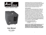
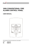
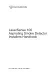
CIRRUS PRO
ASPIRATING FIRE DETECTOR
User Manual and Responsibilities
Protec Fire Detection (Export) Ltd, Protec House, Churchill Way, Nelson, Lancashire. BB9 6RT.
Telephone:
Fax:
+44 (0) 1282 717171
+44 (0) 1282 717273
NOTICE
THESE INSTRUCTIONS DO NOT PURPORT TO COVER ALL DETAILS OR VARIATIONS IN
EQUIPMENT NOR TO PROVIDE FOR EVERY POSSIBLE CONTINGENCY TO BE MET IN
CONNECTION WITH THE INSTALLATION, OPERATION OR MAINTENANCE OF CIRRUS PRO
SYSTEMS.
SHOULD FURTHER INFORMATION BE DESIRED OR SHOULD PARTICULAR PROBLEMS ARISE,
WHICH ARE NOT COVERED SUFFICIENTLY FOR THE PURCHASERS PURPOSES, THE
MATTER SHOULD BE REFERRED TO PROTEC FIRE DETECTION (EXPORT) LTD.
INSTALLATION SHOULD BE PERFORMED BY AUTHORISED PERSONNEL, WHO ARE TRAINED
AND FAMILIAR WITH INSTALLATION PROCEDURES.
LIMITED WARRANTY
Protec Fire Detection (Export) Ltd, warrants the Aspirating Fire Detector described herein to be free
from defects in material and factory workmanship and agrees to repair such instruments which under
normal service disclose the defect to be the fault of Protec Fire Detection (Export) Ltd manufacturing.
Protec Fire Detection (Export) Ltd's obligation under this Warranty relates to the original purchaser
and is limited to the return of the purchase price or, at Protec Fire Detection (Export) Ltd's sole
discretion, to the repair or replacement of the detector or any of its parts which, in our opinion and
upon examination prove to be defective. For this Warranty to be in effect, notification of any material
or part alleged to be defective should be made to Protec Fire Detection (Export) Ltd, in writing, within
12 months from date of delivery.
This Warranty shall not apply to a detector which has been (1) subject to misuse, negligence or
accident; (2) connected, installed, operated or adjusted other than in accordance with instructions
furnished by Protec Fire Detection (Export) Ltd; (3) repaired, modified or worked on by someone not
authorised by Protec Fire Detection (Export) Ltd, so that in our judgement the performance or
reliability of the detector has been impaired.
We reserve the right to make replacement with equivalent merchandise and to make changes at any
time in the specification, design or construction of the instrument without incurring obligation to make
any commensurate changes in units previously delivered.
Protec Fire Detection (Export) Ltd, assumes no liability for consequential or contingent damages for a
defective detector covered by this Warranty, failure of delivery in whole or in part, or for any other
cause. This Warranty and the writing to which it is attached constitutes the understanding of the buyer
and seller so that no terms, conditions or agreements purporting to modify the terms hereof shall be
binding unless made in writing and signed by an authorised agent of the home office of Protec Fire
Detection (Export) Ltd.
All rights reserved. Copyright ©2005, Protec Fire Detection (Export) Ltd.
WARNING!
INSTALLATION AND MAINTENANCE SHOULD ONLY
BE PERFORMED BY PROTEC FIRE DETECTION
(EXPORT) LIMITED OR BY THEIR AUTHORISED
DISTRIBUTOR / REPRESENTATIVE FAMILIAR WITH
THESE SYSTEMS.
93-523-23 Issue 3.2
Page 2 of 20
CirrusPro User Manual
Issue
1
2
3.1
3.2
First Issue
Minor Changes – Display Software v1.09
UL Information introduced
References to Bellows removed
93-523-23 Issue 3.2
Page 3 of 20
Date
26/04/05
02/06/05
14/02/06
2/11/12
Author
jlh
jlh
sb
jlh
CirrusPro User Manual
CONTENTS
1.0
1.1
1.2
1.3
2.0
2.1
3.0
3.1
3.2
4.0
4.1
4.2
5.0
INTRODUCTION....................................................................................................................... 5
Models and Equipment Covered ............................................................................................... 6
UL and ULC information. Pro100, 200, 200+, 200D, 200D+, 200DSC and 200DSC+............. 7
UL and ULC information Pro X4 ............................................................................................... 9
PERIODIC CHECKS AND MAINTENANCE .......................................................................... 11
Periodic Checks ...................................................................................................................... 11
2.1.1 Daily Checks .................................................................................................................. 11
2.1.2 Three-monthly Checks ................................................................................................... 11
2.1.3 Annual Checks ............................................................................................................... 11
USER GUIDE .......................................................................................................................... 12
Front Panel Indications and Controls ...................................................................................... 12
Panel Display .......................................................................................................................... 12
3.2.1 Main Options Menu ........................................................................................................ 14
3.2.2 Real Time graph............................................................................................................. 14
3.2.3 Unit/pipe text .................................................................................................................. 15
3.2.4 Event Log ....................................................................................................................... 15
3.2.5 Historic Graph ................................................................................................................ 16
3.2.6 Security Code ................................................................................................................. 16
3.2.7 Service Information ........................................................................................................ 17
FAULT FINDING ..................................................................................................................... 18
Fault List .................................................................................................................................. 18
Indicating Fault Codes on the Detector Unit ........................................................................... 18
DETECTOR SPECIFICATION................................................................................................ 19
93-523-23 Issue 3.2
Page 4 of 20
CirrusPro User Manual
1.0
Introduction
This manual details the methods employed to install, commission and service the CirrusPro Series
Aspirating Fire Detectors.
Background Background
It is known that particles smaller than the wavelength of visible light occur spontaneously as a material
is overheated, and in numbers far above those present in a normal ambient environment. CirrusPro
Detectors utilise the Wilson Cloud Chamber principle to detect the sub micron particles that are
generated at the incipient, and all other stages of fire.
A filtered air sample is delivered to the detector via a centrifugal blower, a portion of which is diverted
into a humidifier. At approximately 100% relative humidity, the sample is directed to the Cloud
Chamber where, because of cooling, due to rapid vacuum expansion, water condenses onto the small
particles and forms a ‘cloud’.
Consequently, the thermally generated particles cause many droplets to form into the cloud, which is
then detected by the measuring system of the Cloud Chamber. The density of the cloud being
proportional to the number of particles present.
The result is a continuous signal that corresponds to the particle concentration. This signal is used to
provide a staged alarm sequence with four alarm levels.
The CirrusPro Detectors are self-supervised systems that continuously monitor for correct operation.
Any problem is immediately reported with the front panel Fault LED, buzzer and the operation of a
Fault relay.
CirrusPro Series Detectors locally store fault data, background particle concentration and event data.
These can be accessed and plotted with optional Cirrus Windows Software.
An optional panel display can be fitted that allows configuration options and full data to be displayed.
This can be mounted local to the detector or remote and networked to up to 32 devices (detectors or
panel display).
93-523-23 Issue 3.2
Page 5 of 20
CirrusPro User Manual
1.1
Models and Equipment Covered
CirrusPro 100
Up to 100m of 25mm diameter sampling pipe. Single sampling pipe ‘inlet’ port.
CirrusPro 200
Up to 200m of 25mm diameter sampling pipe. Four, sampling pipe ‘inlet’ ports.
CirrusPro 200D As CirrusPro 200 with built in Display Panel (See CirrusPro RDP).
CirrusPro 200DSC As CirrusPro 200D but with four, scanned, sampling pipe ‘inlet’ ports.
CirrusPro 200+ (no display), 200D+ and 200DSC+ with larger ‘blower’ for longer pipe runs.
CirrusPro X4 As CirrusPro 200DSC with up to 40 sampling heads (not suitable for 25mm diameter
sampling pipe).
CirrusPro RDP Remote Display Panel. Multifunction Quarter VGA back lit LCD and controls.
93-523-23 Issue 3.2
Page 6 of 20
CirrusPro User Manual
1.2
UL and ULC information. Pro100, 200, 200+, 200D, 200D+, 200DSC and
200DSC+
The following information is required to ensure the units compliance with the UL listing for UL 268 &
CAN/ULC-S529-02
Detection Principle:
Cloud Chamber
Maximum Protected Area:
Pro 100
Pro 200
Pro 200+
Pro 200D
Pro 200D+
Pro 200DSC
Pro 200DSC+
10,000 square feet (929.03 square meters)
20000 square feet (1858.06 square meters)
20000 square feet (1858.06 square meters)
20000 square feet (1858.06 square meters)
20000 square feet (1858.06 square meters)
20000 square feet (1858.06 square meters)
20000 square feet (1858.06 square meters)
Maximum Coverage
Per Sample Head or Point:
30’ x 30’ (9.144m x 9.144m)
Number of Zones:
Pro 100
Pro 200
Pro 200+
Pro 200D
Pro 200D+
Pro 200DSC
Pro 200DSC+
1 Zone
1 Zone
1 Zone
1 Zone
1 Zone
Field Programmable up to 4 Zones
Field Programmable up to 4 Zones
Maximum Number of
Sampling Heads or Points:
100
Minimum Number of
Sampling Heads or Points:
2 per pipe
Alarm Thresholds:
4 per Zone
Sampling System DT
(Transport Time)
Maximum Allowed
Pro 100
Pro 200
Pro 200+
Pro 200D
Pro 200D+
Pro 200DSC
Pro 200DSC+
120 Seconds
120 Seconds
120 Seconds
120 Seconds
120 Seconds
1 Zone system 120 Seconds
2 Zone system 90 Seconds
3 Zone system 75 Seconds
4 Zone system 60 Seconds
1 Zone system 120 Seconds
2 Zone system 90 Seconds
3 Zone system 75 Seconds
4 Zone system 60 Seconds
Sampling System DT
(Transport Time)
Minimum Allowed:
6 Seconds (on Multi Zone systems)
Controls:
Push Buttons
93-523-23 Issue 3.2
Page 7 of 20
CirrusPro User Manual
Indicators:
Pre-Alarm, Fire 1, Fire 2, Fire 3 LED’s
Power and Fault LED’s
LCD display for Particle levels, Alarm and Fault Text
Power Requirements:
21-27V dc. Unit must be used with a UL 1481 Listed Power
supply
Contact Ratings:
1A at 30V dc
4 Alarm relays per zone (Non-monitored volt free contacts)
1 Fault relay (Non-monitored volt free contact)
Outputs:
Audible alert, RS232 Serial Computer Interface
Inputs:
Programmable
(Reset, Disable, Gain, Isolate, External Fault, Mains Fail,
Battery Fault)
Data Retention:
200 events “Event Log”, Historic Particle Graph
Water Requirements:
Distilled, replenished as required, dependent upon
environment
Note: Low ambient humidity(<50% R.H) or high ambient
temperature (>30C) conditions will increase the water usage.
Unit Operating Temperature:
32-100° F (0-37.8° C) ambient
Relative Humidity:
0-95% non-condensing ambient
Cabinet:
Pro 100
Pro 200
Pro 200+
Pro 200D
Pro 200D+
Pro 200DSC
Pro 200DSC+
11.22” x 8.47” x 5.51” (285mm x 215mm x 140mm)
11.22” x 8.47” x 5.51” (285mm x 215mm x 140mm)
11.22” x 8.47” x 5.51” (285mm x 215mm x 140mm)
11.22” x 8.47” x 5.51” (285mm x 215mm x 140mm)
11.22” x 8.47” x 5.51” (285mm x 215mm x 140mm)
17.32” x 15.15” x 5.51” (440mm x 385mm x 140mm)
17.32” x 15.15” x 5.51” (440mm x 385mm x 140mm)
Air Sampling System:
Gain Settings
(Sensitivity):
93-523-23 Issue 3.2
The piping diagram for each system will be supplied by
Protec Fire Detection (Export) or an authorized
representative. This diagram will indicate tubing size, as well
as approximate lengths to each sampling point.
1-10 (1 = Minimum, 5 = Intermediate, 10 = High)
Note: If Fire 3 is set to a Gain of 1, Fire 3 Alarm Level shall
not exceed 25%".
Page 8 of 20
CirrusPro User Manual
1.3
UL and ULC information Pro X4
The following information is required to ensure the units compliance with the UL listing for UL 268 &
CAN/ULC-S529-02
Detection Principle:
Maximum
Intended Protected Area:
Cloud Chamber
43,200 square feet (4013 square meters) 4 zones total
10800 square feet (1003.25 square meters) per zone
900 square feet (83.604 square meters) per sampling head or
point
Maximum Coverage
Per Sample Head or Point:
30’ x 30’ (9.144m x 9.144m)
Number of Zones:
Field Programmable up to 4 Zones
Maximum Number of
Sampling Heads or Points:
48
Minimum Number of
Sampling Heads or Points:
2 per Zone
Alarm Thresholds:
4 per Zone
Sampling Manifolds:
Minimum 2 per zone
Maximum 12 per zone
Zone Manifold:
1 per Zone
Sampling System DT
(Transport Time)
Maximum Allowed:
1 Zone System
2 Zone System
3 Zone System
4 Zone System
120 Seconds
90 Seconds
75 Seconds
60 Seconds
Sampling System DT
(Transport Time)
Minimum Allowed:
6 Seconds
Controls:
Push Buttons
Indicators:
Pre-Alarm, Fire 1, Fire 2, Fire 3 LED’s
Power and Fault LED’s
LCD display for Particle levels, Alarm and Fault Text
Power Requirements:
21-27V dc Unit must be used with a UL 1481 Listed Power
supply
Contact Ratings:
1A at 30V dc
4 Alarm relays per zone (Non-monitored volt free contacts)
1 Fault relay (Non-monitored volt free contact)
Outputs:
Audible alert, RS232 serial computer Interface
93-523-23 Issue 3.2
Page 9 of 20
CirrusPro User Manual
Inputs:
Programmable
(Reset, Disable, Gain, Isolate, External Fault, Mains Fail,
Battery Fault)
Data Retention:
200 events “Event Log”, Historic Particle Graph
Water Requirements:
Distilled, replenished as required, dependent upon
environment
Note: Low ambient humidity (<50%R.H) or high ambient
temperature (>30C) conditions will increase the water usage.
Unit Operating Temperature:
32-100° F (0-37.8° C) ambient
Relative Humidity:
0-95% non-condensing ambient
Cabinet:
17.32” x 15.15” x 5.51” (440mm x 385mm x 140mm)
Air Sampling System:
The piping diagram for each system will be supplied by
Protec Fire Detection (Export) or an authorized
representative. This diagram will indicate tubing size, as well
as approximate lengths to each sampling point.
Gain Settings
(Sensitivity):
1-10 (1 = Minimum, 5 = Intermediate, 10 = High)
Note: If Fire 3 is set to a Gain of 1, Fire 3 Alarm Level shall not exceed 25%".
93-523-23 Issue 3.2
Page 10 of 20
CirrusPro User Manual
2.0
Periodic Checks and Maintenance
The CirrusPro continuously adjusts its monitoring functions by means of feedback loops, ensuring a
minimum of maintenance. To ensure continued proper operation, the system must be checked:
•
•
•
•
•
•
Daily by the User.
Every three months by Protec Fire Detection (Export) Ltd or an authorised representative.
Whenever building alterations have been performed which could affect the system's operation.
Whenever equipment within the protected area has been altered which could affect the system's
operation.
During a fault condition.
After any alarm condition.
The following are based on average conditions. Because of the wide range of possibilities in various
applications, the frequency of periodic checks and maintenance may have to be adjusted accordingly.
2.1
Periodic Checks
2.1.1 Daily Checks
The following must be performed EVERY DAY by the system User:
•
•
•
•
Check system indicates a healthy condition.
Any fault indicated should be recorded in the system logbook and investigated.
Determine the extent of the fault and decide whether special actions (such as fire patrols) are needed.
Check that any fault reported previously has been attended to.
2.1.2 Three-monthly Checks
The following must be performed EVERY THREE MONTHS by Protec Fire Detection (Export) Ltd or an
authorised representative:
•
•
•
•
•
•
•
•
•
•
•
Check the Event Log to determine any abnormalities.
Refill the Water Bottle with distilled or de-ionised water.
Check that all Tubing is properly connected, with no kinks.
Check Inlet integrity.
Check dc supply voltage level.
Check Alarm and Gain levels as per specification.
Check Vacuum level.
Check the Sampling System airflow readings.
Check Transport times at furthest Sampling point on each pipe.
Check the LED current.
Check and replace, where necessary, cloud chamber filters.
Caution: Do not neglect regular filter changes. Although a used filter may appear to pass the
recommended flow, the dust it has trapped can cause an increase in the retention of sub micron fire
particles, reducing system effectiveness.
2.1.3 Annual Checks
The following must be performed EVERY TWELVE MONTHS by Protec Fire Detection (Export) Ltd or an
authorised representative:
•
•
•
Carry out the three monthly checks as previously described.
Inspect and clean if necessary the Flow Thermistors.
Inspect and clean if necessary Cloud Chamber and Optics.
93-523-23 Issue 3.2
Page 11 of 20
CirrusPro User Manual
3.0
User Guide
3.1
Front Panel Indications and Controls
All CirrusPro models have a small control panel with 6 LED indicators and 2 push buttons:
Indications
There are 4 levels of alarm, Pre Alarm and Fire levels 1, 2 and 3. The points at which these levels are
set can be examined in the Sensitivity Settings section of the commissioning menu on the PC.
Power indicator is On when the power is present but flashes when a remote power supply fault is
detected. If the power indicator is off there is no power to the unit.
Controls
Silence Reset -
3.2
Releases the activated alarm relays and / or mutes the internal buzzer.
Performs the Silence function and clears any current fire conditions.
Panel Display
On powering up the display will show the number of units found on the network.
The text at the bottom of the display corresponds to the push buttons below the display. By holding
down a button, its function will auto-repeat.
Mute is used to mute the system buzzer.
Pressing Menu lists the units found on the network.
93-523-23 Issue 3.2
Page 12 of 20
CirrusPro User Manual
The Up and Down keys move between the units.
Select accepts the current highlighted detector unit, request status and displays the following,
depending on model:
Showing the current particle levels for the sample pipes.
Pressing Menu requires a password.
Use the + and – to select the number and press Enter. The low security codes is factory pre set to
112233, although, this can be changed from the display see section 3.2.6.
When all the digits have been entered press Accept.
93-523-23 Issue 3.2
Page 13 of 20
CirrusPro User Manual
3.2.1 Main Options Menu
The menu options available are as shown.
Use the Down Key to move to the required option.
Press Select to move to that menu Option.
Pressing Exit from this menu will revert back to the
particle level display. It will then be necessary to
enter the security code again to return to the Main
Options Menu.
General rules:
Up and Down – Move through the various options available on the menus.
Select
– Changes highlighted value or moves to a further menu
+ and –
– Increase and decrease the highlighted value
Accept
– Stores changes in the detector unit (when necessary). Some changes require the
unit to be reset before being fully implemented.
Exit
– Leaves the current menu. Note that some changes remain indicated locally. These
are not sent to the detector unit until accept is pressed.
Buttons will auto-repeat after being held down for a short time.
3.2.2 Real Time graph
This displays a real time graph of the current particle and alarm levels showing about 5 minutes.
Use + and – to view other Pipes (where available).
93-523-23 Issue 3.2
Page 14 of 20
CirrusPro User Manual
3.2.3 Unit/pipe text
The display receives the text from the unit.
Use Up, Down and Edit to select the text to be edited.
Then use Left, Right and Exit keys to select a character.
To change a character, use + and – to scroll through the symbols and alphabet in the following order:
!”£$%&’()*+,-./0123456789:;<=>?@ABCDEFGHIJKLMNOPQRSTUVWXYZ[\]_’abcdefghijklmnopqrstuvwxyz
After editing as required, press Exit to return to the Unit / Pipe Text display.
Press Accept, when all the text has been modified, to send the text to the Unit.
Pressing Exit leaves the menu with the text unchanged (even after editting) if Accept has not been
pressed.
3.2.4 Event Log
The Event Log stores the last 128 events on the unit.
The latest events are displayed first, with earlier events displayed by pressing Next.
Pressing ‘Both’ changes the display to show just Fire events.
93-523-23 Issue 3.2
Page 15 of 20
CirrusPro User Manual
Pressing Fires changes the display to
show just Fault events.
Pressing Fault returns to showing all events.
3.2.5 Historic Graph
The Historic Graph shows a period of about three days, with about 10 days stored. The amount of
data is dependent on what has happened during the recording period. The amount of data stored
increases during fire and pre alarm events.
3.2.6 Security Code
On opening this screen, the display shows 0. Use + and – to increase or decrease the value and
Select (Sel) to add another digit. Use no more than 9 digits and the first digit cannot be 0.
When the required code is displayed press Accept to immediately update the unit. It is very important
to log this code as it cannot be extracted from the unit.
93-523-23 Issue 3.2
Page 16 of 20
CirrusPro User Manual
Pressing Exit leaves this display without changing the code.
Record the User Security code here:
User Code
3.2.7 Service Information
Acceptable Values:
Pump Pressure Supply voltage LED current is Airflow
-
> 5.7 psi
19V to 30V
0.26mA to 5.67mA
Refer to Pipe Calculation
Average time between fills
93-523-23 Issue 3.2
-
Usually 4 to 6 days, depends on local conditions.
Page 17 of 20
CirrusPro User Manual
4.0
Fault Finding
Internal diagnostics monitor for faults that may normal running.
4.1
Fault List
The list below shows all the possible faults and their codes:
1 Processor fault
2 Corrupt eeprom
3 Supply fault
4 No water
5 Chamber seal
6 Vacuum fault
7 LED fault
8 Water fill fault
9 Airflow fault
10 Stack overflow
11 Unit isolated
12 Low supply voltage
13 Algotec fault
14 Unit cold Fault
15 Unit disabled
16 Expansion board fault
17 External fault
18 Battery Fault
19 Mains Fault
20 Sample blocked
21 Purge blocked
22 Zone Override Enabled
The numbers correspond to the Fault Codes, which can be extracted as described below.
4.2
Indicating Fault Codes on the Detector Unit
The CirrusPro can pulse the Fault LED to indicate fault code of current Faults or the last fault if there
are no current Faults.
When the unit is in Fault, press and hold the Silence button.
The Fault LED will illuminate for 5 seconds, then pulse a number of times indicating the fault code.
When the code is complete, the Fault LED will illuminate for 5 seconds.
The code will repeat or further fault codes will be indicated.
Faults are indicated in numeric order i.e. Code 3 before Code 4 etc.
Fault LED indicating one fault (fault code 4 – No water).
Fault LED indicating two fault codes (fault codes 3 & 4).
The sequence will repeat until the Silence Button is released.
93-523-23 Issue 3.2
Page 18 of 20
CirrusPro User Manual
5.0
Detector Specification
Physical Data varies with model and are not given here
Supply Voltage:
19 - 30VDC
Humidity:
10 - 95%RH, non-condensing
Temperature:
0 - 38°C
IP Rating:
IP30
Cable Access:
20mm knock
Cable Termination:
Screw terminal blocks
(0.2 - 2.5mm2, 30 - 12AWG)
Pipe ID:
19 to 25mm (preferred OD 25mm)
Alarm Indications:
Pre-alarm, Fire 1, Fire 2, Fire 3.
Other Indications:
Supply Healthy, General Fault.
Sensitivity Range:
20,000 particles per cc to 3 million particles per cc
Sensitivity ranges:
10 programmable.
Programmable Inputs: 4 monitored inputs for Isolate, Silence, reset and ‘Sensitivity Change’ feature.
Open circuit voltage: ~16V, Max applied voltage: 30V
Max closed circuit resistance: 1500 Ohms
Output Relays:
4 Programmable Fire Relays
1 Fault Relay
4 Additional / Pipe on the expansion board for sampling systems
All Rated: 0.3 A at 125 VAC; 1 A at 30 VDC Rated carry current 1 A
Max. switching voltage 125 VAC, 60 VDC Max. switching current 1 A
Auxiliary (VS) supply: 27.6V, Current limited to 300mA
Power fault input:
Fault level < 2.5V
Event Log:
128 events stored on FIFO basis
Data Retention:
10 day historical graph.
Sensitivity Settings:
7 day programmable settings with 3 time zones per day.
AlgoTec
Environmental learning, interactive decision making algorithm software to
continuously monitor background particles levels and enable optimum
detector sensitivity and alarm thresholds.
Airflow Monitoring:
‘High Airflow’ and ‘Low Airflow’ fault monitoring.
93-523-23 Issue 3.2
Page 19 of 20
CirrusPro User Manual
Cirrus Pro Series Aspirating Fire Detectors Worldwide Manufacturer
PROTEC FIRE DETECTION (EXPORT) LIMITED
Protec House,
Churchill Way,
Nelson,
Lancashire,
England. BB9 6RT.
93-523-23 Issue 3.2
Phone: +44 1282 717171
Fax:
+44 1282 717273
E-mail: [email protected]
Page 20 of 20
CirrusPro User Manual