1
YOUR ONE -STOP SOURCE OF ELECTRONICS INFORMATION
MARCH 1991 $2.95
CANADA $3.95
THE MAGAZINE FOR ELECTRONICS & COMPUTER ENTHUSIASTS
Project Prevents Costly
Unauthorized -900 and
976 Toll -Call Dialing
Triple-Head Photo Flash System (p. 47)
i
Multiple- Source Lighting
For Pro Photo Portraits
Also:
Build A Digital Signal Generator And
Computer Experimenter Platform
A Mini-Rawer AM Transmitter
For No- License Experimenting
Working With Electronic
Strain Gages
TRANSMITTER
Dallas Semiconductor Cyber-Card 4M SRAM (p. 68)
03
o
11
74820 0855
Plus: Evaluating Power Up! "Calendar Creator Plus" and "Top Priority" Personal
Information Manager Software A New SCSI -II Adapter, Ruggedized SRAM and
BurstRAM New Electronic & Computer Products Latest Technical Books, Free
Literature and News ... more.
MICROSCIENCE MODEL
111 MB(Unformatted) 93
Access Speed
3 -1/2" w /Frame -RLL
Lkr/ri/lED'
4090
MB(Formatted)
-18
MS BRAND NEW
Access Track
to Track
4 MS
VOICE COIL DRIVE - 1 Year Warranty
QUANTITY DISCOUNTS AVAILABLEI
8 Bit 8 16 Bit
RLL Controllers Available - Call
-
WE WILL TRY TO BEAT ANY PRICE ON ANYTHING FROM ANYWHERE !!!
A TRULY PROFESSIONAL STAFF WITH A COMMITMENT TO SERVICE!!!
PRINTER POWER
MONITOR MANIA
GENICOM -5010 LASER
10 Pages Per Minute
300 DPI
PRINCETON GRAPHICS
-
HP COMPATIBLE
Ultra Sync 14 Color Monitor
1.735 MB of Memory
Six Resident Fonts Parallel /Serial Includes: Toner
Year Warranty From Genicom
1
%
-v
AMAZINGIIII
$
Quantity Discounts
79 9
14" Multisync
I
Available
FRONT - BOTTOM - REAR PAPER FEED
Paper Rack Available Stacks Printed Paper - Only $12.95
Easy Change Cartridge Ribbons- Available
90
Quantity Pricing
W
BRAND
-
CALL
CITIZEN MSP
NE,
50
Optional!
&
1
Z28\
DOT PITCH
300 CPS 50 NLQ- Narrow Carriage 9 -Wire Epson /IBM
Compatible Push or Pull Tractor Zero Tear Off Top or Bottom
Feed Automatic Paper Loading 8K Buffer Parallel Interface
18 Month
200 CPS Wide Carriage - Color Printer
24-Pin -192 CPS-63 NLO- Narrow
Laptop Printer - 24 Pin - 180 CPS
24 Pin - Narrow - 135 CPS -54 NLQ
120 CPS - 60 CPS Exp. -Narrow Carriage
-
BRAND NEW
75%
...
IBM Compatible Interface Card
AT&T PAGE POWER SOFTWARE
(Draw, Scan and Fax Package)
List $1190
800
1066 Sherman Avenue
Hamden, CT 06514
FAX W3-248-8680
8680
FAX ORDERS AND BIDS ACCEPTED?
ORDERS
ONLY
99
16-Colors - 640x200
90 Day Warranty - Model 3584
CRT-327 -12" TTL
=0 AT &T
Black White Monitor
&
90 Day Warranty
INCLUDES AT &T 1024HP Card
BRAND NEW
List $1390
$119
NCR 15" Green - TTL
$
$2991 Save over 75%
Works on All IBM AT/XT's 8 Compatibles
6 -$115, 12 -$109, 24 -$105, Over 24 -CALL
-
with NCR
ONLY
-
-
BRAND NEW
Monitor Card 640x400
1
List
YEAR
warranty $438
* * Electrified Discounters *
7PM
List $550
ONLY
Tilt & Swivel
Microsoft 1 Year Warranty
Windows AMAZING
3.0 Upgrade
ONLY
HOURS: Mon -Thurs 9AM
Fri Sat 10AM -6PM
COLOR
24 -$149
Over 24- CALL
6- $159
12- $155
200 DPI Full- Page /400 DPI Half -Page
Half -Tone feature for Photographs
Quantity Discounts Available
-
Quantity
3 -$165
Includes - Microsoft Runtime Windows Resolution
SAVE
OVER
ONLY $149
BRAND NEW
MODEL SC -60 Sheet Feed Series
Includes
Includes
-
-'
Extra Card
14" - Cotor Monitor w /Color Card
80 CPS -Ltr, Olty w /Sheet Feeder -Refurbished
330 CPS - 66 NLQ - Wide Carriage
180 CPS - 34 NLO - Wide -Heavy Outy
AT &T FULL -PAGE SCANNER
List $1190
STB -VGA
1
SPERRY - RGB COLOR
LIMITED QUANTITIES!!
f
(:$2 9 9,1
C3ilt
Color - 600x200
Green /Amber Switch, Tilt & Swivel
MoD MV\.
ONLY
$ 269
s 499
New
389
New$ 299
$ 299
New $ 279
New E 229
New E 229
New $ 119
YEAR WARRANTY
2QG1D GLOW
14" -RGB
MSP-50 Options
Ribbons Available
Color Kit (7 Colors)
$59
- CALL
Serial Interface
$49 Quantity Price:
Font Card Sans Serif/Orator $59 3 @$249, 6 @$245, 12 @$239, 24 @$229
PRINTER POWER
.31 Dot Pitch
-
VGA -PC -Model 12HR
Swivel- 720x480 -Anti -Glare Screen
AMDEK 600T
Manufacturers Warranty
DIABLO -OBOIF
PANASONIC KXP -1695
CENTRONICS-136B
IBM 5182-Deltas
PANASONIC KXP -1124
TOSHIBA 301)Below Cost)
SEIKOSHA SL -80AI
RITEM AN by C.ITOH
640x480
-
AMSTRAD COLOR VGA
$399)
-
VGA COLOR
UNBELIEVABLE VALUE
List $1,995
WarraDay
nty
Dot Pitch
IBM Model #7544/S01
High Performance Graphics
90 Day Warranty
(BRAND)
Heavy Duty Wide Carriage (132 Column)
Prints Black, 4 Colors, and 8 Colors BiDirectional Dot Matrix
BRAND NEW
9 Wire -Parallel Interface Tractor Included
-
IBM
13" Viewing Area
IBM 5182 COLOR PRINTER
200 CPS Draft - 110CPS Correspondence 35 CPS NLQ
.28
;$ 399;
Refurbished- Mint Condition List $899
,,,,//
U//,AY,
Ultra H¡ -Res
Full 90 Day Warranty
from Princeton.
BRAND NEW
List
436955/Ì
-
800x600
`Q
(800)
678V -8585
Customer Service 8 Technical Support
(203) 287 -1976
Dealer Inquines invited
30 -DAY MONEY
M Now
BACK GUARANTEE!
Full Refund of HARDWARE
Price on all Advertised Products
q
Catalog Sent ,vile
V/i4
ALI
Orders
art a u.
urwss
hid
we Car, D.corN.O A00 2
to Masa.Card, vr., a AMEX Na
,upon.tle la bpogr.v,Nal .ra. Prawn
/2%
tu,t name Cono
ax W- t.. NY sales Add NY
Ouanale. we Wawa Nam do na
q.a c aangs
T.residents .OE
.
k.gM. Alm
3
..r,3 ax
p.wuvounpa^r a.ot, d...nnr 20x
C..roa.g
,r.man on WI .a,m..
anp.aa.t, r na yv.r.,t..a san..Y.a..
meow may te r.4rO.M0. IBM r
a irNrrM/ml
nA,d
t-
rS.WWia.kl.t! a.,kc
EErírifEd
SHARP - MZ -100 LAPTOP
Fast 10 MHz - 8088 CPU High -Definition Backlit Supertwist Display
640 x 400 Resoution with 4 Shades of Gray 2 - Internal 3.5- - 720K Drives
640K of Ram - Expands to 1.6 MB
Battery (Ind.) or AC Operation - 100 IBM Compatible
90 Keys with Numberic and Cursor Keypads
Paralel /Serial /Clock - MB -DOS 3.3 & GW Basic 3.22
Might 10.8 lbs.
1 Year Warranty from Sharp
Sharp Refurbished - Brand New Corlßition
-
WE WILL TRY TO BEAT ANY PRICE ON ANYTHING FROM ANYWHERE!!!
A TRULY PROFESSIONAL STAFF WITH A COMMITMENT TO SERVICE !!!
LIST $1995.
549
AMAZING
COMPUTER COUNTRY
AMAZING
FREE
Options Avails ble! - Quantity Discounts!!
$1699
ONLY
120 Day
On -Site Service
GOLDSTAR
-
386/20 MHz
40 MB System & Goldstar
VGA
Color Monitor
-
ALPHAWORKS
SOFTWARE
FREE
386SX 16MHz
512K Installed - Baby AT Case - 200 Watt
power Supply - AMI BIOS - ZERO WATT STATE
- 80387SX - Socket - Up to 4MB
on the Motherboard - 101 Deluxe Keyboard
8 -Slots - Reset and Turbo Buttons - Keylock
3 (1 /2HT, 5 1/4 ") and 2 (1 /2HT, 3 1/2 ")
Drive Bays - Clock/Calendar
1 -Year Warranty
Additional On -Site
Service Available
System Includes:
80386-20 MHz Computer
1MB -High Speed DRAM -expands
to 10 MB (Memory Upgrades Avail.)
40 MB Seagate Herd Drive - 28 MS
(Larger Drives Available)
1.2 MB Floppy Drive
VGA Monitor Card - 16 Bit
14" VGA Color Monitor- Model 1425 Pus
with Tilt & Swivel: Upgrades Available
Style Keyboard
DOS 3.3 with Basic
8 - Slots (132 Bit, 5 -16 Bit, 2 -8 Bit)
ParalleVSeriaVClock Calendar
200 Watt Power Supply - 80387 Socket
101
$599
Novell Certified
Wordprocessor, Spreadsheet, Data Base
Manager, SpelIchecker and Thesaurus,
Communication Software and Tutorials.
[WARRANTY
v
1- Year Parts &
Warranty
-
GOLDSTAR TOLL FREE CUSTOMER SUPPORT LINE
386/25 and 386/33 MHz Systems
Available Now
CALL!
Goldstar XT /Turbo and 286/16 MGHz Systems are Available - CALL
SYSTEM OPTIONS
AWESOME
0286 -TURBO 10/16 MHz
SUPER SYSTEM OPTIONS
Add a2rd360K5 00 Drive
Add a 10MB Drive
Ind. Controller
Ind. Controller
Add a 20MB Drne
Fully IBM Compatible
Zero Walt State!!
8088 -1 -TURBO
Add a 30MB Drive
Add a 40MB Drive
512K Installed - Full Size Case 200 Watt Power Supply
Award BIOS 101 Keyboard Up to 4MB on Motherboard
8 VO Slots 80287 Socket Reset and Turbo Button
Keylock and 3 LEDS Clock/Calendar
1 YEAR WARRANTY
FCC Approved Class B
Produced by JCC
-Drive IBM Compatible System
with 256K Memory!!
-
-Hal Height, 360K, 51/4. Drive INSTALLED
Dual Speed - 437 MHz and 10/12 MHz - TURBO
256K Installed 8 Slots 8087 Socket 150 Watt Power
Supply Deluxe Keyboard Full Size Case for 4 1/2 HT
Drives 1 Year Parts 6 Labor Warranty on Base Unit
Produced by JCC
1
NOW 10 /12MHz
IMPOSSIBLE PRICE"!
Quantity Pricing
Available
$2491
NOW
NOW
16MHz
16MHz
HARD DRIVE DEALS
AT &T 40 MB Tape Backup Kit
$199
MINISCRIBE 3675-62MB -RLL-5 1/4-NEW
$299
MINISCRIBE 8450-4OMB- RLL -31/7-NEW
$199
SEAGATE- ST- 138R -32MB -RLL -3 1/2"
$199
SEAGATE ST -4051
40MB
Full HT
-
MFM
$189
MINISCRIBE- 8438F -30MB- RLL -31/2- -NEW
$179
SEAGATE -ST- 238-30MB -RLL -51/4 -12HT
$179
TANDON -TM- 262 -20MB- MFM -31/2
$149
WESTERN DIGITAL- MFM -XT Cont. w /Cables
$ 49
RLL Controllers for XT and AT's Available
CALLI
MINISCRIBE Warranty -6 Months -NEW DRIVES
Seagate & Tandon Warranty -90 Days-OEM Pulls
QUANTITY PRICING AVAILABLE
CALLI
-
1066 Sherman Avenue
Harden, CT 06514
FAO
W3.248-8680
FAO ORDERS AND BIDS ACCEPTED!
$249
-
-31/2
5f4
-3 fir
DOS
-
Parallel or Serial Cad
VGA Monte and VGA Card
141 RGB Color Mor torw/CObr Card
Color Graplves vP mler Pon
$19
$399
$149
$39
SAVE 75%
BRAND NEW (IBM PC /XT or Compatible) BRAND NEW
1000% FASTER THAN A REGULAR PC
Replace Your Old CPU with an Intel 80286 Microprocessor
is
A
e
weggram
(800) 678-8585
Customer Service b Technical Support
(203) 287 -1976
110MB Hard Drive- Special
LARGER HARD DRIVES AVAILABLE
IRAN 20MB -Tape Bads -Up System
AT&T 40 MB Tape Backup Kit
AT Para1IQt5erlal /Game Card
E 29
Card
$99
121 Black & While TTL and AT &T Cad $99
Monochrome Hi Res
TTL
$59
-
AT &T
121
Monodrome Graphics Card MIA Printer Port $39
DRIVE WARRANTIES VARY
CALL FOR DETAILS
-
-
LIST
$69.95
Call for Pricing!!!
Dealer Inquines Invited
30 -DAY MONEY
BACK GUARANTEE!
Full Refund of HARDWARE
Price on eil Advertised Products
q
Cal alog Sant with
CIRCLE NO. 27 ON FREE INFORMATION CARD
Computers
Printers
FREE
er e
(wed*
$199
$279
5499
$399
CALL
$149
$199
Dr me
ALPS Apple Brother Canon Citizen
C -ROH
Diablo Diconix (Kodak) Epson Fujitsu Genicorn
Hewlett Packard
IBM Mannesmann Tally
NEC Okidata Panasonic Printronics
Seikosha Televideo Texas Instruments Toshiba
Minutes
Virtual) UNLIMITED. Full Mnfr Warranty and Technical Stppon
ecounte
- Hard
60MB- Hard Drive
sOMB- Had Oran
Monitors
DAC -EASY LIGHTNING
Substantiel Quantity
40MB
Amdek Apple AT&T Goldstar Hitachi
IBM Magnavox Mitsubishi NCR NEC
Pacard Bell Panasonic Princeton Graphics
Samsung
Seiko Sony Tatung Zenith
Includes a 80287 Math Co-Processor Slot with 16K Cache Memory and Zero -Wait -Access
Software Compatibili
569
599
Acer Altos Apple Citizen Compaq
Goldstar JCC Leading Edge Quadrant
Mitsubishi NEC Packard Bell Panasonic
Samsung Sharp Toshiba Trinity Unisys WYSE
SPEED -UP BOARD
AMAZING
ONLY
$29
549
Memory Upgrade to 512K
Memory Upgrade to 640K
COMPUTER PRODUCTS
For Your 8088 -Computer
5
Par /Ser/CNVGame Card
386SX or 286 or SUPER SYSTEM OPTIONS
31.32,33.-Or
$39/49/69/79 NCR 151 GREEN wid1 NCR
-
Easily Installed in
Gods Calendar Card
5239
DAC-EASY
BREAKTHRU 286
Make Your 8088 Computer A 80286 Computer!!
12 MHz
$149
5199
386SX1286 SYSTEM OPTIONS
SPEED-UP BOARD
List $595
79
S
Ind. Controller
Ind. Controler
512K Upgrade for 3i6Sx/296(1 FuN Meg) s 99
MEMORY Upgrade. Avail. kw 366S7/2136 CALL
Controler Dual HD -FD
S 79
1.2MB or 350K
Drive
$ 79
720K
Drive
s 79
Dive requires DOS 3.3$ 99
I.44M8
205.1$- Hard Drivs
S 169
30MB -Hard Drivr
$199
**Electrified
Discounters *
ORS
HOURS: Mon -Thurs 9AM 7PM
Fri Sat 10AM -GPM
--
(sende
COMPUTER SYSTEM
1
-
All
Orders
Al P,,ose rand me Cata b.cca tml Add 2
112% ax MasMC -d, Visa. a AMES Na
resporwtd. ta Npo9rwhcal
a
stns.
Aele,Ua
Ire., st
dvN,9...NOVt
era. Pro-
role
Cam
r
.o
x
W
Canp.Wiq 8 na 9s.rr,Yee Son. .$lair,
Vn9
VGA
to
dent.dd& %W -W NYSS.. Add NY
T.. Oue,ui. w imr.dl Pre. do na
nasa ar.9M dalo. 3 weeks ax
lee
mamma,'
ap$ae may be reixteshed
retreated
Seamark
a
&limo
ac.
Medir
returns
,m
IBM
Y
Niereb,sl
RN
EDITORIAL STAFF
I ELECTRONICS
1111111
THE MAGAZINE FOR ELECTRONICS 6 COMPUTER ENTHUSIASTS
VOLUME 8, NUMBER 3
MARCH 1991
M
o-
FEATURES
Art Salsberg
Editor -in -Chief
Alexander W. Burawa
Managing Editor
Dorothy Kehrwieder
Production Manager
Emily Kreutz
Production
Elizabeth Ryan
Art Director
Telephone Call Restrictor
18
ad
Computerized device prevents outgoing calls to
1 -900 and 976 toll numbers and any attempt to
access them by dialing 0. By Steve Sokolowski
3:Q:
q!
Barbara Terzo
Artist
Pat Le Blanc
Florence V. Martin
Linda Romanello
Phototypographers
Hal Keith
The Modern Electronics
Computer Experimenter Lab (Part 3)
26
38
Adding a combination Digital Signal Generator
and 8088 -microprocesor Computer
Experimenter Platform to the Dual-Channel
Function Generator. By Martin Meyer
Illustrator
Bruce Morgan
Photographer
Joe Desposito, Forrest Mims III,
Ted Needleman
Contributing Editors
BUSINESS STAFF
Richard A. Ross
AM Radio Transmission
38
How AM radio transmission works and a
mini -power AM transmitter you can build and
use for experimenting. By Bob Mostafapour
Publisher
Art Salsberg
Associate Publisher
Dorothy Kehrwieder
General Manager
Frank V. Fuzia
Controller
47 Triple-Head Photo Flash System
47
Gives amateur photographers the advantage of
multiple- source studio lighting systems for
shooting professional -quality portraits.
By Maurice P. Johnson
Catherine Ross
Circulation Director
Melissa Kehrwieder
Data Processing
Carol Minervini
Data Processing
Karen Nauth
Customer Service
COLUMNS
ADVERTISING SALES
ELECTRONIC ADVERTISING
59
Electronics Notebook
Electronic Strain Gages.
By Forrest M. Mims III
68
66
PC Capers
Calendar Creator Plus and Top Priority
Personal Information Manager Software from
Power Up! By Ted Needleman
68
Solid -State Devices
A SCSI -II Adapter, Ruggedized SRAM and
BurstRAM. By Joseph Desposito
DEPARTMENTS
6
Editorial
Printed Circuits. By Art Salsberg
Letters
Modern Electronics News
14 New Products
65 Books & Literature
82 Advertisers Index
7
8
Jonathan Kummer
(516) 681-2922
FAX: (516) 681 -2926
COMPUTER ADVERTISING
Ken L. Wood
(407) 264-0545
FAX: (407) 264 -0473
Offices: 76 North Broadway, Hicksville, NY 11801. Telephone: (516) 681 -2922. FAX (516) 681 -2926. Modern
Electronics (ISSN 0748 -9889) is published monthly by
CQ Communications, Inc. Subscription prices (payable
in US Dollars only): Domestic -one year $18.97, two
years $36.00, three years $53.00; Canada /Mexico -one
year $21.00, two years $40.00, three years $59.00; Foreign -one year $23.00, two years $44.00, three years
$65.00. Foreign Air Mail -one year $76.00, two years
$150.00, three years $224.00.
U.S. Government Agencies: Subscriptions to Modern
Electronics are available to agencies of the United States
government, including military services, only on a cash
with order basis. Requests for quotations, bids, contracts, etc. will be refused and will not be returned or
processed.
Entire contents copyright 1991 by CQ Communications,
Inc. Modern Electronics or CQ Communications Inc. assumes no responsibility for unsolicited manuscripts. Allow six weeks for delivery of first issue and for change of
address. Printed in the United States of America.
Postmaster: Please send change of address notice to
Modern Electronics, 76 North Broadway, Hicksville, NY
11801.
CQ Communications, Inc. is publisher of CQ The Radio
Amateurs Journal, Popular Communications, Modern
Electronics, CQ Radio Amateur (Spanish CQ), and the
CQ Amateur Radio Buyer's Guides.
26
4
/
MODERN ELECTRONICS
/
March 1991
Say You Saw It In Modern Electronics
BEST PRICING ON GENIUS
-
GUARANTEED
Includes:
GM-6000 Mouse (Serial Mouse)
350 -1050 DPI
INCLUDES:
or 3 Button Mouse Mode
Dr. Genius Software
Genius Menu Library
User Manuals
Genius Mouse Pocket
Genius Mouse Pad
`) to 25 Pin Adapter
2
Genius Tablet (17x12°)
AutoCad Template and Menu File
Genius Menu Maker and Menu Library
Dr. Halo III Software
Up to 1000 lines per inch resolution
Plugs into standard serial port
TABLET with Stylus .... $279.50
THE LOGITECHTM SERIES 9 MOUSE
AND MICROSOFT® WINDOWSTM 3.0
ix§
$149.50
Bundled
+
GM6X - MOUSE 50 -800 DPI, w/9 pin Serial & Dr. Halo ..
GMF303 - MOUSE 350-1050 DPI (top of the line)
GS4500 - HAND SCANNER 100 -400 DPI
GS4500 - with Prodigy OCR Software
GSC105 - Color Hand Scanner
$ 19.50
49.50
129.50
149.50
449.50
SCANMANTM
6.00 Shipping
HAND -HELD SCANNER
FROM LOGITECH
Edit scanned images with advanced
graphic tools in PaintShow"' Plus,
included with ScanMan Plus.
Scan directly to the MS Windows clipboard, TIFF or PCX files with
ScanMate.-
High Resolution Stationary Mouse
combines the scattered file segments on your disk
into complete, sequential files, thereby increasing
disk speed and efficiency. This will allow your hard
disk to respond at maximum speed.
up to four times faster than before.
your hard disk will not only respond quicker, it will
also last longer.
easy to use.
$6.00 Shipping
GET
YOUR
HARD DISK
UP TO
SPEED.
.
TrackMan is a revolutionary new input device
that combines the advantages of both a
mouse and a trackball.
EOGÜECH
$4950
íihamp
JS-606
TRACKMANTM
A utility that will speed up your hard disk
and improve its reliability.
OPTune
$128.50
219.50
339.50
339.50
Catchword OCR
PS -2 Version Scanman
256 Grey Level Scanman
MAC Version Scanman
$69.50
$74.50
$79.50
SERIES 9 SERIAL MOUSE
SERIES 9 SERIAL PS -2 MOUSE
SERIES 9 BUS MOUSE
.
.
Dual port game card
$19.50
....
$19.50
$6.00 Shipping
LANDMARK UTILITIES V2.0
Benchmark test software for
PC XT, AT, 386 & 486
Determine the effective speeds of:
CPU
MATH CO- PROCESSOR
VIDEO DISPLAY CIRCUITRY
Speed test is easy to use. It incorporates pull.
down menus, keyboard or mouse access and a
complete on- screen manual for the ultimate in
ease of use.
List Price $69.00
a
Shippin,l
Ergonomical design for quick,
comfortable action
High speed autofire on both base and
handle grip buttons
X & Y axis trim adjusters
Switchable buttons
Auto -centering
360 degree rotation for greater accuracy
4 stabilizing suction cups
800- 344 -2370
ORDER LINE
Tachnicai Challanga
TED
C
O
P
O
R
A
D
I
N
601
Oakwood Square, East Aurora, New York 14052
R
$94.50
BUS Trackman
716 /Ô$$ -40t
9AMMon
6 PM (EST)
CAT Reader OCR
COD add
Seib
discount for taon
15% lo. restocking
lotche
cheeks
t
NYS add 8% sales
Puerto alto eddmana'
ESTABLISHED
1
9 8 5
5500 &awn°
campewha ro can
°ee,a
FREE SHIPPING IN NEW YORK STATE!
MOST ORDERS BEFORE
wo
u.
APO/Canada /Hawaii,
$2450
$6.00
change
reneciaaz%
2 PM
not be
A
I
ramai la, A<curaie OCR
Software for Hand Held Scanner
Fully Trainable to read any font
Monospaced, proportional, or
kerned text
List Pose
Convert any scanned
$29,
text to ASCII format
Automatic Text
V7
Merging
$6950
CAT Image Enhancer
a. at sh.pr na
(EST) WILL SHIP SAME DAY
c' IRCLE NO. 148 ON FREE INFORMATION CARI)
$69.50
IIbED/TORlA4Ìll
Apréss
,ernational Inc
340 E. FIRST ST.
DAYTON, OHIO 45402
Printed Circuits
IDLER TIRE KIT
This popular
kit contains
170 of the
most popular
idler tires (10
each of 17
different
size
save
As you know, many of our construction projects are accompanied by
printed- circuit-board foil patterns
D
d money by having the right
tire in stock. Also included is a comprehen-
sive cross reference listing over 80 manufacturers' assembly numbers and over 200
model numbers. (All tires are available
individually for reorder.)
$4995
#MD- 400 -900
VCR REPAIR PARTS KIT
With this
convenient,
kit you can
do most of
your VCR
repair jobs
the same
day%
Corr"
ed parts for RCA, Hitachi,
Fisher, Sanyo, Lloyds, Panasonic, Sony,
Sharp, JVC, and more. Over 45 parts in all.
(All parts are available individually for
reorder.)
#M D- 400 -950
$8995
VCR SPRING ASSMT
A wide
assortment
of springs
used
many V
brand V
Clutch sings, idler springs, tension
springs, etc. 11 tension springs and 5
pressure springs.
#M D- 430 -300
$15°
VCR WASHER ASSMT
A wide
cct)
assortment
of plastic
washer
used in
clutch as mblies and idlers. 150 pieces,
split ring and regular.
#MD- 430 -305
$590
CALL
TOLL FREE
FREE CATALOG
1- 800 -338 -0531
and component -placement guides.
Frequently, a pcb is made available
for purchase at a modest price. This
is noted at the end of the article's
Parts List. If it isn't listed, you have
to make your own board from the
plans pictured or go to point -to -point
connections with, say, wire wrapping.
If there are a lot of components in
the circuit or you wish to make as
compact a product as you can, the
pcb route is the most desirable one to
take. There are many ways to do this,
as evidenced by the host of articles on
the subject that we presented over the
years. Having a foil pattern published here makes it real easy. But
what if you don't have one? Again,
we've presented ways to roll your
own that are simple to do.
Simple and effective, that is, if
your parts count isn't great or you
don't care about laying out a pattern
in the best way to conserve board
space requirements, or you only plan
to make one board rather than a
number of them that might require
another company to produce them
on automatic production equipment.
If you deal with a rather complex circuit and /or wish to hold down the
size of a board as much as possible,
you may turn to computerized pcb
layout programs.
They're indispensable for professionals. But CAD (computer -aided
design) methodologies call for a software investment that ranges from
moderate ($100 to $500) to high
(thousands of dollars). Furthermore,
there's a rather steep learning curve
for the higher -priced ones, which
give you greater control over what
you're doing in the end. They provide various design checks, do some
automatic juggling around of foil
traces and connections to provide
you with the best layout, and even set
up things for automated pcb production and parts assembly.
We examined a bevy of such programs, ranging in price from roughly
$200 to $2,500, which we planned to
present in this issue. However, we're
holding off until next month in order
to do as much justice to the reviews as
possible.
Working with one of the programs
myself, I can tell you first hand that
it's easier said than done first time
out. The same goes for schematic
capture programs. One isn't born to
it. It requires some strong efforts to
work it all out and I'd guess some fair
amount of time to make it an efficient alternate to hand -laid foil patterns. A few of our writers have been
doing this for professional reasons
over the years, however, and I've observed them moving along the CAD
path at a brisk pace. So I know it can
indeed be done better this way. But
you've got to make the investment in
dollars and put in learning and practice time to make it pay off.
The PC CAD world of rats nests,
vias, autorouters, color layers, libraries, nodes, force vectors, post processing, mirroring, solder masks,
and the like can be very rewarding
in both a personal sense and for career reasons. On the latter, there are
plenty of well -paying job openings
for people who know their way
around CAD for generating both
schematics and pcbs, not to mention
other computerized drawing modes
for engineering and manufacturing
purposes.
Now that we have a batch of 386
Personal Computers, we're giving serious consideration to doing more of
our drafting and printed- circuitboard work with them. Their automatic forward and back annotation
will do more to ensure that foil patterns, schematics and parts lists accu
rately reflect each other ... and do it
fast. Additionally, a change in one
area is automatically reflected in
the others.
More and more, electronics and
computers are being wedded to each
other. Welcome to the world of
high tech.
CIRCLE NO.39 ON FREE INFORMATION CARD
6
/
MODERN ELECTRONICS
/ March 1991
Say You Saw
It In Modern Electronics
IIIIII/LETTERS III
For Greater Safety
The "Power Supply for IC Experimenting" schematic diagram that appeared in the January issue of Modern
Electronics would benefit enormously in
terms of both user and experimenter circuit safety with addition of another 1.5 -µF
capacitor in the other leg of the ac line inptit. As the circuit stands, diodes can fail
and the possibility of a shock hazard exists because there is no real isolation from
the ac line.
John Hoffman
Manhasset, NY
Religious Convictions Not An Issue
As subscribers to Modern Electronics,
my son and I admire the fact that you do
not consider faith or religious conviction
of your writers when evaluating their
work for publication. It is particularly
gratifying that you have chosen to continue publishing the fine works of Forrest
Mims III during a time that he has suffered from the ugly discrimination of
other [magazine] editors.
We continue to enjoy Modern Elec-
tronics and intend to renew our subscriptions.
Atlee Kohl
Irving, TX
I just read your January Editorial and
couldn't believe what Scientific American is doing these days. This country was
founded by people of diverse religious
beliefs who toiled to make sure our freedoms would be for everyone. My personal belief is that Mr. Mims is one of the
most respected men of our time. To crush
his pen would surely set us back into the
Dark Ages.
Robert J. DeVincent Jr.
Provo, UT
If you have any thoughts, comments
or other feedback you would like to
share with us or our readers, feel free to
jot them down and send them to us. Address all correspondence to Modern
Electronics, Letters Editor, 76 North
Broadway, Hicksville, NY 11801.
MCM Electronics
A Well-Balanced
Parts Catalog.
If all you want is a huge assortment of high- quality
parts and components, we can tip the scales in our
favor in a flash. After all, we stock more than 16,000
items, including loads of name brands (3,000 RCA /GE
parts alone!) and the largest selection of Japanese
semiconductors in the country!
But as an MCM customer, you'll enjoy even
more -like a friendly, well -trained sales staff,
technical assistance when you need it and a
GIGANTIC INVENTORY that lets us ship
more than 98% of all orders within 24 hours!
So, what are you waiting for?
MCM ELECTRONICS
650 CONGRESS PARK DR.
CENTERVILLE, OH 45459 -4072
A
Call 'BOLL-FREE, 1- 800 -543 -4330,
NOW to get your FREE,
ONE-YEAR SUBSCRIPTION to the
MCM Electronics Catalog
PREMIER Company
SOURCE NO. ME -58
CIRCLE NO. 45 ON FREE INFORMATION CARD
Say You Saw It In Modern Electronics
March 1991
/
MODERN ELECTRONICS
/
7
MODERN ELECTRONICS NEWS
111111M
JAPAN RADIO GOES DIGITAL. Some radio listeners in Japan were
recently treated to digital broadcasts from a satellite. It's
called Radio GIGA (transmit frequency is measured in gigahertz).
To receive its digital signals requires having a small satellite
dish and a special tuner that's attached to a TV set.
Furthermore, the commercial -free broadcasts will be scrambled in
April, requiring purchase of a decoder ($230 plus $5.30 per
month). For this, one will get 24 -hour broadcasts of mostly
"relaxing" music. It's claimed, though, that sound quality is
equivalent to that of an audio compact disc, with no static or
hiss to mar reception.
The broadcaster, Satellite Digital Audio Broadcasting, hopes
to have 700,000 paying customers within two years. Such
expectations aren't as high as you might think because there are
few radio stations in Japan due to an equal -facilities policy
between cities. As a result, Tokyo's 12- million people share only
four FM stations (two commercial, one public and one that carries
only school lectures). The digitally transmitted music will be
able to be copied on digital tape recorders.
OPTICAL DISK DATA STORAGE JUKEBOX. A 5 -1/4" optical disk drive
"jukebox " --the LF500 Autochanger from North American Philips' LMS
Company in Colorado Springs, was recently announced. It's a data
backup and archival storage device rather than a simulated
Wurlitzer, however. But the Autochanger does hold up to 32
removable 653MB ISO -standard optical disk cartridges, and is able
to mix WORM and rewritable media. It's said to be compact enough
to fit alongside a workstation or desk.
AN ELECTRONIC NOTARY. A digital time -stamping service prototype
developed at Bellcore is said to be able to affix a tamper -proof
time -stamp seal to any electronic document. The challenge was
that, unlike with paper and ink, there hasn't been a way to tell
if part of an electronic document had been tampered with if it
was carefully overwritten or fully wiped out. The basis of the
cheat -proof system is the creation of hidden, unalterable
identifiers such as a hash value combined with electronic time
stamping. In essence, it imposes a digital fingerprint.
INTEGRATED DSO TELESERVICING. Tektronix introduced the first
commercial teleservicing software that incorporates three
functions: data communications, data management and waveform
graphics. It uses standard phones, a Hayes- compatible modem and
an RS -232C interface between a Tektronix 2230 Portable Digital
Storage Oscilloscope and an IBM PC /XT/AT or compatible (or two
DSO's). With this, computer service waveforms can be transferred
to a service center for further analysis, speeding field
troubleshooting. This is a lot better than trying to describe
some complicated waveforms verbally. Software price is $295.
8
/
MODERN ELECTRONICS
/
March 1991
Say You Saw It In Modern Electronics
THE POWER OF A NEW SYSTEM...
FOR A THIRD OF THE COST !!!
BULLET 286
MOTHERBOARDS
VANTAGE
386 25 MHz
$699.00
386 25 & 33 MHz
CACHE BOARDS
'S or 8 slot models for PC or XT
Uses your PC and XT cards, power
supply and keyboard
Up to meg on motherboard
'Disk cache program built into BIOS
' Ouadtel BIOS
FEATURES:
Made In
VANTAGE
FEATURES:
Hour Burn -in
Discrete TTL
Up to 16 MB 32 bit
48
1
USA
2 year warranty
.48 hour burn -in
ChIps and Technology chipset
INTEL 386 - 25 MHz processor
memory
7.2 MHz 8 slot...$125
8 Mhz 5 or 8 slot $179
10 MHz 5 or 8 slot $179
12.5 MHz 5 or 8 slot $209
16 MHz 5 or 8 slot $299
Shadow Ram
AMI BIOS with built -In Diags
Up to 8 Megs on board (Simms)
PERFORMANCE BENCHMARKS:
Landmark - 33, Norton - 28.2, MIPS - 4.33
COMPATABILITY:
Supports DOS, OS /2, Windows 386,
Deskview 386, UNIX, NOVELL
CALL FOR RAM AND
QUANTITY PRICES
Shadow RAM
AMI BIOS with
built in Diags
PERFORMANCE BENCHMARKS:
386 -33c Landmark 52.3
MIPS -7.438
$999
386 -25c Landmark 42.2
MIPS -5.932
$799
D. P. DELIVERS
VANTAGE
VANTAGE 20 MHz SX
486 25 MHz
$1999.00
$499
FEATURES:
The new INTEL 386 SX
20 MHz processor......_ Size
FEATURES:
Up to
(Rev CI, Bugiess Version)
-8 16 -bit AT slots
8 KB internal cache memory
(801- 532 -1004)
-
Meg onboard
COMPATIBILITY:
PERFORMANCE BENCHMARKS:
114.10, SI - 38.80, MIPS
8
memory
48 Hour burn -in
*Shadow Ram
AMI BIAS with built -In Diags
PERFORMANCE BENCHMARKS
LM-25.4, SI -22, MIPS -3.44
Burst Mode support
Up to 16 MB onboard memory
2 year warranty
Made In USA
LM-
$599.00
w
XT
80486 -25 MHz CPO
Same as 386-25
10.97
D. P. COMPUTERS
735 So. 400 West, Salt Lake City, UT 84101
Here are just a few of
the satisfied customers
who saved thousands of
dollars for their companies
by using D. P. COMPUTERS
to upgrade their systems:
*IBM
*ALLIED SIGNAL
*NASA
*MOTOROLA
*U.S. GOVERNMENT
*BLUE CROSS/
BLUE SHIELD
FAX (801- 596 -1520)
We accept COD, VISA, Mastercard or Personal Checks. 30 Day money Back guarantee!
CIRCLE NO.
152
ON FREE INFORMATION CARD
Learn to troubleshoot and
service today's computer
systems as you build a
fully AT-compatible
micro
Train the NRI way-and learn
to service all computers as you
build your own fully ATcompatible micro, now with
1 meg RAM, 20 meg hard drive,
and exciting new diagnostic
hardware and software!
Jobs for computer service technicians will
almost double in the next 10 years according
to Department of Labor statistics, making
computer service one of the top 10 growth
fields in the nation.
Now you can cash in on this
exciting opportunity-either as a
full -time industry technician or in a
computer service business of your
own-once you've mastered electronics
and computers the NRI way.
NRI's practical combination of "reason -why"
theory and hands -on building skills starts you with the
fundamentals of electronics, then guides you through
more sophisticated circuitry all the way up to the latest
advances in computer technology.
Train with and keep a powerful ATcompatible computer system plus popular
Microsoft® Works software!
Only NRI gives you hands -on training with the finest
example of state -of- the-art technology: the powerful West
Coast 1010ES computer. As you assemble this fully IBM
PC /AT- compatible computer from the keyboard up, you
actually see for yourself how each section of your
computer works.
You assemble and test your computer's "intelligent"
keyboard, install the power supply and 5 -114" floppy disk
drive, then interface the high- resolution monitor.
Your hands -on training continues as you install a
powerful 20 megabyte hard disk drive -today's most wanted computer peripheral -now included in your course
to dramatically increase the data storage capacity of your
computer while giving you lightning -quick data access.
Now includes
AT- compatible,
Bard Drive,
Meg
20
Exciting
Diagnostic
NewPackage
Plus you now work with today's most popular
integrated software package, Microsoft Works, learning to
use its word processing, spreadsheet, database, and
communications utilities for your own personal and
professional applications. But that's not all.
QuickTec'
Qctic.lcTet:
i,.,
Only NRI gives
you hands -on
training with
the remarkable
RA.C.E.R. plugin diagnostic
card and
Quick Tech
IiY MIIIYbi
u,runuuqunugmniiq
diagnostic
software from
Ultra-X-
professional,
state-of-the -art
diagnostic tools
that make
computer
troubleshooting
fast and accurate.
Your NRI computer training includes all this: NRI's unique Discovery
Lab® for circuit design and testing Hand-held digital multimeter with
"talk- you -through" instructions on audio cassette Digital logic probe
that lets you visually examine computer circuits The new ATcompatible West Coast 1010ES computer with high -speed 80286
CPU, 101 -key "intelligent" keyboard, 1.2 meg high -density floppy
drive, 1 meg RAM (expandable to 4 meg), 64K ROM 20 megabyte
hard disk drive MS -DOS, GW-BASIC, and Microsoft Works
software R.A.C.E.R. plug -in diagnostic card and QuickTech
diagnostic software for fast, accurate troubleshooting Reference manuals with guidelines and schematics
peripheral adapters as parallel printer ports, serial
communications ports, video display memory, floppy
drives, and hard disk drives.
Only NRI gives you such confidence -building, real world experience. Only NRI gives you both the knowledge and the professional tools to succeed as today's indemand computer service technician.
No experience needed, NRI builds it in
NRI training gives you practical, hands -on experience
that makes you uniquely prepared to take advantage of
today's opportunities in computer service.
You learn at your own convenience in your own
home. No classroom pressures, no night school, no need
to quit your present job until you're ready to make your
move. NRI starts you with the basics, building on that
foundation step by step until you have the knowledge
and skills you need for success.
And all throughout your training you've got the full
support of your personal NRI instructor and the entire
NRI technical staff, always ready to answer your questions and help you achieve your training goals.
FREE catalog tells more
Send today for NRI's big, free catalog that describes
every aspect of NRI's innovative computer training, as
well as hands -on training in other growing high -tech
career fields.
If the coupon is missing, write to: NRI School of
Electronics, McGraw-Hill Continuing Education Center,
4401 Connecticut Avenue, NW, Washington, DC 20008.
NEW! Training now includes Ultra-X
IBM is a registered trademark of International Business Machines Corp. R.A.C.E.R. and
QuickTech are registered trademarks of Ultra -X, Inc.
diagnostic hardware and software for quick,
accurate troubleshooting!
SEND TODAY FOR FREE CATALOG
Now you train with and keep the
latest in diagnostic hardware
and software: the extraordinary
ffchoo
R.A.C.E.R. plug -in diagnostic
card and QuickTech diagnostic
software, both from Ultra -X.
Using these state -of-the -art
tools, you learn to quickly
identify and service
virtually any computer
problem on XT, AT
80286/80386, and
compatible machines.
McGraw -Hill Continuing Education Center
4401 Connecticut Avenue, NW
career
/s Washington, DC 20008 or, r,;g Forcourses
Eth1,
'CHECK ONE FREE CATALOG ONLY
approved
Microcomputer Servicing
Computer Programming under GI
Bill, check
Automotive Servicing
Lockamithing
for details.
PC Systems Analysis
Paraglegal
Industrial Electronics & Robotics
Electrician
PC Software Engineering Using C
Building Construction
Telecommunications
Desktop Publishing & Design
Small Engine Repair
Security Electronics
Word Processing Home Business
TV/Video /Audio Servicing
Electronic Music Technology
Bookkeeping & Accounting
Fiction/Nonfiction Writing
Basic Electronics
Air Conditioning, Heating, & Refrigeration
......AA...6, .I.. .IMMM
You discover how to use the R.A.C.E.R.
diagnostic card to identify individual defecName
tive RAM chips, locate interfacing problems,
and pinpoint defective support chips. Plus
Address
you learn to use your QuickTech diagnostic
software to test the system RAM and such
LCity/State/Zip
(please print)
Accredited Member, National Home Study Council
Age
El/ill/NEW PRODUCTS/I/I/il
For more information on products
described, please circle the appropriate number on the Free Information
Card bound into this issue or write to
the manufacturer.
Autoranging 100 -MHz
Analog /Digital Scope
Leader Instruments' Model 3100D
100 -MHz analog /digital oscilloscope features separate 4K memories
for display and reference, 40 -Ms/s
maximum sampling rate and 100
Ms /s equivalent sampling. It also offers CRT read -outs with cursors for
ëJ,Ji
1J
voltage, time, frequency, phase and
ratios for voltage, time and dB, as
well as additional comment lines. Results can be downloaded to a computer via a GPIB interface to an HPGL plotter for hard -copy printout.
Up to four waveforms can be
stored in memory. Waveform expansion of held information is possible
from x 1 to x 100, with automatic
interpolation. Data stored in the display memories can be simultaneously
displayed and overlaid onto data recalled from the reference memories
for evaluation purposes.
Other features include: automatic
horizontal and vertical ranging; selectable averaging from 2 to 256 bits;
smoothing; pre- trigger view; dual
timebase with calibrated delayed
sweep; alternate sweep, roll mode
and trigger; and universal 90- to -125volt ac power supply.
CIRCLE NO.
7
ON FREE INFORMATION CARD
Telephone -Line Autoswitch
SmartMax IITM from MaxTrek, Inc.
(Hayward, CA) allows two or more
devices to share a single telephone
line and automatically switches any
14
/
MODERN ELECTRONICS
/
of them as needed by an incoming
call. Two versions are available.
The Model 6000 provides automatic
switching between a telephone instrument and fax machine, while the
Model 6500 adds automatic switching
for a third device that can be a computer modem, credit -card terminal
or other accessory.
Both models offer such common
features as: simple plug -in installation for single -line phones; power to
handle multiple extension telephone
instruments; compatibility with US
phone systems, TADs and fax machines; a sentry mode for nighttime
operations; programmable ring count
for more switching options; a hold
feature; extended transfer and selection menu; Touch Tone® and rotary dial transferring capability; and
choice of operating modes to fit a
wide variety of applications.
Power for SmartMax II comes
from an ac outlet. The device con-
sumes 7.3 watts on idle and 17 watts
during the ring cycle. Its ring output
is 90 volts rms at 22 Hz. The input
and all outputs are made via standard
RJ -11 modular jacks. Ring loading is
rated at 5.0 REN. The unit measures
6'/ "L x 47/3"W x 2 "H and weight
1 Ib. 10 oz.
CIRCLE NO.
8
finger from a bleed hole in the hand piece or using a foot -operated switch.
The VP -150 can be used with OK Industries' SMT -80 board holder and
SMT -815 component carousel. $176.
CIRCLE NO.9 ON FREE INFORMATION CARD
Wireless Car Alarm
Midland International's new Model
73 -375 provides a motion detector
and vibration sensor for automotive
security. Powered from a vehicle's
cigarette -lighter socket or a cord that
connects directly to a vehicle's electrical system, it also features an
emergency back -up power system
(battery optional) so that disconnection of the alarm from the vehicle automatically sounds the alarm.
This alarm detects motion and
sounds the alarm if an attempt is
made to tow or push the vehicle in
which it is installed. It also detects
shock conditions, such as glass breakage. When the alarm triggers, it
sounds dual 110 -dB sirens for 90 seconds and then automatically resets.
ON FREE INFORMATION CARD
SMT Pick-Up Pencil
OK Industries offers a safe and easy
way of handling static -sensitive components with its new VP -150 Series
vacuum pick -up pencil. The pencil is
The alarm can be turned on and
off with an ultra- miniature key-chain
remote -control device that operates
made from static -dissipative materials and offers two user -selectable
vacuum deactivation modes. Continuous deactivation of the vacuum is
accomplished either by removing a
from up to 30 feet away. One beep
sounds to confirm that the alarm is
armed, and two beeps indicate when
it is disarmed. The remote controller
can also be used as a "panic" switch.
March 1991
Say You Saw It In Modern Electronics
Courteous Service Discount Prices Fast Shipping
fiajaimiipoIfir&
P.O. Box 567. Van Nuys, CA 91408
The remote controller has 2,186 user programmable codes. The alarm unit
is equipped with an external -siren
jack for use with a remote siren.
Shock -resistant LEDs light to indicate when power is on and the alarm
is armed (the armed LED pulses to
get attention) and serve as a visual deterrent to potential thieves.
put at 2 amperes with 0.01% regulation and less than 1 mV rms ripple.
The supply is rated for continuous
operation at maximum output power
without overheating. It features two
analog meter movements for simul-
52 volts dc.
CIRCLE NO.
11
ON FREE INFORMATION CARD
Variable DC Power Supply
B &K- Precision's Model 1611 bench type power supply offers a continuously variable 0 -to -50 -volt dc out-
r
CAT# FSH -1 $3.75 each 10 for $35.00
PHOTOFLASH CAPACITOR
Rubicon CE photoflash capacitor.
0.79" dia X 1.1" high. These are
new capacitors that have been
prepped with 1.4" black and
red wire leads soldered to the terminals.
210 Mfd 330 Volt
CAT# PPC -210
$1.25 each 10 for $11.00 100 for $100.00
Large quantities available. Call for pricing.
Specialty Microphone
microphone with foam to eliminate
instrument noise and provide wind
screening. A rubber -buffered spring
clamp securely mounts the microphone without marring the surface of
the instrument, and a gooseneck permits precise microphone placement
for optimum sound pick -up.
The PRO 35R comes with a permanently attached 5.9 -foot miniature cable. The microphone itself
measures 0.98 inch long and weighs
just 0.25 ounce. It can be powered by
any source capable of delivering 9 to
J
v
This NEW compact flash
NI
unit comes from a U.S.
manufacturer of cameras.
ft-,¡111JE
1__..ßi
Unit operates on 3 Vdc
and measures 2 1/2" X 1 1/4 ".
Ideal for use as a strobe, warning light or attention getter. Corrplete with instruction on how to wire.
Special New Reduced Price
CIRCLE NO. 100N FREE INFORMATION CARD
Audio -Technica's Model PRO 35R
remote -power condenser microphone is said to be ideally suited to
close -miking applications for high intensity musical instruments to provide undistorted output in sound
fields as great as 141 dB SPL. It includes an AT8418 UniMountTM instrument mount that surrounds the
** New ** FLASH UNIT
FLASHING L.E.D.
Diffused L.E.D. with built in flashing unit. PULSE
RATE: 3 Hz @ 5 Volt/20 ma. Unit continually flashes
when 5 Volts is applied. Operates between 4.5 Volts
and 5.5 Volts. T 1 3/4 size. IDEAL AS AN INDICATOR.
R D
CATS! LED-4
=--1111D
D$
CAT# LED -4G
YELLOW CAT# LED -4Y
$1.00 each
10 for $9.50
100 for $90.00
taneous monitoring of voltage and
current output. Two current ranges
are selectable and have coarse and
fine adjustment controls to assure
precise settings.
Built -in are reverse -polarity protection from an external dc source,
overload protection, thermal protection, short -circuit protection and
current limiting. The + and - outputs are fully isolated to permit either
polarity to be floated or grounded according to the application. Two
Model 1611 power supplies can be
parallel- connected to double available output current or series -connected to double available output
voltage.
Automatic mode selection chooses
between constant -current and constant- voltage, with a LED lighting to
inform the user which has been selected. In constant -voltage applications, a current limit can be preset
such that if variations in the load
cause the current to reach the preset limit, the supply automatically
switches to constant -current mode.
The Model 1611 can be powered
from 100- to 240 -volt ac sources. It
comes with hookup leads, spare fuse,
parts list, user manual and schematic
diagram. The supply measures 12 "D
x 63/, "H x 4' %
. $295.
6 /
CIRCLE NO.
HEAVY-DUTY NICKEL
CADMIUM "C" BATTERY
Yuasa 1800C
Special purchase of new, rechargeable
nickel -cad batteries. 1.2 volts, 1800 mAH.
`4
PRICE REDUCED ON 10 OR MORE.
V
CAT# HDNCB -C
ii 'y"
10 pieces for $42.50 ($4.25 each)
100 pieces for $375.00 ($3.75 each)
POWER SUPPLIES
5Vdc 3 AMP
b.
;
ACDC Electronics #5N3 -1
New, prepped power supply
I u
with wires and connectors
soldered to the inputs and
_
outputs. Open trarne style. 4.94" X 4.03" X 2".
Input: 115 Vac. UL and CSA listed. Regulated.
CATI PS-53 $10.00 each
v.
.
12 Vdc 5
AMP
ACDC Electronics # 12N5 or equiv.
Input: 100-240 Vac (wired for 115 Vac)
Output: 12 Vdc @ 5 amps. Open frame style.
T X 4 3/4' X 3" high. Regulated.
CATI PS-125 $37.50 each
24 Vdc 2.4 AMP
Power -One Inc. #HC- 24-2.4
Input: 115/230 Vac (wired for 115 Vac)
Output: 24 Vdc @ 2.4 amps. Open frame style.
5.62" X 4.87 X 2.50" CSA listed.
CAT* PS-2424 $30.00 each
TOLL FREE ORDER LINES
-800- 826 -5432
1
CHARGE ORDERS to pee, MasterCard or Discover
TERMS: Minimum order St 0.00. Shpping and handling
for the 48 continental U.S.A. $3.50 per order All others
including AK, HI, PR or Canada must pay lull shipping.
All orders delivered in CALIFORNIA must include state
sales tax (6 %, 6 1/2 %, 7 %) Quantities Limited.
NO C.O.D. Prices subject to change without notice.
.
Call Toll Free, or clip this coupon
FREE 60 Page Catalog
Containing over 4,000 ITEMS
ALL ELECTRONICS CORP.
P.O. Box 567
Van Nuys, CA
91408
Name
YY
14 ON FREE
INFORMATION CARD
Address
City
ME391
Stab
Zip
CIRCLE NO. 35 ON FREE INFORMATION CARD
Say You Saw It In Modern Electronics
March 1991
/
MODERN ELECTRONICS
/
15
NEW PRODUCTS
Oxide -Penetrating DIP Clip
Test clips that penetrate oxide buildup on DIP IC leads are now available
from Pomona Electronics. The six
DIP Clip test adapter models function
similarly to standard test clips but
feature a roughened stainless -steel
surface coating on their serrated con-
tacts to provide good electrical connections on contaminated surfaces.
These clips provide hands -free
testing of standard DIP ICs with pin
counts from 8 to 40. The 0.04 " -wide
contacts are separated by molded insulating barriers to permit connec-
...
tion to be made on "live" boards
without the fear of accidental short circuiting of adjacent contacts. The
upper contact pins on the clips are
0.025 " by 0.028 " to accept Wire
Wraps or miniature test clips. IC
jumper cables, flat ribbon cables
with 8- through 40 -pin sockets at one
end can also be used to connect these
clips with instrumentation.
Device contacts are tarnish- resistant nickel or gold -plated beryllium
copper, surface coated with the
roughened stainless steel. Gray glass filled nylon provides insulation for
up to 500 volts rms at 1 ampere and
up to + 20° F maximum.
Models 5649, 5650, 5692, 5693,
5694 and 5695 are 8 -, 14 -, 16 -, 20 -,
24- and 40 -pin clips, respectively.
$9.70 to $31 each.
-
VHF SWR Analyzer
A complete picture of antenna SWR
over the entire 2 -meter band can be
4 SUCCESS
.
ib 61/1 O
*bateD
PP
1989
PART 1 -DC, 53 min
$32.95
PART 2 -AC, 71 min
$32.95
Electronics and You -VT-201
Our Video Tapes
Are Designed
To Make Learning Electronics
Fun and Easy!
PART 5-AMPLIFIERS
52 min
Electronics and You -VT -202
Electronics and You -VT-207
Electronics and You -VT -205
54 min
Electronics and You -VT -208
VT- 203 -54 min
$32.95
Electronics and You -VT -206
$32.95
INTRODUCTION TO VCR REPAIR
$59.95
VT -204-110 Min
CALL TOLL FREE AT
N
o%
$32.95
VCR MAINTENANCE & REPAIR
PART 4 -POWER SUPPLY
55 min.
DER
OR
$32.95
PART 6-OSCILLATORS
PART 3- SEMICONDUCTORS,
47 min.
$32.95
1- 800 -678 -6113
mail check or money order to:
UCANDO VIDEOS
P.O. BOX 928
-
CIRCLE NO.2 ON FREE INFORMATION CARD
LEARN ELECTRONICS FROM VHS VIDEO TAPES!
$CCb
obtained with the MFJ -208 vhf SWR
analyzer from MFJ Enterprises
without having to use a transmitter,
SWR meter or other equipment. It
permits accurate trimming of an
antenna at a specific frequency, im-
vis
ñ
A RCAgD
MASTE pTED
ACCE
mediate observation of the results
when an antenna is shortened or
lengthened, perfect adjustment of a
mobile whip antenna, finding the
ideal place on a car for a mobile
antenna, seeing how SWR changes as
a vehicle is driven under an overpass,
checking the SWR of the input to an
amplifier, and more.
In use, the antenna to be tested is
simply plugged into the coaxial connector on the SWR analyzer, the
analyzer is set to the frequency of interest and the SWR is read. For maximum flexibility, the battery-operated SWR analyzer can be taken to
an antenna in the field for measurements, which eliminates any distorting effects that can be introduced by
the coaxial line.
The SWR Analyzer operates on a
9 -volt battery for portable use and on
117 volts ac with an optional
MFJ -1312 adapter. It comes with an
output jack into which a frequency
counter can be plugged to provide
digital numeric display of the test frequency. The analyzer measures 7.5 "
x 2.5 " x 2.25 ". $89.95, analyzer;
$12.95, ac adapter.
CIRCLE NO.3 ON FREE INFORMATION CARD
GREENVILLE, OH 45331
CIRCLE NO.32 ON FREE INFORMATION CARD
16
/
MODERN ELECTRONICS
/
March 1991
Say You Saw It In Modern Electronics
Multimeter Leads
A silicone- rubber multimeter test lead set with right -angle or straight shielded banana plugs and fully insulated alligator clips is available from
Test Probes, Inc. (San Diego, CA).
The Model TL1000 can test a maximum of 1,000 volts rms and current
to 10 amperes. Cable length is 1.2
meters. Straight plugs are shielded
ture can be set on a numeric keypad
between 400 ° and 899 ° F ± 0.9 ° F.
Once set, the temperature cannot be
changed without use of a supplied
programming card. A memory system permits the iron to be shut off
and turned on without requiring that
temperature be reset each time.
The housing, iron and cord are
made of static-dissipative material
for safe use in static -sensitive applications. Resistance to ground is rated
at less than 2 ohms, and leakage voltage is rated at less than 0.6 mV. The
station meets MIL -STD -2000, DOD STD -2000, WS- 6536E, DOD -STD1686, DOD -HDBK -263 specifications. The 117 -volt ac station comes
with iron holder, sponge, programming card and 50 -watt iron with
three -conductor line cord. $299.
CIRCLE NO.
5
ON FREE INFORMATION CARD
(Continued on page 82)
HITACHI PRODUCTS
AT DISCOUNT PRICES
Iy
-t
ELENCO
&
RSO$ (Real -Time & Storage Oscilloscopes) From HITACHI
The RSO - Its the new solution
View, Acquire, Test, Transfer and Document Your Waveform Data
NE ,1
100MS/5 (25M5,s on 4 channels S,rWtareouslyr 100HZ, aka
in.
2.n., rkw
40
Compact Series Scopes
NF
-
Delayed
$
4,695.00
VC -6045
5
3,049.00
VC -6025
S
2,295.00
2ch.
VC -6024
S
2,049.00
2cn.
VC -6023
S
1,749.00
2kw r
.
1
`
;
2V
-e -;
3
Compact, Full Feature Models
40M&s, 100MHz, !kw
20MS+s, SOMHZ, 2kw
with spring -loaded retractable safety
sleeves, right -angle plugs with fixed
rubber sleeves.
Two leads and two fully insulated
alligator clips, the latter made of
hard plastic for safety and durability,
are supplied in the TL1000 package.
Push -on hook tips and spade lugs are
just two of the accessories that fit the
TL1000. Others include adapters for
meters with recessed male inputs and
extender sleeves that link cables for
greater length. $14.
CIRCLE NO.
4
ON FREE INFORMATION CARD
IcH,
z
a
21w
20MS1s. 20MHZ. 2kw
a
x
.... ,.-
.
V-212
'
Tamper -proof temperature setting,
quick heating and increased thermal
recovery permit a new programmable
soldering station from Contact East
Dual Channel
$795
V-625 CRT Readout. Cursor Meas.
$1025
Vó23 Delayed Sweep
8995
V.s22 Bask Model
$895
20MHz Elenco Oscilloscope
e
ANY
MO -1251
Dual rraco
SCOPE PROBES
Component Testa
6cei
P- 165MHz.lx.10x
X -Y Operetta,
$19.95
,..
XY Operation Z Axe
Deeyw Trlggenng Sweeo
Í.
Includes
2 p -1 Probes
a.m.
MU.
NOW
CARRY
COMPLETE LINE
Tres RMS 1/2
Digit Mullhyleler
M -7000
OF
MULTIMETERS
Models
21F
23F
25F
27F
83
85
87
8O50Á
73
75
8060A
77F
.Mae
Function Generator
Bbx
Provide. sine triangle, square
va from 1HZ to 1MHZ
We AM or FM
$69.95
89620
47
4th
o IOMFD
s75 without
XP -765
9300
SG
w
-
M
Autoranging DMM
-110CF
Fm mart
egXy muNmgers
M-55000
-
$29.95
a
9cone$45
-
Memory
%
L act
42%besLCD
58 302F
LEAkN TO BUILD AND PROGRAM
COMPUTERS WITH THIS KM
INCLUDES: All Pans, Aaaemlaly and Leman Manual
py r
2A
2vru
Model
.SVVr
.6
M M-81XK1
ran .IraX
$ 129.06
-
prolaaed
$249
Sine 54uaze, Tnange
Pulse, Ramp, 210 2MHz
Free Counter
oP600 with Analog Meters 517S
CF601$ without Fred. Meter
e
1006450MHz
Digital Display and 150MHZ ballt-In Counter $249
.1.
10MH
complete system. oar Mao-M arse
Stareng Iron scratch you bold
..chat you mwWemo RAW, ROMeandoun ae066rnictoplcoes-
sor.
w.cn uses aimsr
e.
'
Ills
maewre
cacao
roar, wIBM PC
anent nr.rrrory
118 6
You
mu how
WON. W ram*.
m
MI wdw afro
E1PROM Teeew. you ail
yes
Woad
omoPm%mmPNa am. euld
eboot
N
P+w+
computer
knonedpe reared. %% Me easy b undo.mnd'.aaecaon teach.
dew
rte language
ho
v,
$129
RF Free
metre 09Á5
apple.
X
cap, ,pl.zaoal
Ras át "2W
SG -9000
Temperature Probe
$59.95
g
jj
6V at 5A
UPS Shipping: 48 States 5 °.
($10 Max) IL Res., 7% Tax
i
AM Modulation of l KHz
Variable RF output
XP -510
with Freq. Counter
0-20V O 1A
0.20V a11Á
~4
$125
MaIuH
cod ,uN -2adt
GF -8016 Function Generator
$249
-
LC-1801
'
3A
$275
Meter
.
nal Generators
+gg,,sa
d Vert a Ha
Reads VOgsa Freq
Fully negated end
8820 Capaax ebs
.pulled. Snot Wren pdMed wkk
separate
n
53000
ì1T"
mew Swear Bb
°halo 1M a loo(pal
,
Function.
S
S'«y!
R.
h
Cl suppfres
né-
$18.95
p
,....;
3
d 5V
3
Quad Power Supply
89810 or
soc. Caw
limit control,
xe
210 15V a A
41lo30V al IAI
pdeaion,
Features shod árooil
$69.95
patterns
Decode Bbx
Digital Triple Power Supply
2
sv
,OrqMgHerZ yOCwaeAapC
to Industry
10 rock steady
Data a Peak
Fitly
i
1
a
.'_
10wá
lv
re
-
is
Contains all the desi ed features la doing experiments
capability
ST1010
At
44,
1.
dtrooe
Z
Wide Band
Probes
.
K1t $45
21a
S6 -200
AC Current Meter
}
ii
,
Color Convergence Generator 10MHz Oscilloscope
O:xhed Pmlao
B
it
` 9R
99
SL -30
y
'
sxbwWaay
Am control
with rao
Assembled $65
(
Soldering Station
1000
oe to 203uF
Triple Powe Supply XP -620
7
gRagw
Diode LogN: a Trans lest
Cepedla
$28.95
rwnded
(T
LCR
.
p1-20,000ÚM
AG. DC Voltage Amp
R.selenamz0001An
-
09605
CALL FOR
SPECIAL PRICING
geOml
X
Digital
$58.95
8
with Freq. Counter
and drain case
80629
r
CM -365
2 P -1
any accessories available for ail
CM -1550
l3
$135
.05ík0CAAccuracy
Resistance
1%Rea
labor.
E
Digital Capacitance Meter
Function
Multimeter
10
!
F+
Vanes.
on
. 6KV ResT
Rise Time
All scopes include probes, schematics, operators manual, and 3 y ar (2 yr for E enco scopes) world wide warranty on parts
Hitachi scopes. Call or write for complete specifications on these nd man other fine oscilloscopes.
WE
9
$45
High lumeana6CRT
1mv S.r
aly
mf
R2 100M12 1e, 10x 523.95
TV Sync
$1,345
$1,425
$1,695
$2,045
$2,295
$2,775
MO -1252
-f
SCOPE
$1,195
60MHz Dual Trace
60MHz Dual Tracew /Cursor
100MHz Dual Trace
100MHz Dual Trace w/Cursor
100MHz Quad Trace w /Cursor
100MHz Ouad Trace w /Cursor
150MHz Quad Tracew/Cursor
Elenco 35MHz Dual Trace
Good to50MHz
FREE DMM
whin p,/rc hose of
$3 %J
Temperghrt) Controlled
to consistent high -quality soldering
with less dwell time on pc boards and
heavy ground planes. Tip tempera-
DC to 50MHz. 2- Channel, DC offset
function, Alternate magnifier function
DC to 2OMMZ
FLUKE
Programmable
Soldering Station
V-660
V -665
V -1060
V -1065
V -1085
V -1100A
V -1150
Hitachi Portable Scopes
$435
V.422 40MHz Dual Trace
065
show
awn
This series provides many new functions such as CRT
Readout, Cursor measurements (V- 1085/1065/665),
Frequency Ctr (V- 1085), Sweeptime Autoranging and
Trigger Lock using a 6 -inch CRT. You don't feel the
compactness in terms of performance and operation.
RSOa from Hitachi feature such functions as roll mode, averaging, save memory, smoothng, interpolalon,pnenggenng,
cursor measurements, plotter interlace, and RS -232C interface. With the comfort of anaag and the power of digital.
`'
Y Wenenly
Mo
a 2c11.
2ch.
Cost /High Value Models
LOW
20MS/s, 50MHz, 2kw
SDocument
Lightweight (13es)
VC -6145
x
con
ROBOTICS KIT FOR ABOVE (MM -8010) S71.95
ay r oney :ac
uarantee
Year Warranty =,r.:eb,«1d0ó.,
WRITE FOR FREE CATALOG
a
1245 Rosewood., Deerfield, 11. 60015
($00) 292-7711 (708) 541 -0710
2
CIRCLE NO. 36 ON FREE INFORMATION CARD
Say You Saw It In Modern Electronics
March 1991
/ MODERN ELECTRONICS /
17
March 1991 Modern Electronics
Project
Telephone Call Restrictor
Computerized device prevents outgoing calls to 1 -900
and 976 toll numbers
By Steve Sokolowski
Sorne ten years ago, the telephone company introduced a
new type of service that, for a
predetermined price per minute, let
callers dial numbers to listen to
60- second comedy skits. This dial -it
service is now thriving. Now there are
a horde of phone services prefaced by
"1 -900" for dating, sports and what
have you, as well as 976 horoscope
and tarot -cart reading services and
credit -card applications services.
Prices for using these services, which
appear on your monthly telephone
bill, range from 75 cents to a whopping $30 for a call that can last as
short as 2 minutes.
If you are fed up with high monthly telephone bills resulting from the
abuse of dial -it services by, say, your
children, fight back with our Telephone Call Restrictor. When this
computerized device senses any outgoing call beginning with 1900 or
976, it disconnects the telephone instrument from the line. In addition,
it also detects when the 0 button on
the instrument's keypad is pressed to
prevent operator- assisted connections to these services.
The Call Restrictor installs between any line to which telephone instruments are connected and the telephone line. It does not interfere with
normal calling. You can easily recoup its modest cost in just a month
or two of lowered phone bills.
Project Overview
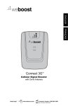
This chip is basically a computer
squeezed into a 40 -pin package
whose pinouts are detailed in Fig. 1.
The 8031 must be told what to do. In
the case of the Call Restrictor, the
8031 must monitor the telephone line
to detect dialing. If the number being
dialed starts with 1900, 976 or 0, the
8031 must immediately disconnect
the telephone line for about 2 seconds and then reconnect it again to
wait for the next dialing sequence.
The sequence of required events are
permanently stored in an EPROM.
Upon power -up, the EPROM program is read into a 6264 memory
chip. Once this program is read, the
8031 executes each step in the required sequence. Once the restricted
numbers are sensed, the program
tells the 8031 to deenergize a relay
whose contacts are in series with the
telephone line.
PORTI (1.0)
PORT' (1.1)
PORTI (1.2)
PORTI (1.3)
PORTI (1.4)
PORTI (1.5)
PORTI (1.6)
PORTI (1.7)
RESET
SERIAL IN
SERIAL OUT
INTERRUPT O
INTERRUPT 1
TIMER/COUNTER 0
TIMER /COUNTER 1
WRITE
READ
CRYSTAL 1
CRYSTAL 2
GROUND
The Call Restrictor makes use of an
inexpensive 8031 controller chip.
18
/
MODERN ELECTRONICS
/
March 1991
When the contacts of the relay are
open, the relay acts much like a telephone hookswitch. It electrically removes the telephone instrument
from across the line, simulating putting the handset back in its cradle.
After the 2- second off period has
timed out, the 8031 re- energizes the
relay. This action closes the contacts
and re- establishes connection of the
instrument to the phone line. At this
time, a dialtone is once again restored. At the conclusion of these
predetermined events, the 8031 rearms itself.
The Call Restrictor is designed to
be placed on a line that uses only
tone -dial -type instruments. The 8031
responds to the dual -tone multi-frequency, abbreviated DTMF (see
Dual -Tone Multi- Frequency box
elsewhere in this article) signals generated when a number is punched in-
40
2
3
4
11='
l?
r
5
NM
MO
6
7
111
8
9
10
12 ism
13
IMO
14
15
16
14
18
19
20
ADDRESS /DATA
ADDRESS /DATA
ADDRESS /DATA
ADDRESS /DATA
ADDRESS /DATA
ADDRESS /DATA
ADDRESS /DATA
32 ADDRESS /DATA
31
11
30
29
28
27
27
NM
Vdd
39
38
37
36
35
34
33
El
25
24
23
22
IP
21
0
1
2
3
4
5
6
7
+ 5V
ADDRESS LATCH ENABLE
PROGRAM STORE ENABLE
ADDRESS 15
ADDRESS 14
ADDRESS 13
ADDRESS 12
ADDRESS II
ADDRESS 10
ADDRESS 9
ADDRESS 8
Fig. 1. Pinouts for the 8031 microcontroller used in this project.
Say You Saw It In Modern Electronics
A Shocking Offer!
Now for the first time in CIE's 56 year history you do
not have to be enrolled at CIE to receive our introductory Electronic and Electricity Lesson Modules.
Available for a limited time to non -students for the
shockingly low price of only $99.50.
With CIE's patented AUTO -PROGRAMMED
method of learning you'll quickly learn and then
master the basics of electronics and electricity and
then move on to... DC/AC circuit
theories, fundamentals of bi -polar
junction transistors (BJT), field
effect transistors (FET),
wiring, diagram and schematic readings, component
identification, soldering
techniques... and much,
much, more.
Your commitment to CIE
ends with your payment, but
CIE's commitment to your
success just begins when you
receive your
39 lessons, exams, binders and equipment. This
special introductory price includes all the benefits and
assistance CIE normally extends to its students and
graduates. You'll be entitled to unlimited access to
CIE's faculty and staff to assist you in your studies via
a toll free 800 number six days a week, 24 -hour
turnaround on grading your submitted exams, CIE
Bookstore privileges, a patented learning method,
reference library, a student, faculty
and alumni electronic
bulletin board and a free
issue of CIE's school
newspaper The Electron.
All this knowledge and
support will put you on the
road to understanding
digital electronics,
microprocessing principles,
computer systems, telecommunications, and
much, much,
more.
All This and Much More
For ONLY!
Free Issue of The Electron
Build your personal burglar alarm
Instructors available 6 days a week
20 lesson books containing 39
theory and hands-on training
lessons and exams.
Bookstore Privileges
Patented Learning Method
Electronic Bulletin Board
24 -Hour Grading
Yes, send me CIE's 39 Introductory Electronic
and Electricity Lessons and Equipment.
Name:
Address:
City:
Apt. #:
State:
Age:
(-í1
Total Merchandise
Ohio Residents add 7% Sales Tax:
California Residents add 6 -1/2% Sales Tax
Total this order:
Method of Payment: Amount Enclosed
Personal Check or Money Order
r7 Master Card -I Visa
n II Ii
Zip:
Phone
rf
$
II
II II n
Card Expiration Date'
BOOKSTORE
1776
1:6)crinnd.
I
Tilt
Signature
`irrri
11166 1-111)1
CHARGE BY PHONE!
12161 781-9400
BK01
$149.50
9
-.
AM to 4:30 PM Eastern Time; from Ohio 1- 800 -523 -9109
from all other states 1- 800 -321 -2155
.i
N
.d
CD
1
l
A
RP
d
m
.1
N
A
M
W
CO
A
.l
A
to the instrument's keypad. By detecting and acting upon these tones,
the 8031 is capable of tapping into
the line via an output signal sent to
the relay circuitry.
The G8870 receiver chip in the Call
Restrictor is a very complicated device. Older DTMF receivers required
large, bulky audio filters. The G8870,
on the other hand, incorporates all
the needed filtering inside an 18 -pin
IC. Unlike other receivers of this
type, the G8870 does not need additional circuitry that would allow it to
be connected directly across the telephone line.
On -board the G8870 is an operational amplifier that can be wired as a
differential amplifier. Details for the
internal circuitry, pinouts and pin
functions of this chip are shown in
Fig. 2. Note that the telephone line
wires across pins 1 (IN +) and 2 (IN -)
through a series of resistors and capacitors that are wired to form the
differential -amplifier arrangement.
Internal circuitry of the G8870 divides the input dialing tones into
their high and low groups, processes
them and converts them into the binary table shown in the box.
Note that the G8870 chip requires
a 3.58 -MHz crystal for operation,
while the 8031 requires a crystal that
is three times higher in frequency.
O
H
W
CO
0
X
F
N
1
A
4.) N
H -1
1
About the Circuit
The Call Restrictor is a fairly complex electronic device. Because of
this, the overall schematic diagram is
broken into five sections, as shown in
Fig. 3 (A) through (E). Section (A) illustrates the wiring required for 8031
controller IC1, 8K memory 1C3 and
3 -to -8 -line decoder 1C4 that is used to
enable 1C3, EPROM 105 in section
(B), and DTMF receiver chip 106 in
section (C).
Also shown in Fig. 3(C) is the transistor- driven relay (R YI) that interrupts and restores the telephone-line
connection. Figure 3(D) shows the
wiring for a second relay, R Y2, used
20
/
MODERN ELECTRONICS
/ March 1991
w
Z
M
Z
M
N
0
F
O
Z
Say You Saw It In Modern Electronics
Pin Functions for the G8870 DTMF Receiver /Decoder Chip
Pin
1
Name
Function
IN+
Noninverting Input
Inverting Input
Gain Select -provides access to output of front -end differential
amplifier for connection of feedback resistor
Reference Voltage (nominally Vdd /2) -can be used to bias inputs
-
3
IN
GS
4
Vref
5
7
IC
IC
OSC1
8
OSC2
9
Vss
2
to mid-rail
6
10
TOE
11
DO
12
D1
13
14
D2
D3
15
StD
16
ESt
17
St/GT
18
Vdd
Internal Connection
Internal Connection
Clock Input- 3.58 -MHz crystal connects between pins 7 and 8
completes internal oscillator
Clock Output -see pin 7 above
Negative power- supply voltage (normally grounded)
Three -state Output Enable Input -logic high enables outputs DO
through D3; internal pull -up provided on -chip
Three -state Data Outputs -(with pins 12, 13, 14) when enabled by
TOE, provide code corresponding to last tone
See pin 11 above
See pin 11 above
See pin 11 above
Delayed Steering Output -presents logic when received tone pair
has been registered and output latch is updated; returns to logic 0
when voltage on St /GT falls to less than Vtst
Early Steering Output -presents logic 1 immediately when digit
algorithm detects recognizable tone pair; any momentary loss of
signal causes ESt to return to logic 0
Bidirectional Steering Input /Output Time Output -voltage greater than
detected at St causes device to register detected tone
pair and update output latch; voltage less than
frees device to
accept new tone pair; GT output resets external steering time constant, its state a function of ESt and voltage on St
Positive power connection
1
Fig. 2. Details for G8870DTMFreceiverchipusedinthisproject: (A) Block diagram of internal circuitry and (B) pin functions.
in the Call Restrictor. By placing
R Y2, a line -sense relay, in series with
both the red- and green -insulated telephone -line conductors, the 8031 can
intelligently detect whether or not the
handset of the telephone instrument
is on -hook. This is accomplished by
monitoring pin 2 of ICI for the presence of a ground voltage.
Figure 3(E) shows the circuit details for the ac- operated power supply for the project. This is a classic
full -wave bridge- rectifier arrangement with capacitive filtering and
regulation to a tight + 5 volts via IC8.
When the Call Restrictor is in operation, the internal oscillator of IC)
runs at 11.059200 MHz, the frequency controlled by crystal XTALI. By
making use of address lines AO through
Say You Saw It In Modern Electronics
ICI can grab needed information anywhere within a range of
8,000 bits; hence, the use of 6264 -15
RAM chip IC3 in the section (A) circuitry. Although the full 8K memory
locations are not used in the Call Restrictor, cost of the 6264 RAM chip is
so low that no other smaller RAM
need be considered.
Address lines A13, A14 and A15 are
decoded into chip- enabling ground
pulses with the aid of IC4. Binary
codes generated by ICI at pins 26, 27
and 28 are converted into single
ground control signals. By applying
grounding pulses at the appropriate
times with a running program, any
one of eight peripheral chips can be
activated simply by calling its special
address. Without enabling pulses to
Al2,
turn on the various chips, data conflicts would occur, due to the fact
that all peripheral chips are wired in
parallel to the common eight -bit data
bus to which pins 32 through 39 of
ICI connect.
The Call Restrictor requires three
enabling pulses. The first, at address
0 hex (OH), is used to enable program
device IC5. With every ground pulse,
ICI reads the program information
from IC5. The second address is at
0E000 hex (0E000H), where the same
grounding pulses are used to enable
IC6 every time you want this chip to
sense the DTMF tones across the
line. Because IC6 requires a positive
voltage to enable its output, one
stage of hex inverter IC7 is used to
convert the ground pulses from IC4
into the positive pulses needed by IC6.
The final address, at 8000 hex
(8000H), uses the ground pulses to
enable memory chip IC3. Along with
the proper read and write ground
pulses, IC4 allows ICI to place information in and extract data from
memory chip IC3.
Also required is the data bus over
which eight -bit words are read from
or written to memory. This also includes reading of program material
from IC5. Intel uses the multiplexing
technique to use pins 32 through 39
of ICI for both the low -order address
bus and eight -bit data bus.
To extract the required address or
data information at the correct time,
octal D -type latch IC2 is used. Here,
pulses from -ALE pin 30 of ICI is
used to "pulse" IC2. Pulsing allows
the low -order address information to
pass through on pins 2, 5, 6, 9, 12, 15,
16 and 19 of IC2 while data information is stopped. Along with the enabling pulses from IC4 and the read
or write signal from ICI, separate address and data bus information is delivered to their appropriate chips at
the proper times.
Examining sections (A) and (B) of
Fig. 3, you can readily see that all address and data lines are wired in parallel with IC3. If not for the enabling
March 1991
/
MODERN ELECTRONICS
/
21
4
+5V
48
Port 1.8
_
----
1
28
2
27
3
26
4
25
5
24
6
23
7
22
8
21
A15
A14
1-To IC4
A13
2
All
23
A18
21
A9
24
A8
25
19
IC1
18
8831
18
17
IC3
6264 -15
16
__J21
MOM
)(TALI
28
26
Al2
15
B
13
19
12
11
T
C1
C2
32
B
3Opf B
33
34
0
0-
35
36
31
3?
7
38
39
29
PSEN
38
AD?
AD6
AD5
AM
19
17
16
14
15
1C2
12
74LS373
9
13
AD3
8
AD2
AD1
18
a
ADO
ALE
7
6
4
5
3
2
A?
A6
le
A4
A3
A2
Al
AO
,
1
8
9
18
+5V
1
C4
,luf
Reset
14
28
-
4
A5
28
11
3
17
2?
16
22
28
+ 2.2uf
C3
1C4
74LS138
+
+5V
A15
Froh IC1
Addr 8888H
A14
A13
11
1
Addr
OR
II
15
Addr, 8E89911
To IC5
Pin
Il To IC7 Pin
28
1
5
Fig. 3. Complete schematic diagram
of Call Restrictor is shown here in
five parts, labeled (A) through (E).
16
6
+5U
Fig. 3(A)
22
/ MODERN ELECTRONICS / March
1991
Say You Saw It In Modern Electronics
+5V
4
T
Rl-R8
1
lOR x 8
s
To
To
IC3
Pin
Pin
Pin
Pin
Pin
Pin
Pin
Pin
11
12
13
15
16
17
18
19
Pin
Pin
Pin
Pin
Pin
Pin
Pin
Pin
Pin
Pin
Pin
Pin
Pin
2
27
ADO
ADl
AD2
AD3
AM
AD5
AD6
AD7
All
All
23
AIO
21
24
A9
25
A8
A7
3
A6
4
28
11
12
13
15
16
17
18
19
14
IC5
2
23
21
24
25
Programed
2764
1
3
4
AS
5
A4
6
A3
7
A2
8
7
8
Al
9
AO
18
IC4 Pin 15
the output from 106 only when pin
10 of IC6 is high.
The 8031 has eight specially adaptable pins identified as PORT1 at pins
through 8 of IC1. Using this port,
through program control, information can be read from and written to
these pins. Operation is like the case
with the data bus but with an exception: no enabling pulses are needed to
turn on any specific chips.
By telling ICI to output a decimal
number between 0 and 255, you can
place any combination of Os and 1s
on the port pins. Also, under program control, the 8031 can be directed to read the binary code applied
to these pins. Note that STROBE pin
10 of 106 is connected to PORT1 pin
(PORT1.1). In the Call Restrictor, the
program in IC5 tells IC1 that a valid
tone has been detected by IC6 only
when pin 1 of ICl is at logic 1. In contrast, if pin 1 of IC1 is at logic 0, the
8031 refuses to acknowledge as usable information the binary data on
the data bus.
Another section of the project that
uses PORTI is the base circuit of Ql.
On initial start -up, pin 3 of 1C3 is at
logic 1, This voltage is applied to the
base of QI through R15. At this time,
RYI is energized and its contacts are
closed. These now -closed contacts
can be used as a telephone hook switch. By wiring the contacts in series with the red -insulated telephone line conductor, as shown in Fig.
3(D), any telephone instrument connected to the line is under control of
ICI -not the caller.
If ICI senses that 1900, 976 or 0 are
the first digits dialed when a call is being placed, the EPROM program instructs the 8031 to ground pin 3. This
cuts off Q1 and deenergizes RYI.
When the relay contacts open, the
telephone -line connection is automatically broken. After 2 seconds,
IC1 re- applies a logic 1 to pin 3 to reactivate the relay and restore dialtone.
Any number dialed to make an
outgoing call that the project will
permit is stored in memory in the Call
Addr
ON
YO
18
28
22
To
Fig. 3(B)
ICI Pin 29
PSEN
pulses created by IC4, data and address conflicts would occur between
IC4 and 105. Pull -up resistors RI
through R8 in Fig 3(B) apply a constant + 5 volts to the eight address/
data lines.
Section (C) of Fig. 3 shows the interfacing required for the Call Restrictor. Points C and D connect directly across the incoming telephone
line, as shown in section (D). Because
of the characteristics of the differential amplifier at pins 1 and 2 of IC6,
the direct connection between the
two causes no ill effects to the telephone line. The differential amplifier
also provides the FCC -mandated
line -to- equipment isolation.
Note that 106 wires across the tele-
Say You Saw It In Modern Electronics
phone line through Cl, C2, R9 and
R10. Only tones generated by the telephone instrument are permitted to
enter 106. After processing by internal filters and converters, 106 outputs at DO through D3 pins 11 through
14 the binary equivalent of the input
tones. This is the data ICI reads and
acts upon when the need arises.
Because of the way 106 is wired,
data information is always at the data output of this chip, even when no
button on the keypad of the telephone instrument is pressed. To surmount this, 106 is equipped with a
STROBE line at pin 10, which is at logic 1 only when a valid tone pair are introduced at the input of this chip.
Hence, ICI is programmed to accept
March 1991
/
MODERN ELECTRONICS
/
23
Restrictor. When you hang up, a
means must be found to have IC1
erase the current number before you
can dial another number to avoid
conflict. This is accomplished by Tel tone line-sense relay RY2 shown in
Fig. 3(D) whose internal contacts
close every time a telephone instrument is lifted off-hook.
By connecting one side of RY2 to
ground and the other side to PORTI
pin 2 of IC1, the 8031 can act upon
the hang -up signal. If PORTI senses a
ground condition at pin 2, IC1 is instructed to erase the current number
from memory.
Operation of RY2 is straightforward. This relay senses the current
flow when the contacts of RY1 are
closed and the handset of the telephone instrument is taken off-hook.
When both sets of contacts are closed,
a conductive path is created for the
dc voltage coming from the telephone line to flow. This causes RY2
to energize and close its contacts just
before a new number is dialed.
The Call Restrictor requires a
5 -volt, 100 -mA dc supply for operation. Circuit details for an ac -operated supply that meets these requirements are shown in Fig. 3(E). The
power transformer for this supply
circuit should be a plug -in wall -type
unit to provide isolation between the
117 -volt ac line and low- voltage circuits in the Call Restrictor.
In operation, the low-voltage ac
output from the secondary side of T1
is rectified to pulsating dc by the
bridge rectifier made up of Dl through
D4. The pulsating dc is then filtered
to pure dc by C8, after which it is regulated to + 5 volts by 1C8 and further
filtered by C9 for delivery to the remaining circuits in the Call Restrictor.
+5V
To
Point
C
To
Point
D
-
C5
R9
.81
188K
L1
.1
18
R-LNAAR
.81
R14
188E
T
T
R11
R12
471(
471(
B
228E
R13
IC6
G8878
1'''1(
14
13
B
4
12
11
D3
Pin
Pin
1C1 Pin
IC1 Pin
To IC1
D2
To IC1
Dl
To
D8
To
6
15
9
18
Strobe
To IC1
Pin
1
Enable
7
8
XTAL2
+5V
14
To 1C4
Pin
4
7
IC7
4869
+5V
s-----
To
Point
A
To
Point
B
DISCONNECT
QI
To IC1
Pin
RELAY
2N2222
3
Point
RY2
Line Sense
To RY1
Relay Contacts
C
Red
Red
4
A
Telephone
Line
B
To
Restricted
Telephones
(J2)
(J1)
As you can see from the multiple-section schematic diagram in Fig. 3, this
is a fairly complex project. However,
bear in mind that a lot of the circuitry
shown represents repetitious wiring.
/
36
37
38
39
5
Construction
MODERN ELECTRONICS
R-
L
16
L
R18
-
/
R
L
17
R L
C6
To
24
C?
March 1991
Cre
Green
v
Point
To IC1
Pin
2
Say You Saw It In Modern Electronics
D
DltoD4
1N4001
I
A
K
D1
A
K
D2
I C8
+
IN
OUT
1 +5V
7805
117VAC
A
K
TD4
D3
K
Ti
CND
A
--e--
C9
C8
330uf
330uf
Nall
e
C10
,1
Transformer
GND
Fig. 3(E)
PARTS LIST
Semiconductors
D1 thru D4- 1N4001 silicon rectifier
diode
ICI -8031 microcontroller
IC2- 74LS373 octal D -type latch
IC3- 6264 -15 SRAM memory
IC4- 74LS138 3 -to -8 -line decoder
IC5- Programmed 2764 EPROM (see
Note below)
IC6 -G8870 DTMF decoder (see Note
below)
IC7- CD4066 hex inverter
IC8 -7805 fixed + 5-volt regulator
Q1- 2N2222 or similar general purpose silicon transistor
Capacitors
C1,C2 -30 -pF ceramic disc
XTAL2- 3.58 -MHz crystal
Perforated board with holes on 0.1inch centers and suitable Wire Wrap
or soldering hardware (see text);
sockets for all DIP ICs; suitable enclosure; machine hardware; hookup
wire; solder; etc.
Note: The following items are available from
Suncoast Technologies, P.O. Box 5835,
Spring Hill, FL 34606: G8870, $10; Tel tone line -sense relay, $5.75; programmed
2764 EPROM, $7; six -conductor telephone cord, $1.25; 11.059200-MHz crystal, $1.75. Add $2.50 ($3.50 in Canada)
S &H per order. Florida residents, please
add 63/4 state sales tax.
C3- 2.2 -µF, 16 -volt electrolytic
C4,C7,C10-0.1 -µF ceramic disc
C5,C6-0.01 -µF ceramic disc
C8,C9- 330-µF, 16 -volt electrolytic
Resistors (`/, -watt, 10% tolerance)
R1 thru R8,R15- 10,000 ohms
R9,R10,R13- 100,000 ohms
R11,R12-47,000 ohms
R 14- 220,000 ohms
Miscellaneous
RY1 -5 -volt dc spst reed relay
RY2- Teltone line -sense relay (see
Note below)
T1- 12.6 -volt, 150-mA plug -in wall type transformer
XTAL 1- 11.059200 -MHz crystal
Say You Saw It In Modern Electronics
PARTS SUPPLIERS
B.G. Micro
P.O. Box 28209
Dallas, TX 75228
214-271 -5546
Digi -Key Corp.
701 Brooks Ave. S.
Thief River Falls, MN 56701 -0677
-800- 344 -4539
1
JDR Microdevices
2233 Branham Lane
San Jose, CA 95124
1- 800 -538 -5001
If you have any experience at all in
building circuits, you should fairly
easily build the Call Restrictor.
You can mount the components on
perforated board that has holes on
0.1 -inch centers, preferably with
copper rings around each hole, and
point -to -point wire them together
with Wire Wrap or soldered connections. Your first step is to photocopy
the schematic diagram sections so
that you can strike off each wire run
as you make it according to the Master Wiring List.
Begin construction by mounting
the sockets for the various DIP ICs
on the circuit board. If copper rings
surround the holes on your board,
solder only the four end pins into
place. Use solder sparingly to avoid
getting it on all but about % inch of
the pin lengths. If your board does
not have copper rings around each
hole and the socket pins do not provide a friction fit, bend the four end
pins slightly outward to hold each
socket mechanically in place. Do not
plug the ICs into the sockets until after preliminary voltage checks have
been made and you are satisfied that
your wiring is correct.
After mounting the IC sockets,
mount the various components on
the board. If you are using the Wire
Wrap technique to wire the circuit,
use Wire Wrap posts to hold these
components (except the relays, which
mount via their own pins) in place,
soldering the component leads to the
posts on the top of the board.
Once the components are in place,
refer to the Master Wiring List and
begin with the ICI socket to make
your interconnections. As you make
each wire run, trace its path on your
photocopy of the schematic in a contrasting pencil or pen color. As you
go, properly polarize your connections to the socket pins, electrolytic
capacitors, relays and diodes.
Make sure your connections to the
pins of Q1 and 1C2 are correct. Note
that the latter is the only IC that
should be mounted on the board at
(Continued on page 71)
March 1991
/
MODERN ELECTRONICS
/
25
Project
The Modern Electronics
Computer Experimenter Lab
(Part 3)
Adding a combination Digital Signal Generator and
8088-microprocessor Computer Experimenter Platform
to the Dual- Channel Function Generator
By Martin Meyer
month, we gave details
for building and using an analog Dual -Channel Function
Generator that had room on its pc
board for adding a digital signal generator, which is the subject of this installment. This add -on is a continuation of a series begun in the January
issue with a build -it- yourself low cost Digital Storage Oscilloscope and
optional eight -channel Logic Analyzer module.
This month's Digital Signal Generator add-on generates up to 23 simultaneous digital signal trains that will
be used as signal inputs for upcoming
digital experiments. A main feature
of this project is that you will be able
to start learning about programming
the 8088 -series microprocessor. A
limited understanding of programming, though not necessary for these
projects, will allow you to integrate
digital parts that require software interfacing into your projects.
An 8088 microprocessor in the
Digital Signal Generator comes supplies all the necessary bus signals,
permitting the instrument to also be
used as a platform to build, test and
learn about peripherals and programming of the most popular series
of microprocessors ever introduced.
In future articles, we will present
Last
26
/
MODERN ELECTRONICS
/ March
:
N,yNtwu
«,r
1171.1,
.,w
3,
GENF RAfOR
(
projects using the 8088 microprocessor in this project as the base processor. Figure 1 gives an overview on
how the various experimenter Labs
could be configured.
Next month, we will describe a
Prototyping station that connects the
equipment together and begin our
1991
DIGITAL /ANALOG FUNCTION GENERATOR
tt
I. It i:xl1.:1121s11 . t It 1. NM",
discussion on theory, applications
and experiments of interesting analog, digital and computer circuits.
System Overview
The Digital Signal Generator serves
as the stimulus that allows you to ex-
Say You Saw It In Modern Electronics
amine experiments that involve digital circuits. You wire the circuits to
be explored on a solderless breadboard or a Wire Wrap prototyping
board, depending on personal preference and complexity and use the
Oscilloscope or Logic Analyzer to
observe both inputs and outputs.
The advantage of using a Logic
Analyzer when working on digital
circuits is that you can observe both
inputs and outputs simultaneously.
If you were to study the operation of
a 74LS165 shift register, for example, you would find that you need
eight data signals, a signal to load the
data into the register and a clock to
shift the data out of the registers. The
Digital Signal Generator described
here produces the needed signals,
while the Oscilloscope lets you observe inputs and outputs.
Computer circuits like analog-todigital (A /D) and digital -to-analog
(D /A) converters, input and output
ports, memory, ROMs, interrupt
systems, displays and digital signal
processors (DSPs) can be studied using the 8088 test platform included in
this project. For example, A/D and
D/A converters, wired on the Wire
Wrap prototyping board, can be connected to the I/O ports. An analog
signal, supplied by the Function Generator, connects to the ANALOG input.
The processor program can invert,
filter and limit the range or simply
turn the data around and out to the
D/A circuit. You monitor circuit responses and actions using the analog
and logic analyzer features included
in the Digital Storage Scope.
Analog circuits like operational
and power amplifiers, comparators,
filters, sensors and power-control
circuits can be wired on the prototyping station and evaluated using the
Function Generator and the Digital
Storage Scope. You can use the pro totyping station to build hundreds of
useful circuits that illustrate basic ac
and dc circuit principles, magnetic
and transformer principles, power
supply operation, and to demon-
Say You Saw It In Modern Electronics
DIGITAL SIGNAL
AND FUNCTION
GENERATOR
PROTOTYPING
STATION
DIGITAL STORAGE
SCOPE AND LOGIC
ANALYZER
WL
DIGITAL
CIRCUIT
EXPERIMENT
D
Ñ
Ì
40 PIN CABLE
LOGIC AND
ANALOG PROBES
Ì
Ñ
A
L
L
5
I
LN
GLS
23 DIGITAL
SIGNALS
/
DIGITAL CIRCUITS LAB
DIGITAL SIGNAL
AND FUNCTION
ÇENERAT ÇR
PROTOTYPING
STATION
DIGITAL STORAGE
SCOPE AND LOGIC
ANALYZER
COMPUTER
EXPERIMENT
40 PIN CABLE
088 BUS
D
S
A
5
SIGNALS G
G
N
A
S
A
L
G
I
40 PIN CABLE
LOGIC AND
ANALOG PROBES
T
A
N
GLS
23 DIGITAL
SIGNALS
/
8088 COMPUTER CIRCUITS LAB
DIGITAL SIGNAL
AND FUNCTION
GENERATOR
PROTOTYPING
STATION
DIGITAL STORAGE
SCOPE AND LOGIC
ANALYZER
ANALOG
CIRCUIT
EXPERIMENT
-1/1/1/-
G
I
T
A
L
ANALOG PROBES
A \ALOG
G
N
A
L
S
CIRCUITS LAB
R
L
G
N
GLS
/
Fig. 1. Overview of how various Experimenter Labs can be configured.
strate how games, voice, video and
ultrasonic circuits work, to name just
a few of the may things you can do
with this system.
The Digital Signal Generator/8088
Computer Experimenter Platform is
built on the same circuit -board assembly you used to build last
month's Dual Function Generator.
This keeps the cost to less than $140
for the combination Dual Function
Generator /Digital Signal Generator/
8088 Computer Experimenter Platform system.
Circuit Description
To generate the digital signal trains in
the Digital Signal Generator add -on,
an 8088 microprocessor, 8K of
RAM, 8K of ROM, an 8155 I/O
port /timer and the required support
circuits are used. The circuitry for all
this is shown schematically in Fig.
2(A) and Fig. 2(B). With this arrangement, digital signal trains are
generated by toggling the U13 output
port signals. The timer can be programmed to produce a variety of
March 1991
/
MODERN ELECTRONICS
/
27
//a//w
0RJ
OZ
ow
NOÓIaVVV
VV
VVO..V
X
X
N..001
r
m
04NN
J
M1
á
\\\\\\\
o-.NOnPUI+-
aaaaaa
Im
PJM1
a
,71.7
aa
a aá a
a
ti
V
a
á
P
o
NII.O
0ÿ
rr-=4q
O-.NMPNWM1
7
O-.NMPIP.OM1
O-.NMPI(N.OM1
00000000
00000000
00000000
\\\\\\
U1
IM11
V
O-.NMPNNM1 V
00000000 OU
O-.NMPN.OM1
V
O-.NMPIP0M1
V
p
00000000 OV ¡.
00000000 ou
PM1
M1
O-.NMN IIN10
000000
a«aaaaa
m
-+NMN.Or
aá
a
á
«
O-.NMPN.Or
00000000
O-.NMP
O-.NMPN.OM101N-.-.-.-.-.
aaaaaaaaaaaaa««
M1I
N
ON
>
o
m
o
aaaaa«aaaaaa.a
//////// // /
N
O-A.4
OjY O
M VV>
a--
O-.NMPN.ONmMO-.NMRNMCNW O
NNNN
OOOOOOOOaa
aaaaaa\\\\
««aaaaaa ......
ymÿ
N
N
ZILLIL
w\\
Or0
O
IOIaWa
PN.O
OAO ¡nano
10:12JH
aaaaaaa
«Z
O..
M
-.NMNN
««CECE
MM
O-.NMPNIOM1
}
O
z
E
r
CO
W a
crin r
WJW z
EVE
.-
OJMN
JOSW
IIZH
..
00000000
m
O
O-.N
m
O-.NMPN.OM1m01-.-.-.
J a««aa«aa«a«aa
M
m
m M1 'N N
N
N
~NNJIW
30
P
>
N
Y
J
V
a
)-Y.
OJW
aVN
w
a
w
K
28
1
CO
aaaaa a a a a CC
I
V
N
O
-.N-.N
N
X
O-.NMP
N
VV
ZZ
) }ZZ M
w
OOWWIiNVI\
mrc««WV¢1A.
/ / / // / ///
N
W
K
/ MODERN ELECTRONICS / March
1991
Say You Saw It In Modern Electronics
N
5
/
O
W
Q
O
O
O
-4,
NL:
O
410Q0.Oh000,NMPN,DNOOIO-+NMQIfN10
aD_ao_aD.O.D.D.aD_0.ao_mao_D_aO,ArOOVVN4
40 0000000000
?
1
O
a
4lL W
1
w
-NMPNOM1mO,O-NMPNONmO,O-NMPNNNmO,O-NMPNtO
tat=
N N NN N
a
0000
O
NNNNOO
O-iNMPNIDM1O-+N111.IINNM1O,NMPNE\Z
aaaaaaaammmmmmmmVVVVVVHrWNVINNN-4-+,,ZZ
4
4
O,N1IPNIOM1OO)
EOJOttOV W 000000000-+NMPNNN0J0),-i-+-+-1.-,-1-+.
MZSal+3rc0.tt44aaaaaaa¢aaaaaaaa¢¢a¢aaaaóa
O
CO
xx
WM OP
/
/0 E
YW
JW\//JViM1IDNQMN,0
00,0-+NMPN,O
NNMMMMMMM
V
NNNMMMMMMM
a
Z
N
O
0
O
N
N
4
MN
O
0 0
00
O
CO
0 0
O
0 M1
m
Q
CO
0
O
0 0
O
O
N M1 P
IP
0
O
o
N
ó
O
ry
P
?
Z
81
Ñ
III
m
N
z,11>
M1
M
P
N
o o
m°
3
INE
a
V
MOVi
.....
.....
.....
N
N
NN
á
.......MO
.......EM
.......EM
m
O10
NMI
NMI
M
1010
NN
O,NMP1PIO1,
O-+NMPIINN1,
O-4NMPN
0.0.0.0_1maa
aaaaD_aaa
0.110.0.0..11
>WV 00 )VD! 0'0_ NN
OXX XX OX0 N.
1-0.
a¢\ 00 V2
aaaaaaaa 00000000 VVVVVV
E
IJ
WJR00
ti00000000
aa¢aaaaa I,a131W.,
W
,
NM
NNM1OQ
O-,om
HO
..
x
P
M
>
N
O-+NMPNWM1
00000/000
CO
M1
M1
x
0
O -MNIP
NN
ID'1,6
A
A,
/0
J
zi
O-INMPOWM1
00000000
aaaaaaaa
Fig. 2. Complete schematic diagram, minus dc power supply,
Say You Saw It In Modern Electronics
for Digital Signal Generator add -on.
March 1991
/
MODERN ELECTRONICS
/
31
PARTS LIST
nents (mount on last month's Dual Channel Function Generator pc
board), $69.95 + P&H;
Optional + 5- and ± 12 -volt power
supply kit (one required for both
Generators), $34.95 + $4 P&H;
Optional black steel cabinet (for
combination Function /Digital Signal Generator), $37.50 + $4.50 P&H.
Also Available from Netronics R&D
Ltd.:
For Digital Storage Oscilloscope
Semiconductors
U3,U4,U5- 74HC373
U6- 74HC04
U7-74HC139
U8 -27C64
U9 -6264
U10-8284A
U11-80088
U12-82C51
U13-81055H
D1,D2,D3- IN4002 diode
Y1 -6.144 crystal
Capacitors
C19 thru C26-0.1 -µF monolithic
C18,C28,C29,C30-22 -µF, 16-volt radial
Resistors (h -watt, 5'o tolerance)
R25,R26 -510 ohms
R27- 10,000 ohms
R28,R29-1,000 ohms
RS 1- Five -resistor 10,000 -ohm resistor SIP
RS2,RS3- Nine -resistor 10,000-ohm
SIP
Miscellaneous
S1 -Spst normally -open momentary action switch
S2- Seven -position DIP switch
J9- Three -position single in -line header
J10-Power connector
J11-five-position single in -line header
J 12,J 13 -40 -pin socket strip
P1 -DP -25 connector
Printed-circuit board; suitable cabinet (see Note below); etc.
Note: The following items are available
from Netronics R &D Ltd., 333 Litchfield Rd., New Milford, CT 06776
lyzer, $59.95 + $3 P &H;
Optional + 5- and ± 12 -volt power
supply kit, $34.95 + $4 P&H;
Optional IC socket kit (contains 33
sockets), $9.50 + $1 P &H;
Optional 100 -MHz scope probe with
10:1 attenuator, $27.50 + $3.50
P &H.
For Dual-Channel Function Generator (February 1991):
Complete set of electronic components, including pc board but not
power supply or cabinet, $69.95 + $4
P &H;
Optional + 5- and ± 12 -volt power
supply kit (one required for both
Generators), $34.95 + $4 P&H;
Optional black steel cabinet (one re-
quired for combination Function/
Digital Signal Generator), $37.50
(tel. 203-355-2659)*:
+ $4.50 P &H.
For Digital Signal Generator:
Complete set of electronic compo-
*MasterCard and VISA accepted on
all orders.
pulses and square -wave trains.
Programs to produce the signal
trains can be written on and downloaded from an IBM PC or compatible computer, or they can be run
from fixed programs stored in ROM.
The programming mode is selected
via DIP switch S2. Simple user programs can be written using the Debug
program supplied with DOS. No programming experience is needed for
writing these simple programs.
32
(January 1991):
Complete set of electronic components, including pc board but not
cabinet, power supply or probes,
$199.95 + $6.50 P&H;
Optional eight- channel Logic Ana-
/
MODERN ELECTRONICS
/
The Microprocessor. The 8088
CPU (Ull) is a member of a family
of devices that have become the
world's most popular series of microprocessors. If you are going to study
any microprocessor, this Lab series is
an excellent place to start. Basic system architecture and the instruction
set is compatible with all newer processors, except for memory width,
address size and added instructions.
The 8088 microprocessor used in
March 1991
this project is set to operate in minimum mode. That is, special control
and status signals that are necessary
for large systems are not used here.
The 8088 CPU is a relatively straightforward hardware device. Address/
Data bus lines AO through A7 are
multiplexed so that they share this
function with the eight -bit data bus
without creating conflicts or collisions. Address pins PA16 through
PA19 are also multiplexed with various
status signals.
In both cases, the address information is presented on the output pins
of the 8088 during the first part of
each machine cycle and is latched into U4 through U6 when the CPU issues an ALE (Address Latch Enable)
signal. During the remainder of the
machine cycle time, the low -order
address pins become the eight -bit bidirectional data bus, and address
lines PA16 through PA19 become CPU
status pins.
All 19 address bits are latched and
are connected to the 8088 Platform
bus. The bus includes all address, data and CPU control signals that are
used as part of the 8088 Computer
Experimenter Platform.
Clock Generator. The 8088 requires the use of 8284A clock generator UIO. This circuit supplies the
8088 with a special clock signal that
has a 33% duty cycle and is half the
crystal frequency. When power is
turned on or the system is reset, the
8284 generates a master reset signal
that is used to reset all peripherals
and the CPU. A symmetrical system
clock, labeled PCLK, is generated for
the 8088 system bus. The 8284 also
has provisions, via the RDY and AEN
signals, that support multi-processor
operation. These pins are not used in
this application.
Address Decoders. The 8088 can
address 1M of memory. The ROM is
positioned at the very top of memory, starting at F8000 if a 32K ROM
is used or FE000 if an 8K ROM is
used. System RAM is positioned at
Say You Saw It In Modern Electronics
d, Unique PC Products
credible Prices!
Installs on ANY laptop or desktop in seconds!
Learn to Modify ANY Software!
Connect Floppy Drives (3.5" & 5.25 ") To
Parallel Printer Port In 30 Seconds Flat!
Adding a disk drive has never been this
easy. Imagine attaching a floppy drive to your
laptop or desktop computer in under 30
seconds -even on PCs with built -in disk
controllers.
Backpack is an external floppy drive that
plugs into your parallel printer port. Your
printer plugs into the back of the Backpack
drive. There are no interface cards to install,
you never even open your computer. You can
have a single 3.5" or 5.25" drive and use it on
all the computers in your office just by
plugging it in. Backpack drives transfer
information to your computer at the same
speed as ordinary floppy drives, but install in
only seconds.
Connecting a high density 3.5 or 5.25 inch
drive to your computer can allow you to back
Powerful Disassembler
2941!
Snooper
takes
executable
program
code and
turns it
up your hard disk in
half the time.
Backpack allows
111114
you to connect
high density
drives to any
w`
computer, even older
backpack
PC and XT compatibles,
regardless which version of DOS you use.
Backpack comes in four configurations:
5.25" 360K drive, Cat. #BACP360, $299
5.25" 1.2M drive, Cat. #BACP12, $299
3.5" 1.4M/720K drive, Cat. #BACP14,
$299
3.5" 2.8M drive (also read/writes 1.4M
and 720K), Cat. #BACP28, $399
into
New Advanced Capabilities
The new Voice Master software recognizes up
to 1,024 words, each of which can activate a
different macro. Macros can include prerecorded digitized speech or sound files which
play back when activated.
A
Sound Development System
Ideal for experimenters and software
developers, you can make sound files for spoken
advisories, music/sound effects, etc. Sound files
can be played through the headset or Speech
Thing external speaker. All of the functions can
be controlled from C, BASIC, ASM.
Voice Master Key System II interfaces
with your PC through the parallel printer port
Serving Computer Users Since 1982
f5; <0015,
i5
500120 '0017c
prop
snort00ána
¡borno)
Ox
,00, 7G1
:Jump
;0071,
.00720
imp
snort 000111
;0007
pp
10
Pessn
Óx, OWORO PTA
ne
t
<
sipo)
:Dono
0072E
[bpi l5hl
00/75
es 10x]
Éx, OWORO
PTR
00717
00721
dx
I understand my purchase is
covered by Central's 30 day satisfaction
right away.
guarantee.
J
I'm not ready to order now, but please
make sure I'm on your mailing list.
input.
New software recognizes over 1,000 words!
Includes developer kit for sound editing.
Quick, simple installation.
Includes controller card, software, and
headset. Voice Master Key System II
includes headset & external Voice Master.
Order Today!
Voice Master Key Cat. # VOIM, $149.
Voice Master System II, Cat. #VOIM2,
Name:
Address:
City.
Daytime telephone:
CA Res. Specify County:
$199.
U
ZIP:
S'I':
Check/Money Order enclosed.
Charge my Visa, MC, AMEX, Discover:
Card #:
Driver's License #:
Exp:_
Signature:
Qty. Cat. #
Nee
Description
"Free Space" indicator
Subtotal
30 Day Money Back Guarantee
CA Res. Add Sales Tax
Mail To:
Central Computer Products
1.800.456.4123
(805) 524 -4189 24 Hour FAX: (805) 524 -4026
330 Central Avenue Fillmore, CA 93015
Visa MasterCard AMEX Discover
50 Shippir9. CA residents add sales ax.
l
154
aun
no patches
00710
00115
J Please rush the following products to me
Recognition- invokes macros w/ voice
CIRCLE NO.
P TR
Gil
u
P
System II also
includes an
external speaker
and text-to- speech
software.
Ar41 55
p,, MORO
p OE],
l
Price Breakthrough 512K Printer Buffer
COMPUTER PRODUCTS
Its
ousn
push
Inerease Computer Productivity!
CENTRAL
WORO PTR
ies
TOY
printer into the
Voice Master
System II box).
Waiting for a file to print can be frustrating unless
you have a printer buffer. This buffer quickly absorbs
your file so you can get back to work fast. The buffer
quietly feeds the file to your printer without slowing
down your computer! Don't wait, order today.
Holds about 360 double- spaced pages Includes
power supply so it will hold data even if your computer or printer is turned off Repeat function to print extra copies
512K Parallel Buffer, $129, Cat. #PB512PP.
roore
ex, WORO
(you can plug your
Voice
Pnnt
search
Processor: 1015A1
(NC
How To Talk To Your Computer
-
Oisuse male
File
Format Al
OR
00721
assembly
00725
00725
Iep.12n1
language
W0á0PTRes:iSa;
Dana
A
source code
0015
a;x
00ná
That's not
so unique, but Snooper is intelligent. It
automatically comments the source code and
labels jump targets. Snooper even includes a
patcher to make small changes to a program
without time-consuming reassembly. For more
extensive changes, Snooper is compatible with
Microsoft and Borland assemblers.
Snooper gives you commented source code
fur almost any DOS file-including COM,
EXE, SYS. Its pull -down menus and on -line
help make disassembly fast and easy. So
what's this good for? Well it's the best way
around to learn assembly language and to
make changes to software when you don't have
the source code. Cat. #SNPR $49. Order
today.
Let Your Voice do the Work of Tedious & Repetitive Keystrokes!
If you have trouble memorizing all those
complicated "Control- Alt-Shift -Function"
commands then Voice Master Key is just for
you. Now you can simply speak the command
"lxlld," "zoom," etc.- into Voice Master's
headset and see it done instantly.
Nero
Ad Code. I,r7.2
ON FREE. INFORMATION CARD
l
Dept. 137 -2
330 Central Avenue
Fillmore, CA 93015
S &H
Total
55.50
00000 to permit use of interrupts if
needed for Platform applications.
Lines At8 and At9 are decoded by
U7B. If A18 and At9 are high, the
ROM is selected; otherwise RAM is
addressed.
Chip U7B decodes the I/O
addresses. Provisions have been made
for four I/O devices by decoding addresses A6 and A7 when the io /M pin
28 of U// is low. I/O decoder U7B
generates chip -select lines at locations
ox, 4x, 8x and cx. The Digital Signal
Generator uses Port CX for the U13
and Port 8X for UART U12.
The 8155
I/O Port. In this project,
U13 plays a key role. The 8155 device
consists of two eight -bit and one six -
bit I/O ports that can be configured
to be either inputs or outputs. The
six -bit port can be programmed to be
status pins, the eight -bit ports operate in a handshaking mode.
Also included is a 14 -bit timer/
counter that provides either a square
wave or terminal count pulse outputs. The six -bit port is used as an input port to read the program selector. If the download mode is selected, the six -bit port is available to produce digital signals or to act as an I/O
port. The program toggles the ports
to produce the digital signal trains.
The programs simply initialize the
8155 to configure the ports and timer
operation. Outputs are then set to the
value desired at the beginning of the
digital signal train. The system loops
until the next change is required, at
which time, the ports are changed.
This process is duplicated, changing
the loop time and the output data to
produce the desired signal train.
The counter /timer can also be used
to produce digital signals. In square wave mode, the timer can be turned
on and off to produce a predetermined set of pulses. The program
then jumps to the beginning or waits
for a system reset to begin again.
Program ROM. The program
ROM is mapped at FE000. Unlike
other processors, the 8088 series
34
/
MODERN ELECTRONICS
/
looks for the first instruction at location FFFFO, which is 16 bytes from
the top of the 1M address space. The
program starts with a jump to the
base address of ROM. After running
some housekeeping routines, the
program checks program selector
switch S2 to determine if you want to
use a built -in program or download a
custom program from an IBM com-
An Example of a Digital Experiment Using the 74LS165
When clocked, the 74LS165 eight -bit
serial shift register shifts data toward
the serial output pin (QH \ ). Parallel
data is entered directly into registers
that are enabled by a low level at the
SH /LD \ (shift /load) input. (Note: reverse slash symbol \ indicates that the
load input is active low.) The 74LS165
also features a clock inhibit and a complemented (inverted) serial output.
Clocking or shifting data that has been
entered into the registers is accomplished via a low -to -high transition of
the clock input while SH /LD \ is high.
Parallel loading is inhibited when the
SH /LD \ pin is held high. The logic
level at the serial input is present at the
output after the first eight shifts, provided no additional parallel data has
been loaded.
Applications
The 74LS 165 is used to convert an eight bit parallel data format into a serial format, which is desirable when sending
data over a two- conductor link or when
shifting parallel data into serial inputs.
This device was used in the Digital Storage Oscilloscope to transfer the data
from the eight -bit parallel display memory to the serial display registers inside
the LCD. These registers require the
data be in serial format.
The 8251A USART used in this project has this type of register embedded in
a relatively complex device to transmit
eight -bit parallel data to the serial
RS -232 output pins. Other shift registers convert serial data to the parallel
format, which is required at the receiving end of serial data if data is to be entered into an eight -bit parallel port.
Lab Experiments
The object of this experiment is to generate eight -bit parallel data, a shift
clock, clock inhibit and shift /load logic
March 1991
signals to stimulate the 74LS165 and
then view the inputs and outputs on an
oscilloscope or logic analyzer.
Signals necessary for this experiment
are stored in the Digital Signal Generator (Digital Experiments) ROM. Let us
look at how simple it is to generate the
signals if the program that generates the
signals is downloaded from an IBM PC
or compatible computer.
The first signal to be generated is a
shift clock. The 8155 timer /counter is
ideally suited for this task. There is no
need to get into the actual programming
steps at this time. What follows is a flow
chart that indicates the simplicity of the
process. Refer to Fig. A as you go along.
(1) Initialize the 8155 ports as outputs
(2) Initialize the timer to produce a
square wave
(3) Load the timer divider to divide
the 3 -MHz timer input to produce a 10kHz square wave
(4) Output AA hex to Port A to make
it the parallel data input to the 74LS165
(5) Output CO hex to Port B to set
clock inhibit and SH /LD high
(6) Output 80 hex to Port B to set
SH /LD low
(7) Output 50 hex to Port B to set
clock inhibit low and SH /LD high
(8) Turn on timer for 9 counts
(9) Turn off timer off
(10) Jump to step 4
Connect the signals to the 74LS165 as
detailed in Fig. A and start the program. Verify the results shown in the
timing diagram with either your scope
or logic analyzer.
The program includes some additional code to determine the delay between
operations. Other than this, you can see
\
\
\
is not complicated
and could even be fun to do on your
own.
Try changing the data at step 4 and
note the results. Check that QH is the
inverted or complemented QH.
that programming
\
Say You Saw It In Modern Electronics
patible. If you select a custom program, the program jumps to the one
selected and begins generating digital
signals as required. It then loops until
you press the RESET button.
HEX
10101010
BINARY
AA HEX
10101010
BINARY
DATA LINE 0 FROM BISS PAO
OUTPUT
= AA
FROM 8155 PA1
OUTPUT
=
DATA LINE
I
control to the RAM -based program.
Used in the system is 8251 A programmable communication interface U12. This device permits downloading of custom programs into the
RAM. RAM is principally used to
store the programs you download
from a PC or compatible computer.
After the UART receives the custom
program, the system ROM transfers
HIGH
LOW
HIGH
DATA LINE 2 FROM BISS PA2
OUTPUT
=
AA HEX
10101010
DATA LINE 3 FROM BISS PA3
OUTPUT
=
AA HEX
10101010 BINARY
BINARY
LOW
HIGH
DATA LINE 4 FROM 8155 PA4
OUTPUT
=
AA HEX
10101010 BINARY
DATA LINE 5 FROM BISS PAS
OUTPUT
=
AA HEX
10101010 BINARY
LOW
HIGH
DATA LINE
6
FROM 8155 PA6
DATA LINE
7
FROM 8155 PAT
OUTPUT
=
AA HEX
10101010 BINARY
OUTPUT
=
AA HEX
10101010 BINARY
LOW
BISS
TIMER OUTPUT SIGNAL
TIMER OUT
CLOCK INHIBIT SIGNAL
8155 PBO
CSH /LD,> PIN
TAKES VALUE OF
BIT 7 WHEN
BIT
SL /L0\ GOES LOW
7
WHEN LOW D4TA IS LOADED INTO THE REGISTONS
BIT 6
BIT
S
BIT
4
BIT 3
BIT 2
BIT
1
8155 PB1
BIT
O
TAKES THE VALUE OF BIT
7
WHEN SH /LD\ GOES LOW
OUTPUT LEVELS AT OH
PIN
PIN
B CND
16 .5
165 FUNCTION TABLE
INPUTS
SH /LD\
CONNECTIONS TO DIGITAL
SIGNAL GENERATOR
N.RMAL OUTPUT
RTED OUTPUT
CLK
CLK INH
FUNCTION
L
X
X
H
H
X
PARALLEL LOAD
NO CHANGE
H
X
H
NO CHANGE
H
L
I
SHIFT
H
T
L
SHIFT
Fig. A. Timing details; pinouts for address, timer out, normal out and inverted out; and function table for 74LS165.
Say You Saw It In Modern Electronics
March 1991
/
MODERN ELECTRONICS
/
35
Digital Signal Generator /8088 Computer Experimenter Platform. The
ROM program initializes the 8251,
setting it up to wait for data from the
computer. The data format selected
is 9,600 baud, eight data bits and one
stop bit. The receiver clock signal is
generated in the 8155 counter /timer,
which is cleared and reset for user applications after downloading.
Downloading of custom programs
is another good example of the need
to develop basic programming skills.
It requires that all operating parameters be set via software initialization.
The only way data is removed and
tested is via a polled or interrupt program. The system waits for the data
stream to begin and then jumps to the
downloaded program when the transmission has been completed.
Various jumpers must be connected to meet the requirements of a standard IBM COM format (pins 4, 5, 6
and 20 of PI must be connected to-
gether). This is easily accomplished
by strapping J1. Data output signals
from the computer swing between
+ 12 and - 12 volts. Resistor R32,
diodes D2 and D3 and IC U6D condition the input signal so that it is TTLcompatible, which is a requirement
of the 8251A.
Generator Bus. The Digital Signal
Generator bus consists of a 40 -pin
header that accepts 25 -mil (0.025 inch) diameter wires. These wires
connect directly to your prototyping
station, as shown in Fig. 2(B).
Next month, we will describe a
prototyping station in which two ribbon connectors connect all signals
available in the Digital Signal Generator directly to a prototyping station
that utilizes popular plug -in breadboards and a Wire Wrap system.
The Digital Signal Generator bus
consists of the 22 I/O lines plus the
timer and clock signals from the
8155. The power supply is also available to the prototyping station to be
used with experiments that draw less
than 100 milliamperes of current. You
can add a separate power supply to
the prototyping station when building projects that draw more than 100
milliamperes.
Computer Platform Bus. When
you conduct experimental computer
projects, you want all 8088 CPU signals, plus the 8155 I/O signals, at the
prototyping station. The second 40pin connector ties the address, data,
control and chip -select signals to
your prototyping station. This permits you to perform experiments using the 8088 microprocessor and its
RAM, ROM and 8155 I/O as the
host. All you must add is the experiment components and the program.
Power Supply. This project requires a power supply capable of delivering + 5 volts at 1 ampere and
± 12 volts at 100 milliamperes. AE
Over 75,000 active amateurs in over 125 countries
throughout the world read and enjoy a different
kind of ham magazine every month. They read CQ.
It's more than just a magazine. It's an institution.
SUBSCRIBE TODAY!
N
N
N
m
U
Q
>
N
!il
z
m
N
E
C7
z
T
(U
36
/
MODERN ELECTRONICS
/
March 1991
V)
U
W
Say You Saw It In Modern Electronics
Electronics
Workbench"
The electronics lab in a computer
.ö
®,:::,,
®®
®
.
I
o
I
,
m.,
... :..
©oo
®°®I®et,
OSVtiCtipR
1501v,
PNGP
av a>>ab Sb
fo lao
P\SO
fl
A
c:,0.
An example of the unique
on- screen test instruments:
=
.:`©©
..
°v.= oo®o
Mm©
.
bTa ns=o=VI
CHANNEL
..1 o
CHANNEL
00
m
o.Iaóq
v
®o©© ®o©o
/
Bode plotter
Function generator
Multimeter
Dual -trace oscilloscope
"Electronics Workbench is pretty amazing."
Jerry Pournelle, InfoWorld
Electronics Workbench is simple and intuitive to use, yet powerful:
Build circuits easily with the mouse -driven graphical interface.
Simulate both analog and digital circuits.
Test circuits with on- screen simulated instruments.
Analog Module
Digital Module
Special Offer * -Electronics Workbench for only $295 with this ad!
:Regular price $650.00 -save over $350 NOW!
MS-DOS 5.25"
MS -DOS 3.5"
Method of Payment
Cheque
Card Number
Name on Card
Signature
Name:
Title:
Organization:
Address:
City:
Tel: (
*
)
Item
Visa
MasterCard
Amex
Expiry Date
Special offer
Macintosh
Amount
x $295.00
(shipping and handling @ 2% of order)
Evaluation version
x
$10.00
(shipping and handling included)
Total
Send order form and payment to:
State:
Fax: (
Zip:
)
THIS OFFER EXPIRES ON MARCH 31, 1991
Interactive Image Technologies Ltd.
908 Niagara Falls Boulevard,
North Tonawanda, NY 14120 -2060
Tel: (416) 361 -0333
CIRCLE NO. 119 ON FREE INFORMATION CARD
Fax: (416) 368 -5799
Communications
AM Radio Transmission
How AM radio transmission works and a mini power
AM transmitter you can build and use for experimenting
By Bob Mostafapour
ou may have wondered how
radio waves are transmitted
or why transmission is done
in a certain way. Or perhaps you
shied away from building a radio
transmitter because you thought
such a project would be difficult, requires a special FCC license and requires hard -to -find costly components. Actually, a radio transmitterespecially an amplitude -modulated
one -is one of the easiest circuits to
build, using only readily available
low -cost components. In fact, building an AM transmitter is a major focus of this article. And you don't
need a license for this one!
We begin here with a discussion of
AM radio transmission in all its
guises. Then we present full details
for building a low -power, license free AM transmitter that broadcasts
a signal that can be received with any
AM broadcast -band radio. Because
the transmitter radiates less than 1
milliwatt of power from its short antenna, no FCC license is required to
build and operate it. You can voice modulate the transmitter through a
microphone or from a higher -level
source like a tape deck or compact
disc player simply by flipping a switch.
AM Transmission
Amplitude modulation, or AM, is a
means by which two signals are combined so that one modulates the other.
The signal to be modulated, called a
carrier, is usually constant and much
greater frequency than the modulating signal. The modulating signal can
also be fixed in frequency, though
it's usually variable and in the audio
range so that voice, music and other
38
/
MODERN ELECTRONICS
/
sounds can be heard after demodulation at the receiving location.
Though an audio -frequency signal
can be transmitted directly, economics (among other reasons) dictate that
it be impressed on a carrier. This is
because transmission and reception
of a signal depend on antenna length.
The lower the frequency to be transmitted, the longer the antenna needed at both ends. If an audio signal of,
say, 5 kHz were to be transmitted directly, the antenna would be an impractical length. Its length is calculated using the wavelength formula:
X
=
c/f
where X is wavelength in meters, c is
the speed of light (considered to be a
constant 300,000,000 meters per second) and is frequency in Hertz (Hz).
Since we already know two of the unknowns for this formula -the speed
March 1991
f
of light and frequency- antenna
wavelength is calculated as follows:
X
X
X
= c/f
= 300,000,000/5,000
= 60,000 meters
As you can see, 60,000 meters (60
km) is an exceedingly long antenna
length. The cost of building such an
antenna would be prohibitive, as
would be installing it.
Using a high carrier frequency,
such as 1.5 MHz, to convey the 50kHz signal considerably shortens the
effective length of the antenna needed
to transmit it. This reduces both cost
and real estate on which to mount the
antenna. When a carrier signal of a
considerably greater frequency than
that of the modulating signal is used,
only the frequency of the carrier need
be considered in the wavelength formula used to calculate antenna length.
Say You Saw It In Modern Electronics
- 10K
0
10K
f
//
(Hz)
- fc
f
fc
0
(B)
(A)
A
- fc
Fig.
1.
0
(C)
X
X
o
- fc
f
(D)
Frequency distribution details for: (A) speech range profile; (B) modulated spectrum showing both negative and
positive frequency components; (C) SSB spectrum; and (D) DSB -C (standard AM) spectrum.
Thus, for a 1.5 -MHz (1,500,000 -Hz)
carrier, effective antenna length is
calculated as follows:
X
f
= c/f
= 300,000,000/1,500,000
= 200 meters
At 200 meters in length, this a considerable improvement over the 60,000 meter antenna length needed to transmit the 5 -kHz signal directly. If the
carrier frequency is further increased
to 30 MHz, only a 10- meter -long antenna would be needed for transmission and reception of the signal.
Modulation is the key to transmitting useful low- frequency information on a high- frequency carrier.
This is done by electronically combining the two frequencies so that
they produce a composite signal
that's then radiated from the transmitting antenna.
Amplitude Modulation
Many forms of modulation are currently used for transmission and reception of radio waves, including
amplitude modulation (AM), frequency modulation (FM), pulse modulation (PM), pulse -code modulation (PCM), etc. Our focus here is on
AM, which includes such techniques
as single sideband (SSB), double
Say You Saw It In Modern Electronics
sideband (DSB), and double side band with carrier (DSB -C). Each
technique has its advantages to recommend it as well as its unique
drawbacks. To understand the differences between these techniques,
we'll discuss each in turn.
Single Sideband. SSB is a type of
signal that's transmitted with only
one of its "side bands" present. To
understand what is meant by side bands, visualize the audio spectrum
in terms of frequency. This can be represented in a graphic manner in
much the same way as audio equipment frequency- response curves are
presented.
Speech can be simplified into a frequency curve that has a "hump" centered around 5 kHz, as in Fig. 1. Although the hump appears to be symmetrical in Fig. 1(A), it isn't. It's
shown like this for simplicity. As
shown, speech consists of a range of
frequencies, with greatest concentration in the middle of the range and a
tapering off at both ends of the curve.
A phantom curve that depicts negative frequency is also shown in Fig.
1(A). Negative frequency is an important concept in gaining understanding of the modulation and transmission process.
A spectrum analysis of the human
speech reveals a range of frequencies
that can be divided into fundamental
¡HI
1611111tß
6111
tl
II
Carrier
Signal
íI
II1111111 11111t1í
Modulating
Signal
Transmitted
Signal
1
1
I
t
f/'
,A1
-Q
1
Detected
Signal
Filtered
Signal
Fig. 2. Representations of modulation, transmission, detection and filtering of a signal.
March 1991
/
MODERN ELECTRONICS
/
39
D
in
R
out
0
C
Fig. 3. A simple AM detector circuit
arrangement.
parts as a summation of sinusoids.
Mathematician Fourier hypothesized that any continuous function
can be represented as a summation of
sine waves, starting at a fundamental
frequency and adding to it higher frequencies (harmonics, which are multiples of the fundamental). These frequencies have phase relationships
that can be shown, through trigonometric identities, to be "negative"
frequencies.
When the desired signal that contains the information to be transmitted is multiplied by a high- frequency
carrier, modulation is the result.
During modulation, the baseband
signal being shifted up in frequency,
centered at the carrier frequency (fe).
Modulation also creates a copy of
this signal, shifting it in the negative
direction as a negative frequency, as
shown in Fig. 1(B).
Notice that the modulated signal at
fe contains both upper and lower
sidebands. Recall that the shifted
spectrum at fe has what was once the
negative and positive profiles of the
speech spectrum. Consequently, it
contains redundant information,
since only one profile is needed to
convey the desired information.
Therefore, filtering out one of these
humps won't diminish the transmitted information.
The process of filtering out one of
the humps is where single sideband
gets its name from. After filtering is
accomplished, only one sideband remains to be transmitted, as illustrat-
dant information, the design of the
DSB transmitter is simpler than the
SSB transmitter. Without sideband
filtering, the transmitter is less costly
and easier to build. At the destination, though, the receivers for DSB
and SSB are fairly complex.
Double Sideband With Carrier.
DSB -C is the technical designation
for standard AM, which is what commercial AM broadcasters use to deliver music, news, weather, sports,
etc. to their audiences. The frequency spectrum of DSB -C looks much
like that of DSB, except that it contains a spike at carrier frequency fe,
with both bands along for the ride, as
in Fig. 1(D).
The tradeoff between these AM
modulation techniques is a matter of
efficiency versus ease of implementation and cost of demodulation. Because consumers want low -cost receivers, the sacrifice made is lower efficiency. Greater efficiency is realized in SSB and DSB systems, but
cost is much greater for receivers be-
Carrier
40
/
MODERN ELECTRONICS
/
AM Radio Detection
Graphic examination of DSB -C
transmission and reception demonstrates the economy of this format.
Referring to Fig. 2, carrier signal (A)
LOG
Modulation
Output
Signal
LOG
(A)
Signal
Vref
Modulation
Output
Digital to
Analog
Converter
lAt
Digital
Control
Logic
ed in Fig. 1(C).
Double Sideband. As its name indicates, DSB transmits both sidebands
intact, as in Fig. 1(B). Although the
transmitted signal contains redun-
cause a synchronous modulator is
needed for reception and demodulation of DSB and SSB signals.
To be able to hear the information
contained in an incoming signal, the
receiver must use circuitry that multiplies the incoming signal by a sinewave signal of exactly the same frequency as the carrier. Multiplying the
incoming signal again shifts the spectrum. But now the negative -going
spectrum falls into the place it started
from but is at twice the original carrier frequency, making it easy to filter
out. The spectrum shifted to the original position allows you to hear the
information. The circuitry required to
achieve this is expensive and requires
many components to implement.
(B)
Fig. 4. Ways
March 1991
of achieving amplitude modulation by the (A) logarithmic method
and (B) the analog -to- digital method.
Say You Saw It In Modern Electronics
multiplied by dc- offset modulating
signal (B) to yield transmitted composite (modulated) signal (C). Signal
(C) is received and input to the detector arrangement shown in Fig. 3. The
simple diode /resistor/capacitor circuit shown is all that's needed to retrieve the transmitted signal. Of
course, a receiver would also contain
a preceding r-f amplifier and an amplifier to drive a speaker.
The demodulated signal exiting the
detector is usually ragged, as shown
in Fig. 2(D). After final filtering, raggedness is removed, producing a
clean signal like that in Fig. 2(E).
Recall that the double sidebands
contain the same information. Hence,
efficiency can be measured as the ratio of the power of one sideband to
total transmitted power. From this,
it's easy to see that SSB is most efficient and DSB -C is least efficient. The
DSB -C transmitter uses power to
transmit both sidebands and the carrier. This being the case, efficiency is
a maximum of only 33 percent.
is
Modulation Methods
To build an AM transmitter, you
need a modulator to multiply a carrier frequency by a modulating signal
that contains useful information.
You can do this electronically with
logarithmic conversion and addition, use of digital -to- analog (D /A)
converters, etc. Because it's readily
available, low in cost and easy to
implement, the project to be described employs the D/A circuit for
its modulator.
Operational amplifiers can be configured to integrate, differentiate
and amplify signals, each function
implemented by feedback elements.
An integrator, for example, requires
a capacitor in the feedback loop. If
the feedback element is a nonlinear
device like a diode or transistor, you
can design a logarithmic converter
like that depicted in Fig. 4(A). With
such a circuit, adding the log of two
signals and then taking the antilog
produces the equivalent multiplied
signal. In theory, this would work,
but putting it into practice can be a
real nightmare. The bandwidth con-
Say You Saw It In Modern Electronics
sideration of the op amps would
make this implementation prohibitively expensive, and a large number
of op amps would be needed to implement such an arrangement.
With support circuitry, D/A converters can be used for modulation,
as in Fig. 4(B). A D/A converter can
be used as a programmable attenuator by feeding the signal into its voltage- reference pin. Digital control
logic switches the attenuation of the
signal at a high rate (creating the carrier) to produce modulation. This
implementation is limited by the
bandwidth of the D/A converter and
requires extensive support logic.
Balanced Modulator Chip
INPUT
SIGNAL
CARRIER
SIGNAL
CHOPPED
The versatile low-cost and readily
available LM1496 balanced modulator IC can be used for DSB -C, SSB
and DSB modulation. Choice of
modulation depends on how you bias
this chip. In operation, the LM1496
circuit modulates two signals by
chopping the modulated signal at the
rate of the carrier frequency, in effect
using the chopping operation as a
multiplier (see Fig. 5).
Internally, the LM1496 uses two
sets of transistors configured as differential pairs and only a small voltage to switch at the carrier frequency.
The differential pairs are fed by constant- current sources biased by external resistors and the modulating sig-
SIGNAL
/
V
\
Fig. 5. How signal chopping results
in amplitude modulation.
nal. Therefore, the dc offsets applied
to the input determine the type of
transmitter configured.
Close examination of Fig. 5 reveals
that chopping is, indeed, multiplying. For example, look at the input
signal at the top of the illustration at
any time along the axis when in its
ANTENNA
1
MHz
OSCILLATOR
MODULATOR
BUFFER
MIC
SIGNAL
IN
Fig. 6. Block diagram
o SELECT
of the circuitry used in the AM Transmitter project.
March 1991
/
MODERN ELECTRONICS
/
41
w
m
O
m
m
O
O
rn
m
NZ
+Z
ON
ON
7
NO
Jm
HZ
>WW
QO7
401 loot-
(N+0
IUQQ
mN<m
+UQQ
!
071-
N
7
m
N U
Q
DW
>
N
m
N.
00
O
N
O
If1mI000Om
N
UWmUWmU
7
7
Y
IT
W
3
VN
UN
jo-l(
i
NNmm
UmWmUmW
NmQ m
m
v
o
W
H
J
tI
U
LL
a
>
Q
O
Y
O
W
WM
UQ
,N
MN
ON
UN
Ie-°;
I7
O
JO
--"*"."-*---0w>
Y
Qm
¢n
ti
IH
42
/
MODERN ELECTRONICS
/
March 1991
Y
WO
MO
Say You Saw It In Modern Electronics
Fig.
7.
Schematic diagram of basic
AM Transmitter circuitry.
PARTS LIST
Semiconductors
BRI -200 -volt, 1- ampere bridge rectifier module
Dl thru D4- 1N4148 or similar smallsignal diode
Q1,Q3- 2N3904 silicon npn transistor
Q2,Q4- 2N3906 silicon pnp transistor
U 1,U2 -LF356 operational amplifier
U3- LM1496 balanced modulator
U4- LM3046 transistor array
U5-LM7816 + 15 -volt fixed regulator
U6-LM7915 15-volt fixed regulator
Capacitors
C1,C2,C9-0.1 -µF ceramic disc
C3,C7- 15 -µF, 25 -volt electrolytic
C4,C5- 22 -gF, 25 -volt electrolytic
C6,C8- 450-pF ceramic disc'
C 10,C 11- 2,200 -µF, 25 -volt electrolytic
C12,C13- 0.1 -µF tantalum
C14,C15- 0.22-µF tantalum
Resistors ('/. -watt, 5% tolerance)
RI- 220,000 ohms
R2,R5- 470,000 ohms
R3,R4- 15,000 ohms
R6 -4,700 ohms
R7, R 11, R20- 10,000 ohms
R8,R10- 18,000 ohms
R9,R12,R14 -3,300 ohms
R13 -2,200 ohms
R15-6,800 ohms
R 16,R 17 -5,600 ohms
R18,R19-33,000 ohms
R21- 500,000 -ohm panel -mount
linear -taper potentiometer
Miscellaneous
F1 -0.5- ampere slow -blow fuse
Ll,L2-50 -0H inductor
Sl -Spdt toggle or slide switch
S2 -Spst toggle or slide switch
T1 -24 -volt, 300 -mA center -tapped
power transformer
Perforated board with holes on 0.1
inch centers and suitable soldering
hardware (see text); suitable enclosure (see text); sockets for all DIP
ICs; fuse holder; ac line cord with
plug; microphone; panel -mount connectors; lettering kit; clear acrylic
spray; % -inch spacers; machine hardware; hookup wire; solder; etc.
Say You Saw It In Modern Electronics
positive excursion. Select a point and
draw an imaginary line down to the
carrier signal. You'll notice that if
the carrier signal is positive, the
chopped signal is also positive, and
vice -versa. In essence, the carrier signal is multiplying the chopped signal
by + 1 and 1. To create true multiplication, the chopped signal must be
fed through a filter to smooth out
sharp edges. This is accomplished in
the final circuit.
Project Circuitry
Shown in Fig. 6 is the block diagram
of a transmitter circuit you can build
and use for experimental purposes. A
microphone, the low -level signal
from which is amplified by an onboard preamplifier stage, or a highlevel signal that doesn't undergo preamplification can be used as the
modulating signal source. The carrier signal comes from a 1 -MHz oscillator for easy tuning of the transmitted signal on a standard AM broadcast -band radio.
The modulator in this transmitter
chops and filters the carrier and modulating- source signals. The final
stage buffers the modulator and delivers the output from the transmitter
to the antenna.
As shown in Fig. 7, the preamplifier section is the straightforward two stage (UI and U2) noninverting opamp circuit. It's selected by setting S1
to the alternate position shown. The
purpose of the preamplifier section is
to match the impedance of the microphone to the impedance of the U3
balanced modulator. The gain of
each stage in the preamplifier is 30,
yielding an overall gain of 900 (30 x
30). Two stages were used in the preamplifier because of the limited gain
bandwidth product of inexpensive op
amps. Though extremely high gain is
possible with one op amp, a narrower
bandwidth would have resulted.
Capacitors CI and C2 in the non inverting amplifier configuration
limits dc gain to about 1. This eliminates the possibility of saturation of
either amplifier at dc. The JFET op
amps provide immunity to noise at
high input impedance.
The U4 oscillator section is the
familiar Colpitts configuration. It's
simply a differential pair with an
LC tank and feedback to provide regeneration. The modulating frequency can be changed here with
ease. The values of capacitor C6 and
inductor L1 in parallel determine carrier frequency using the formula: fc =
1
/(27).
With values of 50 µH and 450 pF
for LI and C6, respectively, fc factors out to 1,060 kHz, or 1.06 MHz.
This frequency is in the middle of the
AM broadcast band. If you use a different transmit frequency, recalculate the values of C6 and LI using the
above formula.
LM3046 U4 is simply four npn
transistors on the same piece of silicon inside the chip. The oscillator
could be built using discrete components, but the LM3046 approach is
better because its matched transistors
are on the same substrate and withstand the same processing parameters. The transistors also heat and
cool together for more stability.
LM1496 U3 is configured for
DSB -C transmission by offsetting
the dc component applied to the input using R10 and R11. The potential at the junction of these two resistors is 9.6 volts. The values of R8
and R9 are the same as those of RI1
and R10 but their arrangement provides a potential of 5.4 volts that's
applied to pin 3 of U3. These dc offsets create the envelope needed for
DSB -C transmission.
The output of the oscillator at pity
12 of U3 is clamped at two diode
drops of approximately 1.2 volts by
D1 through D4.
The switching mechanism inside
U3 is a differential transistor pair
that requires only a small voltage to
switch states. The smoothing filter
that rounds out the sharp edges created by the chopping action is made
up of C8 and L2. Without this filter,
the transmitter would be less efficient
because it would waste power on harmonic frequencies. If you change the
carrier frequency, you must also recalculate the values of C8 and L2.
Capacitor C3 buffers the dc applied to pin 1 of U3 and prevents back
feeding to U2. Capacitor C7 shorts to
March 1991
/
MODERN ELECTRONICS
/
43
BR1
F1
VCC
A
U5
LM7B15
VI
FUSE
120VAC 60Hz
i-
+15VDC
VO
-
012
0.1uF
C14
0.22uF
1
C15
0.22uF
C13
0.1uF
VI
G
V
U6
-15VDC
VEE
LM7915
Fig. 8. Schematic diagram
ground high frequencies at pin 4 of
U3, allowing proper bias to be applied to this pin. Bridging resistor R9
sets the internal bias for U3. Internally, the two emitters of the differential
transistor pair meet at R9. Thus, the
modulating voltage creates a current
through R9 and, consequently, a
voltage across this resistor.
The output of U3 is a current that's
fed through R20 to obtain a voltage
for transmission. The high output
impedance of U3 requires a buffering
stage to accomplish transmission.
The buffering stage is a straightforward emitter -follower arrangement
that has a gain of 1.
02
Q3
of power supply for the AM Transmitter.
Since ± 15 volts is available, a
class -AB circuit was devised. Front end transistors QI and Q2 are connected as diodes that bias output
transistors Q3 and Q4.
An antenna not longer than 2 to 3
feet must be used with this transmitter to assure the broadcasting range is
limited to the immediate area.
Power for the transmitter is provided from the 117 -volt ac line by the
circuit shown schematically in Fig. 8.
This circuit arrangement provides
March 1991
Say You Saw It In Modern Electronics
04 R19 C9 L2
CB
R17
-- .
Gy
o
MOUNTING
NUT
/
::
:.^.
::tiC.
.
R16
R1
R3
::
(UNDER)
C1
JC6
R15
R14/JR12
R13
R11
R7
R10
R8
L1
R6
R5 R4 C2
R2
R9
Fig. 9. Suggested component layout for main transmitter circuitry on perfor-
44
/
MODERN ELECTRONICS
/
Construction
ated board.
regulated ± 15 volts. Regulators U5
and U6 reduce the incoming dc voltages and regulate them to + 15 and
- 15 volts because the biasing volt-
01
DI-4
transformer TI provides outputs for
the positive and negative voltages required by the transmitter circuitry.
The simplest approach to construction is to wire together the components on perforated board that has
holes on 0.1 -inch centers using soldering hardware. Use sockets for UI
through U4. Two points to keep in
mind when building the transmitter:
keep all wire runs and component
leads as short as possible and mount
the power supply on a separate board.
A suggested layout for the main
board is shown in Fig. 9. The Ul/U2
preamp is on the end, the U3 modulator is in the center and the U4 oscillator is on the left. The output section
(QI through Q4, DI through D4 and
their support components) are at the
far left and along the top of the
board. The modulator is fed from
both sides, and the output is at a corner of the board away from the microphone preamplifier circuit.
Begin assembly by mounting into
place the four IC sockets. Do not
plug the ICs into the sockets until
you're directed to do so. Then mount
the other components in the locations shown for them. Some resistors
and the diodes mount on -end to conserve board space.
Refer to Fig. 7. Wire together the
components. Take care in making
connections to the IC sockets, elec-
RI 8 --~' 06,
R20
ages in various stages is based on
± 15 volts dc. Center -tapped power
trolytic capacitors, diodes and transistors. The microphone and signal
inputs, antenna output, GAIN control
R21 and MIC /SIGNAL selector switch
S1 mount off the board.
Provide solder -post pins on the
board for circuit ground, + 15 and
- 15 volts, the microphone and signal inputs, antenna output, MIC /SIGNAL selector switch and GAIN control. These will be connected later,
during the final assembly stages.
Temporarily set aside the main transmitter circuit -board assembly.
As shown in Fig. 10, the power
supply is best wired on two small
pieces of perforated board. Mount
the power transformer, bridge rectifier and filter capacitors on the larger
of the two boards, the remainder of
the power -supply circuitry on the
smaller board. Refer to Fig. 9 to wire
the power-supply circuit, making
sure to observe correct capacitor polarities and regulator and bridge-rectifier pin identifications.
Use solder posts with which to
make interconnections between all
three boards and the primary circuitry of T1. Label each pin on all circuit -board assemblies according to
its function for easy identification.
Use any size metal enclosure that
accommodates the circuitry and provides sufficient panel space on which
to mount the connectors and controls
(see lead photo for a suggested layout
for the panel). Drill mounting holes
for the circuit -board assemblies and
fuse holder and an entry hole for the
ac line cord through the rear panel.
Then drill mounting holes for the
connectors and controls through the
front panel. When done, deburr all
holes to remove sharp edges.
Use a dry- transfer lettering kit or
tape labeler to apply appropriate legends on the front panel. If you use
dry-transfer lettering, spray two or
more light coats of clear acrylic over
them. Allow each coat to dry before
spraying on the next.
Line the ac cord entry hole with a
rubber grommet. Then mount the
fuse holder and circuit -board assemblies in place, using suitable machine
hardware and 'A-inch spacers for the
boards. Referring to Fig. 7 and Fig.
8, wire together the circuit boards.
Route the ac power cord into the
enclosure through its grommet -lined
entry hole and tie a knot in it about 10
inches from the end inside the enclo-
Fig. 10. Layout details for circuit -board assemblies inside
enclosure. Large board at top is main transmitter circuitry.
Power supply circuitry is on two smaller boards shown
at bottom.
Fig. 11. Typical DSB -C AM- modulated signal as displayed on the CRT screen of an oscilloscope.
J
0
TIME
Say You Saw It In Modern Electronics
March 1991
/
MODERN ELECTRONICS
/
45
sure. Tightly twist together the fine
wires in one conductor and sparingly
tin with solder. Determine how long
the other conductor must be to reach
one of the solder posts connected to
the power transformer primary, leaving some slack. Cut this conductor to
length, strip % inch of insulation
from it, tightly twist together the fine
wires and sparingly tin with solder.
Connect this conductor to either
transformer primary solder post.
Mount the GAIN control, POWER
and MIC /SIGNAL switches and ANTENNA, MICROPHONE and SIGNAL IN
connectors in their respective locations. Place a control knob on the
shaft of the GAIN control.
Crimp and solder the free end of
the other ac line cord conductor to
one lug of the POWER switch. Then
use hookup wire to bridge from the
other lug of the switch to one lug of
the fuse holder and another wire to
bridge from the other lug of the fuse
holder to the unused transformer primary solder post. Place a fuse in the
fuse holder.
Interconnect the circuit assemblies
and components mounted on the
front panel as needed, using hookup
wire. Make sure each connection
goes to the proper pins on the circuit board assemblies.
Checkout & Use
Make sure U] through U4 are not
plugged into their sockets. Connect
the common lead of a dc voltmeter or
multimeter set to the dc-volts function to any convenient point in the
circuit that is supposed to be at
ground potential. Plug the line cord
of the transmitter into an ac outlet
and set the POWER switch to "on."
Touching the "hot" probe of the
meter to pin 7 of the Ul and U2 sockets and pin 6 of the U3 socket should
yield a reading of + 15 volts. Similarly, touching the "hot" probe to pin 4
of the UI and U2 sockets and pins
and pins 4 and 14 of the U3 should
yield a reading of -15 volts.
When you're certain that your wiring is correct, power down the Transmitter and plug the ICs into their respective sockets on the main board.
Temporarily disconnect the links
46
/ MODERN ELECTRONICS /
between the oscillator, microphone
preamplifier, modulator and output
buffer sections. Power up the Transmitter and check the input section
with a low -level signal from a signal
generator. Use an oscilloscope to verify that proper gain is obtained at pin
6 of U2. If you observe saturation
(flattening of the signal waveform
peaks), you may have to install a
voltage divider to correct for this.
After verifying that the preamp
circuit is working properly, power
down the Transmitter and generator.
Disconnect the latter and plug into
the MICROPHONE jack a microphone. Power up the Transmitter
once again and speak into the microphone as you observe the scope display. You should see a variable amplitude /frequency waveform displayed with peak -to -peak excursions
amounting to a few volts.
Next, check out the oscillator section. Touch the input probe of your
scope to the anode of D3 and note
that there should be at this point a
square waveform of approximately
1.06 MHz (unless you chose a different frequency for the carrier). Peak
excursion of this signal should be approximately 1.2 volts. If the signal
obtained is considerably off -frequency, change the value of C6 to
bring it in line. Tolerance here may
affect frequency.
Restore the links between the microphone preamp, oscillator and
modulator circuits, but don't restore
the link between the modulator and
output buffer circuits just yet. Check
the output of C9 while feeding a low level signal from your signal generator into the MICROPHONE input jack.
Set the panel switch to MIC during
this test. The scope should display a
waveform similar to Fig. 11.
If you fail to obtain a modulated signal display, check the connections
to U3. Use your meter to check the dc
bias at pins 1 and 4 for presence of
- 9.6 volts and - 5.4 volts, respectively. If you obtain different readings,
resistor connections are incorrect.
When the output signal from the
modulator looks okay, power down
the Transmitter and restore the link
between it and the buffer section.
Powering up the Transmitter, there
March 1991
should be no difference in signal at
the input and output of the buffer.
Now plug your antenna into the
connector on the Transmitter. You
should observe no change in the signal displayed on your scope. If everything works as described, you're
ready to go on the air.
Plug the output cable from a tape
deck or CD player into the SIGNAL IN
and a 2- to 3 -foot length of solid
hookup wire (strip % inch of insulation from one end first) ANTENNA
jacks. Turn on your transmitter, a
nearby table or portable AM radio
and tape deck or CD player and start
a tape or disc playing. Set the SELECT
switch on the panel to SIGNAL. Then
carefully tune through the middle of
the band on the radio until you hear
the program being played on the tape
deck or CD player from the radio.
Having verified that the high -level
input works, power down the transmitter and unplug the tape deck or
CD player from it. Plug your microphone into the MICROPHONE jack
and set the SELECT switch to MIC.
Power up the transmitter and speak
into the microphone. If you fail to
hear your voice coming from the AM
radio or the signal sounds distorted,
adjust the GAIN control until the signal sounds clean.
Experimenting
This Transmitter project serves well
as a basis for studying DSB -C amplitude modulation. The LM1496 balanced modulator can easily be configured for DSB and SSB modulation, though additional filtering is
needed to complete the design. However, the buffer, oscillator and input stages remain as they are shown.
Implementation of SSB and DSB
also requires a suitable receiver to
pick up and demodulate the transmitted signal.
DSB -C modulation simplifies
things because just about everyone
already has a standard AM broadcast-band radio to receive its transmissions. If you have a shortwave receiver that can tune SSB transmissions, you can experiment with the
AE
SSB and DSB transmission.
Say You Saw
It In Modern Electronics
Project
Triple -Head
Photo Flash System
Gives the amateur photographer the advantages of
multiple-source studio lighting systems for shooting
professional- quality portraits
By Maurice
P. Johnson
Regardless of the camera you
use, if the flash is mounted
on it, you get very restrictive
illumination because light aimed at
your subject from the same axis as
the lens can produce flattening and
very unflattering front light. This
flash -on- camera arrangement is also
the cause of "red eye" commonly
seen in color photos of people. For
effective photography lighting, you
need more than one light source in locations that are off-camera.
Though use of a flash gun with a
flash head that can be tilted upward
to bounce light onto the subject provides a bit of improvement, it isn't
a good solution. Light reflected
(bounced) off the ceiling onto your
subject from a direction may be more
flattering, but the intensity of the
light that reaches your subject is considerably reduced when compared to
direct -flash intensity. Consequently,
unless you use a fairly powerful flash
gun, the light falling on your subject
may be too weak to provide adequate
exposure without a fast lens.
For effective portrait photos, what
you really need is a multiple -head
flash system like the triple -head design described here. Our Triple -Head
Flash System is designed to meet
three important criteria for good in-
Say You Saw It In Modern Electronics
door studio -quality photos. One is
the modeling light, which is the dominant light that establishes the direction of principal illumination and is
seldom located at the lens axis. It defines butterfly, Rembrandt, 45 °, etc.
type light. Next is fill -in light that you
use to illuminate the shadows created
by the main light. This light can be located near the lens axis but is subordinate to the main light. The third
and final criterion is independent
background lighting that acts as a
"hair" light for a degree of back-
lighting to separate the subject from
the background. It can be used as a
"rim" light or side light.
We offer here two different but
similar multiple -head flash system
designs. One provides 300 watt -seconds of power and features a bevy of
bells and whistles. The other, more
conservative system provides 100
watt- seconds of power and omits
some convenience features. The version you build will almost certainly
be determined by availability of certain components.
March 1991
/
MODERN ELECTRONICS
/
47
Design Considerations
A convenient per -tube power level
for a home studio system lies in the
100 -Ws (watt- second) range. Such a
unit requires power packs that supply
450 to 500 volts dc. This is a feasible
voltage for home construction and
provides a very useful light level.
There's no need for miniaturization or powering from a source other
than the 117 -volt ac line for a studio
setup. The flash heads are intended
to mount on light stands, the power
pack to rest on the floor.
The flash heads consist of flash
tubes with reflectors and a minimum
of electronics. Trigger transformers
and trigger capacitors are the only
trigger components in the flash
heads. The remaining triggering circuitry is housed inside the power
pack, which is the major element in
the system, since it encompasses the
storage capacitors, charging power
source, control and monitor elements, and triggering circuitry.
To obtain effective energy/light
conversion, a full amount of energy
should be supplied to each flash tube
in a multiple -head system. To achieve
this, the applied potential must be at
least 400 volts but not more than 550
volts for reliable firing. You must
take care to avoid subjecting the
flash tube to greater than 550 volts,
or the tube will be irreparably damaged. From the foregoing, you can
see that there's a very definite voltage
"window" between 400 and 550
volts that defines power pack voltage
levels. The power pack must, therefore, be designed to load the tube to a
100 -Ws energy level within these
voltage limits. Also, each flash tube
should be loaded to this energy level,
whether one, two or all three flash
heads are in use for a particular photo session. This is accomplished with
a separate storage capacitor in each
flash head. These capacitors charge
in parallel from a single source, but
they're electrically isolated from
each other for independent discharge
48
/
MODERN ELECTRONICS
/
Fig. 1. Flash heads selected should have built -in flash tubes and trigger transformers. They should also be able to mount on tripods or other supports. Being
able to tilt is also a plus.
into their respective flash tubes.
When searching for suitable flash
tubes, look for ones intended for 450
to 500 volts across them (GE No. FT118 and similar types). Try to obtain
heads that include tubes, trigger
transformers and suitable reflectors
to minimize any modifications needed to adapt them for light -stand use.
Suitable capacitor values are in the
500- to 800 -µF range. These capacitors should be rated to handle 500
working volts, but in a pinch you can
get away with capacitors rated at 450
volts. You can parallel- connect smaller -value capacitors to obtain the desired value if need be.
You also need a power transformer of the type used to power tube -type
TV receivers, amplifiers or radios.
The transformer should have a secondary winding rated at 650 to 700
volts and a center tap to drive a full wave power- supply circuit. A transformer with no tap on the secondary
winding and capable of delivering
325 to 350 volts can be substituted for
a half -wave power -supply circuit. Select a transformer rated at not less
than 50 mA. The greater the current
March 1991
rating, the faster the charging cycle
for the flash -head storage capacitors
and the shorter the cycle interval between shooting pictures.
To avoid confusion, we'll deal
with the elements that make up this
project one at a time, discussing how
each works and giving construction
details before proceeding to the next.
Flash Heads. Only a minimum of
circuitry is included inside a flash
head (see Fig. 1). A three -conductor
cable terminated in a plug connects
each flash head to the power pack
through a mating jack. This cable
should be wired directly to the components in the flash head, not
through a plug/jack arrangement.
Flash -tube leads shouldn't be subjected to strain. They're best secured
to solder lugs or support terminals at
the points the cable conductors or
trigger transformer leads attach.
Connect the high -voltage secondary
of the trigger transformer directly to
the trigger band on the flash tube.
(Each flash head must be equipped
with a separate trigger transformer
and trigger capacitor.) One side of
the trigger capacitor connects to the
Say You Saw It In Modern Electronics
primary of the trigger transformer,
while the opposite (input) end of the
capacitor is brought back through
the cable to the power pack, where
it's accessible to the firing circuits.
In essence, the trigger capacitor
simply connects back to the opposite
end of the trigger transformer when
the flash is to be fired. The primary
circuit is completed so that the capacitor discharges through the transformer in only a few microseconds to
generate a high -voltage firing pulse
at the transformer secondary. Applied to the tube, this trigger pulse
ionizes the internal xenon gas so that
the capacitor, in turn, discharges
through the very -low resistance of
the ionized gas and produces a light
pulse of very -short duration.
Nearly 500 volts dc appears across
the flash tube and cable conductors
when the storage capacitor is charged.
The trigger capacitor charges to
about 150 volts, which also appears
on the third cable conductor. Within
the head housing, when the tube is
fired, the voltage at the secondary of
the trigger transformer is a pulse with
a magnitude of at least 4,000 volts
and may even approach 10,000 volts
with certain transformers. Consequently, component layout and cable
type should be selected with these
voltages in mind.
Fit the flash head with adequate
hardware to permit it to be attached
to a standard light stand. A tilt head
is particularly useful for aiming the
flash to direct light in a specific direction during use.
Power Pack. This part of the system requires construction from
scratch. Here we give you a choice
between two versions of power pack
to build -"bare- bones" and a more
elaborate design, both of which can
power up to three flash heads. The
major difference between the two designs is the amount of loading each
applies to each flash tube when the
tubes are fired in parallel.
When using multiple flash heads
powered by a common power pack,
Say You Saw It In Modern Electronics
each flash tube should have its own
trigger transformer and capacitor to
ensure reliable triggering. Parallel connected flash tubes should be of
the same type if a common stored energy source is to divide equally
among the tubes. Make sure that the
energy discharged into any one tube
never exceeds the energy (watt -second) rating of that tube.
The more -elaborate power pack
contains a storage capacitor for each
flash tube in the setup, each of which
charges to the energy rating of a single tube. Thus, each storage capacitor charges to a 100 -Ws energy level.
To ensure that no tube becomes overloaded, which could happen if one
tube receives the charge of more than
one energy capacitor, each tube and
its energy capacitor is isolated from
the others via "steering" diodes.
This makes for a bit more elaborate
power pack and permits loading each
parallel- connected tube to its full energy rating, with attendant greater
total light output.
It makes little difference whether
you use half-wave or full-wave rectification, except that the full -wave
supply has a higher ripple frequency
that's a bit more efficient in charging
the storage capacitor(s). Availability
of a specific transformer can be the
guiding factor in your choice between half- or full -wave rectifier circuit. In any case, transformer voltage
must be selected according to the
300 -WS PARTS LIST
Semiconductors
D1 thru D5 -1,000 -volt, 1- ampere silicon rectifier diode
D6 -100-volt, 1-ampere silicon rectifier diode
D7 -400 -volt, 1-ampere silicon rectifier diode
SCR 1- 200- volt,1- ampere or more silicon- controlled rectifier
Capacitors
CI -8 -µF, 500-volt electrolytic
C2,C3,C4-600- or 800-MF, 500-volt
computer -grade electrolytic
C5- 22 -µF, 50 -volt electrolytic
CT-0.22-AF, 400-volt paper*
Resistors (10'o tolerance)
R1,R2,R3 -1,000 ohms, 10 -watt wire wound
R4 -1 megohm, 1 -watt carbon
R5-470,000 ohms, 1 -watt carbon
R6-533,000 ohms for 1 -mA meter
movement; 5.3 megohms for 100-µA
movement
R7 -10 ohms, 'A-watt carbon
R8-180 ohms, % -watt carbon
R9-470 ohms, 'A-watt carbon
R10-5,000 ohms, 10 -watt wire-wound
R 11,R 12,R 13
megohms, 2-watt carbon
Miscellaneous
F1 -3- ampere slow -blow fuse
FT-100-watt-second, 450-volt flash
-2
tube with suitable reflector and housing (GE -FT118 or similar)*
I1 -6.3 -volt ac panel lamp
M1
-mA or 100 -µA meter movement
(see R6 above)
S1 ,S5 -Spst toggle or slide switch
S2 -Sp3t non -shorting rotary switch
-1
S3 -Spst normally -open pushbutton
switch
S4 -Sp3t shorting rotary switch
SO1 -Polarized jack
T1 -700-volt, center -tapped power
transformer with 6.3- and
5 -volt
windings (see text)
-to- 10,000-bolt trigger transTT
former*
Suitable enclosure (see text); bayonet
fuse holder; pointer -type control
knobs for S2 and S4; C clamps for
mounting storage capacitors; bayonet
panel -lamp holder; sockets for flash head cables; flash -head cables; flash
heads (see text); tripods or stands for
flash heads; ac line cord with plug;
spacers; terminal boards (see text);
dry- transfer lettering kit; spray paint
and clear acrylic spray (see text);
stand(s) for flash tube(s) *; suitable
wire (see text); machine hardware;
hookup wire; solder; etc.
-4
*These items are for the flash -head assemblies. You need one of each per assembly.
March 1991
/
MODERN ELECTRONICS
/
49
CC
N
COLI-
U
voltage rating of the storage capacitor(s) and flash tube(s).
There are some interesting aspects
to the interrelationship between the
power supply and flash head. The
power pack charges the storage capacitors between flashes fairly rapidly
so that you can snap another photo
again quickly. A time constant related to the charge time involves the
value of the storage capacitor and
series resistance in the charge path: T
= kRC. From this, you can see that
larger-value capacitors take longer to
charge through a given resistance. A
smaller resistance speeds up charging
but results in heavier current flow.
However, current flow must be limited for safe repetitive delivery without
excessive heating.
Similarly, discharge of the storage
capacitor through the flash tube
(which has been ionized by the trigger
pulse) may see a low- resistance path
of, say, 3 to 6 ohms or so. Discharge
can then occur in only a few milliseconds, depending on the value of the
capacitor. A large- capacity storage
capacitor takes longer than a small
one to discharge. Flash units with
electrolytic capacitor values in the
hundreds of microfarads produce a
flash that lasts a few milliseconds.
Since the power supply generally
runs continuously during a photo
session, the charging circuit constantly attempts to charge the storage
capacitors, even during the flash discharge period. Therefore, the series
charging resistance must also keep
the power supply from attempting to
keep the flash tube alive by supplying
current directly to the tube. If this occurred, the tube would quickly be destroyed. Hence, the series charging
resistance assures that discharge current comes from only the storage capacitor and not directly from the
power supply.
>
ó 00
LO
OD
U
ó
m
U
la
Fig. 2. Complete diagram of more-elaborate power-pack circuit design.
50
/
MODERN ELECTRONICS
/
March 1991
Say You Saw It In Modern Electronics
The time required to recharge the
storage capacitor is a determining
factor in the rate at which flashes can
be repeated. Another factor is the
need to limit the number of flashes
per unit time that the flash tube experiences because each discharge
generates heat in the tube that must
be dissipated between flashes. However, the charge time of the power
pack is more of a limitation than the
allowable repetition rate of the flash
tube. So the power supply itself will
be the determining factor for flash
repetition rate.
Storage Capacitors. Having established that a transformer secondary
potential of 350 -volt rms (or a full wave 700 -volt center -tapped secondary winding) will provide a peak potential near 500 volts, the next step is
to select suitable storage capacitors.
So- called computer -grade electrolytic capacitors of good quality (low internal series impedance) are suitable.
Your objective is to operate the flash
tube near its full watt-second rating
for maximum energy-to -light output
efficiency.
Loading is related to the voltage
across the capacitor and its value in
microfarads by the equation Ws =
CV, where Ws is the energy in watt seconds, Cis capacitance in microfarads and V is the charge voltage in
kilovolts (kV). With 500 volts available, Ws = 0.125 C. Thus, 500µF delivers 62.5 Ws; 600 µF provides 75
Ws, and 800 µF supplies 100 Ws. A
1,000 -µF capacitor is a bit large, delivering 125 Ws, which is the absolute
maximum rating of the tube. However, 1,000 µF capacitor could be effectively used if the power pack voltage turns out to be a bit lower than
the 500 -volt peak being discussed.
300- Watt-Second Design
The power -pack circuitry for the
more -elaborate design is shown schematically in Fig. 2. This version has a
center -tapped transformer and two
diodes for full -wave rectification.
Say You Saw It In Modern Electronics
In addition to the impedance of
power transformer TI, series resistors limit the charging current. Independent storage capacitors are used,
one per flash head, to permit each
flash tube to be fired at maximum energy. Yet, any tube will never be
over -stressed, since steering diodes
D3, D4 and DS isolate the capacitors
from each other. If one flash tube
fails to fire, its associated capacitor
doesn't discharge. The other capacitors won't be effected, nor will the
unfired capacitor "dump" into those
that do discharge. This keeps any
flash head from ever being overstressed, while full energy is supplied
to each tube.
For convenience, shorting switch
S4 permits one or two of the storage
capacitors to be disconnected from
the charging path if only two or one
flash heads are needed during a photo session. Doing this can speed up
charging time, resulting in shorter cycling intervals between shots.
Meter M1 monitors the voltage on
any selected storage capacitor. You
can select the storage capacitor to be
monitored with S2. The series resistance of the meter was selected so
that a reading 9007o of full -scale represents full capacitor charge. The
slight overvoltage scale allowance
can be useful if high line voltage is
ever encountered.
Momentary- action
pushbutton
TEST switch S3 permits firing the
charged flash heads to test the system. Pressing S3 grounds the trigger
capacitors of all connected flash
heads to fire the tubes. The current
that flows in this trigger line is a bit
high for camera shutter sync contacts, especially when several flash
heads are fired with a common sync
switch. A simple way to upgrade the
firing circuit is to use an SCR to complete the discharge path of the trigger
capacitor(s). With SCR1 connected
as shown, its anode -to- cathode circuit absorbs the current that flows
through the very-low resistance trigger-capacitor return path when firing
the system. In turn, SCR1 is triggered
by the much lower voltage delivered
to its gate from the camera shutter
contacts.
SYNC CONNECTOR SO/ can be any
polarized socket for connection from
the camera to the power -pack trigger
interface. One side of the sync cable
goes to the gate voltage source, the
other to the gate of SCR1. Because
the amount of current flowing in this
path is very low, no arcing or sparking will occur. Therefore, no significant wear of the camera sync contacts will result.
Power transformer TI selected for
this version of the project has two additional secondary windings. The
6.3 -volt winding permits use of POWER indicator II, while the 5 -volt
winding is the source for the SCR
gate voltage. Transformers that
don't have these secondary windings
can be used, but you must obtain the
voltages for the POWER indicator and
SCR trigger from the main secondary
winding (we'll show you how this is
done later, when we discuss the minimal power -pack circuitry).
Construction
Before you can decide on what size
enclosure to use for the power -pack
circuitry, collect the major components that must go into it and from
their physical sizes determine the dimensions of the enclosure you need.
Typical computer -grade capacitors
measure 2% inches in diameter by 5
inches high. The power transformer
may occupy a similar volume. These
components dictate enclosure size,
especially since three storage capacitors are involved.
The prototype of this power pack,
shown in the lead photo, was built into a 12 x 7 x 6 -inch aluminum utility box, which nicely accommodated
the power -pack circuitry. Note that
this enclosure provides ample volume for the components and a satisfactory control -panel layout. Removable 7 x 12-inch panels serve as
the sides of the enclosure, and all
March 1991
/
MODERN ELECTRONICS
/
51
of author's prototype of the 300 -Ws unit show the zig-zag pattern you should use to fit
the power transformer and storage capacitors on a minimum of enclosure real estate.
Fig. 3. These two views
components attach to the box itself.
One side wall (not removable side
panel) accommodates the controls
and indicators for the project and
serves as the top panel of the enclosure. Most major components mount
on the other side wall, which also
serves as the floor of the enclosure.
On one end of the enclosure should
go the sockets for the cables that connect the flash heads to the power
pack. No actual chassis is needed,
since all components mount to either
the enclosure walls or on small terminal boards.
If you use the utility box described
above, position the storage capacitors and power transformer in a zigzag pattern (see Fig. 3) to fit the available area on the bottom panel. Plan
on using ring clamps for mounting
the capacitors and /2-inch spacers to
support the transformer so that its
leads can fan out under the transformer and obviate the need for drilling extra holes.
Plan your layout so that two small
terminal boards mount near enough
to the power transformer so that its
leads reach the appropriate points on
the boards without requiring you to
extend them with wires.
Mount on one terminal board the
components associated with the
52
/
MODERN ELECTRONICS
/
high -voltage rectification section,
namely the rectifier diodes, filter capacitor Cl and resistors R4 and R5.
On a second terminal board that will
mount near the transformer, mount
D6, C5, R7 and R8, with SCRI, R9
and D7 at one end of the board.
Mount on a third terminal board D3,
D4, DS, RI , R2 and R3. The resistors
on this last board are 10 -watt units
that operate at nearly 500 volts. Use a
high -quality board material and
leave '/a inch of space between the resistors and the surface of the board.
Machine the enclosure as needed,
including drilling a hole for entry of
the ac line cord. Plan on mounting a
carrying handle on the top control
panel near the center of gravity.
Don't drill the holes for the handle
until after you've assembled the power pack and can better judge where
this point will be. Because the power
transformer is a bit heavier than the
storage capacitors, this point will be
a bit to the rear of enclosure center.
Arrange the holes for the POWER indicator, POWER switch and fuse
holder at one end of the control panel
and those for the sync cable socket
and TEST switch in the other corner.
The third terminal board will
mount on the underside of the panel,
beneath the carrying handle. This
March 1991
makes for short leads between capacitors, steering components and output sockets. The two rotary switches
and meter movement holes should be
drilled and punched through the top
control panel.
Switch SS should mount under the
top panel on a small L bracket. This
switch isn't an operating control.
You open it only to insert RIO into
the charge path during initial forming of the storage capacitors. You
then close it to short out R10 for normal power -pack opération.
By mounting components on the
three terminal boards, you can use
point -to -point wiring to make all interconnections when you're ready to
wire together the components and assemblies. Since the currents involved
in charging average less than 1 ampere, ordinary hookup wire will do
for these portions of the circuit.
However, the discharge path from
storage capacitors to sockets to flash
heads carry current pulses of 75 to
100 amperes for a few milliseconds,
necessitating use of heavier wire
No 18 or heavier -duty and well -insu-
-
.
lated, at the minimum.
Locate the holes for the three sockets into which the flash -head cables
plug in one end wall of the enclosure.
When you finish machining the en-
Say You Saw It In Modern Electronics
closure, deburr all holes drilled and
punched to remove sharp edges.
Thoroughly clean all exterior surfaces of the enclosure with scouring
powder and fine steel wool. Then
thoroughly rinse the enclosure and
dry it. The scouring powder and steel
wool will have left behind a fine
"tooth" to which paint will adhere.
Spray a light base coat of enamel
paint in your choice of color on all exterior surfaces and allow it to completely dry, preferably two or more
days. Then lightly rub the painted
surface with dry steel wool and wipe
away all dust. Spray onto the first
two or more light coats of the paint,
allowing each coat to thoroughly dry
before spraying on the next.
When the paint has completely
dried, use a dry- transfer lettering kit
to label appropriate legends at the
control, connector and indicator locations. Follow up with two or three
light coats of clear spray acrylic to
protect the legends. Again, allow
each coat to dry before spraying on
the next coat.
Mount the various components
and subassemblies in their respective
location. Then refer back to Fig. 2 to
wire together the circuit. Take care
when doing this to properly polarize
the electrolytic capacitors and diodes
and properly base the SCR. Make
certain that the connections to the
sockets into which the flash -head cables plug are properly polarized.
Wire the ground and trigger -capacitor feeds in parallel. Be sure to feed
the high -voltage leads independently
to each storage capacitor, since each
flash head has its own separate
storage capacitor.
A word of caution: Electrolytic capacitors that have been sitting
around unused for a long time have a
tendency to lose storage capacity and
must be re- formed before they behave properly. An unformed capacitor won't fully charge and may heat
internally if excess current is applied
to it. Forming isn't difficult, but it
must be performed before you try to
Say You Saw It In Modern Electronics
put the power pack into service.
Your wired power pack includes
everything you need to form the storage capacitors as follows. Resistor
RIO at the input of switch S4 is included just for the forming procedure. Opening S5 inserts RIO into the
charge path to limit charging current
when forming the capacitors.
Forming is a straightforward process. With the flash heads disconnected from the power pack, open
S5, plug the line cord of the power
pack into an ac outlet and set the
POWER switch to "on." You can set
S4 so that all three capacitors are
connected to the charge line. Monitor the voltage across each of the
switched-in capacitors in turn and
note that one or more may not charge
to more than, say, 200 or so volts after a minute or more of charging
time. This is characteristic of unformed capacitors.
Turn off ac power to the power
pack and allow the capacitors to discharge through their bleeder resistors. You can accelerate discharge by
shunting a 500 -ohm, 10 -watt power
resistor from the + terminal to
ground. Don't just short the capacitors to ground with a screwdriver or
other very -low- resistance path. Remember to observe all applicable
safety precautions when working
around the storage capacitors and
voltages involved!
Repeat this charge /discharge several times and you'll notice that each
time you do the capacitors should
charge a bit faster to a slightly greater
voltage. Depending on the history of
the capacitors, it should be possible
to reach a charge of about 400 volts
on each capacitor. A capacitor may
need more cycles before it charges to
this voltage. If so, continue the process until all capacitors reach this
level or more.
You can now connect the flash
heads to the power pack to continue
the forming process. It's now possible to discharge the capacitors by firing the flash heads as the discharge
load. Close S5 and continue to
charge and fire the heads until the capacitors can be charged to at least 450
volts in a reasonable amount of time
(20 to 30 seconds). The capacitors
have now been formed and should
accept full charge.
It's a good idea to cycle capacitors
of the electrolytic type, even if unused, by charging and firing a few
times every month or so. This keeps
the capacitors fully formed and obviates having to go through the reforming process again. To form capacitors from scratch or after unknown periods of time on the shelf
may take hours to accomplish if internal heating is to be minimized.
This is the reason for using at least
5,000 ohms of charging resistance in
the initial forming steps. The operating circuit uses only 1,000 -ohm
values for charging resistors R1, R2
and R3. These resistors limit the
charging currents applied to fully
formed capacitors. They also limit
the maximum current drawn from
the power supply and keep the flash
tubes from suffering "hangover"
from current coming directly from
the power supply instead of from
only the storage capacitor.
After you secure the side panels to
the enclosure, there's little chance for
electric shock from the power supply
or flash system. Of course, completely enclose the flash heads, since high
voltages appear at the tube terminals.
The interconnecting sockets for attachment of the heads to the power
pack are polarized to be female on
the power pack and male on the flash
head cable. The trigger circuit, as
brought to the camera, carries only 3
or 4 volts and, thus, avoids any problems in camera handling relative to
the higher pack voltages.
100- Watt-Second Design
The elaborate power pack discussed
above includes operating convenience features and maximizes the energy directed to each flash head,
March 1991
/
MODERN ELECTRONICS
/
53
A
R1
D1
100V
1A
R7
1M
1W
1K
Cl
10W
-=8µF
50V
R6
C2
2M
2W
T 500V
800uF
R8
180K
'/2W
12
R2
1M
1W
117Vac
D2
SCR1
R3
400V
200V
470K
1A
G
IA
1W
R5
470
R4
15K
'/zW
S01
,/,W
SYNC CONNECTOR
<
FLASH HEAD
B<-1ECT
S2
NOTE:
Plug and socket connections
A, B, C repeat for each of
three flash heads.
I
TEST C!
FLASH
TUBE
< C <
Fig. 4. Complete schematic diagram
whether one, two or three heads are
used for a photo session. The minimal power pack, shown schematically in Fig. 4, is less versatile but still
useful. It can apply 100 Ws total energy to flash heads and can fire two
or three heads, provided the charge
energy is divided among the heads
for a total of 100 Ws. With this arrangement, one head could be fully
loaded, two heads fire with 50 Ws
each and three heads share the charge
at 33 Ws each.
Many simplifications are made in
the Fig. 4 circuit, though some features of the Fig. 2 300 -Ws power
pack can be included, if desired. For
example, you might add a voltmeter
circuit to monitor charge status, as in
the more -elaborate design.
In Fig. 4, power transformer Tl
has a single untapped secondary
winding that drives half-wave rectifier DI. Because a 6.3 -volt winding
isn't available for a pilot light, neon
lamp II and its series resistor connect
across the ac -line after POWER switch
SI and fuse Fl to serve as a POWER
indicator.
Also note that the 150 volts for
charging trigger capacitor CT is
taken from bleeder resistor R2, as is
done in the Fig. 2 circuit. However,
an additional voltage tap is made in
54
/
MODERN ELECTRONICS
/
of minimal power pack circuit design.
100 -WS PARTS LIST
Semiconductors
DI -1,000 -volt, 1- ampere silicon rectifier diode
D2 -400-volt, 1- ampere silicon rectifier diode
SCR1 -200 -volt, 1- ampere or greater
silicon -controlled rectifier
Capacitors
C1-8-AF, 500-volt electrolytic
C2-600- to 800-AF, 500 -volt computer -grade electrolytic
Resistors (10'o tolerance)
R1 -1,000 ohms, 10 -watt wire -wound
R2,R7
megohm, 1 -watt carbon
R3-470,000 -ohms, 1 -watt carbon
R4- 15,000 ohms, 1/2-watt carbon
R5 -470 ohms, 1/2-watt carbon
-I
this divider, between R2 and R3, to
supply gate bias to SCR1.
The SCR trigger circuit is included
in this minimal power pack to avoid
having 150 volts and high trigger currents appear at the camera shutter
contacts, as would occur if the camera shutter was directly used to short
the trigger capacitor(s).
The half -wave rectifier circuit
charges storage capacitor CT to 100
Ws, somewhere beyond 450 volts.
READY lamp 12 shunted across part
of the resistive voltage divider made
March 1991
R6
-2 megohms,
1
-watt carbon
R8- 180,000 ohms, '/ -watt carbon
Miscellaneous
I 1-Neon panel -lamp assembly with
built -in limiting resistor
I2 -Neon lamp
S1 -Spst toggle or slide switch
S2 -Spst normally -open pushbutton
switch
SO1- Polarized jack
T1-350 -volt power transformer
Suitable enclosure; ring clamps for
capacitors; terminal boards; bayonet
fuse holder; ac line cord with plug;
materials for flash heads (see 300-WS
Parts List); carrying handle; spacers;
machine hardware; hookup wire; solder; etc.
up of R7 and R8 indicates when CT is
charged but doesn't indicate voltage
as charge progresses. It lights only
when a preset charge is reached.
TEST switch S2 across the 150 -volt
trigger bus lets you test the flash system, as in the Fig. 1 circuit. Three
output sockets are included in this
design to permit you to connect multiple flash heads to the power pack,
with the same head circuit as used in
the more -elaborate design. However, the total 100 -Ws charge on a
single storage capacitor is all the en-
Say You Saw It In Modern Electronics
ergy available and is divided between
flash heads. Hence, there's no need
for steering diodes. This supply
could be implemented with a full wave rectifier circuit, with a bit better
charging efficiency.
Construction
The minimal- design power pack can
be built into a much smaller enclosure than was recommended above.
A "double-U" shaped utility box
measuring 8 x 6 x 3' inches is suitable. Again, you should collect all
the components to be used before settling on a given -size enclosure.
No chassis as such is needed for
building the power pack. The top of
the enclosure serves as the control
panel on which you mount the Pow ER switch, POWER indicator lamp,
READY indicator lamp, fuse holder,
SYNC connector and a handle.
One of the 6 x 3 % -inch ends of the
enclosure accommodates the three
sockets for connecting the flash
heads to the power pack. Secure the
power transformer to the underside
of the control panel, and attach the
single energy- storage capacitor to the
other end of the box with a ring
clamp. Use terminal strips to mount
the few circuit components, and wire
together the components using the
point-to -point scheme.
Compared to the more -elaborate
design, this minimal- design power
pack is much simplified. Nevertheless, it's an easy and inexpensive way
to get involved with multiple -head
lighting setups. If you go this route
and later wish to upgrade to the
more -elaborate design, the components can be directly salvaged and reused in it.
cables and be fitted with tilt heads for
use as modeling light and background /rim /hair light. Locate these
flash units at a distance from the
camera. Tilt heads let you aim light at
a subject from various angles.
The third flash head gets a 6 -footlong cable. Positioned close to the
camera, this flash head provides fill in light. It doesn't need a tilt head,
because you'll usually direct its light
straight onto your subject from essentially camera position. If you
wish, you can fit to this flash head
a normally -open pushbutton switch
that can be used to short across the
CABLE TV DESCRAMBLERS!
:
!
BARGAIN HEADQUARTERS!
7i
PICKS UP A WHISPER 50 FEET AWAY!
INE111114
JERROLDTM TOCOM HAMLIN
OAK *ZENITH
SCIENTIFIC ATLANTA
The model WAT -50 miniature FM tranmitter uses a
4 -stage circuit NOT to be confused with a simple wireless microphone. Simply snap the unit on top of a 9V
battery and you can hear every sound In an entire house
up to 1 mile away! Use with any FM radio. Tunes to any
frequency from 70mhz - 130mhz. Easy to assemble kit
includes all parts and instructions. Only 29.98 tax Incl.
month warranty! We ship C.O.D.!
Lowest retail /wholesale prices!
6
FREE CATALOG:
Global Cable Network
1032 Irving St. Suite 109
S.F., CA 94122
NO CALIFORNIA SALES!!!
ORDER TODAY! 800 -327 -8544
The WIRELESS TELEPHONE TRANSMITTER model
WTT-20 is only about the size of a dime, yet transmits
both sides of a telephone conversation to any FM radio
with crystal clarity. Completely automatic. Uses power
from the telephone line Itself - never needs a battery!
Up to V. mile range. Tunes from 70mhz - 130mhz. Easy
to assemble kit includes all parts and instructions. Only $29.98 tax incl.
Call or send MO, VISA, MC for immediate delivery.
Single kit orders Include $1.50 S&H. FREE SHIPPING
on orders of 2 or more. All orders shipped by U.S. Mail.
COD add $4.00. Personal checks allow 21 days.
CIRCLE NO.24 ON FREE INFORMATION CARD
DECO INDUSTRIES
BOX 607, BEDFORD HILLS, NY 10507
914232 -3878
CIRCLE NO.28 ON FREE INFORMATION CARD
CONSOLIDATED
CONSVU_1 ELECTRONICS
E
E
L
C
C
S
T
Using the Project
Operating either of the flash units is
almost instinctive. The flash heads
plug into the power pack and a sync
cable attaches between the camera
and the pack. Two of the flash -head
units should have 10- to 15- foot -long
trigger capacitor line so that you can
test fire the heads from camera position instead of having to reach for the
TEST switch on the power pack.
Whenever you connect and disconnect the flash heads to and from the
power pack, always power down the
power pack. A flash head may fire on
its own when being connected if its
capacitor is already charged.
It's a good practice to energize the
system and make a few test firings before actually starting to take pictures. This will assure you that the
capacitors charge properly and even
do minor reforming before a shoot-
CONSOLIDATED
E( E C
.:
R.,
., if
Get two of the most valuable
electronic catalogs ever! These
2 catalogs contain over 16,000
hard to find electronic parts &
equipment. VOL.
- features
112 pages of high quality test
equipment. VOL. II - features
144 pages of electrononic
parts, tools & cross references.
Send $5 check or money
order, or call today & use your
VISA or MasterCard.
C-N
I
1
,.
át
I
l88
VOLUME
I
-
TESL EQUIPMENT
Pau..E //.
ravi
1- 800 -543 -3568
PA
á
1
S
A/ES
E=,
rS ñ
VIV
CONSOLIDATED ELECTRONICS, INCORPORATED 705 WATERVLIET AVENUE DAYTON, OHIO 45420-2599
FAX: 1- 1513]- 252 -4066 / TEL: 1- (513)- 252-5662 / TELEX: 288 -229 / COMPUSERVE: 76057, 3347 / EASYLINK:
62850013
CIRCLE NO. 21 ON FREE INFORMATION CARD
Say You Saw It In Modern Electronics
March 1991
/
MODERN ELECTRONICS
/
57
All the tools
& test equip-
ment you need
for hobby or work!
Cautionary Notes
Electrical,
electronics,
computers,
communications, sound
systems all the tools,
meters and
other equipment you
need to do a
professional
job!
Top technicians and field service
personnel prize their Jensen tool
kits. Our new 232 -page Master
Catalog will show you why. You'll
discover hard -to -find items, the
latest high -tech developments,
soldering stations, wire & cable
accessories and many more quality
products you want and need.
Send for your free copy today!
JENSEN'TOOLS INC.
7815 South 46th St.,
Phoenix, AZ 85044 -5399
Phone: (602) 968 -6231
FAX: (800) 366 -9662
CIRCLE NO.47 ON FREE INFORMATION CARD
AMAZING
SCIENTIFIC & ELECTRONIC
PRODUCTS
LASERS AND SCIENTIFIC DEVICES
3mw Vis Red Laser Diode System Kit
Laser Beam "Bounce" Listener Kit
Visible Simulated 3 Color Laser Kit
40 Watt Burning Cutting Laser Plans
Hi Powered Pulsed Drilling Laser Plans
1 to 2mw HeNe Vis Red Laser Gun Assembled
Laser Lile Show -3 Methods Plans
VRL2K
LLISIK
LHC2K
LC7
RUB4
LGU40
LLSI
See in the Dark Kit
Electromagnetic Coil Gun Kit
Hi Velocity Coil Gun Plans
SD5K
EMLIK
MCP1
Levitating Device Plans
Electronic Hypnotism Techniques Plans
LEVI
EH1
$159.50
$199.50
$44.50
$20.00
$20.00
$199.00
$20.00
$299.50
$69.50
$15.00
510.00
$10.00
HIGH VOLTAGE AND PLASMA DISPLAY DEVICES
HVMÌK
I0G3K
75,000 Volt
DC
Variable Output Lab Source Kit
Ion Ray Gun Kit, project energy without wires
12V/115 VAC Hi Out Neg Ion Generator Kit
NIG9K
EMA1K
Telekinetic Enhancer/Electric Man Assembled
Lightning Display Globe Kit
Worlds Smallest Tesla Coil Kit
250KV Table Top Tesla Coil Kit
1.5 Million Volts Tesla Coil Plans
Jacobs Ladder -3 Models Plans
LG5K
BTC1K
BTC3K
BTC5
JL3
IRAI
Anti Gravity Generator Plans
Plasma Fire Saber Assembled
Dancing Plasma to Music and Sounds Assembled
PFS20
10120
SECURITY AND PROTECTION DEVICES
100,000 Voll Intimidator up to 20' Assembled
Invisible Pain Field Blast Wave Gen Assembled
Phasor Sonic Blast Wave Pistol Kit
Infinity Xmtr, Listen in Via Phone Assembled
TAT30
Automatic Tel Recording Device Assembled
VWPM7K 3 Mi. FM Auto Tel Transmitter Kit
FMVIK
3 Mi. FM Voice Transmitter Kit
HO01K
Homing/Tracking Beeper Transmitter Kit
ITM10
IP070
PSP4K
LIST10
$149.50
$69.50
$34.50
$99.50
$54.50
$49.50
$249.50
$20.00
$15.00
$10.00
$69.50
$79.50
$129.50
$74.50
$59.50
$199.50
$24.50
$49.50
$39.50
$49.50
EASY ORDERING PROCEDURE TOLL FREE 1 -800-221 -1705
or 24 HRS ON 1 -603-673 -4730 or FAX IT TO 1 -603- 672-5406
VISA. MC, CHECK, MO IN US FUNDS. INCLUDE 10% SHIPPING. ORDERS
$100.00 0 UP ONLY ADD $10.00. CATALOG $1.00 OR FREE WITH ORDER.
INFORMATION UNLIMITED
Storage capacitors must be able to hold
a high- energy charge and not leak or
discharge over long periods of time. Internal losses must be very low. These desirable factors for a good storage capacitor also contribute to making it a potentially lethal device! Even a computer -grade electrolytic capacitor can hold
its charge for many hours, even days.
Another mark of a good capacitor is
low internal resistance, which means
that there's nothing internal to limit the
discharge current if the terminals are
shorted together.
The factors that go into making a
good storage capacitor in its intended
application can also make it dangerous.
A capacitor charged to 75 to 100 joules
(watt- seconds) contains considerable
energy. When discharged in the normal
manner into a flash tube you'll hear a
very audible "snap" as the tube fires,
and a very noticeable amount of heat
will be radiated from the flash tube.
This is because the 100 joules of energy
are being "dumped" into about 6 ohms
of tube resistance at a current of 75 to
100 amperes for a few milliseconds.
The discharge current can vaporize
the tip of a screwdriver if a charged capacitor were to short it with such an
essentially zero- resistance shunt. Short-
ing session. Test fire the system with
the TEST button on the power pack or
on the fill -in light head, before starting to trigger the system with the
camera sync contacts.
When you're done taking pictures,
always fire the heads to discharge the
capacitors and trigger circuits before
stowing your gear. Do this by firing
the system with the TEST button and
immediately switch off ac power.
If at any time you must gain access
to the interior of the power pack, exercise extreme caution. Bear in mind
that the storage capacitors may have
potentially injurious charges on
them. So exercise care when the unit
is open. Discharge all capacitors before you do any internal testing.
ing the capacitor with zero resistance
can tear it apart internally and create
destructive internal heating. Don't ever
attempt to discharge a capacitor in this
manner.
The proper way to discharge a capacitor is to shunt its terminals with a power
resistor, carefully avoiding personal
contact with the leads or terminals. Experienced personnel who work around
high voltages, keep one hand in a pocket or behind their backs to avoid injury
and death when working around high voltage, high- energy storage capacitors. You should adopt this as a working rule as well.
When discharging capacitors, use wellinsulated clip leads attached to a 10 -watt
resistor of, say, 500 ohms resistance. Attach one clip to one terminal of the capa-
citor. Then carefully touch and hold the
other clip to the remaining terminal for
several seconds. Repeat the procedure
several times to make sure the capacitor is
fully discharged, even if you're working
on a circuit that hasn't been powered for
hours or several days. Work with one
hand only (remove any rings and watches
before you start) and an alert appreciation of what charge can do. And always
handle any capacitor as if it's fully
charged to a lethal voltage!
An integrating flash meter is a very
useful accessory and is highly recommended when using this project.
Place the meter at the location of
your subject and aim it toward the
camera while you test fire the system.
The meter will indicate the correct fstop for proper exposure as a function of film speed. It will result in correct exposures, saving you time and
film. Shutter speed doesn't have any
effect on exposure because the flash
is only about a millisecond in duration. With focal plane shutters, however, speeds must be slow enough to
ensure that the curtains are fully
open when the flash does fire. This
means you must use "X" sync, usuAE
ally at %0 second or slower.
P.O. BOX 716, DEPT. ME -9, AMHERST, NH 03031
58
/
MODERN ELECTRONICS
/
March 1991
Say You Saw It In Modern Electronics
1111111/
ELECTRONICS NOTEBOOK
11111111111
Electronic Strain Gages
By Forrest M. Mims III
The strain gage is an electronic transducer that senses physical expansion, compression or bending of a surface. A strain
gage is usually bonded directly to the surface it's designed to monitor. Additionally, some strain gages can monitor the displacement of a surface from a short distance away.
Many types of strain gages are used for
dozens of different applications. Before
we discuss several ways you can make
strain gages of your own, let's find out
how they're used and examine some typical kinds of commercial strain gages.
Applications
Among the most important applications
for strain gages is continual monitoring
of mechanical structures subject to compression, expansion, flexing and torsion.
Shown in Fig. 1 is a pictorial representation of each of these kinds of strain. Depending on their location in the structure,
steel girders in a highway bridge may be
subject to either compression or expansion. Airplane wings are subjected to
flexing. Shafts and axles are subjected to
torsion. Many structures can experience
more than one kind of strain, and the direction of maximum strain can vary over
a period of time.
Strain gages permit the strain experienced by these structures to be continually monitored over their lifetime. Strain
gages can also provide a warning when
excessive strain occurs.
The ability of a strain gage to detect
strain makes possible many kinds of sensors. For example, a strain gage can be at-
EXPAtJS101J
TE tJ5101J)
CoMPRESSION
tached to a pedestal that supports a
weight to form an accelerometer. When
the object to which the accelerometer is
mounted moves, the weight tends to remain at rest. This causes the pedestal to
bend, thereby distorting the strain gage.
A strain gage can be bonded to a flexible diaphragm and used to detect pressure changes in sealed vessels. When
bonded to a shaft, a strain gage can detect
torque when the shaft is rotated. A displacement sensor can be made by mounting a strain gage on a flexible arm that's
moved by flowing gas or liquid or a mechanical force.
Commercial Strain Gages
Most commercial strain gages have a sensing element made from a thin metal wire
or a foil pattern with an electrical resistance that changes when the element is
compressed, expanded or bent. Some
strain gages have a silicon sensing element. Figure 2 shows a simplified outline
view of all three kinds.
Foil gages are by far the most common.
They resemble tiny etched circuit boards.
A film of copper -nickel alloy or similar
metallic foil several micrometers thick is
laminated onto a thin, flexible substrate.
The foil is then etched to produce a grid
or whatever pattern is desired. Overall resistance of a typical foil strain gage may
range from around 30 to as much as 3,000
ohms. Gages with a resistance of a few
hundred ohms are most commonly used.
When the gage is distorted, the resistance
of the foil changes.
An important feature of foil strain
gages is that they can be made with very
uniform characteristics. They're also
i
L
1
,,
durable and light in weight. Still another
important advantage is that multiple
strain gages can be easily made on the
same substrate. This means a single very
thin, compact sensor can detect the direction of expansion, compression and rotation of a substrate being monitored.
Wire strain gages are no longer as important as they once were. Their operation is dependent on the well -known fact
that the resistance of a wire increases as
the wire is stretched. The wires used to
make strain gages vary in diameter from
around 12 to 25 micrometers.
Silicon strain gages employ a bar of silicon with a thickness of around a 0.25
millimeter. Their resistance is considerably greater than that of foil and wire
gages. While they produce a much greater
resistance change for the same strain than
do foil and wire gages, silicon strain gages
can't be used to measure large strains
since the silicon element is very brittle.
Other electronic sensors can measure
strain, but for various reasons they aren't
used nearly as much as resistive devices.
They include inductors and capacitors
whose electrical parameters are changed
by movement of one part of the component with respect to another. They also
include piezoelectric devices that generate a voltage when strained.
Configurations
Two basic kinds of strain gages are shown
in Fig. 3. The single -element gage is designed to detect strain along a single axis.
While strain often occurs only along a
single axis, some structures are subjected
to twisting (torsion) and bending, as well
as stretching and compression. It's possi-
(
FLEX uRE
(6EQD
SNEA(Z
OR
TO(ZSIOtJ
C --r-W1
ST)
\/
/\
\-
Fig. 1. Important types of mechanical strain.
Say You Saw It In Modern Electronics
March 1991
/
MODERN ELECTRONICS
/
59
ELECTRONICS NOTEBOOK ..
DISCOVER
EXPERIMENT
LEARN
ADVANCE
ELECTRONICS
n n
LASERS
CAD /CAM
HOME STUDY
HEATHKIT
HOMEWORKS!
Now you can learn beginning to
advanced electronics at home, with
the same courses used today in the
world's top colleges and tech
schools, and pay a lot less! You'll
learn just what you want, when you
want, at your own pace. The
complete story is in our free catalog,
Homeworks by Heathkit. Order
yours today, call toll -free:
1- 800 -44 -HEATH
(1 -800- 444 -3284)
Vv
IIZE
TOIL
SEMiCo
Fig. 2. The most -important types
ble to detect strains along more than one
axis by using two or more gages that are
aligned in different directions. One way
this is accomplished is to stack two or
more gages on top of each other, as
shown in Fig. 3.
CT OR
of strain gages.
Another way to detect the direction of
strain is to form several gages, each
aligned in a different direction, on the
same substrate. The result is known as a
strain gage rosette. The principal direction of strain can then be calculated by in-
IlloyieWorks
eat
r
t
send me a FREE. copy of the
YEJ! Please
HomeWorks by Heathkit Catalog.
Send to: Heath Company, Dept. 079 -034
Benton Harbor, Michigan 49022
\ame
',ddress
Zip
State
Fig. 3. Single-axis (left) and stacked (right) strain gages.
L
El
ain
CIRCLE NO.
60
/
Bull Data Systems, Inc.
50 ON
FREE INFORMATION CARD
MODERN ELECTRONICS
/
March 1991
Say You Saw It In Modern Electronics
BUILD A DIGITAL STORAGE SCOPE
95
As Part Of
The Complete
serting the resistance changes of each
gage into an equation whose derivation is
given in Experimental Stress Analysis
and Motion Measurement by R.C. Dove
and P.H. Adams (Charles E. Merrill
Books, 1964). The same equation is given
in Experimental Methods for Engineers
by J.P. Holman (McGraw -Hill, 1984).
Figure 4 shows one kind of strain gage
rosette. A more common kind incorporates a circular pattern of three strain
gages arranged 120 degrees apart.
-
-'
Strain gages are usually cemented to surfaces to be monitored. If you don't properly bond a strain gage to the surface, it
may not respond to the strain you want to
monitor. Both the strain gage and the surface must be absolutely clean to insure a
uniform, stable bond. It may be necessary to first buff the surface with emery
paper and to then scrub with a cleaning
solvent for best results.
Various kinds of cement can be used to
bond strain gages. Duco cement can be
used with paper -base gages. Cyanoacrylate adhesives are often used with foil
gages on resin substrates. Whichever you
use, it's important that the cement be
completely dry or cured before readings
from the strain gage can be considered reliable. Even though the cement around
the edges of the gage might be cured, the
cement under the central portion of the
gage might still be wet. For detailed information about bonding commercial strain
gages, see the literature supplied by the
various manufacturers.
FEATURES
20 Mhz/sec Sample Rate
.5 us to 5 sec/div Sweep Rates
LCD with 64 x 240 Dot Resolution
Provisions for Adding Optional
Second Channel
(Requires 5V, +/ -12V Power Supply)
Vertical Sensitivity .01 v/div
AC/DC Coupled
Ext. Trigger Input
Single Sweep Mode
Screen Freeze Mode
$199.95
Postage 8 Handling (S6
501
.
....
...
EXPAND YOUR LAB
Add A Dual Channel Function Generator With An Add On
23 Channel Digital Signal Generator
The Function Generator features two separate Sine. Triangle. Ramp and Square wave generators. 10 Hz to 100 Khz.
Ideal for upcoming Analog and Modulation theory experiments. (Requires 5V, +1 -12V Power Supply)
Postage 8 Handling (S4 00)
Add a 23 channel Digital Signal Generator + an 8088 based Computer Experimenter Platform to the Function
Generator Board ... This project operates as a stand alone Digital Signal Generator. capable of generating 23
different digital signals simultaneously. Custom signal generator programs, as well as 8088 based computer
experiments can be down loaded from any IBM compatible. Learn about Computers. Digital Circuits and Assembly
Language Programming in upcoming articles.
Postage 8 Handling ($4 00)
OPTIONS: Power Supply Kit ...$34.95 . (54 00) PH
Matching Black Steel Cabinet ...$37.50 . ($4 501 PH
...$59.95
COMPLETE YOUR LAB
... With A Prototyping Station
Features both solderless and wire wrapping prototypping systems.
With cables connecting 80 signals from the Digital Signal '8088
Computer Experimenters Platform to the Prototyping Station.
$69.95.
N
1
Postage 8 Handling (54.00)
OPTIONS: Power Supply Kit ... $34.95 . (54 00) PH
Matching Black Steel Cabinet ...$37.50. S4 soi PH
MasterCard / Visa Accepted
eP
(203) 355 -2659
?CROW-5 RESEARCH
AND DEVELOPMENT LIMITED
New Milford, CT
333 LItchtield Road
CIRCLE NO. 48 ON FREE INFORMATION CARD
ELECTRONIC TECHNICIAN!
Earn up to
$30 an hour
and more!
t
Fl
Learn at home in spare time.
No previous experience needed!
No costly school. No commuting to class.
Temperature Problems
The Original Home -Study course prepares
you for the "FCC Commercial Radiotelephone License" This valuable license is
your professional "ticket" to thousands of
exciting jobs in Communications, Radio TV, Microwave, Maritime, Radar, Avionics
and more...even start your own business!
You don't need a college degree to qualify,
but you do need an FCC License.
Foil and wire strain gage performance is
affected by temperature in at least two
ways. Since the resistance of the metal
foil or wire that forms the element of the
gage varies with temperature, changes in
temperature can cause erroneous signals.
Another temperature effect can result
when the coefficient of expansion of the
strain gage differs from that of the surface to which it is bonded. Changes in
temperature can also cause uneven expansion of either the surface or the gage,
thereby giving rise to an erroneous indi-
No Need to Quit Your Job or Go To School
This proven course is easy, fast and low
cost! GUARANTEED PASS You get your
FCC License or money refunded. Send for
FREE facts now. MAIL COUPON TODAY!
commanD
PRODUCTIONS
FCC LICENSE TRAINING, Dept. 206
P.O. Box 2824, San Francisco, CA 94126
Please rush FREE details immediately!
cation of strain.
The easiest way to solve both these pro-
NAME
ADDRESS
CITY
CIRCLE NO. 49 ON FREE INFORMATION CARD
Say You Saw It In Modern Electronics
...
OPTIONS: Add an 8 channel Logic Analyzer and view up to 8 digital signals simultaneously... perfect
for viewing CPU Bus signals ... $59.95 + Postage 8 Handling ($3.00)
Power Supply Kit ....$34.95* (54.00) P.N.
Matching Black Steel Cabinet
$37.50 + ($4.5o ) P.H.
Deluxe 100 Mhz Scope Probe with 10:1 Switch
$27.50 +(53.50) P.H.
$69.95
Bonding Strain Gages
gUI
Modern
Electronics Computer Lab.
March 1991
/
STATE
ZIP
MODERN ELECTRONICS
/
61
ELECTRONICS NOTEBOOK...
riS
r
VOLTS
Fig. 4. Full bridge rosette strain -gage configuration.
blems is to connect two identical gages in
a Wheatstone bridge, as shown in Fig. 5.
One gage, the sensor (R3), is bonded to
the surface to be monitored. The second
gage, the reference or compensation gage
(R1), is installed on a nearby surface
that's identical to the first but not subject
to strain. As long as both gages are installed in the same way, both will remain
at the same temperature. The bridge remains balanced, and no current flows.
Only when the sensor gage is strained will
the bridge become unbalanced.
Noise Problems
/
MODERN ELECTRONICS
Amplifiers
You can use a digital multimeter to measure the very small changes in a strain
gage's resistance. In most applications,
however, an amplifier is used to beef up
the very tiny voltage or current changes
caused by strain.
Figure 6 shows how to connect an operational amplifier to a strain gage that
forms part of a Wheatstone bridge. The
bridge circuit permits the output to be set
to any desired level simply by adjusting
R4. The resistance of R4 should be somewhat greater than the maximum expected
resistance of the strain gage.
Automatic temperature compensation
Strain gages exhibit such tiny changes in
resistance that it's usually important to
guard against electrical noise that might
interfere with the measurement of the resistance change. Noise can enter the
strain gage directly if its exposed wire
leads touch the metal structure to which
the gage is bonded. Noise can also be induced into the strain gage's wire leads,
particularly if they're long. These problems can be prevented by using shielded
cable and by carefully insulating any exposed wire leads and connections.
62
Fig. 5. How to connect a strain gage to a Wheatstone bridge.
/
can be provided by using identical strain
gages for R1 and R3. Increasing R5 increases the circuit's gain and, hence, its
sensitivity to strain.
The output voltage of the circuit in Fig.
6 decreases as the resistance of R3 increases. In other words, an increase in
strain causes the output voltage to decrease. This operating mode can be reversed by transposing the positions of R3
and R4.
The 741 op amp is readily available and
inexpensive. Much better op amps are
March 1991
available, and these should be used for
precision applications. Many other strain
gage amplifier circuits are available as
well. You can find them in application
notes published by strain gage makers
and manufacturers of op amps.
Do -It- Yourself Strain Gages
It's possible to make strain gages using
commonly available materials and supplies. Years ago, I was studying the movements of a small guided rocket in a homemade wind tunnel that was strapped to
the side of my car. I needed a way to measure the displacement of the rocket in response to guidance commands. The rocket was mounted on a stiff length of piano
wire that flexed when the rocket moved.
The obvious solution was to attach a
strain gage to the piano wire. But I didn't
have a strain gage!
The solution to this measurement problem was deceptively easy. First, I coated
all but the ends of the wire with a layer of
insulating paint. After this layer of paint
dried, I applied a coat of conductive paint
over the insulating paint and the exposed
end of the wire to which the rocket was at-
Say You Saw It In Modern Electronics
DIGITAL VIDEO STABILIZER
ELIMINATES ALL VIDEO COPYGUARDS
While watching rental
movies, you will notice an-
noying periodic color
tached. I then attached wires to the unpainted end of the piano wire and to the
conductive paint. The completed strain
gage is illustrated in Fig. 7.
When the wire was flexed, the electrical
resistance between the particles of copper
in the paint changed. It was, therefore,
possible to monitor the movements of the
rocket simply by connecting an ohmmeter to the piano wire- conductive paint
strain gage.
Conductive paints and inks can be used
to make many kinds of strain gages. The
paint can be applied as a thin zig -zag,
curved or straight line. It might even be
possible to make a template so that strain
gages with similar dimensions can be
made. Whether or not two such strain
gages with the same appearance also have
the same resistance is another matter,
though. Variations in the thickness of the
conductive paint can make significant
differences in the resulting resistance.
In any case, of course, the paint must
be applied over an insulating surface.
And there must be a means for attaching
leads to opposite ends of the painted region. Often, leads can be bonded directly
to conductive paint. It's also possible to
solder leads to some conductive paints. A
better approach is to apply the paint to a
very thin, flexible etched circuit substrate
on which a pair of electrodes have been
formed. You can then solder leads to the
copper foil electrode. Flexible copper clad substrate is available from some
electronics parts suppliers and surplus
dealers among others.
A very simple strain gage can be made
by cementing a length of conductive
foam plastic to an object that is subject to
bending, compression or expansion. The
resistance of the conductive foam will increase when the foam is stretched and decrease when it's compressed. For repeatable results, it's essential that connections to the foam be stable.
Optical Strain Gages
Many types of strain gages can be made
with the help of optoelectronic components and optical fibers. For example,
simple displacement sensors can be made
by placing between the arms of a slot -type
optoisolator a vane attached to the object
in which strain is to be detected. If the
vane has an angular profile and if it's
carefully positioned, the slightest move-
darkening, color shift, unwanted lines, flashing or
jagged edges. This is
caused by the copy protection jamming signals embedded in the video tape,
such as Macrovision copy
protection. DIGITAL VIDEO
STABILIZER: RXII completely eliminates all copy protections and jamming signals
and brings you crystal clear
pictures.
FEATURES
Easy to use and a snap to
install
The best and the most
exciting Video Stabilizer
in the market
State -of-the -art micro-
chip technology
100% automatic
no
-
for
any
troublesome adjustneed
ments
Works
on all types of
VCRs, TVs, and Monitors
Light weight (8 ounces)
and Compact (1x3.5x5')
Beautiful deluxe gift box
Uses a standard 9 Volt
battery which will last 1 -2
years.
WARNING
The Digital Video
Stabilizer: RXII is in-
tended for private
home use only. R is Similar units sold elsewhere for $99 or more!
not intended to copy
rental movies or UNCONDITIONAL 30
DAYS MONEY BACK
copyrighted video
tapes that may
GUARANTEE
FAST UPS DEUVERY
constitute copyright
infringement.
ToOrder:
Air Shipping available
1- 800 -445-9285 or
$49.95 ea
+
516-568-9850
$4 for páh
M -F: 9-6
(battery not Included)
SCO Electronics Inc.
Dept. CME3, 581 W. Merrick Rd.
Valley Stream, NY 11580
Visa, M/C, COD
CIRCLE NO.40 ON FREE INFORMATION CARD
CABLE TV
DESCRAMBLER
How You Can Save Money
on Cable Rental Fees
fs
1
Jerrold SBw/I'ri-Bi
SuperTri-Bi (TBM)
Jerrold 450 combo
Scientific Atlanta
SA 8534
Unit 5+
$99
$70
$109....575
$189...5139
$109....$75
Pioneer
Oak KN12 (w/VS)
Hamlin ML D 1200
Tocom
Stargate converter
PanasonicTZPC145
$250...$195
$109....$79
$109...565
$89
$59
$169....$129
$89
$99
US Cable will
Beat Anyone's
Price
Advertised in
this Magazine!
$69
$79
30 Days Money Back Guarantee
Free 16 page Catalog
Visa, M /C, COD or send money order to:
US Cable TV Inc. Dept. KME3
4100 N.Powerline Rd., Bldg F -4
Pompano Beach, FL 33073
1- 800 -445 -9285
For Our Record
I, the undersigned, do hereby declare under penalty of perjury that all products purchased, now and in the future, will
only be used on Cable TV systems with proper authorization
from local officials or cable company officials in accordance
Fig. 6. Schematic details of a strain -gage amplifier circuit.
with all applicable federal and state laws. FEDERAL AND
VARIOUS STATE LAWS PROVIDE FOR SUBSTANTIAL
CRIMINAL AND CIVIL PENALTIES FOR UNAUTHORIZED
USE.
Date:
Signed:
No Florida Sales!
Say You Saw It In Modern Electronics
CIRCLE NO. 43 ON FREE INFORMATION CARD
63
FREE ONE YEAR
SUBSCRIPTION!
ELECTRONICS NOTEBOOK...
INSULATING
Keep abreast of the fastest growing
The
part of the computer industry
EduCALC Catalog features the cutting
at
computation
in
handheld
edge
Calculators,
prices:
discount
handheld computers,Informators, and
specialty calculators from Hewlett Casio,
Instruments,
Texas
Packard,
a
have
also
We
Sharp.
and
comprehensive line of accessories,
these
for
software
and
books,
machines. All this at the best prices
our
on
count
can
You
around.
friendly, well trained staff to help
you with all your needs and keep you
up to date on new products; we offer
same day express shipping and toll
free ordering numbers.
LAYER
!
PIA K50
Fig.
wl(ZE
7.
CO
NDvLT (VE
PAIrT
Details for fabricating a piano-wire strain gage.
EduCALC
27953 Cabot Rd.
Laguna Niguel, Ca. (714) 582 -2637
CIRCLE NO.30 ON FREE INFORMATION CARD
How do I get
more data?
K.D. VIDEO
FOR ALL YOUR CABLE TV NEEDS
WE SPECIALIZE IN DEALER PRICING
20
1
10
QTY
89.00 56.00 48.00
Jerrold (Type) SB -3
119.00 69.00 65.00
Jerrold (Type) Tri -Bi
Scientific Atlanta SA -3 129.00 80.00 75.00
99.00 59.00 45.00
Hamlin MLD -1200
99.00 59.00 58.00
Oak N -12 Vari -Sync
99.00 75.00 68.00
Jerrold 550 Converter
Jerrold 400 DRX -3DIC
169.00 109.00 100.00
(With Built in SB -3)
1- 800 -327 -3407
Call us for prices on large quantities
K.D. Video PO Box 29538, Mpls., MN 55429
CIRCLE, NO.
64
/
41 ON
ment of the object to which it's attached
will change the photocurrent through the
phototransistor of the optoisolator.
Another very sensitive approach is to
point the beam from a small laser at a tiny
mirror cemented to the surface of the object being monitored. The reflected beam
should form a spot of light on a fixed
white surface some distance away. The
slightest movement of the object will
cause the reflected beam to move noticeably. This method is particularly good
for detecting torsional strain.
Optical fibers can be used to make very
sensitive strain gages. You can quickly
demonstrate the sensitivity of an optical
fiber as a strain gage simply by injecting
the light from a helium -neon or diode laser into one end of the fiber. The light
emerging from the opposite end of the fiber should strike a photodetector connected to an audio amplifier. When the
fiber is still, the only sound from the amplifier will be a gentle rushing noise,
which is always present. Depending on
the kind of fiber and the coherence of the
laser, when the fiber is slightly disturbed,
the amplifier will emit sounds ranging
from thumps and clicks to musical chirps.
You can use an optical -fiber strain detector to trigger an alarm or counter when
the strain exceeds a certain threshold. For
this purpose, a level detector should be
connected to the detector amplifier's output. The level detector switches a logic
circuit when the amplitude of the signal
changes sufficiently. The simplest way to
accomplish this is to couple the signal
from the amplifier into one input of a
comparator. A voltage divider connected
to the comparator's second input can be
used to set the trigger level. The output of
the comparator can go to a one -shot if it's
necessary to stretch the pulse long enough
to trigger an alarm.
Additional Information
A brief but good introduction to strain
gage principles is given in Experimental
Methods for Engineers by J.P. Holman
(McGraw-Hill, 1984). Manufacturers of
strain gages publish applications infor-
mation that provides valuable information on how to select, install and use various kinds of strain gages. You can find
the names and addresses of strain gage
manufacturers in various trade directories available at libraries and engineering
companies.
One of the best sources of applications
information is Pressure, Strain and
Force, an annual publication available to
serious inquirers from Omega Engineering, Inc. (Box 4047, Stamford, CT 06907).
Omega also sells a wide variety of metal foil strain gages, adhesives and strain gage amplifiers and other instruments. jiff
FREE INFORMATION CARD
MODERN ELECTRONICS
/ March 1991
Say You Saw It In Modern Electronics
X1111
BOOKS 'II/II!111=M
LEARN TO
CLEAN /MAINTAIN /REPAIR
FAX MACHINES
Electronic Projects
Books on how to build interesting and entertaining projects occupy a favored
niche among electronics enthusiasts. This
month brings us a bevy of books in this
category, all of which should pique your
interest if you like to build projects.
We begin with an interesting book by
Rudolf F. Graf & William Sheets, Video,
Stereo and Optoelectronics (Tab Books
Inc.; soft cover; 355 pages; $18.95). It offers 18 projects, including printed- circuit
techniques and materials; multi -purpose
video -link transmitter; video -effects generator; low- frequency active antenna
converter; wireless headphones and
speakers; and ultra- sensitive picoammeter /electrometer. Circuit descriptions
and construction information, schematics, parts lists, pc guides and component placement diagrams are given. Photos of
the projects and, in some cases, of visual
effects enhance presentations.
Next, Gordon McComb's Gadgeteer's
Goldmine (Tab books; soft cover; 406
pages; $18.95) should interest science fair enthusiasts and "mad- scientist" experimenters, not to mention the ordinary
hobbyist /experimenter in its diversity of
topics. Among its 55 space-age projects,
you will find: a plasma sphere, Van de
Graff generator, Tesla coil and Kirlian
photography; He -Ne and solid -state laser
experiments and projects; optical data
link; variable -rate xenon strobe; see -inthe -dark viewer; experimenting with superconductors and biometal materials;
espionage devices; robotics; and more.
Operating details, schematics, parts lists,
construction hints and where to obtain
unusual parts are provided. The only
shortcoming is that no pc guides are provided, but a big plus is an appendix that
gives full names and addresses of sources
of supply and further reading.
No less than three offerings come from
Delton T. Horn (all published by Tab
Books and all soft cover). The Comparator Book (185 pages; $15.95) offers 49
projects: a comparator generator; light
and dark detectors; window comparator;
two -bit flash converter; temperature range detector; and more.
The Thyristor Book (205 pages;
$16.95) offers: four-layer diode and laser
circuits; alternative dc power controller;
triac demo circuit; triac light dimmer;
light cross -fader; self- activated night
light; digitally controlled ac switch and
light dimmer; and wide -range timer.
49 Easy Electronic Projects (216 pages;
$16.95) focuses on uses for transconductance and Norton op amps. OTA projects
include: direct -coupled differential amplifier; agc amplifier; low -power Schmitt
trigger; four- quadrant multiplier; random music maker. Norton amplifier
projects include: wide- bandwidth /highgain amplifier; under-voltage detector;
low- and high- temperature alarms; function generator; etc.
All three books provide schematics
and operating details for circuits discussed. Though no pc guides are given,
the projects presented are basically simple and can easily be built using traditional point -to -point wiring techniques.
From Modern Electronics author
Steve Sokolowski comes The Talking
Telephone (Tab Books; soft cover; 337
pages; $17.95), a book sure to excite the
telephone -project enthusiast. Its title is
also the name of the main featured project, and 14 other interesting projects are
provided as well, some of which appeared
in the pages of Modern Electronics as
construction projects. Among the other
projects featured are: English -style, two tone and melody ringers; high -tech music-on -hold adapter; dialed -digit displays; digital telephone lock; talking telephone ringer; and synthesized speech for
your telephone. How -it- works, schematics, parts lists, construction (including pc
and component -placement guides), and
installation details are given.
W
UNTAPPED MARKET!
million Fax machines In homes/
offices -predictions are for over 25 million
Over 8
by 1992!
CV Work from your home /van
Home study program gets you started servicing
fax machines in 2 weeks!
CV No special tools /equipment needed
Earn additional
profits selling fax supplies!
Fax machines are not cheap
get good $$ for the repair
Average Fax machine requires
- therefore, you can
professional service
every 18 months.
Home study training program includes full instructions on EVERY ASPECT of Fax maintenance /repair.
FULL COVERAGE of how to set up your home -based
service business
FREE DETAILS
CALL 1-800-537-0589
Or Write To: Viejo Publications, Inc.
5329 Fountain Ave., Dept. MEIFX
Los Angeles, CA 90029
CIRCLE NO. 37 ON FREE INFORMATION CARD
NEW LITERATURE
DSO Application Guide. An Application
Guide titled "EBR: The Truth About Effective Bits" from John Fluke Mfg. Co.,
Inc. demystifies effective bit resolution
(EBR) in digital storage oscilloscopes.
EBR has been the cause of much confusion in the test and measurement community. This new Guide chronicles the migration of the DSO from its parent, the
oscilloscope, and reviews sampling,
bandwidth and rise time, accuracy versus
resolution, bits and effective bits and factors that affect accuracy and resolution.
In addition, it provides insight on how
EBR is measured, how bandwidth relates
to EBR, how S/N and EBR are related to
each other and details of error sources.
CIRCLE NO.
Say You Saw It In Modern Electronics
HUGE
33
ON FREE INFORMATION CARD
JOINS FORCES WITH
NICK GOSS
EXTREME' HIGH TECHNOLOGY
KITS, PRODUCTS, MATERIALS
NOW YOU CAN BUILD YOUR OWN
HIGH TECHNOLOGY PRODUCTS AT
HOME AND SAVE MONEY!
PROJECTS FROM LASERS, PC -BASED
PERIPHERALS, AND TEST EQUIPMENT
TO RARE EDISON AND TESLA TYPE
LABORATORY APPARATUS!
JOIN THE CYBERLAB TEAM TODAY!
SEND $2 TO: U.S. CYBERLAB, INC.
RT 2 BOX 284 PRODUCTION FACILITY
WEST FORK, AR 72774
(501) 839 -8293 VOICE /FAX
CIRCLE NO. 38 ON FREE INFORMATION CARD
March 1991
/
MODERN ELECTRONICS
/
65
1lli/PC
CAPERS411
Calendar Creator Plus and Top Priority Personal
Information Manager Software from Power Up!
By Ted Needleman
I'm just not the
world's most -organized person. In fact,
my idea of organization is to have lots of
rather neat piles. And my idea of filing is
to know, within two or three piles in
either direction, which pile has the information I need. My position as a mid -level
manager usually requires me to juggle
several tasks at once. And where they
drop is where they stay, at least until the
next time I need to access the task again.
It's not that I don't have the tools to do
the job. There's a powerful 386 PC on the
desk in my office. It has 4MB of RAM
and 110-MB hard disk. I try not to leave it
on very much, though. While the view
from my office window is spectacular (1
can see most of lower Manhattan, including the twin towers of the World Trade
Center and the Statue of Liberty), the air conditioning tends to be somewhat less
than effective. Winter or summer, it's
about 90 ° by the time I leave in the evening. And if my PC and laser printer have
been on for more than a very few hours, I
go home medium -rare. Needless to say, if
I don't have to use the PC, it stays off.
Over the years, I've also tried other
methods to get me on the straight and
narrow. I've had a variety of electronic
organizers, including the Atari Portfolio
I reviewed a while back, a Casio Boss and
a Sharp Wizard. Most of these are gathering dust on a shelf or have been returned
to the vendor. They're all effective, but
they're also very time consuming to set up
and use. Personal Information Manager
(PIM) software is another good organizing system, but like the electronic organizers, it's time consuming to set up and
use and must be used conscientiously to
be effective. Most of the time I've relied
on the popular DayTimer notebooks,
though this last year I've been using a
"clone" of the almost ubiquitous FiloFax. It may not be state of the art in technology, but for the $12 or so it cost, it
does let me keep track of appointments
and other commitments.
For the past several months, however,
I've been using a couple of packages from
Power Up! that let me have the best of
both worlds. Calendar Creator Plus and
Top Priority can operate in conjunction
with each other on the PC (or Macintosh), but they're also a very useful adI hate to admit it, but
66
/
MODERN ELECTRONICS
/
Calendar Creator Plus (left) and
Top Priority (right) from Power Up!
Software Corp.
junct to my manual organizer, which is
the way I usually use them.
Both Power Up! programs are similar
in packaging and documentation. They
come with both 5.25- and 3.5 -inch diskettes and a booklet -style manual of about
50 pages or so. Each separate manual is
organized along the same lines, explaining what the program does and taking
you through set -up and use of the package. The manuals are well written and
have lots of illustrations, both containing
screens you'll encounter and reports that
you can generate.
Calendar Creator Plus (CCP), as its
name implies, allows you to print custom
calendars that reflect your appointments,
deadlines and other events of importance. Version 3.0, which is the version
I've been using, doesn't have the fancy
clip -art libraries that some of the other
calendar-management programs I've
seen provide, but Power Up! says that
Version 4.0, due out about the same time
as this review, will have clip -art. I haven't
found the inability to mark Halloween
with a little jack -o- lantern or Thanksgiving with a turkey to be much of a detriment, but tastes (and needs) vary.
What CCP does allow you to do, however, is generate a very complete variety
of calendars in numerous formats. Depending upon which printer you're using,
Calendar Creator Plus can generate calendars of up to 11 by 17 inches. Most of
your calendars, however, will be printed
March 1991
on letter or legal -size paper, or the special
paper Power Up! offers for several sizes
of organizers. The sharpest and most attractive calendars are generated on a laser
or Hewlett- Packard DeskJet printer, but
the software does support almost any
dot -matrix printer that can emulate Epson or IBM graphics.
For the past several months, however,
I've been using a couple of packages from
Power Up! that let me have the best of
both worlds. Calendar Creator Plus and
Top Priority can operate in conjunction
with each other on the PC (or Macintosh), but they're also a very useful adjunct to my manual organizer, which is
the way I usually use them.
Both Power Up! programs are similar
in packaging and documentation. They
come with both 5.25- and 3.5 -inch diskettes and a booklet -style manual of about
50 pages or so. Each separate manual is
organized along the same lines, explaining what the program does and taking
you through set -up and use of the package. The manuals are well written and
have lots of illustrations, both containing
screens you'll encounter and reports that
you can generate.
Calendar Creator Plus (CCP), as its
name implies, allows you to print custom
calendars that reflect your appointments,
deadlines and other events of importance. Version 3.0, which is the version
I've been using, doesn't have the fancy
clip -art libraries that some of the other
Say You Saw It In Modern Electronics
calendar-management programs I've
seen provide, but Power Up! says that
Version 4.0, due out about the same time
as this review, will have clip -art. I haven't
found the inability to mark Halloween
with a little jack -o-lantern or Thanksgiving with a turkey to be much of a detriment, but tastes (and needs) vary.
What CCP does allow you to do, however, is generate a very complete variety
of calendars in numerous formats. Depending upon which printer you're using,
Calendar Creator Plus can generate calendars of up to 11 by 17 inches. Most of
your calendars, however, will be printed
on letter or legal -size paper, or the special
paper Power Up! offers for several sizes
of organizers. The sharpest and most attractive calendars are generated on a laser
or Hewlett- Packard DeskJet printer, but
the software does support almost any
dot -matrix printer that can emulate Epson or IBM graphics.
Data entry, which can be the most
time -consuming part of using a program
such as this, is facilitated by features such
as wildcards (using the asterisk in repeating fields) and the "Overlay Utilities"
that let you delete, rename, copy and
merge overlays.
Once you've finished with your overlay, just select PRINT from the main menu.
The software will let you choose a size
and style and then print your custom calendar. If you run into any problems, the
manual has a short but to- the -point
troubleshooting section, and context sensitive on -line help is available by pressing
the Fl key.
Top Priority installs in a similar manner and is just as easy to use. However, instead of calendar- oriented events, it lets
you maintain complex and complete todo lists. Although I use only a single list
with everything I can think of on it, you
can create different lists for different purposes. Top Priority lets you enter a task
with a set due date or deadline or an event
like an appointment that has both a date
and time. When used together with Calendar Creator Plus, you can enter data in
either of the packages and export and import deadlines and appointments back
and forth. When used in this manner, the
two pieces of software operate somewhat
synergistically.
Top Priority also offers a host of features that I don't use much but can considerably extend its power. You can pri-
Say You Saw It In Modern Electronics
oritize tasks using the letters A through Z
(with A having the highest priority). This
places priority tasks at the top of your
lists and also reminds you that you've assigned a priority to a particular task.
You can also use Top Priority for a
simplified project tracking and management system. The software allows you to
define a task as a "subtask." These sub tasks are components of a larger overall
task, which then becomes a "goal." For
example, the "goal" of writing this column could be broken down into a number of subtasks, such as "decide what to
write about this month," "obtain packages," "install packages," "use packages," etc. This lets you break large tasks
down into smaller tasks, which are simpler
to track.
You can also use the field provided for
"Category." When you enter something
into this field, you can filter your lists and
print only those categories you're interested in. Top Priority even has a "note
pad" that allows you to append up to 630
characters to an entry. Accessed by pressing the F4 key, this feature is useful for
leaving yourself a reminder. I generally
use it when I schedule a follow -up call for
several weeks in the future.
You can run Top Priority in TSR (terminate and stay resident) or stand -alone
mode. When installed as a TSR, the LT -T
key combination brings up the program.
You can then add to your lists or edit
them. You can also view the To -Do Today screen.
Because I don't like to leave my office
PC running, I generally use the software
in stand -alone mode and print the reports. The most frequently used report,
at least for me, is the Daily To -Do list,
which is the printed version of the To -Do
Today screen mentioned above. It lists
the tasks (Priority tasks first) that are
either past deadline without having been
completed or that have the current (or no)
date entered as the due date. The Daily
To -Do list also has a list of completed
tasks that haven't been wiped from the
system as well as room for penciled -in additions as the day progresses.
Other reports include files listings, category listings, a completion report (by
due date), a weekly check -off report
(which shows an entire week's events)
and goal cards that list all subtasks assigned to a particular goal. As with Calendar Creator Plus, you can print these
reports in a wide variety of sizes, including several organizer sizes to fit popular
systems, such as DayTimers and FiloFax
(and even my $12 knock-off).
Calendar Creator Plus and Top Priority aren't miracle solutions. How effective
they are depends on how they're used and
how often. I'm still not all that organized, and the piles are still being built
(and toppled). But I'm a lot more organized with these two programs than I was
before I started using them. At $59.95 for
Calendar Creator Plus and $99.95 for
Top Priority, I think they're well worth
the money.
RE
Products Mentioned
Calendar Creator Plus & Top Priority
Power Up! Software Corp.
2929 Campus Dr.
San Mateo, CA 94403
415- 345-5900
SA VE MONEY.
DON'T RENT!
CABLE TV DESCRAMBLERS,
CONVERTERS,
& ACCESSORIES.
Save hundreds of dollars
owning instead of renting
from the cable company.
Easy to order
and install.
Name brands
Pioneer, Oak, Panasonic,
Jerrold, Scientific Atlanta
and more.
-
We're famous for
lowest prices,
excellent service and immediate delivery.
All products fully warranted. Your
satisfaction is 100% guaranteed.
CABLE READY
companyCALL FOR FREE FULLY ILLUSTRATED
I6 -PAGE COLOR CATALOG.
March 1991
(800) 234 -1006
/
MODERN ELECTRONICS
/
67
1111111/SOLID
- STATE DEVICES
/11l1111111=111
A SCSI-II Adapter, Ruggedized SRAM and BurstRAM
By Joseph Desposito
In this column, I cover two products that
use specialized devices, rather than the
devices themselves. One is a SCSI -II controller and another is a ruggedized SRAM
card. New memory devices for highspeed processors finishes it off.
Transfer
Control
Logic
FDATA
BUS
32 Bit
EISA
BUS
BMIC
DATA
82355
G)
U
1
16 Bit
SCSI Bus
Controller
32 -Bit Caching
SCSI-II Adapter
ALWAYS Technology Corp. (31336 Via
Colinas, Suite 101, Westlake Village, CA
91362) announced an ultra- high -speed
Extended Industry Standard Architecture (EISA) SCSI host adapter. This
AL -4000 board provides very fast data
transfer rates-up to 33 megabytes /second (MB /s) -and operates in caching
and non -caching modes. The adapter is
for 32-bit 386 and 486 EISA computers.
The AL -4000 features a very-large
cache memory -up to 32 MB -and is
equipped with an 80286 microprocessor
that serves as a data manager and cache
controller (Fig. 1). The microprocessor
utilizes a separate bus with 128KB of
SRAM and two EPROMs. This separate
control bus allows the AL-4000 to achieve
very-high transfer rates and facilitates its
use as a non -caching adapter.
The AL -4000 utilizes a unique technology called "burst mode transfer." This
feature of EISA offers ultra- high -speed
transfer rates by allowing data to be buffered or held in the cache and then
transferred across the 32 -bit bus at minicomputer speeds.
Burst -mode -transfer technology requires large amounts of memory; so ALWAYS equipped the AL -4000 with eight
SIMM sockets that accommodate up to
32MB of user -installed page -mode cache
memory. Either 256KB, 1MB or 4MB
memory chips can be installed.
To ensure continued EISA compatibility, the ALWAYS host adapter uses an
Intel 82355 Bus Master Interface Controller (BMIC) to provide the interface
with the EISA bus.
The AL -4000 supports systems that incorporate additional disk drives and multiple peripherals. Configuration of the
hardware is automatically performed via
a software utility provided with the standard product. An on -board floppy controller operates as a standard AT -style
68
/
MODERN ELECTRONICS
110- WD33C93B
G)
SRAM
/
SCSI
BUS
BUS
CPU
80286
Cache
Memory
-
Oto32MB
Floppy Disk
Controller
WD37C65C
FLOPPY
Fig. 1. ALWAYS Technology's AL -4000 EISA SCSI host adapter features a very-large
cache memory and is equipped with an 80286 microprocessor that serves as a data manager and cache controller.
controller or as a secondary controller for
a third and fourth drive. An external connector provides easy access for tape
drives, CD ROMs, optical disks and
other SCSI devices.
The AL -4000 architecture has features
aimed at maximizing performance in
cache and non -cache environments. Both
read and write transfers are cached. Unlike cache programs that reside in system
main memory and generally work with
DOS, the AL -4000 cache is independent
of the operating system. Certain operating systems and applications discourage
caching outside control of the operating
system software. The AL -4000 was specially designed to offer cache memory
and operate as a non -cache adapter. This
was accomplished by creating a control
bus equipped with its own SRAM memory and dual EPROMs.
In addition to providing impressive
performance across the EISA bus, the
AL -4000 has high performance on the
SCSI bus as well. The AL -4000 incorporates a new SCSI-II protocol chip. Although most disk drives today have raw
transfer rates below the SCSI -I 5 -MB /s
March 1991
limit, many of the drives entering the
market include cache memory. With
256K of cache and "look- ahead" schemes,
drives will soon be able to transfer in synchronous mode at above SCSI -I rates.
The AL -4000 can accommodate the highest- performance disk drives.
The AL -4000 carries a lifetime warranty. Initial small quantity and evaluation
boards are being sold for $895 each,
which includes 2MB of cache memory.
Rugged SRAM Card
Dallas Semiconductor (4401 S. Beltwood
Pkwy., Dallas TX 75244) has developed a
nonvolatile, four -million -bit SRAM in a
credit card -size package that is rugged ized for industrial environments. Developed in conjunction with AMP, Inc., the
DS6417 CyberCard EV 4- megabit memory withstands 50,000 insertions and
withdrawals. This superior durability is a
result of new chip development and a new
metal alloy used for the contact pins.
According to the company, existing
memory cards require gold -plated con-
Say You Saw It In Modern Electronics
tact pins for extended use. But because
gold is soft and the coating is typically 30
micro -inches thick, the plating wears
away quickly, exposing the base metal beneath. When the base metal -such as
nickel plating over copper -is exposed
for any length of time, oxidation occurs
and the connection is no longer reliable.
Solid -gold contacts would work, but they
would be too expensive and too soft.
CyberCard has no plating. Instead, it
uses a new solid metal that is 2,000 times
thicker than gold plating and withstands
insertions until the metal disintegrates.
That metal
new alloy specially designed for this contact arrangement
was developed in conjunction with AMP,
Inc.'s Advanced Development Laboratory and is much harder than gold.
Each pin is six thousandths of an inch
of solid, usable metal. Each time CyberCard is inserted, any oxidation or debris
build -up on the pins is wiped clean because of the connector's 250 -gram normal force, which further increases the
card's dependability.
The reliability of a card also depends
on the number of contacts, each of which
is a potential failure point. CyberCard reduces the number of contacts from the
typical 68 to just five, which greatly improves reliability.
This reduction is made with a special
chip, the DS1280 3 -Wire to Bytewide
Converter, that supports up to 4 megabits
of memory using only three input signals
-clock, data and reset -in addition to
power and ground.
JEDEC-standard bytewide SRAM inside the card is adapted to a three-wire, 1
megabit -per- second serial interface with
the D51280. With Cyclic Redundancy
Check (CRC) circuitry, the chip also
monitors serial data transmission through
the connector, detecting any connection
problems. This ensures integrity of the
card's data transfers.
Since memory cards can be subjected
to harsh environments and handling by
the user, CyberCard has special provisions to keep internal chips safe. CyberCard's ground contact pin is extended to
ensure that it makes first and breaks last.
Thus, power is applied and removed in
the same sequence every time the card is
inserted and withdrawn, affording an extra margin of safety to stored data. Static
electricity discharges through the ground
pin before the signal pins make contact,
-a
safeguarding the integrated circuits internal to the card from electrostatic discharge (ESD).
In addition, all contacts are recessed to
keep away other sources of static electricity, such as finger contact.
Intended for use in rugged industrial
environments, CyberCard is ultrasonically welded to form a rigid enclosure.
With the number of contacts reduced to
just five and the gold plating removed,
normal pressure on the contacts was increased to break through dirt and films
found in the industrial environment. In
contrast, a card with 68 high -pressure
contacts would have intolerable insertion /withdrawal force and quickly wear
away the gold plating.
ics
Organize and Protect Your
Copies of 'll"!E
Say You Saw It In Modern Electronics
I
Now there's an easy way to organize and keep copies of your
favorite magazine readily available for future reference.
Designed exclusively for AE by Jesse Jones Industries,
these custom -made titled cases and binders provide the luxury look that makes them attractive additions to your bookshelf, desk or any location in your home or office.
Whether you choose cases or binders, you'll have a storage
system that's durable and well organized to help protect your
valuable copies from damage.
Cases and binders designed to
hold a year's issues (may vary with
issue sizes).
Constructed of heavy reinforced
board, covered with durable
leather -like material in (color).
Title hot-stamped in (gold/silver).
Free personalization foil for indexing year.
Cases V- notched for easy access.
Binders have special spring mechanism to hold individual rods
which easily snap in. This allows
magazines to be fully opened for
easy readability.
MODERN ELECTRONICS
Jesse Jones Industries, Dept. Mod -E
499 East Erie Avenue, Philadelphia, PA 19141
Please send
for Modern
C)
cases;
binders
Electronics Magazine.
Enclosed is $
Quantity
Cases
Binders
One
Three
$
7.95
$21.95
$
Six
$39.95
$52.95
9.95
$27.95
Add $1 per case/binder postage
and handling. Outside USA
$2.50 per case/binder. (U.S.
Charge my: (Minimum $15)
11 American Express
LI Visa
r MasterCard n Diners Club
funds only.)
1
Card #
Exp. Date
Signature
Charge Orders: Call TOLL FREE 7 days, 24 hours -800- 972 -5858
1
Print Name
Address
No P
City/State/Zip
PA residents add 6% sales tax
0
Box Numbers Please
SATISFACTION GUARANTEED
March 1991
/
MODERN ELECTRONICS I 69
Earn Your B.S. Degree
in
SOLID -STATE DEVICES...
ELECTRONICS
or
COMPUTERS
By Studying at Home
Grantham College of Engineering,
now in our 41st year, is highly experienced in "distance education"
teaching by correspondence- through
printed materials, computer materials,
fax, and phone.
No commuting to class. Study at
your own pace, while continuing on
your present job. Learn from easy -tounderstand but complete and thorough
lesson materials, with additional help
from our instructors.
Our Computer B.S. Degree Program includes courses in the BASIC,
as well
PASCAL, and C languages
Assembly Language, MS DOS, CADD,
and more.
Our Electronics B.S. Degree Program includes courses in Solid -State
Circuit Analysis and Design, Control
Systems, Robotics, Analog/ Digital Communications, and more.
An important part of being prepared to move up is holding the right
college degree, and the absolutely necessary part is knowing your field.
Grantham can help you both ways
to learn more and to earn your degree
in the process.
Write or phone for our free
catalog. Toll free, 1- 800 -955 -2527, or
see mailing address below.
-
-
-
Accredited by
the Accrediting Commission of the
CyberCard comes with up to 4 megabits of memory. Because of a built-in,
lithium energy source and low- leakage
CMOS circuitry, the memory is nonvolatile for over 10 years in the absence of external power.
Dallas Semiconductor offers three
families of Cyber products with identical
contact interfaces. The DS6200 series,
called CyberKey, is shaped and sized for
a key chain (2.375 x 1.120 inches). The
DS6300 CyberCards, the size of credit
cards except for thickness, measures
3.370 x 2.125 inches. The DS6400EV is
an Extra Volume version of CyberCard
to pack more electronics (see Fig. 2).
Prices of these Cyber products, in
100 -piece quantity, range from $3.50 for
a DS6200 CyberKey with a 64 -bit
read-only memory to $250 for a CyberCard EV with 4 megabits of memory.
Receptacles for the Cyber series start at
$3.90 in 100 -piece quantity.
Protocol- Specific Memories
National Home Study Council
GRANTHAM
College of Engineering
Grantham College Road
Fig. 2. Dallas Semiconductor's Cyber products includes the DS6400EV Extra Volume
version of CyberCard pack to cram in more electronics.
Motorola (MOS Memory Products Div.,
P.O. Box 6000, Austin, TX 78762) introduced a family of synchronous 32K x 9
fast static RAMs tailored for the Motorola, Intel, and Sparc microprocessors.
For the 68040 microprocessor, the
MCM62940 BurstRAM utilizes the
burst -memory protocol of the processor.
The 68040 itself initiates three bursts.
However, subsequent burst addresses are
generated internally by the MCM62940
in the same sequence as by the 68040.
For the i486 microprocessor, the
MCM62486 BurstRAM provides a similar solution. The processor or the cache
controller initiates the burst mode, but
BurstRAM generates subsequent burst
addresses, imitating the burst sequence
of the i486 processor.
With burst -memory protocols, processors can quickly transfer a succession, or
burst, of consecutive memory words per
bus cycle, rather than a single memory
word per cycle. Since these burstRAMs
are designed to support 50 -MHz clock
rates, they can keep up with even enhanced versions of the 68040 and i486 yet
to come.
The MCM62960 synchronous RAM
provides cache memory for memory address protocols specific to Sparc microprocessor applications.
The MCM62940 and MCM62486
BurstRAMs and the MCM62960 synchronous static RAM are packaged in a
44-pin plastic leaded chip carrier (PLCC).
Slidell, LA 70460
70
/
MODERN ELECTRONICS
/
March 1991
Say You Saw It In Modern Electronics
Telephone Call Restrictor
(from page 25)
Master Wiring List
From
ICI pin
1
2
3
9
16
17
To
From
IC6(15)
RY2(R)
R15(L)
IC3 pin
33
34
35
36
37
38
39
40
C3+,+5V
18
19
20
21
22
23
24
25
26
27
28
29
30
32
2
3
4
C3(-)
IC3(27)
IC3(22)
C I (T),XTAL I (T)
C2(T),XTAL1(B)
ICI (31),C 1(B),C2(B),
R42(L),GND
IC3(25)
IC3(24)
IC3(21)
IC3(23)
IC3(2)
IC4(1)
IC4(2)
IC4(3)
IC5(22)
IC2(11)
IC2(18),IC3(19)
IC2(17),IC3(18)
IC2(14),IC3(17)
IC2(13),IC3(16)
IC2(8), IC 3 (15), I C6(14)
IC2(7),IC3(13),IC6(13)
I C2(4) , I C 3(12), I C 6(12)
IC2(3),IC3(11),IC6(11)
To
5
6
7
8
9
10
11
12
13
14
15
16
17
18
19
20
21
23
24
25
26
IC4 pin
4
6
7
15
From
IC5(2)
IC5(3)
IC5(4)
IC5(5)
IC5(6)
IC5(7)
IC5(8)
IC5(9)
IC5(10)
IC5(11),R8(B)
IC5(12),R7(B)
IC5(13),R6(B)
GND
IC5(15),R5(B)
IC5(16),R4(B)
IC5(17),R3(B)
IC5(18),R2(B)
IC5(17),R1(B)
IC4(11)
IC5(21)
IC5(23)
IC5(24)
IC5(25)
IC3(28), + 5v
To
7
8
10
16
17
18
IC7 pin
IC8
7
14
IN
COM
OUT
Q1 Collector
Base
Emitter
RY1 coil(T)
contact
contact 2
1
IC4(5,8),GND
IC4(16), + 5V
IC 1(7)
RY2
coil(T + )
coil(B
coil(B + )
-)
IC5(20)
XTAL2(R)
XTAL2(L)
IC7(2)
R 14(L)
R14(R),C7(R)
C7(L), + 5V
GND
+5V
C8 + ,D2(K),D4(K)
C8 ,C9 ,C 10(B),
D l (A),D3(A),GND
bus
C9 + ,C 10(T), + bus
-
-
RY1 coil(B)
RI 5(R)
GND
+5v
RY2 coil(T
-)
C5(L),red instrument
line
Red telephone line
Green telephone line
C6(L), green instrument
line
IC2 pin
1
2
5
6
9
12
15
16
19
20
IC2(10),C4(B),GND
IC3(10)
IC3(9)
IC3(8)
IC3(7)
IC3(6)
IC3(5)
IC3(4)
IC3(3)
C4(T), + 5V
this time. Include on the circuit board assembly six extra solder -posts
for wiring the telephone line, the line
to the telephone instrument(s) to be
monitored and the cord from the
power transformer.
When you finish wiring the circuit board assembly, including making
connections to the six extra solder
posts, carefully go over all your wiring, checking off the runs on the
Master Wiring List. (Note: mark the
Say You Saw It In Modern Electronics
IC5 pin
1
14
IC6 pin
R1 thru R8(T),IC5(27,
28), + 5V
GND
contact
C5
C6
1
GND
R9(L)
R 10(L)
R9(R),R11(T)
R10(R),R12(T),R13(L)
R13(R)
R11(B),R12(B)
IC6(6,9),GND
Note: Numbers in parentheses are pin designations for IC specified, and letters in parentheses
indicate: A -anode (diodes only), K-cathode
(diodes only), L -left, R-right, T-top and
B- bottom. IC pins to which no connections are
made are not listed.
function and polarity of the six extra
solder posts on the board for reference later.) If you made any wiring
errors, correct them now.
House the circuit -board assembly
inside any enclosure that accommodates it. The enclosure can be metal,
all plastic or metal and plastic. Machine the enclosure for mounting the
circuit -board assembly. Then drill an
entry hole for the cable the wall mount transformer cable through
one end panel and a pair of entry
holes through opposite ends of the
enclosure for the telephone line and
the cable that goes to the telephone
instrument(s) to be monitored. Finally, drill a small hole near the telephone -line and instrument cable entry holes. If you drilled any holes
through metal, deburr them to remove sharp edges, and line the entry/
exit holes with rubber grommets.
Mount the circuit -board assembly
1
2
3
4
5
March 1991
/
MODERN ELECTRONICS
/
71
Dual -Tone Multi- Frequency
Tone -dial telephones produce a special
kind of DTMF -an acronym for Dual Tone Multi -Frequency -signal developed by Bell Laboratories more than 25
years ago. DTMF uses pairs of eight
specially selected audio tones that are
generated by the telephone instrument.
These tones are further divided into
groups of four low tones and four high
tones. A DTMF tone is the algebraic
sum of one low -tone and one high -tone
frequency.
An example of the basic tones and the
combined tone is shown in Fig. A. The
top waveform is the row 3 825 -Hz
DTMF tone, the center waveform the
column 2 1,336 -Hz DTMF signal, and
the bottom waveform the combined
row 3 and column 2 waveform as it is
transmitted over the telephone line.
Rows and columns refer to the conventional Touch Tone keypad layout.
Rows are numbered horizontally in
consecutive order from top to bottom,
while columns are numbered consecutively from left to right, as illustrated in
Fig. B. Note that for special communication functions, tone dials can include
additional keys labeled with the letters
A through D and the symbols * and #.
Each keypad key occupies a unique
position in a 4 x 4 matrix. With this arrangement, the 5 button is located at the
juncture of row 2 and column 5 in the
matrix, the 7 button at the juncture of
row 3 column 1, and so on.
Pressing any given button on the
Touch Tone keypad results in generation of the algebraic sum of the tones represented by the row and column at that
juncture. For the 5 button, the tone generated would be the algebraic sum of
770 Hz (low -tone group) and 1,366
(high -tone group), and for the 7 button
the algebraic sum of 852 and 1,209 Hz.
When DTMF dialing was introduced
in the 1960s, comparatively large capacitors and inductors were used for generation of pure sine -wave frequencies.
Today, DTMF keypads use ICs that are
under crystal control to generate synthesized stair -step waveforms. DTMF
equipment, like the G8870 DTMF decoder used in the project described in
the accompanying article, can receive
and decodes these stair -step signals into
its corresponding binary output, as listed in the table. It is the binary output
given in the last column of the table that
is directly coupled over a four -bit data
bus to the 8031 microcontroller used in
the project.
1366
couxe+
1209
697
778
A
4
B
852
941
C
r
D
RpN
1633
1477
Fig. B. Standard Touch Tone -type key-
pad keys can consist of a matrix offour
rows and up to four (typically three)
columns. Keys labeled A through D and
* and # are for special-purpose communication applications. Each key generates one tone from the low and high
groups to output their algebraically
combined waveform.
Touch Tone Keypad Key Tone Frequencies and Hex Outputs
Key
ID
1
2
3
4
5
6
7
8
9
0
*
Fig. A. DTMF tone pairs generated
when button 8 on a Touch Tone keypad
is pressed include a row 3 852 -Hz low group (top), column 2 1,336-Hz high group (center) and algebraically combined (bottom) tones.
A
B
C
D
High- Frequency
Tone in Hz
Low- Frequency
Tone in Hz
697
697
697
770
770
770
852
852
852
942
941
941
697
770
852
941
1,209
1,336
1,477
1,209
1,336
1,477
1,209
1,336
1,477
1,336
1,209
1,477
1,633
1,633
1,633
1,633
Output Format*
3
2
1
o
o
o
o
o
o
o
0
o
o
o
o
o
o
o
o
o
1
o
o
o
o
o
o
o
o
o
o
o
o
o
o
o
o
*In hexadecimal
(Continued on page 76)
72
/ MODERN ELECTRONICS / March 1991
Say You Saw It In Modern Electronics
SELECT 5 BOOKS
ELECTROSTATIC
DISCHARGE
PROTECTION
FOR ELECTRONICS
,,,,[d. or
flea
ELECTRONIC
AUDIO EQUIPMENT
N
-CIRCUITS
ONE "
rrrrr0"
,rr.,.'0-0"
A
I
.e.y.rrr'"
.r.rrrr".
(values to $127.70)
and get a FREE Gift!
$60.00
Counts as 3
1938
2867P
R
600
FÁÌ'ID
°l
annoeoo.
46,0
3329
LOW-COST
ELECTRONIC
CIRCUITS
E6,`O
,4'1s
P10 cgM°acs)
$29.95
Counts as
$18.95
2
3219
$16.95
2981P
$27.95
Counts as
2
1
Tilt 61137
539.95
Cnrrntc
2898P
ac 2
$15.95
3260
$22.95
Your most complete source for electronics
books for over 25 years.
rR PH
\5ïrr. ñi V
R
2809
516.95
$27.95
Counts as 2
ELECTRONIC
CIRCUITS
VOLUME TWO
`1T'
r
3258
$24.95
OSCILLOSCOPES
529.95
Counts as
1367P
TREC8RI7,E1k3OIISI1
P
2826P
OF
EPROJECTSS
ixn a teak
10018
BABA
RaadMr
THE
THYRISTOR
BOOK
2
L
P.Ot+t
WITH
FORTY -NINE
PROJECTS
3307
1604P
3157P
$17.95
016.95
1532P
514.95
526.95
Counts as 2
..__._.
.._.
ilonsohold ikvViral
wiring
°j
3031P
$17.95
2880P
A
514.95
Oergli4
3138
Renting OM
$60.00
Counts as
I[tig
3
Wu Ow SP>r. STstw
w.a
BEGINNER'S
TV REPAIR
1001
MORE
0andbn
FILTER DESIGN
3374P
2987P
$16.95
$16.95
3145
$19.95
3360
$29.95
Counts as 2
FREE when you join the
i
LJf1WT7:1. HQTn3
804P
$21.95
Counts as
1897P
2
$15.95
,rte
R
VOLT
BOOK
3275
$22.95
3312
Basic
Electronics
Course
NITR
EO8TTNI8E
PROJECTS
$23.95
$16.95
$7.95
Value!
3355
PRACTICAL
ANTENNA
$26.95
Counts as
2
62
E
REMOTE CONTROL.
A
ORATION PROJECTS
Membership Benefits
PROJECTS
THE
COMPARATOR
2970P
A"
EEICTRONC
.)10
524.95
15 Easy Electronic Projects
From Delton T. Horn
Projects you can build -some unique,
some old favorites -from the author's
vast treasury of electronics know -how.
(hrCN111.111I11u
3205
AH-Time Favorite
Electronic Projects
ELECTRONJCS BOOK CLUB!
2613P
$17.95
All books are hardcover unless number
is followed by a "P" for paperback.
Big Savings. In addition to this introductory
offer, you keep saving substantially with members' prices of up to 50% off the
publishers' prices. Bonus Books. Starting immediately, you will be eligible
for our Bonus Book Plan, with savings of up to 80% off publishers' prices. Club
News Bulletins. 15 times per year you will receive the Book Club News, describing all the current selections- mains, alternates, extras -plus bonus offers and
special sales, with scores of titles to choose from. Automatic Order. If you
want the Main Selection, do nothing and it will be sent to you automatically.
If you prefer another selection, or no book at all, simply indicate your choice
on the reply form provided. You will have at least 10 days to decide. As a
member, you agree to purchase at least 3 books within the next 12 months and
may resign at any time thereafter.
Ironclad No -Risk Guarantee. If not satisfied
with your books, return them within 10 days without obligation! Exceptional
Quality. All books are quality publishers' editions especially selected by our
Editorial Board.
MDNE391
A shipping /handling charge and sales tax will be added to all orders.
card is missing, use this address to join:
ELECTRONICS BOOK CLUB, Blue Ridge Summit, PA 17294 -0810
If
3270
$32.95
Counts as
2
2735P
$16.95
fHOME
ELECTRONIC,,
2790P
$14.95
FIX-IT
110116
2883P
$17.95
(Publishers' Prices Shown)
1991 ELECTRONICS BOOK CLUB
,-
LEARNT 11111
CLEANING /MAINTENANCE /REPAIR
Telephone Call Restrictor
(from page 71)
EARN UP TO $1000 A WEEK,WORKING
PART TIME FROM YOUR OWN HOME!
Secrets
Revealed!
Special
Tools or
Equipment
Needed.
NO
THE MONEY MAKING OPPORTUNITY
OF THE 1990'S
IF you are able to work with common small hand
tools, and are familiar with basic electronics (i.e. able to
use voltmeter, understand DC electronics) ....
IF you possess average mechanical ability, and have
a VCR on which to practice and learn ... then we can
teach YOU VCR maintenance and repair!
FACT: up to 90% of ALL VCR malf unctions are due to
simple MECHANICAL or ELECTRO- MECHANICAL
breakdowns!
FACT: over 77 million VCRs in use today nationwide!
Average VCR needs service or repair every 12 to 18
months!
Viejo's 400 PAGE TRAINING MANUAL (over 500
photos and illustrations) and AWARD -WINNING VIDEO
TRAINING TAPE reveals the SECRETS of VCR maintenance and repair "real-world" information that is NOT
available elsewhere!
Also includes all the Info you'll need regarding the
BUSINESS -SIDE of running a successful service operation!
-
FREE INFORMATION
CALL TOLL -FREE 1-800-537.0589
Or write fo:
Viejo Publications
5329 Fountain Ave., Dept. ME
Los Angeles, CA 90029
CIRCLE NO. 34 ON FREE INFORMATION CARD
ATTENTION!
E LF
i
ÑÑia
EARN YOUR
\Gma
B.S.E.E.
DEGREE
Our New and Highly Effective Advanced- Placement Program for experienced Electronic Technicians grants credit for previous Schooling and
Professional Experience, and can greatly reduce the time required to complete Program and
reach graduation. No residence schooling required for qualified Electronic Technicians.
Through this Special Program you can pull all of
the loose ends of your electronics background
together and earn your B. S.E.E. Degree. Upgrade your status and pay to the Engineering
Level. Advance Rapidly! Many finish in 12
months or less. Students and graduates in all 50
States and throughout the World. Established
Over 40 Years! Write for free Descriptive Lit-
erature.
COOK'S INSTITUTE
ENGINEERING
OF ELECTRONICS
( IRCLE
76
/
in place, using suitable length spacers
and machine hardware. If the cord
coming from the wall -mount transformer has a plug on it, cut off and
discard it. Separate the conductors of
the cord a distance of I% inches. Strip
inch of insulation from both conductors. Tightly twist together the
fine wires in each conductor and
sparingly tin with solder. Route this
cable through one entry hole in the
enclosure and tie a strain -relieving
knot in it about 5 inches from the unfinished end inside the enclosure.
Connect and solder the two conductors to the appropriate solder posts.
Determine where you will mount
the project. Select a secure location,
such as your basement, where the
project is not likely to be discovered.
This location must be near an ac outlet and between the incoming tele1/4
THROUGH HOME STUDY
CIEE
Fig. 4. Details for installing Call Restrictor into your telephone system.
4251 CYPRESS DRIVE
phone line and any telephone instruments that are to be monitored (see
Fig. 4). Cut the telephone line at the
selected location. If necessary, use a
telephone extension cord to effect
installation.
Remove 1 /2 inch of outer plastic
jacket from both cut ends of the telephone line. The only conductors you
need for this project are those that
have red and green insulation on
them. If there are other conductors,
clip them away close to the beginning
of the remaining outer plastic jacket.
Strip y, inch of insulation from the
ends of the red- and black-insulated
conductors.
Route these conductors through
their respective entry holes in the enclosure and solder the free ends of the
conductors to the appropriate solder
posts. Make certain your connec-
JACKSON. MISSISSIPPI 39212
NO. 42 ON FREE INFORMATION CARD
MODERN ELECTRONICS
/
March 1991
Say You Saw It In Modern Electronics
REMOVE
IC's FASTER!!
THE 7 SECOND IC REMOVER
tions are properly polarized. This
done, use plastic cable ties to secure
the cables to the enclosure with suitable machine hardware. Leave a bit
of slack in the cables inside the enclosure. The ties will prevent the cables
from being torn loose.
Checkout & Use
Before putting the Call Restrictor into service, it is a good idea to perform
preliminary voltage checks to ascertain that you wired it correctly. For
this test, you need a dc voltmeter or a
multimeter set to dc volts.
Clip the common lead of the meter
to a point on the circuit -board assembly that is normally supposed to be at
ground potential. Convenient points
for this connection are the negative
( - ) leads of C8 and C9 in the power supply section. Make sure that the
only IC on the circuit -board assembly is three -pin regulator IC8.
Plug the wall -mount transformer
into its ac outlet. Then touch the
"hot" probe of your meter to pin 40
of the ICI socket; pin 20 of the IC2
socket; pins 26 and 28 of the 1C3
socket; pins 6 and 16 of the 1C4 socket; pins 1, 27 and 28 of the IC5 socket; pin 18 of the IC6 socket; and pin
14 of the IC7 socket. At all locations,
your reading should be + 5 volts.
If you fail to obtain the proper
reading at any indicated point, power
down the project by unplugging its
transformer from the ac outlet. Correct the problem before proceeding.
When you are certain that everything is okay with your wiring, power
down the project and wait a minute
or so for the charges to bleed off the
electrolytic capacitors in the power
supply. Then plug the DIP ICs into
their respective sockets. Make sure
each is properly oriented and that no
pins overhang the sockets or fold under between ICs and sockets.
If you have an oscilloscope, you
can make an operational check of the
Call Restrictor as follows. Clip the
common (ground) lead of the scope
to circuit ground in the project and
the "signal" lead of the scope to pin
11 of ICI. Power up the project by
plugging its transformer into an ac
outlet, and observe the scope display.
If everything is okay, you should observe pulses appear on the CRT
screen. These pulses last for only
about 0.5 second, their presence informing you that the program data in
the EPROM is being read by IC1.
If you fail to observe pulse activity
on the screen of your oscilloscope,
power down the Call Restrictor and
correct the problem.
Even if you do not have access to
an oscilloscope, you can test operation of the Call Restrictor. You do
this simply by plugging its transformer into an ac outlet, lifting the handset from any telephone instrument
connected to the line through the
project and key the numbers 9, 7 and
6. As the last digit is dialed, the Call
Restrictor should interrupt the line
and you should hear dead silence.
Then, 2 seconds later, you should
hear a dialtone. Repeat this test by
dialing 1900 and then 0. The line
should go dead after each is dialed,
and you should hear a dialtone 2 seconds or so later.
So far you have learned that the
Call Restrictor will block the calls
you do not want to get through. Now
dial a "legitimate" number. This
time, there should be no disconnect,
and the call should go through as it
normally would.
As an added security measure, the
Call Restrictor is designed to prevent
any call from being dialed out in the
event someone accidentally or purposely unplugs the power transformer from the ac line.
The Call Restrictor will now silently stand guard over your telephone
line, preventing unauthorized calls
from being made to those toll services that have been inflating your
monthly telephone bill. If you have
been plagued by high bills for use of
these services, the Call Restrictor
should pay for itself in short order.
with this simple invention than any other
method, including $6,000 vacuum desoldering stations. Speed up your repairs
and salvage hundreds of good IC's per
hour from junk boards. Won't damage
IC's or circuit board. This is a money
making, laborsaving tool. Fits Radio Shack
or Ungar soldering irons
soldering iron
not included.
Complete set of 8
-
desoldering bits
(Remove 6 thru 40 pin IC's)
Complete set of 10
desoldering bits
(Remove6 thru64 pin IC's)
.... $ 89.95
.... $114.95
LEARN THE SECRETS
OF HOW TO FIX
ELECTRONIC EQUIPMENT
FASTER ON OUR
REPAIR TECHNIQUES
ON VIDEOTAPE
Learn our techniques and make more money
repairing electronic equipment. These tapes are
packed with much practical information that will
save enough of your valuable time to quickly pay
for the tapes.
Learn from an expert what fails, why it fails, how
to find it faster, and how to fix it faster.
Much of this information is available nowhere
else.
These tapes start at the beginning for beginners,
but cover each subject so thoroughly that even
old pros will learn valuable new techniques and
skills.
SEND PAYMENT WITH ORDER AND WE WILL
PAY SHIPPING. ORDER 14 TAPES FOR $499.95
OR SEND $575.00 FOR ALL 16 TAPES.
How to use a Voltmeter (1 hr. 51 min.) .... $39.95
How to use a logic probe and logic pulser ... $39.95
All about resistors and their
failure modes (1 hr.)
$39.95
All about capacitors and their
failure modes (1 hr. 28 min.)
$39.95
All about inductors and their failure modes,
Part I. Includes inductors, transformers,
flybacks, pinball coils, solenoids
$39.95
All about inductors and their failure modes,
Part II. Includes magnetic clutches, relays of all
types, other devices (58 min.)
$39.95
All about diodes and their failure modes.
Includes rectifiers, SCR's, Zeners, macs,
LED's (55 min.)
$39.95
All about transistor failure modes (56 min.)
$39.95
How to solder like a pro
with lots of time saving
circuit board repair techniques, including some
of the fastest ways to change IC's you
ever saw (1 hr. 30 min.)
$39.95
All about electrical contacts, connectors, connections and their failure modes, common and
uncommon problems, symptoms,
good cures
$39.95
How to use the oscilloscope
(to track down digital failures)
$39.95
How to read schematics and use them for troubleshooting, Part I. Covers monitors, how to find
monitor problems with wiring diagrams, gives
symptoms, where to look, covers both raster
scan and X-Y monitors (56 min.)
$39.95
How to troubleshoot digital integrated circuits
includes microprocessors, what goes wrong and
how to find it, how to use the best literature on
IC's and where to get it(1 hr. 45 min.)
$39.95
Job opportunities and money making
opportunities in electronics (45 min.)
$39.95
Troubleshooting and locating component
failures (1 hr. 10 min.)
$39.95
Power Supplies
Linear and Switching
(42 min.)
$39.95
-
-
-
VRS ELECTRONICS
P.
0. BOX 813- ME -:- SELMER, TENNESSEE 38375
TELEPHONE (601) 287 -1594
CIRCLE NO. 29 ON FREE INFORMATION CARD
Say You Saw It In Modern Electronics
March 1991
/
MODERN ELECTRONICS
/
77
AVCOM's New
PSA -65A Portable
Spectrum Analyzer
MODERN ELECTRONICS MART
The newest in the line of rugged spectrum analyzers from AVCOM offers amazing performance for only $2.855
AVCOM'S new PSA -65A is the first
low cost general purpose portable spectrum analyzer that's loaded with features.
It's small, accurate, battery operated, has
a wide frequency coverage - a must for
every technician s bench. Great for field
use too.
The PSA -65A covers frequencies thru
1000 MHz in one sweep with a sensitivity
greater than -95 dBm at narrow spans.
The PSA -65A is ideally suited for 2-way
radio, cellular, cable, LAN, surveillance,
educational production and R &D work.
Options include frequency extenders to
enable the PSA -65A to be used at SATCOM and higher frequencies, audio
demod for monitoring, log periodic antennas, 10 KHz filter for .2 MHz/DIV range,
carrying case (AVSAC), and more.
nformation, write, FAX or
more information,
phone.
Classified Commercial Rates: $1 per word, 15 -word minimum ($15.00) prepaid. (Word
count includes name and address; ZIP code and abbreviation each count as one word;
P.O. Box number and telephone number count as two words each.) Indicate free category heading (Computers, Communications, Electronics, Video or Miscellaneous). A
special heading is available for a $6 surcharge. First word only is set boldface caps at no
charge. Add 20% for additional boldface words.
Non -Commercial Rates: FREE to subscribers, as space permits; maximum 15 words. A
recent MODERN ELECTRONICS mailing label must accompany ad.
(All advertisers with P.O. Box addresses must supply permanent address and telephone
number. Copy is subject to publisher approval.)
Mailing Information: Copy must be received by the publisher by the 25th of the third
month preceding the cover date. Send Advertising material with check or money order or
credit card information (Visa or MasterCard only) with number and expiration date to:
MODERN ELECTRONICS, Classified Department, 76 N. Broadway, Hicksville, NY
11801.
VIDEO
T.V. NOTCH FILTERS, PHONE RECORDING EQUIPMENT, BROCHURE $1.00. MICRO THinc., BOX 63/6025, MARGATE, FL
BRINGING HIGH
TECHNOLOGY
DOWN TO EARTH
500 SOUTHLAKE BOULEVARD
RICHMOND, VIRGINIA 23236; 804 - 794 -2500
FAX: 804 - 794 -8284, TLX: 701 -545
AVCOM
CIRCI.E NO.
31
ON FREE INFORMATION CARD
33063 1 -(305) 752 -9202.
VHS -VCR Repair Solutions Sets I, II, III, IV,
V, VI. Each contains 150 symptoms and cures,
updated cross reference chart, free assistance,
$11.95 each all six $59.95. Eagle Electronics
Box A, 52053 Locks Lane, Granger, IN 46530.
...
Training Tape - "VCR MechaniVIDEO
cal Problem Diagnosis" - SMPTE standards
explained, shows how professionals diagnose
mechanical problems on VCR's. 65 minutes,
$24.95, includes shipping in U.S.A. Send
check, VISA or M /C. TENTEL, 4475 Golden
Foothill Pkwy., El Dorado Hills, CA 95630.
ELECTRONICS
SPEAKER enclosure design booklet. Equations not found elsewhere, crossover/coilwrapping information: $3.00. Dennis Lance Ent.,
P.O. Box 5986, Station L, Edmonton, AB.,
Canada T6C 4G5.
CALLER ID displays phone number of person
calling you after first ring- stores phone numbers of 14 recent calls $89.95 ppd., EDE, P.O.
Box 337, Buffalo, NY 14226 (716) 691 -3476.
KINETIKITS from KINETICO: electronic
kits outputting light or sound. Free catalog:
KINETICO, P.O. Box 1634, NY, NY 101140508.
MINIATURE FM TRANSMITTERS! Tracking Transmitters! Voice Disguisers! Bug Detectors! Phone Devices! More! Available in
kits or assembled and tested! Catalog $2.00:
XANDI ELECTRONICS, Box 25647, "B9 ",
Tempe, AZ 85285 -5647.
SURVEILLANCE / COUNTERSURVEILLANCE devices catalog. Cameras, bug detectors, video camera detectors, transmitters,
communications, and much more. Catalog
$3.00. DSP, P.O. Box 1275 -ME, Redondo
Beach, CA 90278.
DIGITAL AUDIO SAMPLER. Digitally record and playback any audio source with special effects. Microprocessor controlled electronic project. For detailed plans, send $10.00
to: P.O. Box 341, Dearborn Hts., MI 48127.
CABLE Converters ALL MAJOR BRANDS
For information & orders call 1-800-782 -0552
FREEWAY, INC. s.m.p. P.O. Box 5036,
Burnsville, MN 55337.
BUILD from easy -to- follow schematics: audio
mixers/equalizers (stage, studio, business,
home, basic to sophisticated), feedback controllers, active filters, guitar super-fuzz box,
loudspeaker enclosures (including car /van),
power supplies, more. vSSE reliability. Send
$5.00 for descriptions. Reasonable prices. von
Sprecken Sound Engineering, Dept. C, Box
1315, Clinton, MS 39060.
SURVEILLANCE - COUNTERSURVEILLANCE. Guaranteed lowest prices! Unbelievable, Detectors, Jammers, Transmitters,
Phone Security, Cameras, Personal Protection, Books, More! Huge catalog $5.00 (Refundable) PROTECTOR P.O. Box 520294 -B,
Salt Lake City, UT 84152.
50W SUBWOOFER. Add awesome bass to
your home stereo system. This is an excellent
performing component, not cheap junk.
Complete plans $18.00. C. Rotthoff, Box 70,
Atlanta, GA 30274.
FREE CATALOG. Save hundreds on sought
after electronic, electro mechanical, and corn puter related hardware and components -including hard -to-find items. Call toll free:
American Design Compo1 -800- 776 -3700.
nents /Dept. 112 -031, 815 Fairview Avenue,
Fairview, NJ 07022.
-
SURVEILLANCE /COUNTERSURVEIL
LANCE equipment catalog, transmitters, detection equipment, phone caller identification, $10.00, EDE, P.O. Box 337, Buffalo,
NY 14226.
SURVEILLANCE -Audio /Video/Infra -red/
Laser Equipment. Industrial or Private. 500
Item Catalog $7.00. Security Systems, 3017D
Hudson, New Orleans, LA 70131.
Stocking Locations Across America.
CIRCLE NO.46 ON FREE INFORMATION CARD
78
/
MODERN ELECTRONICS
/
March 1991
Say You Saw It In Modern Electronics
Confused by today's electronics?
Looking to learn and develop your
building skills?
Want to explore beyond Amateur
communications?
CALL
TOLL FREE
(800) 457 -7373
OMMUNICATIONS
THE JOURNAL
QUARTERLY
COMMUNICAATI O
TECHNOLOGY
Just $27.95 for a one year
charter subscription
(USA only.' )
Save $2.00 off the regular yearly rate.
COMMUNICATIONS QUARTERLY will push
the technical envelope to the limit. Articles will
be selected from only the very best available. State of- the -art electronics like direct digital synthesis,
digital signal processing and computer control
will be fully investigated and explained so that you
can take advantage of these new technologies.
COMMUNICATIONS QUARTERLY will also have
articles that cover high speed data communications,
the latest in antennas using computer designed
models, plus much more. COMMUNICATIONS
QUARTERLY is the publication you've been looking
for. Challenge yourself technically. Stay up -to -date
with all the latest developments in the fast paced
world of electronics.
A
/
\
sis
Communications
tem Using
Gunnplexer
7ransceivers
Basic Concepts
of Scattering
Parameters
Digital Signal
Processing: Working
in the Frequency
The Enhancement
of HF Signals by
II
High Dynamic
Range Receiver
Polarization Control
Domain
Transmitter IMD
Measurements on
Utility-Grade
Spectrum Analyzers
interface Your
Computer to
the "Poor Man's
Spectrum Analyzer"
Super Narrowband
Techniques Equalize
Power Inequity on
1150 Meters
Act now. Subscribe Today!
*Foreign surface $39.95 per year.
Air mail rates upon request.
COMMUNICATIONS QUARTERLY
a publication of CQ Communications Inc., 76 North Broadway, Hicksville, NY 11801 USA
Cable Converters And
Descramblers
Why Pay a High Monthly Fee?
For FREE Catalog Call or Write
COMPUTER Breadboard Interface: works
with any computer. Plans $2. R & L Electronics, Box 878, Lebanon, OR 97355.
CABLE CONNECTION
1304 E. CHICAGO ST. -SUITE 301
ALGONQUIN, IL 60102
(708) 658.2365
No Illinois Orders
COMMUNICATIONS
AC /DC VOLTAGE
AC /DC CURRENT
DIODE TEST
Stock No. @
LOGC
990092
.7
LED TEST
TE GOOD/BAD
5 FREO RANGES
5 CAPACITANCE RANGES
30 DAY
LOW BATTERY Warning
MONEY BACK
CONTINUITY TEST /BUZZER
GUARANTEE!
TRANSISTOR CHECKER
G
9
20 MHZ FREQ COUNTER
VISA
$
I
1 KELVIN
O
D
MOE
Fairchild Ave., Plainview, NY 11803
7
PAN-COMM INT'L CATALOG. Over 350
Kits, Plans, Books about Licensed /unlicensed
AM /FM broadcasting, Ham /CB /SW /DX
amplifiers, 1750M transmitters, Surveillance
devices, Computers /Software, Science Projects, MORE. $1.00 refundable. Box 130 -ME3,
Paradise, CA 95967.
V
Electronics AC
(516) 349 -7620 1(800) 645 -9212
FAX (516) 349-7830
MORSE Code? No Problem. You can increase your speed, no matter how many times
you've failed before. Results guaranteed when
you follow the instructions. PASS Publishing's CW Mental -Block Buster program helps
you explode mental blocks that hold you back.
Based on 40 years of research, the CW Mental Block Buster uses guided meditation, dynamic
visualizations, and powerful affirmations to
blast through mental blocks. You can do
code! That means new bands, more contacts,
more fun! (This is not a CW practice tape.)
The CW Mental -Block Buster audio cassette
and practice booklet are only $24.95 ppd. in
the US (NY residents add $1.87 sales tax).
(Quantity discounts available for classes.)
PASS Publishing, P.O. Box 570, Stony
Brook, NY 11780.
COMPUTERS
i
e
fl
CLASSIFIED ADVERTISING ORDER FORM
Mail this form with payment to MODERN ELECTRONICS, Classified Dept., 76 N. Broadway,
Hicksville, NY 11801.
SURVEILLANCE
TELEPHONE
Monitor room conversations $175.00
Monitor room S telephone conversations $275.00
Dialer tap, calls you when phone is used. $305.00
Available
or small plastic
case
Range Unlimited - 6 month warranty - Phone Tap Catalog 53.00
LISTEN ELECTRONICS. 603 Elgin. Muskogee. OK 74401
1-
800- 633 -TAPS
Street Address:
tlt
Converters
FREE CATALOG
(
)
TRANS -WORLD CABLE CO.
12062 Southwest 117th Ct., Suite 126
Miami, Florida 33186
800 -442 -9333
(
)
-I
SPECTRUM PROBE'"
107
converts any scope into
State:
City:
-Zip:
Check category you wish to be listed under or note a special heading ($6 additional) you want.
CABLE -TV BOXES
Descramblers
Name:
in the telephone
Audio
(
Miscellaneous
)
Communications
(
) Wanted
(
Computers
)
(
)
(
)
Electronics
(
)
Video
Special Heading
PRINT EACH WORD SEPARATELY. Note that P.O. Box numbers* and telephone numbers must
be counted as two words each. Circle additional words you wish boldfaced at 20% more each (initial
boldface word is free). Minimum charge is for 15 words.
$249.
a
Free Boldface
2
3
4
5
6
7
8
9
10
l
12
13
14
15
($15)
16 ($16)
($18)
19 (519)
20 ($20)
100MHz spectrum analyzer
60dB display dynamic range
SMITH DESIGN
30 day refund, VISA /MC
1324 Harris Dresher. PA 19025
(215) 643 - 8340
,
CABLE TV
DESCRAMBLERS
17
ALL TYPES 800 -582 -1114
C A T A L O G
F R E E
M.K. ELECTRONICS 7958 Pines Blvd
Suite 276 Pembroke Pines, FL 33024
REMOTE CONTROL KEYCHAIN
Complete w/mini- transmitter
and +5 vdc RF receiver
Fully assembled including plans
to build your own auto alarm
Quantity discounts available
Check,Visa or WC
Add $ 3 shipping
($17)
18
(PLEASE ADD)
Extra Bold Words
@ 20 cents
S
TOTAL PAYMENT ENCLOSED (Check or
Special Heading ($6)
Money Order):
$
Payment may also be made by MasterCard or Visa. For this, please fill in information below.
Expire Date
Credit Card Number
ONLY $24.95
VISITECT INC. BOX 5442, SO.SAN FRAN., CA. 94080
(415) 872 -0128
80
Fax (415) 872 -2635
/ MODERN ELECTRONICS / March 1991
Print Full Name
Signature
Say You Saw It In Modern Electronics
HUGE COMMUNICATIONS CATALOG.
88 pages including amateur, shortwave and
scanner equipment. Universal Radio, 1280
Aida Drive
11ME,
Reynoldsburg, OH 43068.
COMMUNICATION AT ITS BEST AR -900
$234, AR -1000 $453, BC-200XLT $269, BC100XLT $215, BC- 800XLT $266, BC- 760XLT
$290, BC- 210XLT $199, plus low prices on
CB's and RADAR DETECTORS. TURBO
ELECTRONICS, PO Box 8034, Hicksville,
NY 11802. Questions Welcomed (516) 938-1946.
RACK CHASSIS
fil SI\ESS OI'PORR'NIfIF:S
CONSTRUCTED OF ALL
MAKE $$$! Become an American Electronics
Dealer! Profit opportunities since 1965. Call
Jerry Norville, 1 -800- 872 -1371.
ALUMINUM PARTS. THE
FRONT 8 REAR PANELS
ARE CLEAR BRUSHED
ANODIZED. THE BALANCE
OF THE PARTS ARE
CABLE EQUIPMENT
RU =1.75' SNIPPED FLAT (UNASSEMBLED,
-
CABLE TV SECRETS
the outlaw publication the cable companies tried to ban. HBO,
Movie Channel, Showtime, Descramblers,
Converters, etc. Suppliers list included. $9.95.
Cable Facts, Box 711 -ME, Pataskala, Ohio
43062.
MODEL SIZE
/f{W,D'/ S PRICE
RU5
1RU7
1RU10
2RU5
2RU7
2RU10
3RÚ5
3RU7
3RU10
19 x 10
19 x 5
19 x 7
19 x 10
19 x 5
19 x 7
19 x 10
1
1.75 x 19 x 5
1.75x19x7
1.75 x
3.50 x
3.50 x
3.50 x
5.25 x
5.25 x
5.25 x
5E5
(ABLE
TOCOM VIP TEST CHIP. For Models 5503
VIP and 5507. Unlike any other turn -on, this
one works! Easily installs in just seconds.
$50.00 each. No Calif. sales. Call (213)
867 -0081.
CABLE DESCRAMBLERS - Jerrold 400,
450, Tri -Bi SB -3. Scientific Atlanta, Oak, Tocorn. Lowest Prices. Example: Jerrold from
$25.00. No Calif. Sales. Call us last and see!
CUM
INISCEL LA NEO US
ASIAN LADIES want correspondence for
friendship, marriage. SUNSHINE INTERNATIONAL -Dept. TW, Box 5500, KailuaKona, Hawaii 96745. (808) 325 -7707.
ZENITH Z-Tac. Special "test" board installs
easily in minutes, and turns -on decoder for all
modes. Great for "flashing" problems. Only
ATTRACTIVE ORIENTAL LADIES seeking correspondence, marriage. Professional
introductions since 1984. Asian Experience,
Box 1214TZ, Novato, CA 94948. (415) 897-
FOR SALE
300 PROFESSIONALAND
SEMIPROFESSIONAL
AUDIO PRODUCTS.
MASTERCARD MID
%REA ACCEPTED
ORDER DIRECTIMPII
TM FACTORY
SESCOM, INC.
vue a.00
2100 WARD DR.
HENDERSON. NV. 89015 U.S.A.
(702)- 565-3400 FAX (702)- 565-4828
CABLE -MATE, INC.
Are You Tired of Paying
Outrageous Fees?
All makes and models of cable
equipment shipped within 24 hrs.
Quantity discounts. For free
THAILAND Women Seek Marriage, 100
Photo Brochure $2.00. Club Thai, Box
0974M, Miami, FL 33233.
DESCRAMBLERS. All brands. Special:
Combo Jerrold 400 and SB3 $165. Complete
cable descrambler kit $39. Complete satellite
descrambler kit $45. Free Catalog. MJO INDUSTRY, Box 531, Bronx, NY 10461 -0208.
28.00
30.00
32.00
30.00
32.00
34.00
38.00
40.00
42.00
BLACK BRUSHED
SEND FOR FREE CATALOG
OF SHEET METAL BOXES,
RACK CHASSIS. RACK PANELS,
SHEET METAL PUNCHES,
PRESS ON LETTERING.
NANO PUNCH TOOL
AND PUNCH KITS,
AND OUR LINE OF OVER
CIRCLE NO. 13 ON FREE INFORMATION CARD
(213) 867-0081.
$50. No Calif. Sales. Call (213) 867 -0081.
FOR THE
CONSTRUCTOR
catalog send S.A.S.E. to:
Cable -Mate, Inc., 450 Shag Bark
Algonquin, IL 60102
C.O.D. orders accepted
2742.
CALL FOR PRICES TODAY!!
800 -422 -0525
(708) 658 -2121
m10.1
No Illinois orders
Hours -8:00 am -5:00 pm central time
INVESTIGATION CAREER. Quick home
study. Become a professional. Free information. (Since 1971). SIR, P.O. BOX 716, PROVO, UTAH 84603. (800) 272 -6680.
V
JOIN the regulars! Televisions to fur coats,
thousands of items, all under $10.00 free gift!
Alaska Outreach, Box 33685, Juneau, AK
99803.
CABLE TV EQUIPMENT
CABLE. TV converters and descramblers discount center. Jerrold, Tocom, Hamlin, Scientific Atlantic, Oak, Zenith. Order yours today
800- 962 -6836.
ELECTROPLATING - 75 minute video instructs plating chrome, nickel, gold on small
parts. With textbook. $29.00 or details: Regal
Publications, Box 1071, Provo, Utah 84603.
1 -800- 955 -6014. VISA, MC, AX.
7r 7r
R 7E YI(t3tlV I IrvU
# it # #
CABLE TV
DESCRAMBLERS
# # # ## STARRING # # ###
JERROLD, HAMUN, OAK
AND OTHER
FAMOUS MANUFACTURERS
FINEST WARRANTY PROGRAM AVAILABLE
LOWEST RETAIL I WHOLESALE PRICES IN U.S.
ORDERS SHIPPED FROM STOCK WITHIN 24 HRS.
ALL MAJOR CREDIT CARDS ACCEPTED
800
FOR FREE CATALOG ONLY 1-345 -8927
FOR ALL INFORMATION 1-818 -709 -9937
Order Back Issues of
PACIFIC CABLE CO., INC.
73251/2 RESEDA BLVD., DEPT. 1208
RESEDA, CA 91335
Ilam Radio Bookstore, Main St., Greenville, NH 03048 -0498
800 -457 -7373
ORDER FORM
Cable TV
Please send me the following issues @ $3.50 each:
Descramblers
you find a better deal,
we'll better our deal.
Month(s) & Year(s):
if
.=
'Jerrold 'Tocom 'Hamlin 'Oak
'Scientific Atlanta 'Zenith
Ask about our extended warranty
Number ordered @ $3.50 each:
Say You Saw It In Modern Electronics
COD, Visa, M/C welcome.
Free Call Free Catalog.
-
Video Tech
NAME:
ADDRESS:
CITY'
program.
Total Payment Enclosed:
3702
S.
800-562-6884
Virginia St., Ste. 160 -304
Reno, NV 89502.
STATE.
ZIP:
CIRCLE NO. 20 ON FREE INFORMATION CARD
March 1991
/
MODERN ELECTRONICS
/
81
CABLE DESCRAMBLERS
OAK M35B COMBO $39.95
Nay pRoDucTs
(from page 17)
Jerrold, Zenith, Hamlin, Sci. Atlanta, Pioneer
& MORE! OUR PRICES ARE BELOW WHOLESALE!
CABLE-I- PLUS
Chase St. #481 -C Panorama City, CA 91402
Other Info. 1- 818 -785 -4500
14417
1- 800-822 -9955
NO CALIF. SALES
- ^'
lilbwete
Tl
!
`
; rä `;;ó.meii
3.
LM
r[óSebei
tr+wù..:s,mo,
'IT
. ,. r .
rtaw
°io
Klnast
i
$1.4t-Sole
Ei,N
cc-;s..r
`
aV
i
.wi
i.,,...ii.,
-1
+
i
i
lb
TREE
!"
DSP Head Unit
The interior of a car can be transformed into a variety of listening environments with Pioneer Electronics
(USA) Inc.'s Premier KEX -M900
three -source head unit with built -in
digital signal processor. The DIN size unit is said to be the first to cornbine DSP capability with CD controller, an AM /FM receiver and a
cassette tape player.
DSP creates digital sound field
control and provides digital equalization. It permits selection of studio,
jazz club, concert hall or stadium effects through digital recreation of direct and indirect reflections. Three
digital EQ functions can be tracked
on a dot -matrix LCD display. A seven -band digital graphic equalizer features six user presets, and a digital
three -band parametric EQ permits
equalization of three bands each in
the front and rear channels in 'A-octave increments from 20 Hz to 20
kHz. Digital parametric bass and treble control can be used in conjunction with these functions.
Pioneer's Supertuner IV quartz PLL electronic tuner is featured in
the AM /FM section. Twenty -four
presets and best -station memory are
provided. The tuner scans the bands
to select and set the six strongest stations in an unfamiliar area.
An exclusive one -bit, zero -cross
distortion -free D/A converter with
double -step noise shaping prevents
generation of zero -cross distortion
for improved conversion accuracy
,v
®
o
wó
,n,
T:
FLAT
F4
w
VW
`
I ;,"
s
SRCE
01-rr\i
DEALERS WANTED
CABLE TV CONVERTERS
Attention Cable Viewers!
R
Góí
-
Jerrold, Zenith, Oak, Scientific Atlanta,
Hamlin, Tocom, and many others.
FF.I
=
BEST PRICES!
B &B
Inc.
1.800.826.7623
al
4030 Beau -D -Rue Dr., Eagan, MN 55122
'
and low -level linearity. An eight times oversampling digital filter provides extremely low distortion and
accurate phase linearity.
Used with Pioneer's CDX -M50
multi -play changer, the CD section
can be programmed for up to 32 selections from each disc in a six -disc
magazine. The memory permits up to
72 individual disc titles to be programmed, the titles appearing in the
digital display during play.
An optional optical link transmits
the digital audio signal from a Pioneer multi -play CD changer to the
KEX -M900. The optical link increases S /N, reduces distortion and
upgrades sampling rate and D/A
conversion to eight times /one -bit.
Full logic control and an SLX head
are featured in the cassette section.
The head provides increased tape
pressure to increase the magnetic field
and minimize dust build -up and contains oxygen -free pure copper wire
that improves linearity and reduces
signal loss. Other features include a
dual- azimuth head, music search and
Dolby B/C noise reduction.
A one -button smart remote controller permits a button to be programmed to perform a selected frequently used task that is not already
present on the controller.
This Detachable Face Security system permits removal of the faceplate
that contains all buttons and controls, leaving only a blank faceplate
in the dashboard to deter potential
thieves. $1,200.
CIRCLE NO.6 ON FREE INFORMATION CARD
ADVERTISERS' INDEX
Page #
RS#
49
35
31
36
154
21
42
28
152
30
27
24
50
119
47
41
45
46
48
39
40
13
148
43
38
32
29
20
34, 37
AMC Sales
All Electronics
Avcom
B & B Electronics
C &S Sales
Cable Connection
Cable-Mate Inc
Cable Plus
Cable Ready Company
Central Computer Products
19, Coy.
Cleveland Inst. of Elec
Command Productions
Communications Quarterly
Consolidated Electronics
Cook's Institute
Deco Industries
DP Computers
Educate
Electrified Discounters
Electronics Book Club
Global Cable Network
Grantham
Heath Co
Information Unlimited
Interactive Image Tech
Jensen Tools
KD Video
Kelvin Electronics
Listen Electronics
MCM Electronics
M.K. Electronics
Mouser Electronics
NRI Schools
Netronics R & D Ltd
Pacific Cable Co., Inc
Parts Express International
SCO Electronics
Sescom, Inc
Smith Design
Technical Challenge, Inc
Trans World Cable Co
U.S. Cable
U.S. Cyberlabs
Ucando
VRS Electronics
Video Tech
Viejo Publications
Visitect Inc
Coy.
61
15
78
82
17
80
81
82
67
31
III
61
79
57
76
57
9
64
I1, 3
75
57
7(1
60
58
37
58
64
80
80
7
80
78
12, 13
61
81
6
61
81
80
5
80
63
65
76
77
81
65, 76
80
We'd like to see your company listed here too. Contact
Jonathan Kummer at 516 -681-2922 (Electronic Advertising) or Ken Wood at 407-264 -0545 (Computer
Advertising) to work out an advertising program tailored to suit your needs.
CIE Gives You The Training You Need
to Succeed...
At Your Own Pace...& In Your Own Home!
Discover Your Career Potential In The
Fast -Growing Field Of High -Tech Electronics!
Practical Training ...
If you're anxious to get ahead ...and
build a real career...you owe it to
yourself to find out about the Cleveland
At Your Own Pace.
Through CIE, you can train for your
new career while you keep your present job. Each course allows a generous completion time, and there are
no limitations on how fast you can
study. Should you already have some
electronics experience, CIE offers
several courses which start at the
intermediate level.
Institute of Electronics!
CIE can help you discover your
career potential in the fast growing
field of high -tech electronics. A career
that will challenge and excite you
every day...reward you with a powerful
feeling of personal accomplishment...
and deliver a level of financial security
you may have only dreamed of before!
As the leading school in home-study
electronics, CIE has helped over
150,000 students in the U.S.A. and
over 70 foreign countries get started in
this exciting field. To find out how CIE
could be helping you...read on...then
send for a CIE catalog TODAY!
Data Communications
Automotive Electronics
"State -Of-The -Art"
Facilities & Equipment.
Avionics
Computer- Assisted Manufacturing
Growing Need For
Trained Professionals!
A
-it's
The career opportunities shown here
are only a few of the challenging, high -
paying careers you could enjoy as an
electronics technician.
You could be the "brains" behind the
scenes of an exciting TV broadcast...
trouble -shoot life- saving medical equip ment...design exotic new aeronautics
systems...CIE's job-oriented programs
offer you the quickest possible path to
the career of your dreams! And CIE also features
military and union re-training, to build on what
you already know.
Earn Your Degree To
Become A Professional
In Electronics!
Every CIE course you take earns you
credit towards the completion of your
Consumer Electronics
Military Electronics
Associate in Applied Science Degree, so
you can work towards your degree in
stages. And CIE is the only school that awards you
Personal Training From A
for fast study, which can save you thousands of
Renowned Faculty.
dollars in obtaining the same electronics education
Unlike the impersonal approach of large classfound in four-year Bachelor's Degree programs!
room study, CIE offers you one-on -one instructional
Write for details today!
help 6 days a week, toll -free. Each CIE lesson is
authored by an independent specialist, backed by
CIE instructors who work directly with you to
answer your questions and provide technical assistance when you need it.
_V%T ED
C4.
Dozens Of Fascinating
Careers To Choose From!
Even if you aren't sure which career is best for
you, CIE can get you started with core lessons
applicable to all areas of electronics. As you
advance, CIE makes job opportunities available
to you through the bimonthly school paper,
The Electron.
9;
NHSC
-I
é
Send For Your
Catalog Today!
r
I
ltE SlV
."
4`"`
a
11
-
:
r'
a
ej
/
L
44.......
T
° . ..
,,o, ...8-
r
O
o-
`
O
1
d
<7
%1.4,
(
World Headquarters
I
1776 East 17th St., Cleveland, Ohio 44114
D YES! Please said me your independent study catalog (For your convenience,
CIE will have a representative contact you-there is no obligation.)
Print Name
-P.'
..L-9,
CIE
Cleveland Institute of Electronics, Inc.
o
c'D
4:7
In 1969, CIE pioneered the first electronics laboratory course, and in 1984,
the first Microprocessor Laboratory.
Today, no other home study school can
match CIEs state-of - the -art equipment.
And all your laboratory equipment is
included in your tuition cost. There is
no extra charge
yours to use while
you study at home and on the job after
you complete your course!
Address
o
`
Apt #
City /State /Zip
Age
Area Code /Phone No
Check box for G.I. Bill bulletin on educational benefits:
Veteran
Active Duty
,
Mail This Coupon Today!
A005
J
LLI
--- 1
POWER
aON
VOIE
TIMER
w
r
OFF
DIM
A
\
--
,.
I
''
r
pU6Y
COMMUNICATIONS RECEIVER
:i
i J. ns
-.__
M.BCR
ANT
` J J
I.
1
_.
_.- ANT 2
TINE
NOfCH
r r
._
n
,_
F.IDCK
.
r RESET,
1
FF
._
:.
MODE /KEY
KENWOOD MEMO
CLOCKI OFF CLOCK2
ON
TIME
_
TIME
SET
NB
HOUR
MINUTE
A/B
FLOCK
STEP
!
IF
o
SHIFT
AF
4
RF
,
6
A413
-HF/VHF
ISl.'L71MHzm
RBI
-
22a 4i
Oinboso
v1
L
(..)
%x1
The R -2000 is an all band, all mode ,receiver with 10 memory channels and
many deluxe features such as programmable scanning, dual 24 -hour clocks
with timer, all -mode squelch and noise
blankers, a large, front- mounted
speaker, 110 volt AC or 12 volt DC
operation (with the DCK -1 cable kit),
and 118 -174 MHz VHF capability
with VC -10 option.
0
©cp.,;E
S,ctst:
per4ormartCe P
receiver's.
<
Scan the world bands with
Kenwood's R -5000,
R -2000 and RZ -1.
Listen in on foreign
music, news, and
commentary.
Monitor local police.
fire, and other public
to.
safety services, as well as the
Marine channels, and the many other
Optional Accessories
R -2000:
VC -10 VHF converter
DCK -1 DC cable kit for
12 volt DC use.
..
services.
(The VHF converter options must be used in the R -5000
and R -2000
R-5000
The R -5000 is a high performance, top of- the -line receiver, with 100 memory
channels, and direct keyboard or main
dial tuning -makes station selection
RZ -1
Wide -band scanning receiver
The RZ -1 wide -band, scanning receiver
covers 500 kHz -905 MHz, in AM, and
narrow or wideband FM. The automatic
mode selection function makes listening
R
super easy! Other useful features
include programmable scanning, large,
built-in speaker, 110 volt AC or 12 volt DC
operation (with optional DCK -2 cable),
VHF capability (108 -174 MHz) with the
VC-20 option, dual 24 -hour clocks with
timer, and even voice frequency readout
with the VS -1 option.
easier. One hundred memory channels
with message and band marker, direct
keyboard orVFO frequency entry, and
versatile scanning functions, such as
memory channel and band scan, with
four types of scan stop. The RZ -1 is a
12 volt DC operated, compact unit, with
built -in speaker, front -mounted phones
jack, switchable AGC, squelch for narrow
FM, illuminated keys, and a "beeper" to
confirm keyboard operation.
Optional Accessory
PG -2N Extra DC cable
-5000:
VC -20 VHF converter VS -1 Voice
module DCK -2 for 12 volt DC operation
YK-88A -1 AM filter YK-88SN SSB
filter YK -88C CW filter MB -430
Mounting bracket.
Other Accessories:
SP -430 External speaker SP-41
Compact mobile speaker SP -50B
Mobile speaker HS -5 Deluxe headphones HS -6 Lightweight headphones
KENWOOD U.S.A. CORPORATION
COMMUNICATIONS &TEST EQUIPMENT GROUP
P.O. BOX 22745, 2201 E. Dominguez Street
Long Beach, CA 90801 -5745
KENWOOD ELECTRONICS CANADA INC.
959 Gana Court
Mississauga, Ontario, Canada L4T 4C2
P.O. BOX 1075,
KENWOOD
... pacesetter in Amateur Radio
Specikations features, and pnces are subject to change without notice or obligation
CIRCLE NO.
10
ON FREE INFORMATION CARI)
a,