1
INSTRUCTION MANUAL
WIDEBAND RECEIVER
iRX7
This device complies with Part 15 of the FCC Rules. Operation
is subject to the following two conditions: (1) this device may
not cause harmful interference, and (2) this device must accept
any interference received, including interference that may cause
undesired operation.
WARNING: MODIFICATION OF THIS DEVICE TO RECEIVE CELLULAR RADIOTELEPHONE SERVICE SIGNALS IS PROHIBITED
UNDER FCC RULES AND FEDERAL LAW.
FOREWORD
IMPORTANT
Thank you for purchasing this Icom product. The IC-RX7
wideband receiver is designed and built with Icom’s superior
technology and craftsmanship. With proper care, this product
should provide you with years of trouble-free operation.
READ ALL INSTRUCTIONS carefully and completely
We want to take a couple of moments of your time to thank
you for making your IC-RX7 your radio of choice, and hope you
agree with Icom’s philosophy of “technology first.” Many hours
of research and development went into the design of your
IC-RX7.
before using the receiver.
SAVE THIS INSTRUCTION MANUAL— This instruction manual contains important operating instructions
for the IC-RX7.
EXPLICIT DEFINITIONS
FEATURES
❍ Covers 0.150–1300 MHz* wide frequency
range
* Some frequency bands are inhibited according to version
❍ Splash-resistance construction (IPX4)
i
O
nly when supplied antenna, battery pack and cap are
attached.
❍ External power supply operation
❍ 1600 memory channels with 26 categories
are available
❍ Optional PC programming
DEFINITION
Personal injury, fire hazard or electric
R WARNING!
shock may occur.
Equipment damage may occur.
CAUTION
WORD
NOTE
Recommended for optimum use. No risk of
personal injury, fire or electric shock.
Versions of the IC-RX7 which display the “CE” symbol on
the serial number seal, comply with the essential requirements of the European Radio and Telecommunication Terminal Directive 1999/5/EC, and that any applicable Essential Test Suite measurements have been performed.
PRECAUTIONS
RWARNING! NEVER operate the receiver with an
DO NOT use of chemical agents such as benzene or
earphone, headphones or other audio accessories at high
volume levels. Hearing experts advise against continuous
high volume operation. If you experience a ringing in your
ears, reduce the volume level or discontinue use.
NEVER expose the receiver to rain, snow or any liquids.
The receiver may be damaged.
RWARNING! NEVER operate the receiver while
driving a vehicle. Safe driving requires your full attention—
anything less may result in an accident.
RWARNING! NEVER
connect the receiver directly
to an AC outlet. This may pose a fire hazard or result in an
electric shock.
RWARNING! NEVER
connect the receiver directly
to a power source of more than 6.9 V DC. This will ruin the
receiver.
RWARNING! NEVER
connect the receiver to a
power source using reverse polarity. This will ruin the receiver.
DO NOT use or place the receiver in direct sunlight or
in areas with temperatures below –10°C (+14˚F) or above
+60°C (+140˚F).
alcohol when cleaning, as they can damage the receiver’s
surfaces.
NEVER operate or touch the receiver with wet hands. This
may result in an electric shock or damage the receiver.
Even when the receiver power is OFF, a slight current still
flows in the circuits. Remove the battery pack or batteries
from the receiver while not using it for a long time. Otherwise, the installed battery pack or batteries will become exhausted, and will need to be recharged or replaced.
RESPECT other people’s privacy. Information overheard
but not intended for you cannot lawfully be used in any way.
For U.S.A. only
CAUTION!: Changes or modifications to this device, not
expressly approved by Icom Inc., could void your authority to
operate this device under FCC regulations.
Place the unit in a secure place to avoid inadvertent use by
children.
ii
FCC INFORMATION
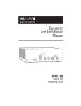
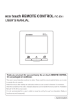
SUPPLIED ACCESSORIES
• FOR CLASS B UNINTENTIONAL RADIATORS:
The following accessories are supplied with the receiver.
qHand strap ��������������������������������������������������������������������� 1
wAntenna �������������������������������������������������������������������������� 1
eBelt clip ���������������������������������������������������������������������������1
rBattery pack* (BP-244) �������������������������������������������������� 1
tBattery charger* (BC-149A/D) ��������������������������������������� 1
This equipment has been tested and found to comply with
the limits for a Class B digital device, pursuant to part 15 of
the FCC Rules. These limits are designed to provide reasonable protection against harmful interference in a residential
installation. This equipment generates, uses and can radiate radio frequency energy and, if not installed and used
in accordance with the instructions, may cause harmful
interference to radio communications. However, there is no
guarantee that interference will not occur in a particular installation. If this equipment does cause harmful interference
to radio or television reception, which can be determined by
turning the equipment off and on, the user is encouraged to
try to correct the interference by one or more of the following
measures:
• Reorient or relocate the receiving antenna.
• Increase the separation between the equipment and receiver.
• Connect the equipment into an outlet on a circuit different from that to which the receiver is connected.
• Consult the dealer or an experienced radio/TV technician for help.
iii
(The shape of the BC-149A and BC-149D are different.)
*Not supplied with some versions.
q
w
r
t
e
OPERATING THEORY
Electromagnetic radiation which has frequencies of
20,000 Hz (20 kHz*) and above is called radio frequency
(RF) energy because it is useful in radio transmissions. The
IC-RX7 receives RF energy from 0.150 MHz* to 1300 MHz
and converts it into audio frequency (AF) energy which in
turn actuates a loudspeaker to create sound waves. AF energy is in the range of 20 to 20,000 Hz.
*kHz is an abbreviation of kilohertz or 1000 hertz, MHz is abbreviation of megahertz or 1,000,000 hertz, where hertz is a unit of frequency.
OPERATING NOTES
The IC-RX7 may receive its own oscillated frequency, resulting in no reception or only noise reception, on some frequencies.
The IC-RX7 may receive interference from extremely strong
signals on different frequencies or when using an external
high-gain antenna.
Icom, Icom Inc. and the
logo are registered trademarks of Icom
Incorporated (Japan) in the United States, the United Kingdom,
Germany, France, Spain, Russia and/or other countries.
Microsoft, Windows and Windows Vista are either registered trademarks or trademarks of Microsoft Corporation in the United States
and/or other countries.
iv
TABLE OF CONTENTS
FOREWORD······················································································ i
FEATURES························································································· i
IMPORTANT······················································································· i
EXPLICIT DEFINITIONS···································································· i
PRECAUTIONS················································································· ii
FCC INFORMATION········································································ iii
SUPPLIED ACCESSORIES····························································· iii
OPERATING THEORY····································································· iv
OPERATING NOTES······································································· iv
TABLE OF CONTENTS ·······························································v–vii
1
ACCESSORY ATTACHMENT······················································1
■ Antenna····················································································1
■ Belt clip·····················································································1
■ Hand strap················································································2
■ Battery installation····································································2
■ Optional battery case································································3
2 PANEL DESCRIPTION····························································4–9
■ Front, top and side panels························································4
■ Function display········································································7
vi
3
BATTERY CHARGING························································10–13
■ Caution···················································································10
■ Charging·················································································12
■ Battery information·································································13
■ External DC power operation··················································13
4
BASIC OPERATION····························································14–19
■ Power ON···············································································14
■ Setting audio volume······························································14
■ Setting squelch level·······························································15
■ Monitor function······································································15
■ Operating mode selection·······················································16
■ Receiving mode selection·······················································19
5 FREQUENCY SETTING······················································20–23
■ Setting a frequency·································································20
■ Setting a tuning step·······························································23
6
SEARCH AND SCAN OPERATIONS··································24–46
■ Search and scan types···························································24
■ Full search ·············································································26
■ Basic search ··········································································26
■ Band search ··········································································27
■ Program search ·····································································28
■ Program link search································································29
■ Search edges programming ··················································30
■ Program link programming ····················································32
■ Auto write search ···································································34
■ Skip search ············································································36
■ Priority watch during search ··················································37
■ Other SEARCH menu items ··················································38
■ Link scan ··············································································39
■ All scan ·············································································40
■ Category scan ······································································40
■ Group scan ···········································································41
■ Weather channel operation ····················································42
■ Skip setting for scanning·························································44
■ Priority watch during scan ·····················································45
■ Other SCAN menu items························································46
7 MEMORY PROGRAMMING··················································47–56
■ General description································································47
TABLE OF CONTENTS
■ Memory channel programming···············································48
■ Selecting a memory channel··················································53
■ Copying memory contents······················································54
■ Memory clearing·····································································56
8 MENU SCREEN OPERATION···············································57–70
■ General ···············································································57
■ Menu list ···············································································58
■ MODE/TS/TONE set items·····················································60
D Duplex direction (DUPLEX)················································60
D Offset frequency (OFFSET FREQ)·····································60
D Tuning step (TS)·································································61
D Receiving mode (MODE)····················································61
D Tone squelch/DTCS squelch setting (TONE)·····················62
D Tone squelch frequency (TSQL FREQ)······························62
D DTCS code (DTCS CODE)················································63
D DTCS polarity (DTCS POLARITY)·····································63
D Voice squelch control (VSC)···············································63
■ SETTING menu items·····························································64
D AM antenna selection (AM ANTENNA)······························64
D FM antenna selection (FM ANTENNA)······························64
D RF gain (RF GAIN)·····························································65
D Auto power OFF (AUTO POWER OFF)······························65
D Auto power ON (AUTO POWER ON)·································65
D Power save (POWER SAVE)··············································65
D Dial acceleration (DIAL SPEED-UP)··································66
D Key lock type (LOCK)·························································66
D CI-V setting (CI-V SET)······················································67
• CI-V address (ADDRESS)················································67
• CI-V baud rate (BAUD RATE)···········································67
• CI-V transeive (TRANSCEIVE)········································67
■ SOUNDS menu items·····························································68
D Key-touch beep (KEY-TOUCH BEEP)································68
D Beep output level (BEEP LEVEL)·······································68
D AF filter (AF FILTER)··························································68
D Tone control (TONE CONTROL)········································69
• Bass level (BASS)····························································69
• Treble level (TREBLE)······················································69
■ DISPLAY menu items·····························································70
D Display backlighting (BACKLIGHT)····································70
D LCD contrast (LCD CONTRAST)·······································70
D Opening logo (OPENING LOGO)·······································70
D Font size (FONT SIZE)·······················································70
9 OTHER FUNCTIONS·····························································71–85
■ Antenna selection···································································71
■ RF gain···················································································72
■ Attenuator function··································································73
■ Lock function···········································································73
■ Duplex operation·····································································74
■ [DIAL] function assignment·····················································75
■ Tone/DTCS squelch operation················································76
■ Tone squelch frequency/DTCS code setting ··························78
■ DTCS polarity·········································································79
■ Tone search············································································80
■ Beep tones·············································································81
■ Dial speed acceleration··························································81
■ Power save·············································································81
■ Auto power OFF·····································································82
■ Auto power ON·······································································82
■ Display backlighting································································82
■ Font size·················································································82
1
2
3
4
5
6
7
8
9
10
11
12
13
14
15
16
17
18
19
vii
TABLE OF CONTENTS
■ LCD contrast···········································································83
■ Voice squelch control······························································83
■ Cloning function······································································84
■ Resetting················································································85
10 CONTROL COMMAND························································86–87
■ General ···············································································86
■ Data format·············································································86
■ Command table······································································86
11 TROUBLESHOOTING································································88
12 SPECIFICATIONS······································································89
13 OPTIONS···················································································90
14 CE ······················································································91–92
INDEX ······················································································93–95
viii
ACCESSORY ATTACHMENT
1
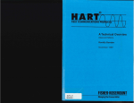
■ Antenna
■ Belt clip
Insert the supplied antenna into the antenna connector and
screw down the antenna as shown below.
Slide the supplied belt clip on the receiver’s rear panel until it
clicks into place.
NEVER carry the receiver by holding the antenna.
Antenna
1
Belt clip
Pull this lever when
dettached
✔ For your information
hird-party antennas may increase receiver performance.
T
An optional AD-92SMA antenna connector adapter is
available to connect an antenna with a BNC connector.
1
ACCESSORY ATTACHMENT
■ Hand strap
■ Battery installation
Slide the hand strap
through the loop on the
right top of the receiver
as illustrated at right to
facilitate carr ying the
receiver.
Install the Li-Ion battery pack (BP-244) or optional battery
case (BP-262) as illustrated below.
qRemove the battery cover from the receiver.
Handstrap
Latch
wInstall the Li-Ion battery pack (BP-244).
• Be sure to observe the correct direction.
• Charge the Li-Ion battery pack before use. (p. 12)
Facing up this side
Keep the jack cover attached when jacks are not in use to
avoid bad contacts from dust and moisture.
ACCESSORY ATTACHMENT
1
■ Optional battery case
eAttach the battery cover to the receiver.
➥Install 3 × LR6 (AA) size alkaline batteries into the optional BP-262 battery case.
Keep battery contacts clean. It’s a good idea to clean battery terminals once a week.
• BP-262 installation
• Be sure to observe the correct polarity.
D Battery information
The batteries may seem to have low capacity when used in
low temperatures such as –10°C (+14°F) or below. Keep the
battery case or pack warm in this case.
D Battery replacement
When the batteries become exhausted, the function display
may blink or have a lower contrast. In these cases, replace
all batteries with new, same brand, alkaline batteries.
1
2
3
4
5
6
7
8
9
10
11
12
13
14
15
16
17
18
19
2
PANEL DESCRIPTION
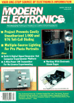
■ Front, top and side panels
t
q
r
SP
Function display
MENU
NO.
DIAL
SQL
w
e
DC 6V
ENT
CLR
MW
HOLD V
1
2
3
SCAN
4
5
6
SEARCH
7
8
9
ATT
0
SKIP
.
Speaker
Front view
Side view
qANTENNA CONNECTOR (p. 1)
Connects the supplied antenna.
• An optional AD-92SMA adapter (p. 90) is available for connecting an antenna with a BNC connector.
wKEYPAD (pgs. 5, 6)
eEXTERNAL DC IN JACK [DC 6V]
Connects a battery charger or an optional CP-18A/E
cigarette lighter cable for both charging the installed rechargeable battery pack and operating.*
rEXTERNAL SPEAKER/CLONE JACK [SP]
Connect a clone cable, optional speaker or earphone, if
desired.
See page 90 for a list of available options.
➥Connect an optional earphone or headphone.
The internal speaker will not function when any external equipment is connected.
➥Connects to a PC using an optional OPC-478/UC cloning cable for cloning. Cloning allows you to quickly and
easily transfer the programmed contents between the
IC-RX7 and the connected PC. (p. 84)
➥Connect an optional CT-17 for remote control operation.
(p. 87)
tCONTROL DIAL [DIAL]
➥ During VFO mode or search holding state, rotate to
tune the operating frequency. (p. 22)
➥ During memory mode or scan holding state, rotate to
select the memory channel. (p. 53)
➥ While searching or scanning, changes the direction.
(p. 18)
➥ W hile monitor function is active, rotate to set the
squelch level. (p. 15)
➥ While in menu mode, rotate to select the set items or
values. (p. 57)
The assigned function for [DIAL] and [r]/[s] can be exchanged by pushing and holding [NO. DIAL].
PANEL DESCRIPTION
2
KEYPAD
2
NO.
MENU
DIAL
CLR
ENT
SQL
MW
HOLD V
1
2
3
SCAN
4
5
6
7
8
9
ATT
0
SKIP
SEARCH
.
NUMERAL KEYS [0] to [9]
➥ Enter the frequency in VFO mode or memory
0
programming state. (pgs. 20, 21, 53)
➥ After pushing [NO. DIAL], select the memory
name number directly in scan mode. (p. 53)
9
➥ After pushing [• ATT], turn the scan link setting ON and OFF in scan mode. (p. 49)
NUMBER/SQUELCH KEY [NO. DIAL]
➥ After pushing this key, push numeral keys to
NO.
select the memory channel name in the memDIAL
ory group directly in scan mode. (p. 53)
➥ P ush and hold for 1 sec. to exchange the
assigned functions for [DIAL] and [r]/[s] .
(p. 75)
CLEAR/SQUELCH KEY [CLR SQL]
➥ Aborts numeral key input. (p. 20)
CLR
➥ Push to return to previous operating condition
SQL
while memory channel programming or while
in menu screen operation. (p. 57)
➥ Push and hold for 1 sec. to open the squelch
temporarily and monitor the operating frequency. (p. 15)
➥ After pushing and holding this key for 1 sec.,
rotate [DIAL] to adjust the squelch level.
(p. 15)
HOLD/VFO KEY [HOLD V]
➥ Push to stop searching or scanning temporarHOLD V
ily, and push again to return previous condition. (p. 18)
➥ Push and hold for 1 sec. to select VFO mode.
(p. 16)
SCAN KEY [SCAN]
➥ Push to start a scan. (p. 18)
SCAN
➥ Push and hold for 1 sec. to enter SCAN menu.
SEARCH
SEARCH KEY [SEARCH]
➥ Push to start a search. (p. 26)
➥ P ush and hold for 1 sec. to enter SEARCH
menu.
2
PANEL DESCRIPTION
]
POWER KEY [
Push for 1 sec. to turn the receiver power ON
and OFF. (p. 14)
ATTENUATOR KEY [• ATT]
➥ Push to input MHz digit for frequency entry.
ATT
(pgs. 20, 21)
➥ After pushing this key, push numeral keys to
turn the link setting ON and OFF during link
scan. (p. 49)
• Direct key number 0 to 9 can be selected by numeral key only.
➥ Push and hold for 1 sec. to turn the attenuator
function ON and OFF. (p. 73)
SKIP KEY [SKIP]
➥ Push to set the memory channel as the followSKIP
ing skip channel during scan holding state in
order. (p. 44)
• Skip channel — “SKIP” appears.
• Frequency skip channel — “PSKIP” appears.
• Non-skip channel — no skip indicator appears.
➥ Push and hold for 1 sec. to program a paused
frequency as a skip frequency during search.
(p. 36)
➥ Push and hold for 1 sec. to select the group
skip setting ON and OFF during link scan. (p.
44)
ENTER/MEMORY WRITE KEY [ENT MW]
ENT ➥ D uring VFO mode, search holding state or
scan holding state, push to enter memory proMW
gramming state. (p. 48)
➥ Push and hold for 1 sec. to turn the auto write
search function ON and OFF. (p. 34)
➥ Push and hold for 2 sec. to write the operating
frequency into the selected memory channel
in memory programming state.
MENU/LOCK KEY [MENU
]
➥ Push to select menu screen indication ON. (p. 57)
MENU
➥ P ush and hold for 1 sec. to toggle the lock
function ON and OFF. (p. 73)
LEFT/RIGHT KEY [v]/[w]
➥ D uring VFO mode or search mode, push to
select the operating frequency band. (p. 16)
➥ During VFO mode, push and hold for 1 sec. to
select and toggle 1 MHz and 10 MHz tuning
steps. (p. 22)
➥ During memory mode or scan mode, push to
select the group. (p. 18)
➥ During memory mode or scan mode, push and
hold for 1 sec. to select the category. (p. 18)
UP/DOWN/VOLUME CONTROL KEY [r]/[s]
➥ Adjust audio volume level. (p. 14)
➥ While in menu screen operation, push to select the set items or values. (p. 57)
The function of tuning control and volume control
can be traded. See page 75 for details.
PANEL DESCRIPTION
2
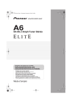
■ Function display
@0
!9 !8 !7 !6 !5 !4
q
!3
w
e
r
t
!2
!1
y u
i
o
!0
qBATTERY INDICATOR (p. 13)
m When BP-244 is attacched
➥ “
” (battery indicator) appears when the battery
pack has ample capacity.
➥ “
” appears when the battery pack is nearing exhaustion, and it must be charged.
➥ “
” blinks before the battery pack is exhausted.
➥ The indicator shows “
,” “
” and “
(disappears)” in sequence while charging the attached battery pack.
m When BP-262 is attacched
➥ “
” (battery indicator) appears when the installed
batteries have ample capacity.
➥ “
” appears when the installed batteries are nearing exhaustion.
2
wICON INDICATOR (p. 48)
Displays a variety of icon.
• Following 23 icons are available for category programming,
TRUCK, BUS, CAR, RACE CAR, TAXI, MOTORCYCLE,
TRAIN, SHIP, YACHT, AIRCRAFT, GLIDER, HAM, HAM HH,
RADIO, TV, EMERGENCY, FIRE, WEATHER, HUMAN, ANIMAL, BUILDING, HOUSE and PROGRAM SEARCH.
eCATEGORY INDICATOR
➥D
uring memory mode or scan mode, the programmed
memory category is displayed.
➥D
uring search mode operation, the searching category
is displayed.
2
PANEL DESCRIPTION
@0
rMEMORY GROUP INDICATOR (p. 51)
Displays a programmed memory group during memory
mode or scan mode operation.
!9 !8 !7 !6 !5 !4
q
!3
w
e
r
t
tFREQUENCY READOUT
Displays a variety of information, such as operating frequency, memory names.
• The decimal point blinks during search.
!2
yRECEIVING MODE INDICATOR (p. 19)
Shows the selected receiving mode.
• FM, WFM and AM are available, depending on operating band.
!1
y u
i
o
!0
uS-METER
Shows the relative signal strength while receiving signals.
iPRIORITY WATCH INDICATOR (pgs. 37, 45)
Appears when priority watch is in use.
oSKIP INDICATOR
➥ “SKIP” appears when the selected memory channel is
set as a skip channel. (p. ??)
➥ “PSKIP” blinks during skip search operation. (p. 36)
!0AUTO WRITE SEARCH INDICATOR
Blinks during auto write search operation. (p. 34)
!1MEMORY NUMBER INDICATOR
Shows the selected memory number. (pgs. 52, 53)
• This number is assigned to memory name and use this number
for memory management in each memory group.
Memory organization: Category u Group u Name u Channel
PANEL DESCRIPTION
2
!2STATUS INDICATOR
Shows the receiver’s status such as “HOLD,” “SCAN,”
“SEARCH” or “MEMORY.”
!7VOICE SQUELCH CONTROL INDICATOR (p. 83)
Appears when VSC (Voice squelch control) function is in
use.
!3KEY LOCK INDICATOR (p. 73)
Appears when the key lock function is activated.
!8DUPLEX INDICATOR (pgs. 74, 75)
“+DUP” appears when plus duplex, “–DUP” appears when
minus duplex is selected.
!4DIAL STATUS INDICATOR (p. 75)
➥ “DIAL” appears when [DIAL] is assigned as frequency
control.
• In this case, [r]/[s] keys are activate for volume control.
➥ “VOL” appears when the [DIAL] is assigned as volume
control.
• In this case, [r]/[s] keys are activate for frequency control.
!5AUTO POWER OFF INDICATOR (p. 82)
Appears when the auto power OFF function is in use.
!6TONE SQUELCH INDICATOR (pgs. 76, 77)
Available only when FM mode is selected.
➥ “TSQL” appears while the tone squelch function is in
use. (p. 124)
➥ “T SQL-R” appears while the reverse* tone squelch
function is in use. (p. 124)
➥ “DTCS” appears while the DTCS squelch function is in
use. (p. 124)
➥ “DTCS-R” appears while the reverse* DTCS squelch
function is in use. (p. 124)
➥ “S ” appears with the “TSQL” or “DTCS” indicator
while the pocket beep function (with CTCSS or DTCS) is
in use. (p. 125)
*: Reverse tone squelch or reverse DTCS squelch closes when
the signal is received with matched tone or DTCS.
!9RF GAIN INDICATOR (p. 72)
“RF” appears when the RF gain is adjusted other than
“MAX.”
@0ATTENUATOR INDICATOR (p. 73)
Appears when the RF attenuator is in use.
1
2
3
4
5
6
7
8
9
10
11
12
13
14
15
16
17
18
19
3
BATTERY CHARGING
■ Caution
Misuse of Lithium-Ion batteries may result in the following hazards: smoke, fire, or the battery may rupture.
Misuse can also cause damage to the battery or degradation of battery performance.
•R
DANGER! Use and charge only specified Icom battery
packs with Icom radios. Only Icom battery packs are tested
and approved for use with Icom radios. Using third-party or
counterfeit battery packs may cause smoke, fire, or cause
the battery to burst.
D Battery caution
•R
DANGER! DO NOT hammer or otherwise impact the
battery. Do not use the battery if it has been severely impacted or dropped, or if the battery has been subjected to
heavy pressure. Battery damage may not be visible on the
outside of the case. Even if the surface of the battery does
not show cracks or any other damage, the cells inside the
battery may rupture or catch fire.
•R
DANGER! NEVER use or leave battery pack in areas
with temperatures above +60˚C (+140˚F). High temperature buildup in the battery, such as could occur near fires
or stoves, inside a sun heated car, or in direct sunlight
may cause the battery to rupture or catch fire. Excessive
temperatures may also degrade battery performance or
shorten battery life.
10
•R
DANGER! DO NOT expose the battery to rain, snow,
seawater, or any other liquids. Do not charge or use a wet
battery. If the battery gets wet, be sure to wipe it dry before
using.
•R
DANGER! NEVER incinerate a used battery pack since
internal battery gas may cause it to rupture, or may cause
an explosion.
•R
DANGER! NEVER solder the battery terminals, or
NEVER modify the battery pack. This may cause heat generation, and the battery may burst, emit smoke or catch
fire.
•R
DANGER! Use the battery only with the receiver for
which it is specified. Never use a battery with any other
equipment, or for any purpose that is not specified in this
instruction manual.
•R
DANGER! If fluid from inside the battery gets in your
eyes, blindness can result. Rinse your eyes with clean
water, without rubbing them, and see a doctor immediately.
•W
ARNING! Immediately stop using the battery if it emits
an abnormal odor, heats up, or is discolored or deformed. If
any of these conditions occur, contact your Icom dealer or
distributor.
•W
ARNING! Immediately wash, using clean water, any part
of the body that comes into contact with fluid from inside
the battery.
BATTERY CHARGING
•W
ARNING! NEVER put the battery in a microwave oven,
high-pressure container, or in an induction heating cooker.
This could cause a fire, overheating, or cause the battery
to rupture.
•C
AUTION! Always use the battery within the specified
temperature range for the receiver (–10˚C to +60˚C; +14˚
F to +140˚F) and the battery itself (–20˚C to +60˚C; –4˚F to
+140˚F). Using the battery out of its specified temperature
range will reduce the battery’s performance and battery
life. Please note that the specified temperature range of the
battery may exceed that of the receiver. In such cases, the
receiver may not work properly because it is out of its operating temperature range.
•C
AUTION! Shorter battery life could occur if the battery
is left fully charged, completely discharged, or in an excessive temperature environment (above +50˚C; +122˚F)
for an extended period of time. If the battery must be left
unused for a long time, it must be detached from the radio
after discharging. You may use the battery until the battery
indicator shows half-capacity, then keep it safely in a cool
dry place with the below temperature range.
–20˚C (–4˚F) to +50˚C (+122˚F) (within a month).
–20˚C (–4˚F) to +35˚C (+95˚F) (within three months).
–20˚C (–4˚F) to +20˚C (+68˚F) (more than a year).
3
D Charging caution
•R
DANGER! NEVER charge the battery pack in areas with
extremely high temperatures, such as near fires or stoves,
inside a sun heated car, or in direct sunlight. In such environments, the safety/protection circuit in the battery will
activate, causing the battery to stop charging.
3
•W
ARNING! DO NOT charge or leave the battery in the receiver beyond the specified time for charging. If the battery
is not completely charged by the specified time, stop charging and remove the external DC power from the receiver.
Continuing to charge the battery beyond the specified time
limit may cause a fire, overheating, or the battery may rupture.
•C
AUTION! DO NOT charge the battery outside of the
specified temperature range: +5˚C to +35˚C (+41˚F to
+95˚F). Icom recommends charging the batter y at
+25˚C (+77˚F). The battery may heat up or rupture if
charged out of the specified temperature range. Additionally, battery performance or battery life may be reduced.
11
3
BATTERY CHARGING
■ Charging
Prior to using the receiver for the first time, the battery pack
must be fully charged for optimum life and operation.
DB
attery indicator and charging indicator
When the receiver’s power is ON, the battery indicator
shows “
,” “
” and “
(disappears)” in sequence
while charging, and indicator disappears when completely
charged.
qInsert the battery pack (BP-244) into the receiver. (p. 2)
wPlug the battery charger (BC-149A/D*) into an AC outlet;
or the optional CP-18A/E into a cigarette lighter socket.
* Not supplied with some versions.
eTurn OFF the receiver, then insert the adapter plug into
[DC 6V] of the receiver.
Optional CP-18A/E
Cigarette lighter cable
with DC-DC converter
When the receiver’s power is OFF, the charging indicator
shows “
,” “
” and “
” in sequence with “Charging...” while charging, and indicator disappears when completely charged.
to cigarette
lighter socket
to
[DC 6V]
jack
D Charging note
• Be sure to turn the receiver power OFF.
to AC outlet
Otherwise the battery pack will not be charged completely or takes
longer to charge time periods.
• E xternal DC power operation becomes possible when
using an optional CP-18A/E. The attached battery pack is
also charged simultaneously.
• If your battery pack seems to have no capacity even after
being charged, fully charge the battery pack again. If the
battery pack still does not retain a charge (or very little), a
new battery pack must be purchased.
12
IC-RX7
Turn power
OFF.
Battery charger BC-149A/D
Charging periods: approx. 5 hours
AUTION: BE SURE to disconnect the CP-18A/E from
C
the cigarette lighter socket when charging is finished, because, a slight current still follows in the CP-18A/E and
the vehicle’s battery will become exhausted.
BATTERY CHARGING
3
■ Battery information
■ External DC power operation
D Battery life
An optional cigarette lighter cable (CP-18A/E; for 12 V cigarette
lighter socket) can be used for external power operation.
The receiver operates with the BP-244 Li-ion battery pack or
BP-262 Battery case as follows.
• BP-244: Approx. 8.2 hours *1
• BP-262: Approx. 16.9 hours *1, *2
(Continuous receiving at rated AF output with backlight OFF)
*1 Operating time may differ depending on the operating conditions.
*2 Operating time may differ depending on the installed batteries.
ven when the receiver power is OFF, a small current still
E
flows in the receiver. Remove the battery pack or case from
the receiver when not using it for a long time. Otherwise, the
battery pack or installed batteries will become exhausted.
D Battery indicator
The battery indicator, “
” or “
” appears when the
BP-244 or BP-262 is attached to the receiver. And only when
BP-244 is attached, the battery indicator, “
,” blinks before the BP-244 is exhausted.
he battery indicator does not appear when turning power
T
ON after charging is completed to the BP-244 without disconnecting the battery charger or external DC power.
Indication
3
D Operating note
•B
E SURE to use CP-18A/E when connecting a regulated
12 V DC power supply.
Use an external DC-DC converter to connect the receiver
through optional CP-18A/E to a 24 V DC power source.
• The power save function is deactivated automatically during external DC power operation.
D CP-18A/E fuse replacement
If the fuse blows or the receiver stops functioning while operating with the optional CP-18A/E, find the source of the
problem if possible, and replace the damaged fuse with a
new rated one (FGB 5 A) as shown below.
Fuse 5 A
Battery condition
The battery pack or case has ample capacity.
The battery pack or case is nearing exhaustion.
Charging (BP-244) or replacing batteries (BP-262) is
necessary.
13
4
BASIC OPERATION
■ Power ON
➥ Push and hold [
■ Setting audio volume
] for 1 sec. to turn power ON.
➥ Push [r] or [s] several time to adjust the audio level.
• If squelch is closed, push and hold [CLR SQL] for 1 sec. to
activate the monitor function ON while setting the audio level
Push [CLR SQL] again to return to normal operating mode.
• The display shows the volume level while setting.
MENU
NO.
DIAL
ENT
CLR
SQL
MW
HOLD V
1
2
SCAN
4
5
SEARCH
7
8
9
ATT
0
SKIP
.
3
6
CLR
SQL
MENU
NO.
DIAL
ENT
CLR
SQL
MW
HOLD V
1
2
SCAN
4
5
SEARCH
7
8
9
ATT
0
SKIP
.
3
6
Volume level indicator
While in menu mode or
memory programming
state, audio volume
cannot be adjusted.
Minimum setting
(no audio)
Maximum setting
Beep level is adjustable in SOUNDS menu.
MENU ➪ SOUNDS ➪ BEEP LEVEL (p. 68)
14
BASIC OPERATION
4
■ Setting squelch level
■ Monitor function
The squelch circuit mutes the received audio signal depending on the signal strength. The receiver has 9 squelch levels,
a continuously open setting and an automatic squelch setting.
This function is used to listen to weak signals without disturbing the squelch setting or to open the squelch manually
even when mute functions such as the tone squelch are in
use.
➥ After pushing and holding [CLR SQL] for 1 sec., rotate
[DIAL] to select the squelch level.
➥ Push and hold [CLR SQL] for 1 sec. to monitor the operating frequency.
• “LEVEL 1” is loose squelch (for weak signals) and “LEVEL 9” is
tight squelch (for strong signals).
• “AUTO” indicates automatic level adjustment by a noise pulse
counting system.
• “OPEN” indicates continuously open setting.
• Push [CLR SQL] to return to normal operating mode.
CLR
[DIAL]
CLR
SQL
• Push [CLR SQL] to clear the monitor function.
SQL
MENU
NO.
DIAL
ENT
CLR
SQL
MW
HOLD V
1
2
SCAN
4
5
SEARCH
7
8
9
ATT
0
SKIP
.
3
6
The 1st segment blinks
MENU
NO.
DIAL
ENT
CLR
SQL
MW
HOLD V
1
2
SCAN
4
5
SEARCH
7
8
9
ATT
0
SKIP
.
3
6
Automatic squelch
Maximum level
he squelch adjustment is available when the monitor
T
function is activate. See left content for details.
1
2
3
4
5
6
7
8
9
10
11
12
13
14
15
16
17
18
19
15
4
BASIC OPERATION
■ Operating mode selection
D VFO mode
D Operating band selection
VFO mode is used for the desired frequency setting within
the frequency coverage.
The receiver can receive the AM broadcast, HF bands, 50
MHz, FM broadcast, VHF air, 144 MHz, 300 MHz, 400 MHz,
800 MHz* or 1200 MHz bands.
➥ Push and hold [HOLD V] for 1 sec. to select VFO mode.
➥ In VFO mode, push [v] or [w] several times to select the
desired frequency band.
• VFO mode indication
MENU
NO.
DIAL
ENT
CLR
SQL
HOLD V
MW
HOLD V
1
2
SCAN
4
5
SEARCH
7
8
9
ATT
0
SKIP
.
3
6
What is VFO?
VFO is an abbreviation of Variable Frequency Oscillator. Frequencies for receiving are generated and controlled by the
VFO.
Set the attenuator function ON (+p. 73) if the received
signal is blocked by other radio station when using a third
party high-gain antenna.
16
• If VFO mode is not selected, such as a scan mode or memory
mode, or weather channel,† push and hold [HOLD V] to select
VFO mode first, then push [v] or [w] to select the desired
band. († Available for USA and CANADA versions only.)
• Search mode is also selectable operating band.
Available frequency bands are different depending on version. See the specification for details. (p. 89)
* Some frequency ranges are blocked for the U.S.A. version by regulation.
BASIC OPERATION
• Available frequency bands
AM broadcast band
HF band
: Push
50 MHz band
FM broadcast band
: Push
1200 MHz band
Initial frequencies shown differ according to version.
800 MHz band
400 MHz band
300 MHz band
VHF air band
144 MHz band
4
1
2
3
4
5
6
7
8
9
10
11
12
13
14
15
16
17
18
19
17
4
BASIC OPERATION
D Search mode
D Scan mode
Search mode searches for signals for specified tuning steps
automatically and makes it easier to locate new stations for
listening purpose. Search mode is described more details at
Section 6—SEARCH AND SCAN OPERATIONS.
Scan mode searches for signals from the pre-programmed
memory channels automatically. Scan mode is described
more details at Section 6—SEARCH AND SCAN OPERATIONS.
qPush [SEARCH] to start a search.
qPush [SCAN] to start a scan.
• Search pauses when a signal is received.
• Rotate [DIAL] to change the searching direction.
• Scan pauses when a signal is received.
• Rotate [DIAL] to change the scanning direction.
wPush [v] or [w] several times to select the desired frequency band.
ePush [HOLD V] to stop the search temporarily, if desired.
wPush and hold [v] or [w] several times to select the desired category; or push [v] or [w] several times to select
the desired group.
ePush [HOLD V] to stop the scan temporarily, if desired.
• Rotate [DIAL] to change the frequency.
• Push [HOLD V] again to restart the search.
• Rotate [DIAL] to select the desired channel.
• Push [HOLD V] again to restart the scan.
[DIAL]
[DIAL]
• Search mode indication
• Scan mode indication
MENU
NO.
DIAL
ENT
CLR
SQL
HOLD V
SEARCH
MW
HOLD V
1
2
3
SCAN
4
5
6
SEARCH
.
7
8
9
ATT
0
SKIP
ENT
CLR
SCAN
Arrow indicates
searching direction
bout the searching steps: The selected tuning step in
A
each frequency band (in VFO mode) is used during
search.
18
MENU
NO.
DIAL
HOLD V
SQL
MW
HOLD V
1
2
SCAN
4
5
SEARCH
7
8
9
ATT
0
SKIP
.
3
6
Arrow indicates
scanning direction
hile scan holding condition, memory channels can be
W
selected by the rotating [DIAL].
BASIC OPERATION
■ Receiving mode selection
Receiving modes are determined by the modulation of the
radio signals. The receiver has 3 operating modes: FM,
WFM and AM modes. (And also auto mode is available for
USA version.) The mode selection is stored independently
for each operating band and memory channels. (Auto mode
is available for USA version only.)
Typically, AM mode is used for the AM broadcast stations
(0.495–1.620 MHz) and air band (118–136.995 MHz), and
WFM is used for FM broadcast stations (76–107.9 MHz).
qEnter “MODE” in MODE/TS/TONE… menu.
MENU ➪ MODE/TS/TONE ➪ MODE (p. 61)
(Push [MENU
[DIAL]
Push
MENU
MENU
MENU
NO.
DIAL
ENT
CLR
SQL
MW
HOLD V
1
2
3
SCAN
4
5
6
7
8
9
ATT
0
SKIP
SEARCH
.
ENT
MW
ENT
Push MW
]), (Push [r]/[s], then push [ENT MW].)
wPush [r]/[s] (or rotate [DIAL]) to set the mode.
ePush [ENT MW] (or [v]) to return to MODE/TS/TONE…
menu, and push [CLR SQL] to return to frequency indication.
ENT
Push MW
4
1
2
3
4
5
6
7
8
9
10
11
12
13
14
15
16
17
18
19
19
5
FREQUENCY SETTING
■ Setting a frequency
D Via the keypad
The frequency can be directly set via numeric keys.
• If a frequency outside the frequency range is entered, the previously displayed frequency is automatically recalled after editing
last digit.
qPush and hold [HOLD V] to select VFO mode, if necessary.
wEnter the desired frequency via the keypad.
•P
ushing [ENT MW] omits the entry of 100 kHz and
below, when you want to edit to those digits “0.”
• When a digit is mistakenly input, push [CLR SQL] to
abort input.
Depending on the tuning step setting, it may not be possible to input a 1 kHz digit. In this case, enter “0” as 1 kHz
digit, then rotate [DIAL] to set the desired frequency.
20
CLR
SQL
MENU
NO.
DIAL
ENT
CLR
SQL
MW
HOLD V
1
2
3
SCAN
4
5
6
SEARCH
7
8
9
ATT
0
SKIP
.
ENT
MW
.
1
2
3
4
5
6
7
8
9
ATT
0
FREQUENCY SETTING
5
D Display example
• Entering 0.820 MHz
.
• Entering 1260 MHz
• Changing 100 kHz
and below.
0
1
ATT
2
8
6
2
2
0
4
ENT
0
0
MW
Editing
1260.000 MHz
to 1260.240 MHz
.
5
ATT
21
5
FREQUENCY SETTING
D Via the dial
qPush and hold [HOLD V] for 1 sec. to select VFO mode, if
necessary.
wPush [v] or [w] to select the desired frequency band.
eRotate [DIAL] to select the desired frequency.
• The frequency changes according to the preset tuning steps.
See the next page for setting the tuning step.
[DIAL]
✔ CONVENIENT!
Push and hold [v] or [w] for 1 sec. then rotate [DIAL]
to change the frequency in 1 MHz steps, or push [v]
again then rotate [DIAL] to change the frequency in 10
MHz steps. (After entering MHz selection mode, pushing
[v] or [w] selects 10 MHz tuning steps or 1 MHz tuning
steps, respectively.)
MENU
NO.
DIAL
ENT
CLR
SQL
MW
HOLD V
1
2
SCAN
4
5
SEARCH
7
8
9
ATT
0
SKIP
.
3
6
[DIAL] changes the
frequency according to
the selected tuning step.
Push and hold
Push
or
CLR
SQL
for 1 sec.
Push
Push
22
FREQUENCY SETTING
■ Setting a tuning step
The tuning step can be selected for each frequency band.
The following tuning steps are available for the IC-RX7.
(Auto tuning step is available for USA version only.)
• 5.0 kHz • 6.25 kHz • 7.5 kHz • 8.33 kHz† • 9.0 kHz‡
• 10.0 kHz • 12.5 kHz • 15.0 kHz • 20.0 kHz • 25.0 kHz
• 30.0 kHz • 50.0 kHz • 100.0 kHz• 125.0 kHz • 200.0 kHz
†
‡
[DIAL]
Appears for the VHF air band only.
Appears for the AM broadcast band only.
MENU
ENT
CLR
SQL
qPush and hold [HOLD V] for 1 sec. to select VFO mode, if
necessary.
wPush [v] or [w] to select the desired frequency band.
eEnter “TS” in MODE/TS/TONE… menu.
MENU ➪ MODE/TS/TONE ➪ TS (p. 61)
(Push [MENU
MENU
MENU
NO.
DIAL
D Tuning step selection
Push
MW
HOLD V
1
2
3
SCAN
4
5
6
7
8
9
ATT
0
SKIP
SEARCH
.
ENT
MW
ENT
Push MW
]), (Push [r]/[s], then push [ENT MW].)
rPush [r]/[s] (or rotate [DIAL]) to select the tuning step.
tPush [ENT MW] (or [v]) to return to MODE/TS/TONE…
menu, and push [CLR SQL] to return to frequency indication.
ENT
Push MW
5
1
2
3
4
5
6
7
8
9
10
11
12
13
14
15
16
17
18
19
23
6
SEARCH AND SCAN OPERATIONS
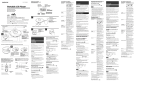
■ Search and scan types
Searching and scanning search for signals automatically and
makes it easier to locate new stations for listening purposes.
FULL SEARCH (p. 26)
Repeatedly searches all frequencies over the entire band.
Some frequency ranges are
not searched according to the
frequency coverage of the receiver’s version.
PROGRAM SEARCH (p. 28)
150
kHz
1300.000
MHz
Search
Jump
BASIC SEARCH (p. 26)
Repeatedly searches all
frequencies over the preprogrammed band by the optional
cloning software CS-RX7. Air,
Marine, Ham, Racing, Broadcast, and etc. are available.
Programmed band
Band
edge
Search
Jump
Edges
LOW
Band
HIGH edge
Search
Jump
Repeatedly searches userprogrammed frequencies
selected at PROGRAM LINK
item in the SEARCH menu.
Edges
LOW
Band
edge
No.01
Search
Band
edge
HIGH
LOW
Jump
Jump
Edges
No.02
Search
HIGH
Band
edge
AUTO WRITE SEARCH (p. 34)
Band
edge
Band
edge
Search
Jump
24
Band
edge
PROGRAM LINK SEARCH (p. 29)
Band
edge
BAND SEARCH (p. 27)
Repeatedly searches all frequencies over the entire selected band.
Repeatedly searches between
two user-programmed frequencies. Used for checking
for frequencies within a specified range such as repeater
output frequencies, etc.
The frequencies that the
search pauses on, are automatically stored into memory
channels.
Auto write
Edge channels
199
Edge
Search
Pause
Pause
3
2
1
SEARCH AND SCAN OPERATIONS
ALL MEMORY SCAN (p. 40)
GROUP SCAN (p. 41)
Repeatedly scans all memory channels.
Repeatedly scans all memory channels in the group.
HAM
HAM
HAM
AIR
Ricky
Group
F1
CREW
GROUP:
Team1
F1
AIR
6
John
F1
Tom
Category
Name
CATEGORY SCAN (p. 40)
LINK SCAN (p. 39)
Repeatedly scans all memory channels in the category.
Repeatedly scans all memory channels in the category/
group which selected in the category/group settings.
CATEGORY:
F1
Team3
Team3
Team3
Team2
LINK OFF
Category (AIR) is
set to link-OFF
Team1
AIR
Category
TV
Team2
Team1
Team1
Name
F1
LINK ON
LINK ON
HAM
Group
FREQUENCY/MEMORY SKIP FUNCTION (p. 44)
Skips unwanted frequencies or memory channels that
inconveniently stop searching (or scanning). This can be
turned ON/OFF by each memory channel/name/group/category.
LINK ON
Band
edge
Band
edge
Scan
SKIP
Jump
SKIP
1
2
3
4
5
6
7
8
9
10
11
12
13
14
15
16
17
18
19
25
6
SEARCH AND SCAN OPERATIONS
■ Full search
■ Basic search
qPush [SEARCH] to start a search.
qEnter “BASIC SEARCH” in SEARCH menu.
MENU ➪ SEARCH ➪ BASIC SEARCH
• Search pauses when a signal is received.
• Rotate [DIAL] to change the searching direction.
wPush [v] or [w] several times to select the desired frequency band.
ePush [HOLD V] to stop the search temporarily, if desired.
• Push [HOLD V] again to restart the search.
[DIAL]
(Push [MENU
]), (Push [r]/[s], then push [ENT MW].)
• S earch menu can also be entered by pushing and holding
[SEARCH] for 1 sec.
• 1st category appears.
wPush [r]/[s] (or rotate [DIAL]) to select the desired category, then push [ENT MW] to start the search.
• Search pauses when a signal is received.
• Rotate [DIAL] to change the searching direction.
• Search mode indication
ePush [HOLD V] to stop the search temporarily, if desired.
• Push [HOLD V] again to restart the search.
MENU
NO.
DIAL
ENT
CLR
SQL
HOLD V
SEARCH
MW
HOLD V
1
2
SCAN
4
5
SEARCH
7
8
9
ATT
0
SKIP
.
3
6
Arrow indicates
searching direction
MENU
MENU
NO.
DIAL
ENT
CLR
SQL
HOLD V
bout the searching steps: The selected tuning step in
A
each frequency band (in VFO mode) is used during
search.
26
MW
HOLD
1
2
3
SCAN
4
5
6
7
8
9
ATT
0
SKIP
SEARCH
.
ENT
Push MW
ENT
MW
ENT
Push MW
SEARCH AND SCAN OPERATIONS
■ Band search
qEnter “BAND SEARCH” in SEARCH menu.
MENU ➪ SEARCH ➪ BAND SEARCH
(Push [MENU
]), (Push [r]/[s], then push [ENT MW].)
• S earch menu can also be entered by pushing and holding
[SEARCH] for 1 sec.
• Band selection screen appears.
MENU
wPush [r] or [s] several times to select the desired frequency band, then push [ENT MW] to start the search.
• Search pauses when a signal is received.
• Rotate [DIAL] to change the searching direction.
• A fter started the search, searching frequency band can be
changed by pushing [v] or [w].
MENU
NO.
DIAL
ENT
CLR
SQL
MW
HOLD V
HOLD V
SCAN
SEARCH
.
1
2
4
5
7
8
9
ATT
0
SKIP
3
ENT
ENT
Push MW
MW
6
ePush [HOLD V] to stop the search temporarily, if desired.
• Push [HOLD V] again to restart the search.
ENT
Push MW
6
1
2
3
4
5
6
7
8
9
10
11
12
13
14
15
16
17
18
19
27
6
SEARCH AND SCAN OPERATIONS
■ Program search
qEnter “PROGRAM SEARCH” in SEARCH menu.
MENU ➪ SEARCH ➪ PROGRAM SEARCH
(Push [MENU
]), (Push [r]/[s], then push [ENT MW].)
• S earch menu can also be entered by pushing and holding
[SEARCH] for 1 sec.
• Program number selection screen appears.
MENU
wPush [r] or [s] several times to select the desired program number, then push [ENT MW] to enter the program.
• A total 25 program link numbers (No. 00 to No. 24) are available.
MENU
NO.
DIAL
ENT
CLR
SQL
HOLD V
MW
HOLD V
1
2
SCAN
4
5
SEARCH
7
8
9
ATT
0
SKIP
.
3
ENT
MW
ENT
Push MW
6
ePush [ENT MW] again to start the search.
• Search pauses when a signal is received.
• Rotate [DIAL] to change the searching direction.
• After started the search, program number can be changed by
pushing [v] or [w].
ENT
Push MW
rPush [HOLD V] to stop the search temporarily, if desired.
• Push [HOLD V] again to restart the search.
ENT
Push MW
28
SEARCH AND SCAN OPERATIONS
■ Program link search
qEnter “PROGRAM LINK SEARCH” in SEARCH menu.
MENU ➪ SEARCH ➪ PROGRAM LINK SEARCH
(Push [MENU
]), (Push [r]/[s], then push [ENT MW].)
• S earch menu can also be entered by pushing and holding
[SEARCH] for 1 sec.
• Program link number selection screen appears.
wPush [r] or [s] several times to select the desired program link number, then push [ENT MW] to enter the link
edit state.
• A total 10 program link numbers (No. 0 to No. 9) are available.
ePush [ENT MW] again to start the search.
• Search pauses when a signal is received.
• Rotate [DIAL] to change the searching direction.
• After started the search, program link number can be changed
by pushing [v] or [w].
MENU
NO.
DIAL
ENT
CLR
SQL
MW
HOLD V
HOLD V
SCAN
SEARCH
.
1
2
4
5
7
8
9
ATT
0
SKIP
3
ENT
MW
ENT
Push MW
6
SEARCH
ENT
Push MW
rPush [HOLD V] to stop the search temporarily, if desired.
• Push [HOLD V] again to restart the search.
NOTE: All program searches are linked in default settings.
Program links can be customized, see page 32 for programming details.
ENT
Push MW
6
1
2
3
4
5
6
7
8
9
10
11
12
13
14
15
16
17
18
19
29
6
SEARCH AND SCAN OPERATIONS
■ Search edges programming
Search edges programming can be stored frequency edges,
receiving mode, tuning steps, attenuator ON/OFF and
search name. But other items of the frequencies are not necessary to program. In this case, settings of each frequency
band are used to the search.
ePush [s] once to select “EDIT,” then push [ENT MW] (or
[w]).
qEnter “PROGRAM SEARCH” in SEARCH menu.
MENU ➪ SEARCH ➪ PROGRAM SEARCH
(Push [MENU
]), (Push [r]/[s], then push [ENT MW].)
• S earch menu can also be entered by pushing and holding
[SEARCH] for 1 sec.
• Program number selection screen appears.
wPush [r] or [s] several times to select the desired program number, then push [ENT MW] to enter the program.
rSet the desired edge frequencies either “LOW” or “HIGH.”
• Other items cannot be programmed until these frequencies are
input.
LOW:/HIGH:
q Push [ENT MW] (or [w]) to enter the frequency input.
MENU
MENU
NO.
DIAL
ENT
CLR
SQL
MW
HOLD V
1
2
SCAN
4
5
SEARCH
7
8
9
ATT
0
SKIP
.
3
ENT
MW
ENT
Push MW
w Edit the desired frequency with keypad (pgs. 20, 21).
6
e Push [r] or [s] to select another edge, then edit different frequency.
30
SEARCH AND SCAN OPERATIONS
6
tSet the other items, if desired.
NAME:
qP
ush [ENT MW] (or [w]) to edit the name programming.
wR
otate [DIAL] to select the desired character.
•T
he selected character blinks.
•P
ush [r] or [s] to select the character group from “ABC” (alphabetical characters; capital letters), “abc” (alphabetical characters; lower case letters), “123” (numbers) or “!”#” (symbols).
See next page for available characters details.
• Push [v] or [w] to move the cursor left or right, respectively.
• Push [CLR SQL] to clear the selected character.
eP
ush [ENT MW] to set the name and return to program
search edit state.
TS:/MODE:/ATT:
qP
ush [ENT MW] (or [w]) to edit the tuning step setting.
wP
ush and hold [r]/[s] (or rotate [DIAL]) to select the
desired setting.
• Push [v] or [w] to move the cursor left or right, respectively.
• Push [CLR SQL] to clear the selected character.
eP
ush [ENT MW] (or [w]) to set the setting.
rS
et the mode or attenuator settings as same as steps
q to e.
MODE
ATT
1
2
3
4
5
6
7
8
9
10
11
12
13
14
15
16
17
18
19
31
6
SEARCH AND SCAN OPERATIONS
■ Program link programming
Each program link can be programmed by linking program
searches (No. 00 to No. 24), and can be programmed with
an alphanumeric link name for easy recognition. Program
links are available a total 10 kind of links.
qEnter “PROGRAM LINK” in SEARCH menu.
MENU ➪ SEARCH ➪ PROGRAM LINK
(Push [MENU
ePush [s] several time to select the following operations.
NAME
qP
ush [ENT MW] (or [w]) to edit the link name programming.
• Push [r] or [s] to select the character group from “ABC”
]), (Push [r]/[s], then push [ENT MW].)
• S earch menu can also be entered by pushing and holding
[SEARCH] for 1 sec.
• Program link number selection screen appears.
(alphabetical characters; capital letters), “abc” (alphabetical
characters; lower case letters), “123” (numbers) or “!”#” (symbols).
• Push [v] or [w] to move the cursor left or right, respectively.
• Push [CLR SQL] to clear the selected character.
wPush [r] or [s] several times to select the desired program link number, then push [ENT MW] to enter the link
edit state.
wP
ush [ENT MW] to set the name and return to link edit
state.
MENU
MENU
NO.
DIAL
ENT
CLR
SQL
MW
HOLD V
SCAN
SEARCH
.
1
2
4
5
7
8
9
ATT
0
SKIP
3
6
ENT
MW
ENT
Push MW
• Available characters
ABCDEFGHIJKLMNOPQRSTUVWXYZ
abcdefghijklmnopqrstuvwxyz
0123456789
! ' # $ % & ' ( ) * + , - . / : ; < = > ? @ [ \ ] ^ _ ` { | } ~ (Space)
32
SEARCH AND SCAN OPERATIONS
CLEAR
qP
ush [ENT MW] (or [w]) to edit the link clearing.
• If all program searches are already cleared in the selected
program link number, this item cannot be edited.
wP
ush [r] or [s] to select the program search to be
unlinked.
eP
ush [ENT MW] (or [w]) to unlink the program search.
• “CLEAR?” window appears.
rP
ush [r] to select “YES,” then push [ENT MW] (or
[w]).
• Select “NO,” then push [ENT MW] to cancel clearing.
6
ADDITION
qP
ush [ENT MW] (or [w]) to edit the adding link.
• If all program searches are already linked in the selected
program link number, this item cannot be edited.
wP
ush [r] or [s] to select the desired program search.
eP
ush [ENT MW] to set the link.
rP
ush [v] to finish the adding link and return to link edit
state.
DETAIL
qP
ush [ENT MW] (or [w]) to enter the program link details.
• If no program searches are linked in the selected program
link number, this item cannot be entered.
Link return
clear to link
tP
ush Cancel
[v] to clearing
finish the link clearing and
edit state.
wP
ush [r] or [s] to select the program search.
eP
ush [ENT MW] (or [w]) to enter the program search.
rP
ush [v] to return to link edit state.
1
2
3
4
5
6
7
8
9
10
11
12
13
14
15
16
17
18
19
33
6
SEARCH AND SCAN OPERATIONS
■ Auto write search
This search is useful for searching a specified frequency
range and automatically storing busy frequencies into memory channels. The auto write search is performed with any
search types.
qPush [SEARCH] to start the full search.
• Any other searches are also available (see pages 26 to 29).
• Search pauses when a signal is received.
• Rotate [DIAL] to change the searching direction.
wPush and hold [ENT MW] for 1 sec. to turn the auto write
function ON and OFF.
• “AW” indicator blinks.
• During auto write search
MENU
NO.
DIAL
ENT
CLR
SQL
MW
HOLD V
SCAN
SEARCH
.
1
2
4
5
7
8
9
ATT
0
SKIP
3
ENT
MW
6
“AW” indicator blinks during
auto write search.
ePush [HOLD V] to stop the auto write search.
34
D During auto write searching:
• W hen a signal is received, search pauses and the frequency is stored into auto write channel group (CH000 –
CH199).
- 2 short beeps sound when stored.
• Search resumes after frequency storing.
• When all channels are stored, the search is cancelled automatically and 1 long beep sounds.
SEARCH AND SCAN OPERATIONS
6
D Recalling the stored frequencies:
D Clearing the stored frequencies:
qEnter “AUTO WRITE CH” in SEARCH menu.
MENU ➪ SEARCH ➪ AUTO WRITE CH
qSelect the auto write channel group.
wPush and hold [SKIP] for 1 sec. to clear the all channels
contents.
(Push [MENU
]), (Push [r]/[s], then push [ENT MW].)
• S earch menu can also be entered by pushing and holding
[SEARCH] for 1 sec.
• Auto write channel group appears.
• 1 short and 1 long beeps sound.
MENU
NO.
DIAL
ENT
CLR
SQL
MENU
MENU
NO.
DIAL
ENT
CLR
SQL
MW
HOLD V
SCAN
SEARCH
.
1
2
4
5
7
8
9
ATT
0
SKIP
3
ENT
MW
Push
ENT
MW
MW
HOLD V
1
2
SCAN
4
5
SEARCH
7
8
9
ATT
0
SKIP
.
3
6
SKIP
6
wRotate [DIAL] to select the desired channel.
OTE: The auto write channel contents CANNOT be
N
cleared by an independent channel. Thus it is a good idea
to copy the contents into regular memory channel.
1
2
3
4
5
6
7
8
9
10
11
12
13
14
15
16
17
18
19
35
6
SEARCH AND SCAN OPERATIONS
■ Skip search
During search operation, you can store the paused frequency into memory channel as a skip channel which is
skipped during search. This setting is useful to speed up the
search speed.
D Setting
qEnter “PROGRAM SKIP” in SEARCH menu.
MENU ➪ SEARCH ➪ PROGRAM SKIP
(Push [MENU
]), (Push [r]/[s], then push [ENT MW].)
• S earch menu can also be entered by pushing and holding
[SEARCH] for 1 sec.
wPush [r]/[s] (or rotate [DIAL]) to select the program
skip setting ON or OFF.
ePush [ENT MW] (or [v]) to return to SEARCH menu, and
push [CLR SQL] to return to frequency indication.
D Operation
qPush [SEARCH] to start the full search.
• Any other searches are also available (see pages 26 to 29).
• “PSKIP” indicator blinks.
• Search pauses when a signal is received.
• Rotate [DIAL] to change the searching direction.
wWhen search pauses and you want to set the paused frequency as a skip frequency.
Push and hold [SKIP] for 1 sec. to store the frequency
into skip channel group in program search category.
• Program search (category)/PSKIP1 (group) are made automatically when first skip channel is stored.
• 1 long beep and 2 short beeps sound when stored.
• During Program skip search
MENU
NO.
DIAL
ENT
CLR
SQL
MENU
MENU
NO.
DIAL
ENT
CLR
SQL
MW
HOLD V
1
2
3
SCAN
4
5
6
7
8
9
ATT
0
SKIP
SEARCH
.
ENT
MW
ENT
Push MW
MW
HOLD V
1
2
SCAN
4
5
SEARCH
7
8
9
ATT
0
SKIP
.
3
6
SKIP
“PSKIP” indicator blinks during
program skip search.
eAfter that, stored frequencies are skipped during search.
• This setting can be turned OFF by entering “PROGRAM SKIP”
in SEARCH menu (see left content for details).
36
SEARCH AND SCAN OPERATIONS
6
■ Priority watch during search
Priority watch checks for signals on the priority channels every
5 sec. while operating on a search. All programmed memory
channels can be set as priority channels at same time.
The watch resumes according to the selected search
resume condition. See page 89 for details.
qPush [SEARCH] to start the full search.
• Any other searches are also available (see pages 26 to 29).
• Search pauses when a signal is received.
• Rotate [DIAL] to change the searching direction.
rPush [ENT MW] (or [v]) to return to SEARCH menu, and
push [CLR SQL] to return to frequency indication and
start the watch.
• “PRIO” indicator appears.
• The receiver checks the priority channel(s) every 5 sec (see p.
53 for priority channel programming details).
• T he watch resumes according to the selected scan resume
condition (p. 46), or push [CLR SQL] to resume manually.
• During priority watch
wEnter “PRIORITY” in SEARCH menu.
MENU ➪ SEARCH ➪ PRIORITY
(Push [MENU
]), (Push [r]/[s], then push [ENT MW].)
ePush [r]/[s] (or rotate [DIAL]) to select “ON.”
• Select “BELL” if the priority beep function is desired.
Searches VFO frequencies
for 5 sec.
Pauses on a priority
channel when a signal is
received.
• During priority watch with priority beep
MENU
MENU
NO.
DIAL
ENT
CLR
SQL
MW
HOLD V
SCAN
SEARCH
.
1
2
4
5
7
8
9
ATT
0
SKIP
3
ENT
MW
ENT
Push MW
6
Emits beep and blinks “S” indicator when a signal is
received on a priority channel.
tPush [CLR SQL] to cancel the priority watch.
1
2
3
4
5
6
7
8
9
10
11
12
13
14
15
16
17
18
19
37
6
SEARCH AND SCAN OPERATIONS
■ Other SEARCH menu items
D Stop beep (STOP BEEP)
D Search resume timer (RESUME)
Selects the stop beep setting for search.
• OFF : The stop beep is turned OFF. (default)
• ON : The receiver emits a long beep when a search
pauses with signal is received.
Selects the search resume time from a pause after the received signal disappears.
• 0 SEC : Search resumes when a received signal disappears.
• 1–5 SEC : Search pauses 1–5 sec. after a received signal disappears. (default: 2 sec.)
• HOLD : S earch remains paused on the received
signal even if it disappears. Rotate [DIAL] to
resume manually.
D Search pause timer (PAUSE)
Selects the search pause time. When receiving signals, the
search pauses according to the search pause time.
• 2–20 SEC : Search pauses for 2–20 sec. on a received
signal in 2 sec. steps. (default: 10 sec.)
• HOLD
: Search pauses on a received signal until it
disappears. Rotate [DIAL] to resume manually.
earch resume timer must be set shorter than search
S
pause timer (previous item), otherwise this timer does not
activate.
D Tone search (TONE SEARCH)
This item appears only when FM mode is selected. See
page ?? for tone search details.
38
SEARCH AND SCAN OPERATIONS
6
■ Link scan
I MPORTANT!: To perform scan functions, 2 or more
memory channels MUST be programmed, otherwise the
scans will not start.
qPush [SCAN] to start a link scan.
• Scan pauses when a signal is received.
• Rotate [DIAL] to change the scanning direction.
wPush [HOLD V] to stop the scan temporarily, if desired.
• Push and hold [v] or [w] for 1 sec. several times to select the
desired category; or push [v] or [w] several times to select the
desired group.
• Push [HOLD V] again to restart the scan.
[DIAL]
• Search mode indication
MENU
NO.
DIAL
ENT
CLR
SQL
HOLD V
SEARCH
MW
HOLD V
1
2
SCAN
4
5
SEARCH
7
8
9
ATT
0
SKIP
.
3
6
Arrow indicates
searching direction
The category/group link setting can be changed in memory programming. See page 109 for details.
S can skips any memory channels in the selected category/group that are set to “SKIP” or “PSKIP.”
Link scan stops at the first channel when all channels in a
category/group are set to “SKIP” or “PSKIP.”
1
2
3
4
5
6
7
8
9
10
11
12
13
14
15
16
17
18
19
39
6
SEARCH AND SCAN OPERATIONS
■ All scan
■ Category scan
All scan repeatedly scans all memory channels programmed
with any frequencies in the memory channel selected for
scanning.
Category scan repeatedly scans all memory channels in the
same category as the selected memory channel has been
programmed.
qEnter “ALL” in SCAN menu.
MENU ➪ SCAN ➪ ALL
qEnter “CATEGORY” in SCAN menu.
MENU ➪ SCAN ➪ CATEGORY
(Push [MENU
]), (Push [r]/[s], then push [ENT MW].)
• S CAN menu can also be entered by pushing and holding
[SCAN] for 1 sec.
• Scan pauses when a signal is received.
• Rotate [DIAL] to change the scanning direction.
(Push [MENU
]), (Push [r]/[s], then push [ENT MW].)
• S CAN menu can also be entered by pushing and holding
[SCAN] for 1 sec.
wPush [HOLD V] to stop the scan temporarily, if desired.
• Push and hold [v] or [w] for 1 sec. several times to select the
desired category; or push [v] or [w] several times to select the
desired group.
• Push [HOLD V] again to restart the scan.
wPush [r]/[s] (or rotate [DIAL]) to select the desired category, then push [ENT MW].
• Scan pauses when a signal is received.
• Rotate [DIAL] to change the scanning direction.
MENU
MENU
NO.
DIAL
ENT
CLR
SQL
HOLD V
40
MW
HOLD
1
2
3
SCAN
4
5
6
7
8
9
ATT
0
SKIP
SEARCH
.
ENT
MW
ENT
Push MW
ePush [HOLD V] to stop the scan temporarily, if desired.
• Push and hold [v] or [w] for 1 sec. several times to select the
desired memory category; or push [v] or [w] several times to
select the desired group.
• Push [HOLD V] again to restart the scan.
SEARCH AND SCAN OPERATIONS
6
■ Group scan
Group scan repeatedly scans all memory channels in the
same group as the selected memory channel has been programmed.
qSelect the category that includes the desired group to be
scanned.
➥ Push [SCAN] to start a scan, then push [HOLD V] to
hold the scan.
➥ Push and hold [v] or [w] for 1 sec. to select the category.
wEnter “GROUP” in SCAN menu.
MENU ➪ SCAN ➪ GROUP
(Push [MENU
]), (Push [r]/[s], then push [ENT MW].)
• S CAN menu can also be entered by pushing and holding
[SCAN] for 1 sec.
eP ush [r]/[s] (or rotate [DIAL]) to select the desired
group, then push [ENT MW].
• Scan pauses when a signal is received.
• Rotate [DIAL] to change the scanning direction.
rPush [HOLD V] to stop the scan temporarily, if desired.
• Push and hold [v] or [w] for 1 sec. several times to select the
desired memory category; or push [v] or [w] several times to
select the desired group.
• Push [HOLD V] again to restart the scan.
MENU
MENU
NO.
DIAL
ENT
CLR
SQL
HOLD V
MW
HOLD
1
2
3
SCAN
4
5
6
7
8
9
ATT
0
SKIP
SEARCH
.
ENT
Push MW
ENT
MW
ENT
Push MW
1
2
3
4
5
6
7
8
9
10
11
12
13
14
15
16
17
18
19
41
6
SEARCH AND SCAN OPERATIONS
■ Weather channel operation
There are 10 weather channels for monitoring weather channels from the NOAA (National Oceanographic and Atmospheric Administration) broadcasts.
D Weather channel selection
qEnter “WEATHER SCAN” in SCAN menu.
MENU ➪ SCAN ➪ WEATHER SCAN
(Push [MENU
]), (Push [r]/[s], then push [ENT MW].)
• S CAN menu can also be entered by pushing and holding
[SCAN] for 1 sec.
• “WX” and the weather channel number appear.
wPush [HOLD V] to stop scanning.
eRotate [DIAL] to select the desired weather channel.
rP ush and hold [HOLD V] for 1 sec. to return to VFO
mode.
[DIAL]
MENU
MENU
NO.
DIAL
ENT
CLR
SQL
MW
HOLD V
HOLD V
SCAN
SEARCH
.
1
2
4
5
7
8
9
ATT
0
SKIP
3
6
ENT
MW
ENT
Push MW
U.S.A. and CANADA versions only
D Weather alert function
NOAA broadcast stations transmit weather alert tones before important weather announcements. When the weather
alert function is turned ON, the selected weather channel
is monitored every 5 sec. for the announcement. When the
alert signal is detected, the “ALT” and the WX channel are
displayed alternately and sounds a beep tone until the receiver is operated. The previously selected (used) weather
channel is checked periodically during standby or while
scanning.
qSelect the desired weather channel.
wEnter “WEATHER ALERT” in SCAN menu.
MENU ➪ SCAN ➪ WEATHER ALERT
(Push [MENU
]), (Push [r]/[s], then push [ENT MW].)
• S can menu can also be entered by pushing and holding
[SCAN] for 1 sec.
ePush [r]/[s] (or rotate [DIAL]) to select “ON” or “OFF.”
rPush [ENT MW] (or [v]) to return to SCAN menu, and
push [CLR SQL] to return to the weather channel indication.
tSet the desired stand-by condition.
• Select VFO or memory channel.
• Search, scan or priority watch operation can also be selected.
yWhen the alert is detected, a beep sounds and the following indication will be displayed.
uTurn the weather alert function OFF in SCAN menu.
42
SEARCH AND SCAN OPERATIONS
OTE: While receiving a signal (on a frequency other than
N
the weather alert ON frequency), the receiving signal or
audio will be interrupted momentarily every 5 sec. (approx.)
in the case that the alert function is turned ON. This symptom is caused by the WX alert function. To cancel these
symptoms, set the weather alert item OFF in SCAN menu.
[DIAL]
MENU
MENU
NO.
DIAL
ENT
CLR
SQL
MW
HOLD V
HOLD V
SCAN
SEARCH
.
1
2
4
5
7
8
9
ATT
0
SKIP
3
6
ENT
MW
ENT
Push MW
6
1
2
3
4
5
6
7
8
9
10
11
12
13
14
15
16
17
18
19
43
6
SEARCH AND SCAN OPERATIONS
■ Skip setting for scanning
Memory category/group/name can be set to be skipped
during scan. In addition, memory channels can be set to be
skipped during search. This is useful to speed up the scan/
search rate.
qEnter “SKIP” in SCAN menu.
MENU ➪ SCAN ➪ SKIP
(Push [MENU
]), (Push [r]/[s], then push [ENT MW].)
• S can menu can also be entered by pushing and holding
[SCAN] for 1 sec.
wP ush [v]/[w] once or twice to to select “CATEGORY,”
“GROUP” or “NAME.”
ePush [r]/[s] (or rotate [DIAL]) to select the category
(group/name) to be skipped.
rPush [SKIP] to set the skip state.
• Push [SKIP] again to cancel the skip state.
MENU
MENU
NO.
DIAL
ENT
CLR
SQL
MW
HOLD V
1
2
3
SCAN
4
5
6
7
8
9
ATT
0
SKIP
SEARCH
.
ENT
MW
ENT
Push MW
tPush [ENT MW] (or [v]) several times to return to SCAN
menu, and push [CLR SQL] to return to frequency indication.
✔ CONVENIENT!
The group skip setting can be set with the following operation during a scan or scan holding state.
qSelect the desired memory group to be skipped.
wPush and hold [SKIP] for 1 sec., and rotate [DIAL] to select the skip setting from “ON (skip)” and “OFF,” then push
[ENT MW].
44
SEARCH AND SCAN OPERATIONS
6
■ Priority watch during scan
Priority watch checks for signals on the priority channels every
5 sec. during a scan.
qPush [SCAN] to start the link scan.
• Any other scans are also available (see pages 39 to 41).
• Scan pauses when a signal is received.
• Rotate [DIAL] to change the scanning direction.
wEnter “PRIORITY” in SCAN menu.
MENU ➪ SCAN ➪ PRIORITY
(Push [MENU
rPush [ENT MW] (or [v]) to return to SCAN menu, and
push [CLR SQL] to exit the menu screen and start the
watch.
• “PRIO” indicator appears.
• The receiver checks the priority channel(s) every 5 sec (see p.
53 for priority channel programming details).
• T he watch resumes according to the selected scan resume
condition (p. 89), or push [CLR SQL] to resume manually.
]), (Push [r]/[s], then push [ENT MW].)
Pauses on a priority
channel when a signal is
received.
ePush [r]/[s] (or rotate [DIAL]) to select “ON.”
CH-999
CH-400
MENU
MENU
NO.
DIAL
ENT
CLR
SQL
MW
HOLD V
1
2
3
SCAN
4
5
6
SEARCH
7
8
9
ATT
0
SKIP
.
ENT
MW
CH-000
Scan operation
ENT
Push MW
CH-300
CH-001
Priority channels
CH-010
CH-200
every 5 sec.
CH-100
CH-002
CH-024
CH-99
CH-003
CH-006
CH-004
CH-005
tTurn the priority watch function OFF in SCAN menu.
1
2
3
4
5
6
7
8
9
10
11
12
13
14
15
16
17
18
19
45
6
SEARCH AND SCAN OPERATIONS
■ Other SCAN menu items
D Stop beep (STOP BEEP)
D Scan resume timer (RESUME)
Selects the stop beep setting for scan.
• OFF : The stop beep is turned OFF. (default)
• ON : T he receiver emits a long beep when a scan
pauses with signal is received.
Selects the scan resume time from a pause after the received signal disappears.
• 0 SEC : Scan resumes when a received signal disappears.
• 1–5 SEC : Scan pauses 1–5 sec. after a received signal
disappears. (default: 2 sec.)
• HOLD : Scan remains paused on the received signal even if it disappears. Rotate [DIAL] to
resume manually.
D Scan pause timer (PAUSE)
Selects the scan pause time. When receiving signals, the
scan pauses according to the scan pause time.
• 2–20 SEC : Scan pauses for 2–20 sec. on a received
signal in 2 sec. steps. (default: 10 sec.)
• HOLD
: S can pauses on a received signal until it
disappears. Rotate [DIAL] to resume manually.
46
can resume timer must be set shorter than scan pause
S
timer (previous item), otherwise this timer does not activate.
MEMORY PROGRAMMING
■ General description
The IC-RX7 can be programmed a total 1600 memory channels. And a total of 26 category are available for storing
groups of frequencies, etc.
The memory organization is as follow.
q Category : Max. 26
w Group : Max. 100 (in each category)
e Name : Max. 100 (in each group)
r CH
: Max. 6 (in each name)
CAUTION!
Memory data can be erased by static electricity, electric
transients, etc. In addition, they can be erased by malfunction and during repairs. Therefore, we recommend that
memory data be written down or be saved to a PC using
the optional CS-RX7 cloning software.
Memory channels
q
Category 01
w
Category 02
D Memory channel contents
Group 01
The following information can be programmed into memory
channels:
• Operating frequency (pgs. 20, 21)
• D uplex direction (+DUP or –DUP) with an offset frequency (p. 74)
• Tuning step (p. 61)
• Receiving mode (p. 61)
• Attenuator ON/OFF (p. 73)
• Skip setting (p. ??)
• Priority setting (p. ??)
• Stop beep (p. 46)
• Tone squelch or DTCS squelch ON/OFF (p. 62)
• Tone squelch frequency or DTCS code with polarity
e
Group 02
Name 01
Name 02
CH 1
CH 2
CH 3
CH 4
CH 5
CH 6
Name 03
Name 100
Group 03
(pgs. 62, 63)
• VSC setting (p. 63)
7
Group 100
Category 03
Category 26
r
1
2
3
4
5
6
7
8
9
10
11
12
13
14
15
16
17
18
19
47
7
MEMORY PROGRAMMING
■ Memory channel programming
qPush and hold [HOLD V] for 1 sec. to select VFO mode.
wSet the desired frequency, if desired:
• Frequency or any other data can be set while in CH programming state.
➥ Select the desired band with [v] or [w].
➥ Set the desired frequency with [DIAL].
➥ Or set the desired frequency with keypad directly.
In this case, the band and frequency settings with
[v]/[w] and [DIAL] as above are not required.
➥ Set other data (e.g. offset frequency, duplex direction,
tone squelch, etc.) in the Menu screen.
ePush and hold [ENT MW] for 1 sec. to enter memory programming mode.
• 1 short and 1 long beep sound.
• Category selection screen appears.
✔ STORING SEARCHED FREQUENCY:
While in a serach holding state, the displayed frequency,
receiving mode and other data can also be stored into
memory channel as follwing operation instead above q to e.
qStart a search.
• Search pauses when a signal is received.
• Rotate [DIAL] to restart the search.
wPush [HOLD V] to hold the search, if you want to store the
paused frequency into memory channel.
ePush and hold [ENT MW] for 1 sec. to enter the memory
programming mode.
48
rPush [r] or [s] (or rotate [DIAL]) to select the desired
category or “ADDITION,” then push [ENT MW].
• W hen “ADDITION” is selected, new category can be programmed (see p. 50 for new category programming details).
tPush [r] or [s] (or rotate [DIAL]) to select the desired
group or “ADDITION,” then push [ENT MW].
• When “ADDITION” is selected, new group can be programmed
in the category (see p. 51 for new group programming details).
MEMORY PROGRAMMING
yPush [r] or [s] (or rotate [DIAL]) to select the desired
name or “ADDITION,” then push [ENT MW].
• When “ADDITION” is selected, new name can be programmed
in the group (see p. 52 for new name programming details).
uPush [r] (or rotate [DIAL]) to select “ADDITION,” then
push [ENT MW].
• After “ADDITION” is selected, new channel can be programmed
in the name (see p. 53 for new channel programming details).
7
iAfter all data are programmed, push and hold [ENT MW]
for 1 sec. to store the channel and return to frequency display.
What is DIRECT KEY
The IC-RX7 has a total of 100 direct keys in the same
category (00 to 99). Direct key is used to turn the link
setting ON/OFF for the assigned category or group during
link scan.
qPush [SCAN] to start the link scan.
• Scan pauses when a signal is received.
• Rotate [DIAL] to restart the scan.
wPush [HOLD V] to hold the scan.
➥ Push a numeral key (0 to 9) to the link setting ON
or OFF for the category or group which assigned a
direct key (00 to 09).
➥ Or push [• ATT] and 2 digit number (00 to 99) to
the link setting ON or OFF for the category or group
which assigned a direct key (00 to 99).
➥ Or push [• ATT] and a numeral key (0 to 9), then
push [ENT MW] to the link setting ON or OFF for
the category or group which assigned a direct key
(00 to 09).
1
2
3
4
5
6
7
8
9
10
11
12
13
14
15
16
17
18
19
49
7
MEMORY PROGRAMMING
D New CATEGORY programming
qPush [r] or [s] (or rotate [DIAL]) to select the desired
information, then push [ENT MW].
Selectable information:
• NAME
• ICON
• SKIP
• LINK
• NEXT (Edit GROUP programming)
• DIRECT KEY
SKIP, LINK
qP
ush [ENT MW] (or [w]) to edit the setting state.
wP
ush [r] or [s] to select the desired setting, then
push [ENT MW].
NAME (Category name)
qPush [ENT MW] (or [w]) to edit the name programming.
• Push [r] or [s] to select the character group from “ABC”
(alphabetical characters; capital letters), “abc” (alphabetical
characters; lower case letters), “123” (numbers) or “!”#” (symbols). See next page for available characters details.
• Push [v] or [w] to move the cursor left or right, respectively.
• Push [CLR SQL] to clear the selected character.
ICON
qP
ush [ENT MW] (or [w]) to edit the setting state.
wP
ush [r] or [s] (or [v]/[w]) to select the desired icon,
then push [ENT MW].
50
DIRECT KEY
qP
ush [ENT MW] (or [w]) to enter the number input.
wE
dit the desired 2 digit number with keypad.
• Duplicated number can not be assigned in the same category (including direct key for group).
wPush [s] (or rotate [DIAL]) to select “NEXT,” then push
[ENT MW] to enter the GROUP programming state.