1
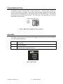
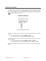
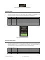
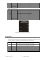
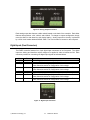
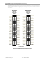
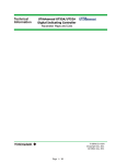
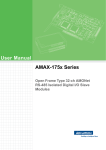
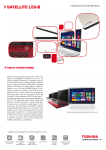
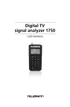
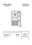
rapid Hardware Overview Version 1.0 Wineman Technology Incorporated Corporate Office 1668 Champagne Drive Saginaw, MI 48604 Ph: 989-771-3000 Fax: 989-771-3010 E-Mail: [email protected] URL: www.WINEMANTECH.com TABLE OF CONTENTS Introduction .......................................................................................... 1-1 About the RAPID Controller ................................................................................................ 1-1 Connecting External Power ................................................................................................ 1-2 Status LEDs ........................................................................................................................ 1-2 Configuring Safeties and Excitation................................................... 2-1 E-Stop Circuit...................................................................................................................... 2-1 Network Connection ...........................................................................................................2-2 Excitation Power Selection ................................................................................................. 2-3 Wiring Signals and Sensors ................................................................ 3-4 Analog Inputs ...................................................................................................................... 3-4 Frequency Inputs ................................................................................................................ 3-5 Expansion Analog Inputs .................................................................................................... 3-5 Analog Outputs ................................................................................................................... 3-6 Digital Inputs (Front Connectors) ........................................................................................ 3-7 Digital Outputs (Front Connectors) ..................................................................................... 3-8 Digital TTL Inputs and Outputs (Rear Connectors) ............................................................ 3-9 Digital 24VDC Inputs and Outputs (Rear Connectors) .................................................... 3-10 Specifications ....................................................................................... 4-1 Control Outputs................................................................................................................... 4-1 Analog Inputs ...................................................................................................................... 4-1 Frequency Inputs ................................................................................................................ 4-1 Digital Inputs ....................................................................................................................... 4-2 Digital Outputs .................................................................................................................... 4-2 TTL Digital I/O..................................................................................................................... 4-2 Physical .............................................................................................................................. 4-2 Power Requirements .......................................................................................................... 4-2 Environment........................................................................................................................ 4-2 Wineman Technology Incorporated Corporate Office 1668 Champagne Drive Saginaw, MI 48604 Ph: 989-771-3000 Fax: 989-771-3010 E-Mail: [email protected] URL: www.WINEMANTECH.com FIGURES Figure 1: Main Power Plug/Switch and Circuit Breaker ...................................................... 1-2 Figure 2: Status LEDs ......................................................................................................... 1-2 Figure 3: E-Stop Circuit Breakout ....................................................................................... 2-1 Figure 4: Example E-Stop Wiring ....................................................................................... 2-2 Figure 5: Excitation Power Selection .................................................................................. 2-3 Figure 6: Analog Input Connector (channels 0, 1, 2, and 3) ............................................... 3-4 Figure 7: Analog Input Type Selector (channels 0-7) ......................................................... 3-5 Figure 8: Frequency Input Connector ................................................................................. 3-5 Figure 9: Expansion Analog Input Connectors ................................................................... 3-6 Figure 10: Analog Output Connectors ................................................................................ 3-7 Figure 11: Digital Input Connector ...................................................................................... 3-7 Figure 12: Digital Output Connector ................................................................................... 3-8 Figure 13: Rear TTL Digital Input and Output Connectors ................................................. 3-9 Figure 14: Rear 24VDC Digital Input and Output Connectors .......................................... 3-10 Wineman Technology Incorporated Corporate Office 1668 Champagne Drive Saginaw, MI 48604 Ph: 989-771-3000 Fax: 989-771-3010 E-Mail: [email protected] URL: www.WINEMANTECH.com ____________1 Introduction This chapter provides an introduction to the RAPID controller and explains how to properly power the controller. About the RAPID Controller The RAPID controller is a 3U, 19” rack mount device that offers high speed, real-time control and data acquisition system. The RAPID controller includes the following features: Rack-mount construction for use with 19” rack enclosures. A shielded, metal enclosure to minimize interference. Pluggable, screw type terminal blocks. External circuit breakers that are easily reset. Emergency stop button along with external E-Stop support and an internal safety relay. Internal 24V sensor excitation power supply. 32 channels of ±10V or 4-20mA, 16-bit analog input. 4 channels of ±10V, ±20mA or ±100mA, 16-bit analog output. 4 frequency inputs. 60+ channels of digital input ranging from TTL to 24VDC 60+ channels of digital output including TTL, 24VDC, or relay contacts. Chassis exhaust fan to prevent overheating. 10/100 Ethernet connection. © Wineman Technology, Inc. 1-1 RAPID User Manual Connecting External Power The RAPID controller is powered from a single 120VAC line. The main power connector is located on the rear of the enclosure. Once a power cable has been inserted into the main power plug, the power can be switched on or off using the switch to the left of the plug. Turning this off will remove power from the RAPID controller. The main power is also protected by a 3A circuit breaker and a Surge Arrestor. Figure 1: Main Power Plug/Switch and Circuit Breaker Status LEDs The RAPID controller features three status LEDs located in upper left corner of the front panel. The LEDs indicate the following: POWER STATUS FAULT Indicates GREEN when 120VAC is provided to the system and the main power switch is ON. Indicates GREEN when the RAPID controller has properly powered up and started the control software. Indicates RED when the RAPID controller has an active fault condition (such as emergency stop or a signal over limit) Figure 2: Status LEDs © Wineman Technology, Inc. 1-2 RAPID User Manual ____________2 Configuring Safeties and Excitation This chapter explains how to configure the RAPID controller’s safeties and excitation jumpers. E-Stop Circuit The E-Stop Circuit is connected to a Euchner ESM-BA301 safety relay that is internal to the controller. The safety relay can be integrated into a system to monitor the position of safety switches and emergency stops. When these connections are broken, if properly wired, the safety relay will interrupt the output of potentially hazardous parts of the system. Figure 3: E-Stop Circuit Breakout On the terminal block the first 6 connections (S21, S12, S11, S14, S10, and S13) are used to wire various inputs to the safety relay. The recommended scheme is shown below. © Wineman Technology, Inc. 2-1 RAPID User Manual Figure 4: Example E-Stop Wiring External user emergency stop buttons can be wired between S11 and S14 as shown in Figure 3. The system also features an internal software enabled relay (INERTIA ENABLE). This relay can only be enabled via through the Inertia Lite software. Similarly, the safety relay reset (E-STOP RESET) can only be activated via the Inertia Lite software. Network Connection This device uses a standard Ethernet RJ-45 connection (jack located on the rear panel) and offers automatic detection of the data transmission rate of 10 or 100mbps. A standard cat5 or better network cable can be used to connect the RAPID controller to an operator PC. It is recommended that the RAPID controller be placed on a dedicated network when connected to a PC. © Wineman Technology, Inc. 2-2 RAPID User Manual Excitation Power Selection The RAPID controller features built in 24VDC excitation for sensors and digitals. Excitation power selection is configured using the rear POWER ENABLES connector and can utilize power that is either E-Stopped or not. If non E-Stopped power is selected, the excitation power is always on while the main power switch is on. Figure 5: Excitation Power Selection To select 24V excitation voltage for analog input and analog outputs (they both use the EXC+ source): For non E-Stopped excitation, jumper a +24VDC pin to EXC+ For E-Stopped excitation, jumper a E-STOPPED +24VDC pin to EXC+ To select 24V excitation voltage for digital inputs and digital outputs (they both can use either PWR_1 or PWR_2): For non E-Stopped excitation, jumper a +24VDC pin to PWR_1 or PWR_2 For E-Stopped excitation, jumper a E-STOPPED +24VDC pin to PWR_1 or PWR_2 Excitation power is limited by a 10A circuit breaker located on the rear panel (labeled CONTROL PWR). . © Wineman Technology, Inc. 2-3 RAPID User Manual ____________3 Wiring Signals and Sensors This chapter explains how to wire analog and digital signals to the RAPID controller. Analog Inputs The RAPID controller features four, 9-pin analog input connectors on its front panel. connector provides for connecting four analog input signals as indicated below: Name EXC+ Pin 1 EXC- 2 AI-0 AI-1 AIGND AI-2 AI-3 AIGND SHLD 3 4 5 6 7 8 9 Each Description Positive excitation voltage (24V) out to sensor. See the Excitation Power Selection section for configuration of this voltage. Negative excitation voltage (COM) out to sensor. See the Excitation Power Selection section for configuration of this voltage. Signal connection for analog input channel 0 Signal connection for analog input channel 1 Common signal for all analog inputs Signal connection for analog input channel 2 Signal connection for analog input channel 3 Common signal for all analog inputs Grounded signal for cabling shielding Figure 6: Analog Input Connector (channels 0, 1, 2, and 3) The 16 channels coming through the connectors shown in Figure 6 also have two DIP switches located underneath them. These DIP switches select whether each input is ±10V or 4-20mA. Selecting the ON position indicates the input is expecting 4-20mA. © Wineman Technology, Inc. 3-4 RAPID User Manual Figure 7: Analog Input Type Selector (channels 0-7) Frequency Inputs The RAPID controller features one, 8-pin frequency input connector on its front panel. connector provides for connecting four frequency input signals as indicated below: Name FI-0+ FI-0FI-1+ FI-1FI-2+ FI-2FI-3+ FI-3- Pin 1 2 3 4 5 6 7 8 The Description Positive signal connection for frequency input 0 Negative (COM) signal connection for frequency input 0 Positive signal connection for frequency input 1 Negative (COM) signal connection for frequency input 2 Positive signal connection for frequency input 2 Negative (COM) signal connection for frequency input 2 Positive signal connection for frequency input 3 Negative (COM) signal connection for frequency input 3 Figure 8: Frequency Input Connector Expansion Analog Inputs The RAPID controller features two, 26-pin expansion analog input connectors (standard 26 pin rectangular header with 0.1” x 0.1” pin spacing) on its front panel. The connectors provide for connecting another 16 analog input signals (8 per connector) as indicated below: Top Connector (Ch 16..23) Channel Pin AI-16 1 AI-17 5 AI-18 7 AI-19 11 AI-20 13 © Wineman Technology, Inc. Description Positive signal connection for analog input 16 Positive signal connection for analog input 17 Positive signal connection for analog input 18 Positive signal connection for analog input 19 Positive signal connection for analog input 20 3-5 RAPID User Manual AI-21 AI-22 AI-23 GND 17 19 23 3, 6, 9, 12, 15, 18, 21, 24 Positive signal connection for analog input 21 Positive signal connection for analog input 22 Positive signal connection for analog input 23 Negative (COM) signal for any analog input. Bottom Connector (Ch 24..31) Channel Pin Description AI-24 1 Positive signal connection for analog input 24 AI-25 5 Positive signal connection for analog input 25 AI-26 7 Positive signal connection for analog input 26 AI-27 11 Positive signal connection for analog input 27 AI-28 13 Positive signal connection for analog input 28 AI-29 17 Positive signal connection for analog input 29 AI-30 19 Positive signal connection for analog input 30 AI-31 23 Positive signal connection for analog input 31 GND 3, 6, 9, 12, Negative (COM) signal for any analog input. 15, 18, 21, 24 Figure 9: Expansion Analog Input Connectors Analog Outputs The RAPID controller features two, 8-pin analog output input connectors on its front panel. Each connector provides for connecting two analog output signals as indicated below: Name EXC+ Pin 1 EXC- 2 AO-0+ AO-0SHLD AO-1+ AO-0SHLD 3 4 5 6 7 8 © Wineman Technology, Inc. Description Positive excitation voltage (24V) out to sensor. See the Excitation Power Selection section for configuration of this voltage. Negative excitation voltage (COM) out to sensor. See the Excitation Power Selection section for configuration of this voltage. Positive signal connection for analog output channel 0 Negative signal connection for analog output channel 0 Grounded pin for cabling shielding Positive signal connection for analog output channel 1 Negative signal connection for analog output channel 1 Grounded pin for cabling shielding 3-6 RAPID User Manual Figure 10: Analog Output Connectors Each analog output also features a slider switch located on the back of the controller. Each slider features three positions: ±10V, ±20mA, and ±100mA. To change an outputs configuration, simply move the slider for that channel to the desired setting. Analog output drive circuitry is protected by a 0.5A circuit breaker labeled SIGNAL PWR. The circuit breaker is located on the rear panel. Digital Inputs (Front Connectors) The RAPID controller features four, 8-pin digital input connectors on its front panel. The digital inputs are sinking and therefore require voltage to be applied in order to indicate an ON. Each connector provides for connecting two digital input signals as indicated below: Name DI-0+ DI-0PWR_1 Pin 1 2 3 COM_1 4 DI-1+ DI-1PWR_2 5 6 7 COM_2 8 Description Positive signal connection for digital input 0 Negative (COM) signal connection for digital input 0 Positive excitation voltage (24V) out to sensor. See the Power Selection section for configuration of this voltage. Negative excitation voltage (COM) out to sensor. See the Power Selection section for configuration of this voltage. Positive signal connection for digital input 1 Negative (COM) signal connection for digital input 1 Positive excitation voltage (24V) out to sensor. See the Power Selection section for configuration of this voltage. Negative excitation voltage (COM) out to sensor. See the Power Selection section for configuration of this voltage. Figure 11: Digital Input Connector © Wineman Technology, Inc. 3-7 RAPID User Manual Excitation Excitation Excitation Excitation Digital Outputs (Front Connectors) The RAPID controller features four, 8-pin digital output connectors on its front panel. These digital outputs are normally open dry contacts that close when the digital output is turned ON. Each connector provides for connecting two digital output signals as indicated below: Name DO-0+ DO-0PWR_1 Pin 1 2 3 COM_1 4 DO-1+ DO-1PWR_2 5 6 7 COM_2 8 Description Dry contact (positive terminal) connection for digital output 0 Dry contact (negative terminal) connection for digital output 0 Positive excitation voltage (24V) out to sensor. See the Excitation Power Selection section for configuration of this voltage. Negative excitation voltage (COM) out to sensor. See the Excitation Power Selection section for configuration of this voltage. Dry contact (positive terminal) connection for digital output 1 Dry contact (negative terminal) connection for digital output 1 Positive excitation voltage (24V) out to sensor. See the Excitation Power Selection section for configuration of this voltage. Negative excitation voltage (COM) out to sensor. See the Excitation Power Selection section for configuration of this voltage. Figure 12: Digital Output Connector © Wineman Technology, Inc. 3-8 RAPID User Manual Digital TTL Inputs and Outputs (Rear Connectors) The RAPID controller features two rear 50-pin connectors (standard 0.1” x0.1” 50 pin headers) for attaching additional TTL level digital inputs and outputs. The pinout of these connectors is shown below: Top Connector DI8..DI29 (TTL) GND DI‐09 DI‐10 DI‐11 DI‐12 DI‐22 DI‐13 DI‐14 DI‐15 DI‐16 DI‐17 DI‐18 DI‐19 DI‐20 DI‐21 DI‐29 DI‐23 DI‐24 DI‐25 DI‐26 DI‐27 DI‐28 NC NC NC 1 3 5 7 9 11 13 15 17 19 21 23 25 27 29 31 33 35 37 39 41 43 45 47 49 2 4 6 8 10 12 14 16 18 20 22 24 26 28 30 32 34 36 38 40 42 44 46 48 50 Bottom Connector DO8..DO32 (TTL) DI‐08 GND GND GND GND NC GND GND GND GND GND GND GND GND GND NC GND GND GND GND GND +5V GND +5V GND GND DO‐28 DO‐29 DO‐30 DO‐31 DO‐17 DO‐08 DO‐09 DO‐10 DO‐11 DO‐12 DO‐13 DO‐14 DO‐15 DO‐16 DO‐27 DO‐18 DO‐19 DO‐20 DO‐21 DO‐22 DO‐23 DO‐24 DO‐25 DO‐26 1 3 5 7 9 11 13 15 17 19 21 23 25 27 29 31 33 35 37 39 41 43 45 47 49 2 4 6 8 10 12 14 16 18 20 22 24 26 28 30 32 34 36 38 40 42 44 46 48 50 NC DO‐32 GND GND GND NC GND GND GND GND GND GND GND GND GND NC GND GND GND GND GND +5V GND +5V GND NC=No Connect Figure 13: Rear TTL Digital Input and Output Connectors © Wineman Technology, Inc. 3-9 RAPID User Manual Digital 24VDC Inputs and Outputs (Rear Connectors) The RAPID controller features two rear 50-pin connectors (standard 0.1” x0.1” 50 pin headers) for attaching additional 24VDC level digital inputs and outputs. The pinout of these connectors is shown below: Top Connector DI30..DI45 DO33..DO48 (24VDC) DI‐30 DI‐32 DI‐34 DI‐36 GND GND DI‐38 DI‐40 DI‐42 DI‐44 GND GND NC DO‐34 DO‐36 DO‐38 DO‐40 24VDC 24VDC DO‐42 DO‐44 DO‐46 DO‐48 24VDC 24VDC 1 3 5 7 9 11 13 15 17 19 21 23 25 27 29 31 33 35 37 39 41 43 45 47 49 2 4 6 8 10 12 14 16 18 20 22 24 26 28 30 32 34 36 38 40 42 44 46 48 50 Bottom Connector DI46..DI61 DO49..DO64 (24VDC) DI‐31 DI‐33 DI‐35 DI‐07 GND GND DI‐39 DI‐41 DI‐43 DI‐45 GND GND DO‐33 DO‐35 DO‐37 DO‐39 GND 24VDC DO‐41 DO‐43 DO‐45 DO‐47 GND 24VDC +5VDC DI‐46 DI‐48 DI‐50 DI‐52 GND GND DI‐54 DI‐56 DI‐58 DI‐60 GND GND NC DO‐50 DO‐52 DO‐54 DO‐56 24VDC 24VDC DO‐58 DO‐60 DO‐62 DO‐64 24VDC 24VDC 1 3 5 7 9 11 13 15 17 19 21 23 25 27 29 31 33 35 37 39 41 43 45 47 49 2 4 6 8 10 12 14 16 18 20 22 24 26 28 30 32 34 36 38 40 42 44 46 48 50 DI‐47 DI‐49 DI‐51 DI‐53 GND GND DI‐55 DI‐57 DI‐59 DI‐61 GND GND DO‐49 DO‐51 DO‐53 DO‐55 GND 24VDC DO‐57 DO‐59 DO‐61 DO‐63 GND 24VDC +5VDC NC=No Connect Figure 14: Rear 24VDC Digital Input and Output Connectors © Wineman Technology, Inc. 3-10 RAPID User Manual ____________4 Specifications This appendix lists the specifications for the RAPID controller. Unless otherwise noted, all specifications are typical at 25° C. Specifications subject to change without notice. Control Outputs Number of Channels ......................................................... 4 Loop Rates ........................................................................ 4 kHz Range (per channel) ......................................................... ±10V, 4-20mA, ±100mA Gain Parameters ............................................................... PID with Feed-forward Dither (per channel) .......................................................... ±1mV to ±10V Dither Frequency............................................................... 0.1Hz to 1kHz Analog Inputs Number of Channels ......................................................... 32 single-ended Resolution ......................................................................... 16-bit Range ................................................................................ ±10V for 16 channels ±10V or ±20mA for 16 channels Excitation ........................................................................... 24VDC Sample Rate ..................................................................... 4 kHz for control, 1khz for data logging Frequency Inputs Number of Channels ......................................................... 4 Voltage Range .................................................................. 5V or 15-24V Sample Rate ..................................................................... 4 kHz © Wineman Technology, Inc. 4-1 RAPID User Manual Digital Inputs Number of Channels ......................................................... 40 Range ................................................................................ 11 to 30VDC, 0.5 Hz to 50kHz Input Current ..................................................................... 330 uA typ. Sample Rate ..................................................................... 4 kHz Digital Outputs Number of Channels ......................................................... 40 Type .................................................................................. 32 SSRs, 8 relays Range ................................................................................ 24 VDC Output Current .................................................................. 1.5A per ch, 20A max on all channels TTL Digital I/O Number of Channels ......................................................... 24 input, 21 output Range ................................................................................ TTL Current .............................................................................. 250uA max. input, 3mA per ch. output Physical Dimensions ....................................................................... 19.0 in. by 5.22 in. by 10.0 in. deep Power Requirements Input Power……………………………………………………………………120 VAC, 280W typ. Environment Operating Temperature ..................................................... 0° to 55° C Storage Temperature ........................................................ -20° to 71° C Operating Humidity ........................................................... 10 to 90% RH, non-condensing Storage Humidity............................................................... 5 to 95% RH, non-condensing © Wineman Technology, Inc. 4-2 RAPID User Manual