1
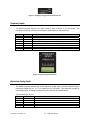
 Figure 10: Analog Output Connectors
Each analog output also features a slider switch located on the back of the controller. Each slider
features three positions: ±10V, ±20mA, and ±100mA. To change an outputs configuration, simply
move the slider for that channel to the desired setting. Analog output drive circuitry is protected
by a 0.5A circuit breaker labeled SIGNAL PWR. The circuit breaker is located on the rear panel.
Digital Inputs (Front Connectors)
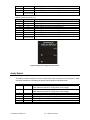
The RAPID controller features four, 8-pin digital input connectors on its front panel. The digital
inputs are sinking and therefore require voltage to be applied in order to indicate an ON. Each
connector provides for connecting two digital input signals as indicated below:
Name
DI-0+
DI-0PWR_1
Pin
1
2
3
COM_1
4
DI-1+
DI-1PWR_2
5
6
7
COM_2
8
Description
Positive signal connection for digital input 0
Negative (COM) signal connection for digital input 0
Positive excitation voltage (24V) out to sensor. See the
Power Selection section for configuration of this voltage.
Negative excitation voltage (COM) out to sensor. See the
Power Selection section for configuration of this voltage.
Positive signal connection for digital input 1
Negative (COM) signal connection for digital input 1
Positive excitation voltage (24V) out to sensor. See the
Power Selection section for configuration of this voltage.
Negative excitation voltage (COM) out to sensor. See the
Power Selection section for configuration of this voltage.
Figure 11: Digital Input Connector
© Wineman Technology, Inc.
3-7
RAPID User Manual
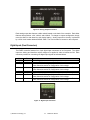
Excitation
Excitation
Excitation
Excitation