1
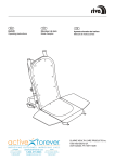
USER MANUAL
Moulder MO-300
Glimek AB
407326-11
Box 124, S-28064 Glimåkra Sweden
Tel. 044-44 900, Int 0046-44 44 900
Fax. 044-44 910, Int 0046-44 44 910
FOREWORD
CONTENTS
We should like to congratulate you on
your purchase of a first class moulder.
Manufactured by Glimek AB. The machine
has been developed so as to be simple to
use, maintain and service. To obtain the
maximum performance from the machine
it is important that it is used correctly and
that the instructions in the User Manual
are followed. The User Manual describes
the operations and adjustments that the
user can and should carry out so that the
machine can be used to the best
advantage. The operator is expected to
have a degree of experience in the use of
baking machinery. Keep this manual to
hand for when needed.
Funktions
Technical description
Delivery check
Installation
Controls
Before operating
Operating
Warning/Instructional signs
Post operation
Maintenance
Checks and adjustments
Specification
2
2
3
4
5
7
7
8
9
12
14
16
Appendix
INTENDED USES
The machine is intended to be used when shaping pieces of dough to their proper
shape.
GENERAL
SAFETY INSTRUCTIONS
This machine is constructed and built to be operated safely by both the user and operator. A variety of
protective and safety devices have been built into this machine. It is unsafe to operate this
machine without these safety devices both in place and properly functioning. It is a violation of the
accepted safety standards to bypass the recommended safety features.
It is recommended that the end user of this machine maintains the posted safety instructions, caution
labels and warning labels for the life of the machine. This maintenance includes but is not limited to the
legibility and placement of these instructions, caution and warning labels.
Cleaning of this machine should be done under all applicable lock-out / tag-out procedures and failure
to do so could result in personal injury and / or property damage.
It is strongly recommended that the user and operator become familiar with all the functions of this
machine and the handling of this machine by a thorough rewiew of this user manual, the instructions
and the warnings contained in this user manual and on the machine.
Only GLIMEK original parts should be used in the repairs of this machine so as to maintain the quality
of operation as intended.
Violations of the standards and operation procedures may be cause for the manufacturer to void any
warranty. In addition, the user shall assume all risks for damages to persons and / or property arising
out of the violation of any safety standards, violation of the recommended operation procedures and
damages to persons and property which may result from any and all unauthorized changes or
modifications to this machine.
THINK SAFETY.
1
FUNCTIONS & TECHNICAL DESCRIPTION
D
z
C
z
E
F
G
H
I J
z
z
B
A
z
z
z
z
z
z
z
M
N
Side view from the right
A
B
C
D
E
=
=
=
=
=
Drive motor/gear
Driv. roller(conv.belt)
Hopper
Cover for hopper
Rolling unit
F
G
H
I
J
=
=
=
=
=
Conveyor belt
Pressure board
Lateral lining
Drum
Collection tray
O
Inset picture, crosssection, rolling unit
M = Upper pair of rollers
N = Lower pair of rollers
O = Chain drag
The piece of dough falls down through the protective hood (D) between the side flaps of
the hopper(C). The distance between these can be adjusted using a handle on either
side; the position is indicated by a pointer. Further down to the upper pair of rollers (M).
The rolling out continues in the lower pair of rollers (N) whereupon the piece of dough
descends to the conveyor belt (F) and is carried along under the chain drag (O) where
the piece of dough is shaped into a roll. The conveyor belt transports the dough roll
under pressure board (G) and between the lateral linings (H) where the final length
and diameter of the piece of dough are determined. The prepared piece of dough is
delivered to the collection tray (J).
TECHNICAL DESCRIPTION
The moulder is driven by a geared motor. From the motor the power goes via a duplex
chain in the right-hand rear leg, to the driving rollers of the conveyor belt and from there
via a chain to the drive of the rolling unit. The centre chain of the rolling unit drive and
the chain, driving the four dough rollers, are provided with automatic chain tensioners,
so that smooth and safe running can be maintained. The dough rollers are
manufactured from polyethylene and each one has a spring-loaded scraper. The
distance between the dough rollers is set by means of a handle for each pair of rollers.
The tension of the conveyor belt can be adjusted by the belt drum with a screw on each
side. The driving roller can be adjusted on the right hand side in order to guide the path
of the belt.
cont.
2
TECHNICAL DESCRIPTION cont. DELIVERY CHECK
The input side of the chain drag is fixed in
a square section axle which is situated in a
holder on each side of the conveyer belt
and can be placed at three different heights
above the belt.
Standard lateral linings
The lateral linings are fixed in two
graduated axles and can be set separately
at the inlet- and exit ends.
Parallel adjustable lateral linings (alternative)
Left and right end rollers are fixed on two
rotational axles and can be set simultaneously using the handle. They can be set
separately at the infeed and outfeed ends.
The end rollers can be maneuvered from
either side of the machine by adjusting the
handles and hoods.
The pressure board hangs on two hinges and can be fold up to facilitate cleaning. The
height above the belt can be set separately at the inlet- and exit ends by means of two
graduated adjusting handles. The height of the pressure board can be maneuvered
from either side by turning the setting knob. The collection tray can be placed in two
different positions.
POST DELIVERY CHECK
The machine has been thoroughly checked, tested and test operated before it left the
manufacturer so that the equipment, operation and finish shall meet the high standards
demanded. Damage can occur during transportation so we ask you therefore to make a
post delivery check in accordance with the following:
Inspect the packaging and the machine for mechanical damage. If damage has
occurred, please contact the transport company.
Included with the machine:
A collecting tray and a carton, banded to the top of
the pressure board.
In the carton, the following are included:
4
off Castors
16 off Screws
16 off Plain washers
User manual
Documents
3
INSTALLATION
Setting castors in position
Lift up the back and front ends of the long moulder
with for example a pallet hoist. Take care with the
back end so that no electrical cables are caught up.
Put the castors in place and the four screws per
wheel.
Place the machine in position and secure it there by
locking all four wheels.
Put the collection tray in place.
Check the plate on the machine before connecting to
the electrical supply, to ensure that the voltage is
suitable.
Ensure that the safety systems are operational and that
no foreign substances are in or on the machine.
Ô
Correct direction of rotation
Start the machine for a short while. Check that the
conveyor belt goes in the right direction. Contact an
electrician if the machine is rotating in the wrong
direction.
4
CONTROLS
Start and stop buttons
The startbutton, 1 is green.
The stop button, 0 is red.
Setting of the sideflaps of the hopper
Ô
Ô
2
1
A handle is positioned on both sides for centering the
side flaps so that the pieces of dough fall down
centered between of the rollers. The dough can be
rolled out evenly on both sides.
Turn handle 1 inwards or outwards from either side.
The position set is indicated by a pointer 2.
Ô
1
Setting of upper and lower pair of rollers
The adjusting handle has a scale from 0 - 20, which
shows the relative distance between the pair of
rollers. Press on the centre of the handle and pull out
the handle when resetting.
The adjusting handle for the pair of rollers can be
positioned on either side of the machine. See page
14 for how to transfer.
Setting of chain drag
Ñ
Lift up the front protective cover.
The chain drag inlet end can be set to three different
heights and positions in relation to the conveyor belt.
Pull out the locking pin, (by the arrow) on both sides
and place the axle of the chain drag in the same
groove on both sides.
The rolled dough should come in easily under the
chain drag but not too near the roller.
cont
5
CONTROLS, cont.
Setting of the inlet- and the exit height of the
pressure board
The adjusting handle has a scale from 0 - 60 which
shows the relative distance to the conveyor belt.
The pressure board can be adjusted to different
heights in each respective end. Generally the exit
height should be greater than the inlet height.
The adjusting handles for the pressure board can be
situated on either side of the machine. See page 14
for how to transfer.
Ð
Setting of the standard lateral linings
The lateral linings on both sides are supplied with
graduated rulers for setting of the distance between
the lateral linings. The distance between the
markings is 10 mm.
Dist. betw. lateral linings
Setting
Min. 100 mm
10
Max. 660 mm
66
The lateral linings should be adjusted to the same
distance on both sides and should be parallel. Altering of a marking on the rulers changes the distance
between the lateral linings by 20 mm i.e. 10 mm on
each side.
Setting parallel adjustable lateral linings
End rollers on both sides are set simultaneously
using a handle.
The distance between the markings is 10 mm.
Dist. betw. lateral linings
Setting
Min. 100 mm
10
Max. 660 mm
66
Changing a marking on the graduated ruler will
change the distance between the lateral linings by 20
mm, 10 mm on each side.
They can be set separately at the infeed and outfeed
ends
6
BEFORE OPERATING
Cleaning of the machine
Wipe the whole machine with drying paper.
Especially important are the components which
come in contact with the dough.
Whenever the machine is cleaned the power should be
disconnected. The plug should be pulled out,
or when a fixed connection is used
the main power switch should be turned off.
Adjust the rollers, the chain drag, the pressure board
and the lateral linings. (See recommendations
below). Start the machine and run some pieces of
dough through the machine a few times until they are
no longer contaminated by the machine.
Ô
OPERATING
The incoming size of the dough as well as the finished dimensions should serve as a
guide when it comes to the settings on the machine. It is also important that the reshaping of the dough is done in gradual stages. The weight of the pieces of dough is the
criteria which decides the setting of the machine in the initial starting phase, but the final
adjustments can be made when the end result is seen.
The suggestions below can serve
as inlet values:
Weight of dough
Length
450 gr
230 mm
A= 11, B= 7, C= 17, D= 30
Lateral linings set to 23.
A
B
C
D
Weight of dough
Length
800 gr
250 mm
A= 12, B= 8, C= 19, D= 36
Lateral linings set to 25.
The chain drag is usually in the
lowest position.
cont
A = Upper pair of rollers
B = Lower pair of rollers
C = Pressure board, in
D = Pressure board, out
7
OPERATING, cont.
Run some pieces of dough through the machine
and check at the collecting tray that the shape and
appearance is correct.
Ô
Ó
Check continually during running that the pieces
of dough have the correct shape and appearance.
WARNING AND INSTRUCTIONAL SIGNS
Warning and/or instructional signs are affixed to
the machine to warn against incorrect actions
when operating the machine and to make the
operating easier. Always follow the directions on
these signs and urge all personnel in proximity to
the machine to do the same.
N.B. It is the responsibility of the owner/user
to see to it that warning and
instructional signs are in place and legible.
8
POST OPERATION daily
Whenever the machine is being cleaned it should be stationary
and the main power turned off; the plug should be
pulled out if no other direction are given.
Cleaning of hopper/cover for hopper
Pull the cover forward.
Scrape clean inside the hopper and on the cover with
a plastic scraper. Wipe with drying paper afterwards.
Push the cover back.
Cleaning of the rollers
Open the front protective cover and clean with a
brush around the scrapers.
Cleaning of the chain drag
Ñ
Push up the front protective cover. Remove the
locking pins.
cont
9
POST OPERATION, daily, cont.
Cleaning of the chain drag cont.
Lift up the chain drag.
Clean it in lukewarm water, dry it and replace it in
reverse order.
Cleaning of the pressure board and the lateral
linings
Extract the locking pins for the pressure board.
Ð
Raise the pressure board and place support pin in
the locking lug.
Í
Clean the pressure board with a plastic scraper.
Brush off the pressure board with a soft brush.
Scrape away any remnants of dough from the lateral
linings and wipe with a damp cloth.
10
POST OPERATION, daily, cont.
Cleaning of the conveyor belt.
When cleaning the conveyor belt the machine
must be running.
Ensure that no unauthorized persons
are in the vicinity.
Start the machine and hold a plastic scraper against
the belt (see diagram) until any remnants of dough
are removed.
Brush off the belt with a soft brush.
Lower the pressure board.
Ï
11
MAINTENANCE
EVERY THIRD MONTH
To tension the duplex chain
Loosen and remove the protective cover at the rear
of the machine.
Loosen and remove the chain guard.
The tension of the chain is correct if the chain can be
moved approx. 10 mm in the middle between the
chain sprockets (see arrows).
When needed, brush the chain with oil.
Î Í
Ó
Ô
The tension of the chain is adjusted by raising/
lowering the motor.
Loosen the four mounting bolts, (see arrows); two
are situated on the front and adjusted with the
adjusting screw which is situated in the beam in the
centre under the gear. Lock the adjusting screw with
the locking nut after finishing the adjustment.
N.B. Take care that the motor is horizontal after
adjustment and pull the four mounting bolts tight.
Reassemble the parts in reverse order.
12
MAINTENANCE, cont.
EVERY THIRD MONTH, cont.
Oiling the gears
Loosen and remove the protective cover at the
back of the machine. See page 12.
The oil level is checked by loosening the level
plug.
The level should be exactly at the holes lower
edge.
Filling of the oil is facilitated by using the filling
plug (see white arrow).
An oil exchange using mineral oil must be done
after 10,000 hours of operation.
Greasing the middle chain and the roller chain
When needed remove the adjusting handles (see
page 14). Loosen and remove the side cover.
The middle chain and the drive chain for the rolling
mill should be brushed with oil when needed.
13
Ï
CHECKS AND ADJUSTMENTS
Transferring the control handles
Loosen the lateral linings on both sides, in four
places.
Pull out the lateral linings to their outermost positions
on each side. Lower the pressure board so that it is
positioned directly on the conveyor belt.
The handle is now towards the zero (see arrow).
Loosen the centre pin with an "Allen key" and pull out
the handle.
Í
Loosen the screws, (see arrows), which hold the hub
and the drivingpin with an "Allen key".
Ð
Ò
Ñ
Loosen the hub and the drivingpin and place it on the
other side. Fit the driving pin into the slot of the axle.
Fasten the screws.
Í
Put the handle in place with the marking on the
handle toward the zero on the scale, (see arrow).
Pull the handle tight with the centre pin using an
"Allen key".
Readjust the pressure board and the lateral linings.
cont.
14
CHECKS AND ADJUSTMENTS, cont.
The belt of the conveyor
The tension of the belt is adjusted by tensioning or
loosening the adjusting screws on both sides. Adjust
the tension of the belt so that it is on the middle of
the drum.
If the belt is not running properly in the middle of the
driving roller, then the position of the roller should be
adjusted backwards/forwards. This adjustment is
done at the left side of the machine. First loosen the
nuts on the bearing holder. Tighten or loosen the
adjusting screw's cap nut (see arrow) until the belt is
running properly in the middle of the driving roller.
Finally retighten the nuts.
Motor protector and control fuse
As protection against overload a motor protector and
a control fuse are built-in. They are situated in the
electrical box by the left rear leg of the machine.
Ó
Ô
N.B. They should normally not be activated and if it
happens several times then the reason must be
determined.
The control fuse
The control fuse is an automatic fuse, which protects
the control system of the machine.
Loosen and remove the protective cover.
Loosen the four retaining screws and remove the lid
of the electrical box.
Ó
Ô
If the control fuse has been activated, the rocking
commutator points to the right (OFF). Reset the fuse
by pushing the rocker to the left (ON). Upper arrow.
Ð
Ï
The motor protector
If the motor protector has tripped: reset by pushing in
the black button. Lower arrow.
15
SPECIFICATION
Weight:
Electrical supply:
Electrical motor:
Noise level:
Gear wheel oil:
Chain oil:
385 kg
3-phase AC
1,1 kW
72 dBA
Loadway EP 220
Klüber oil 4UH 1500 or the equivalent
Take a note of the machine's serial number and other information.
Serial no.............................................
Delivery date.......................................
Supplier................................................................................................................................
..................................................................................................................................
16
APPENDIX 2
Sample table where different dough types, recipes and weights and
equivalent settings can be noted to simplify settings when later
production is current.
Dough type
Recipe
Dough weight Rollers upper/ Pr. board intake/ Lateral lining
exit
lower
17