1
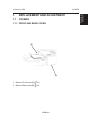
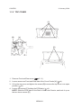
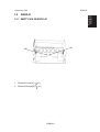
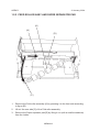
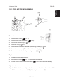
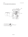
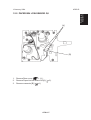
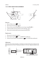
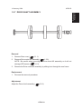
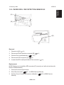
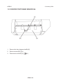
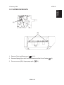
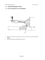
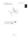
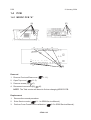
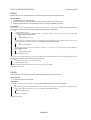
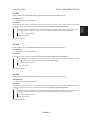
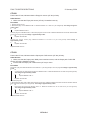
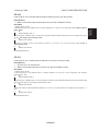
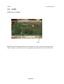
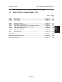
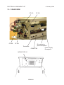
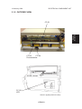
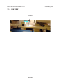
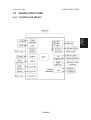
COVER FEEDER CF90
SERVICE MANUAL
January 12, 2004
Subject to change
Page intentionally blank
TABLE OF CONTENTS
1 REPLACEMENT AND ADJUSTMENT ............................... CF90-1-1
1.1 COVERS ........................................................................................ CF90-1-1
1.1.1 FRONT AND REAR COVER ................................................. CF90-1-1
1.1.2 TOP COVER .......................................................................... CF90-1-2
1.2 AREA D .......................................................................................... CF90-1-3
1.2.1 EMPTY BIN SENSOR Q1 ..................................................... CF90-1-3
1.2.2 FEED ROLLER ASSY AND PAPER SEPARATOR PAD ....... CF90-1-4
1.2.3 FEED MOTOR M1 ASSEMBLY ............................................. CF90-1-5
1.2.4 BIN HOME POSITION SENSOR Q2 ..................................... CF90-1-6
1.2.5 PAPER BIN LOW SENSOR Q5............................................. CF90-1-7
1.2.6 DRIVE MOTOR M2 ASSEMBLY ............................................ CF90-1-8
1.2.7 DRIVE SHAFT ASSEMBLY ................................................... CF90-1-9
1.2.8 PINCH ROLL SHAFT ASSEMBLY ...................................... CF90-1-10
1.2.9 PAPER PATH / DSD DETECTION SENSOR Q3 .................CF90-1-11
1.2.10 PAPER POSITIONING SENSOR Q4 ................................ CF90-1-12
1.2.11 UPPER PAPER PATH ....................................................... CF90-1-13
1.3 BIN EXTENSION PLATE ............................................................. CF90-1-14
1.3.1 BIN EXTENSION PLATE ASSEMBLY................................. CF90-1-14
1.3.2 BLOWER MOTOR M3 ........................................................ CF90-1-15
1.4 PCB .............................................................................................. CF90-1-16
1.4.1 MD3DC PCB ”A” .................................................................. CF90-1-16
2 TROUBLESHOOTING ........................................................ CF90-2-1
2.1 FAULT CODE DESCRIPTIONS ..................................................... CF90-2-1
2.2 LEDS .............................................................................................. CF90-2-8
3 DETAILED SECTION DESCRIPTION ................................ CF90-3-1
3.1 ELECTRICAL COMPONENT LIST ................................................ CF90-3-1
3.1.1 REAR VIEW .......................................................................... CF90-3-2
3.1.2 OUTFEED VIEW ................................................................... CF90-3-3
3.1.3 BIN VIEW .............................................................................. CF90-3-4
3.2 BOARD STRUCTURE ................................................................... CF90-3-5
3.2.1 CONTROLLER MD3DC ........................................................ CF90-3-5
3.3 COVER FEEDING PROCESS ....................................................... CF90-3-6
3.3.1 PRINCIPLE OF OPERATION ................................................ CF90-3-6
Inserting covers ......................................................................... CF90-3-6
I
12 January, 2004
Page intentionally blank
COVERS
1.
REPLACEMENT AND ADJUSTMENT
1.1
COVERS
1.1.1 FRONT AND REAR COVER
[B]
[A]
1. Remove Front cover [A] ( x1).
2. Remove Rear cover [B] ( x1).
CF90-1-1
Replacement
Adjustment
12 January, 2004
COVERS
12 January, 2004
1.1.2 TOP COVER
[C]
[B]
[A]
[D]
1. Remove Front and Rear cover (
2.1.1).
2. Loosen screws on Front and Rear side of the Cover Feeder [A] (
x4).
3. Lift up the top cover and tighten the screws [B] to secure the top cover in an open
position ( x2).
4. Loosen the screws [C] holding the PCB plate ( x4).
NOTE: Slide the PCB plate to the Rear of the Cover Feeder, and hook it up on
the two lower screws [D].
CF90-1-2
12 January, 2004
AREA D
Replacement
Adjustment
1.2
AREA D
1.2.1 EMPTY BIN SENSOR Q1
[A]
[B]
1.
Remove screw [A] (
2.
Remove Sensor [B] (
x1).
x1).
CF90-1-3
12 January, 2004
AREA D
1.2.2 FEED ROLLER ASSY AND PAPER SEPARATOR PAD
[A]
[B]
[D]
[C]
1.
Remove the Fold roller assembly [A] by pressing it to the front side according
to figure [B].
2.
Lift out the rear side [C] of the Fold roller assembly.
3.
Remove the Paper separator pad [D] by lifting it out (with a small screwdriver)
from the holder.
CF90-1-4
12 January, 2004
AREA D
Replacement
Adjustment
1.2.3 FEED MOTOR M1 ASSEMBLY
[D]
[C]
[A]
[B]
[E]
[F]
Removal
1.
Remove Rear cover (
1.1.1).
2.
Remove Feed roller assembly (
3.
Disconnect Connector [A] (
4.
Remove E-clip [B] (
5.
Remove Feed motor M1 assembly by removing screws [C] (
6.
Loosen the allen screw [D] to Roller clutch assembly (
7.
Remove the motor bracket by removing screws [E] (
1.2.2).
x1).
x1).
x3).
x1).
x3).
Replacement
1.
Reverse the removal procedure.
2.
Enter Service mode (
3.
Perform Cover Feeder motor calibration (
5.1.1 in SR90 Service Manual).
5.5 in SR90 Service Manual).
Adjustment
Adjust the Roller clutch assembly, so that the sensor activator is in the middle ± 0.5
mm of Bin home position sensor Q2 [F]. Adjust by loosen screw [D].
CF90-1-5
AREA D
12 January, 2004
1.2.4 BIN HOME POSITION SENSOR Q2
[B]
[A]
1.
Remove Rear cover (
1.1.1) .
2.
Remove Bin home position Sensor Q2 [A] (
3.
Remove Connector [B] (
x1).
CF90-1-6
x1).
12 January, 2004
AREA D
Replacement
Adjustment
1.2.5 PAPER BIN LOW SENSOR Q5
[A]
[B]
1.
Remove Rear cover (
1.1.1) .
2.
Remove Paper bin low sensor Q5 [A] (
3.
Remove connector [B] (
x2).
x1).
CF90-1-7
AREA D
12 January, 2004
1.2.6 DRIVE MOTOR M2 ASSEMBLY
[A]
[D]
[B]
[C]
Removal
1.1.1).
1.
Remove Rear cover (
2.
Disconnect Connector [A] (
3.
Remove Drive motor M2 assembly by removing screws [B] (
4.
Loosen the allen screw [C] to Drive clutch assembly (
5.
Remove the motor bracket by removing screws [D] (
x1).
x2).
x1).
x3).
Replacement
1.
Reverse the removal procedure.
2.
Enter Service mode (
3.
Perform Cover Feeder motor calibration (
5.1.1 in SR90 Service Manual).
5.5 in SR90 Service Manual).
Adjustment
Adjust the Drive clutch assembly, so that there is a play between the coupling on the
Drive shaft and the Clutch. The play should be 0.4 ± 0.3 mm. Adjust by loosen screw
[C].
0.4 ± 0.3 mm play between
the coupling and the clutch
CF90-1-8
12 January, 2004
AREA D
Replacement
Adjustment
1.2.7 DRIVE SHAFT ASSEMBLY
Removal
1.
Remove Rear cover (
2.
Remove Drive motor M2 assembly (
1.2.6).
NOTE: Be careful when removing the Drive motor M2 assembly, so it will not
damage LED sensor (
3.1.2).
3.
Remove the Drive motor M2 assembly, by sliding it out through the rear frame.
1.1.1).
Replacement
1.
Reverse the removal procedure.
Adjustment
Adjust the Drive clutch assembly (
1.2.6).
CF90-1-9
AREA D
12 January, 2004
1.2.8 PINCH ROLL SHAFT ASSEMBLY
1.
Remove the Pinch roll shaft assembly by pressing it to the rear side of the
Cover Feeder.
CF90-1-10
12 January, 2004
AREA D
Replacement
Adjustment
1.2.9 PAPER PATH / DSD DETECTION SENSOR Q3
[A]
[B]
[D]
[C]
Removal
x1).
1.
Remove nut [A] (
2.
Disconnect Photo transistor connector [B] (
3.
Remove Drive shaft assembly (
4.
Disconnect LED connector [C] (
5.
Loosen the LED nut [D] and slide off the connector (
x1).
1.2.7).
x1).
x1).
Replacement
NOTE: Make sure to install the LED connector [C] correctly, so it will not interfere with
the Drive shaft assembly.
1.
Reverse the removal procedure.
2.
Enter Service mode (
3.
Perform Cover Feeder DSD sensor calibration (
Manual).
5.1.1 in SR90 Service Manual).
CF90-1-11
5.5 in SR90 Service
AREA D
12 January, 2004
1.2.10PAPER POSITIONING SENSOR Q4
[C]
[B]
[A]
1.
Remove the Jam clearance baffle [A].
2.
Remove screw [B] (
3.
Disconnect connector [C] (
x1).
x1).
CF90-1-12
12 January, 2004
AREA D
Replacement
Adjustment
1.2.11UPPER PAPER PATH
[A]
[B]
1.
Remove Front and Rear cover (
2.1.1).
2.
Remove Spring [A] on the Front and Rear side of the Cover Feeder (
3.
Remove screws [B] to Upper paper path (
CF90-1-13
x2).
x2).
BIN EXTENSION PLATE
1.3
12 January, 2004
BIN EXTENSION PLATE
1.3.1 BIN EXTENSION PLATE ASSEMBLY
[B]
[A]
1.
Remove connector and ground wire [A] to Bin extension plate assembly
(
x2).
2.
Lift up the Bin extension plate [B] and remove it.
CF90-1-14
12 January, 2004
BIN EXTENSION PLATE
Replacement
Adjustment
1.3.2 BLOWER MOTOR M3
[B]
[A]
1.
Remove Bin extension plate assembly (
2.
Remove Ground cable [A] (
3.
Remove Blower motor M3 [B] (
x1).
x2)
CF90-1-15
1.3.1).
PCB
1.4
12 January, 2004
PCB
1.4.1 MD3DC PCB ”A”
[A]
[C]
J6
J3
J11
24 25 25 24
2 1
1 2
2 1
14 13
34
12
12
12
12
12 12
12
J1
J2
[B]
Removal
1
Remove Front and Rear cover (
2. Open Top cover (
1.1.2).
3. Remove screws [A] (
x7).
4. Disconnect connectors [B] (
1.1.1).
x5).
NOTE: The Total counter will be set to 0 when changing MD3DC PCB.
Replacement
1.
Reverse the removal procedure.
2.
Enter Service mode (
3.
Perform Cover Feeder motor calibration (
5.1.1 in SR90 Service Manual).
CF90-1-16
5.5 in SR90 Service Manual).
FAULT CODE DESCRIPTIONS
2.
TROUBLESHOOTING
2.1
FAULT CODE DESCRIPTIONS
CF-001 CF-M1
Feed motor cycle time out ............................................................. CF90-2-2
CF-002 CF-M1
Feed motor short circuit ................................................................ CF90-2-2
CF-003 CF-M1
Feed motor open circuit ................................................................ CF90-2-3
CF-004 CF-M2
Drive motor short circuit ............................................................... CF90-2-3
CF-005 CF-M2
Drive motor open circuit ................................................................ CF90-2-3
CF-008 CF-Q1
Empty bin sensor is faulty ............................................................. CF90-2-4
CF-009 CF-Q3
Paper path / DSD sensor is faulty ................................................. CF90-2-5
CF-010 CF-Q4
Paper positioning sensor is faulty ................................................ CF90-2-5
CF-011 CF-Q5
Paper bin low sensor is faulty ....................................................... CF90-2-6
CF-201 CF-Q3
Paper path / DSD sensor was Not blocked within timeout ......... CF90-2-7
CF-202 CF-Q3
Paper path / DSD sensor was Blocked exceeding timeout ......... CF90-2-7
CF-203 CF-Q4
Paper positioning sensor was Not blocked within timeout ........ CF90-2-7
CF-204 CF-Q4
Paper positioning sensor was Blocked exceeding timeout ....... CF90-2-8
CF-205
Double feed / Misfeed, Q3 DSD sensor ........................................ CF90-2-8
CF-401
Load covers, Q1 Empty bin sensor .............................................. CF90-2-8
CF-501
Load covers, Q5 paper bin low sensor ......................................... CF90-2-8
CF90-2-1
Troubleshooting
12 January, 2004
FAULT CODE DESCRIPTIONS
12 January, 2004
CF-001
Fault Code CF-001, indicates that the Feed motor (CF-M1) had a Cycle time out.
Initial Actions
Check fuse F2 on Transformer.
Enter the Service mode and select Feed motor (CF-M1) in check motors.
Make sure that the Bin home position sensor (CF-Q2) is installed correctly.
Procedure
Enter the Service mode and select Bin home position sensor (CF-Q2) in check sensors. The Bin home position sensor
indicates D:1 when the sensor is blocked and D:0 when the sensor is unblocked?
Y
N
1. Replace sensor CF-Q2.
2. Disconnect plug P11 from MD3DC PCB “A”. Measure between J11-4 and J11-6 (5V and ground). The
voltage is approximately 5 VDC.
Y
N
Replace MD3DC PCB “A”.
Connect plug P11 to MD3DC PCB “A”. Disconnect plug from sensor CF-Q2. Measure between the red wire
Q2 and the black wire Q2 (5V and ground). The voltage is approximately 5 VDC.
Y
N
Replace wire Harness.
Connect the sensor CF-Q2 plug. Measure between J11-5 and J11-6 (5V and ground). The voltage is
approximately 5 VDC.
Y
N
Replace wire Harness.
Replace MD3DC PCB “A”.
Turn motor CF-M1 in both directions by hand. You should be able to use about the same amount of force throughout the turn.
Are you able to turn the motor without using a lot of force?
Y
N
1. Make sure that there is no mechanical binding.
2. Replace motor CF-M1.
1. Make sure that the allen screw on the Bin motor roller clutch assy is tighten.
2. Replace motor CF-M1.
CF-002
Fault Code CF-002, indicates that the Feed motor (CF-M1) has a Short circuit.
Initial Actions
Check fuse F2 on Transformer.
Procedure
Disconnect the motor plug M1. Run the SDS again. Fault code CF-003 (Open circuit) is displayed?
Y
N
Disconnect plug P3 from MD3DC PCB “A”. Check wires for Short circuit across leads the orange wire M1 to
P3-7 (violet) and the violet wire M1 to P3-14 (orange). Is there Short circuit?
YN
Replace MD3DC PCB “A”.
Replace wire Harness.
Replace motor CF-M1.
CF90-2-2
12 January, 2004
FAULT CODE DESCRIPTIONS
CF-003
Fault Code CF-003, indicates that the Feed motor (CF-M1) has an Open circuit.
Initial Actions
Check fuse F2 on Transformer.
Disconnect the motor plug M1. Enter Service mode and start Feed motor (CF-M1) in check motors. Measure between the
orange wire M1 and the violet wire M1 (PWM 36V and ground). The voltage is approximately 36 VDC.
Y
N
Disconnect plug P3 from MD3DC PCB “A”. Measure between P3-7 and violet wire on the motor connector and be
tween P3-14 and the orange wire on the motor connector.Is there an open circuit in any of the wires.
Y
N
Replace MD3DC PCB “A”.
Replace wire Harness.
Replace motor CF-M1.
CF-004
Fault Code CF-004, indicates that the Drive motor (CF-M2) has a Short circuit.
Initial Actions
Check fuse F2 on Transformer.
Procedure
Disconnect the motor plug M2. Run the SDS again. Fault code CF-005 (Open circuit) is displayed?
Y
N
Disconnect plug P3 from MD3DC PCB “A”. Check wires for Short circuit across leads the orange wire M2 to
P3-6 (violet) and the violet wire M2 to P3-13 (orange). Is there Short circuit?
Y
N
Replace MD3DC PCB “A”.
Replace wire Harness.
Replace motor CF-M2.
CF-005
Fault Code CF-005, indicates that the Drive motor (CF-M2) has an Open circuit.
Initial Actions
Check fuse F2 on Transformer.
Procedure
Disconnect the motor plug M2. Enter Service mode and start Drive motor (CF-M2) in check motors. Measure between the
orange wire M2 and the violet wire M2 (PWM 36V and ground). The voltage is approximately 36 VDC.
Y
N
Disconnect plug P3 from MD3DC PCB “A”. Measure between P3-6 and violet wire on the motor connector and be
tween P3-13 and the orange wire on the motor connector.Is there an open circuit in any of the wires.
Y
N
Replace MD3DC PCB “A”.
Replace wire Harness.
Replace motor CF-M2.
CF90-2-3
Troubleshooting
Procedure
FAULT CODE DESCRIPTIONS
12 January, 2004
CF-008
Fault Code CF-008, indicates that the Empty bin sensor (CF-Q1) is faulty.
Initial Actions
Make sure that the Empty bin sensor (CF-Q1) is installed correctly.
Procedure
1. Replace sensor CF-Q1.
2. Disconnect plug P11 from MD3DC PCB “A”. Measure between J11-1 and J11-3 (5V and ground). The voltage is approximately 5 VDC.
Y
N
Replace MD3DC PCB “A”.
Connect plug P11 to MD3DC PCB “A”. Disconnect plug from sensor CF-Q1. Measure between the red wire Q1 and the black
wire Q1 (5V and ground). The voltage is approximately 5 VDC.
Y
N
Replace wire Harness.
Connect the sensor CF-Q1 plug. Measure between J11-2 and J11-3 (5V and ground). The voltage is
approximately 5 VDC.
Y
N
Replace wire Harness.
Replace MD3DC PCB “A”.
CF-009
Fault Code CF-009, indicates that the Paper path / DSD sensor (CF-Q3) is faulty.
Initial Actions
Make sure that the Paper path / DSD photo transistor sensor, and the Paper path / DSD LED
sensor (CF-Q3) is installed correctly.
Ensure that the Paper path / DSD sensor (CF-Q3) is clean.
Procedure
Disconnect plug J20. Measure between P20-2 and P20-1 (5V and ground) in the P-20 plug. The voltage is approximately
5 VDC.
Y
N
Connect plug J20. Disconnect plug P6 from MD3DC PCB “A”. Measure between the J6-4 and J6-9 (5V and ground).
The voltage is approximately 5?VDC.
Y
N
Replace MD3DC PCB “A”.
Replace wire Harness.
1. Connect plug J20.
2. Disconnect the Paper path / DSD photo transistor sensor plug. Measure between the white wire Photo transistor and the
black wire Photo transistor (5V and ground). The voltage is approximately 5 VDC.
Y
N
Disconnect plug P6 from MD3DC PCB “A”. Measure between the J6-10 and J6-22 (5V and ground).
The voltage is approximately 5 VDC.
Y
N
Replace MD3DC PCB “A”.
Replace wire Harness.
Replace MD3DC PCB “A”.
CF90-2-4
12 January, 2004
FAULT CODE DESCRIPTIONS
CF-010
Fault Code CF-010, indicates that the Paper positioning sensor (CF-Q4) is faulty.
Initial Actions
Make sure that the Paper positioning sensor (CF-Q4) is installed correctly.
1. Replace sensor CF-Q4.
2. Disconnect plug P11 from MD3DC PCB “A”. Measure between J11-7 and J11-9 (5V and ground). The voltage is approximately 5 VDC.
Y
N
Replace MD3DC PCB “A”.
Connect plug P11 to MD3DC PCB “A”. Disconnect plug J20. Measure between P20-6 and P20-8 (5V and ground) in the P20 plug. The voltage is approximately 5 VDC.
Y
N
Replace wire Harness.
Connect the sensor CF-Q4 plug. Measure between J11-8 and J11-9 (5V and ground). The voltage is
approximately 5 VDC.
Y
N
Replace wire Harness.
Replace MD3DC PCB “A”.
CF-011
Fault Code CF-011, indicates that the Paper bin low sensor (CF-Q5) is faulty.
Initial Actions
Check fuse F3 on Transformer.
Make sure that the Paper bin low sensor (CF-Q5) is installed correctly.
Procedure
1. Replace sensor CF-Q5.
2. Disconnect plug P11 from MD3DC PCB “A”. Measure between J11-10 and J11-12 (5V and ground). The voltage is
approximately 5 VDC.
Y
N
Replace MD3DC PCB “A”.
Connect plug P11 to MD3DC PCB “A”. Disconnect plug from sensor CF-Q5. Measure between the red wire Q5 and the black
wire Q5 (5V and ground). The voltage is approximately 5 VDC.
Y
N
Replace wire Harness.
Connect the sensor CF-Q5 plug. Measure between J11-11 and J11-12 (5V and ground). The voltage is approximately
VDC.
Y
N
Replace wire Harness.
Replace MD3DC PCB “A”.
CF90-2-5
5
Troubleshooting
Procedure
FAULT CODE DESCRIPTIONS
12 January, 2004
CF-201
Fault Code CF-201, indicates that during Run, the Paper path / DSD sensor (CF-Q3), was not blocked
within timeout after the start signal from the copier, was detected.
Initial Actions
Check fuse F2 on Transformer.
Make sure that the Paper path / DSD photo transistor sensor, and the Paper path / DSD LED
sensor (CF-Q3) is installed correctly.
Ensure that the Paper path / DSD sensor (CF-Q3) is clean.
Procedure
Enter the Service mode and select Paper path / DSD sensor (CF-Q3) in check sensors. Block, then unblock, the CF-Q3 with
a sheet of paper. The Paper path / DSD sensor (CF-Q3) sensor indicates D:0 when the sensor is blocked and D:1 when
the sensor is not blocked.
Y
N
Go to CF-009
1.
2.
3.
4.
Clean the feed rollers.
Make sure that the feed rollers are not worn out.
Check /clean the Paper separator pad.
Make sure that nothing interferes with the paper path in the Cover feeder.
CF-202
Fault Code CF-202, indicates that during Run, the Paper path / DSD sensor (CF-Q3), was blocked
exceeding timeout
Initial Actions
Check fuse F2 on Transformer.
Make sure that the Paper path / DSD photo transistor sensor, and the Paper path / DSD LED
sensor (CF-Q3) is installed correctly.
Ensure that the Paper path / DSD sensor (CF-Q3) is clean.
Procedure
Enter the Service mode and select Paper path / DSD sensor (CF-Q3) in check sensors. Block, then unblock, the CF-Q3 with
a sheet of paper. The Paper path / DSD sensor (CF-Q3) sensor indicates D:0 when the sensor is blocked and D:1 when
the sensor is not blocked.
Y
N
Go to CF-009
1. Clean the feed rollers.
2. Make sure that the Jam clearance baffle is installed correctly.
3. Make sure that nothing interferes with the paper path in the Cover feeder.
CF-203
Fault Code CF-203, indicates that during Run, the Paper positioning sensor (CF-Q4), was not blocked
within timeout.
Initial Actions
Check fuse F2 on Transformer.
Make sure that the Paper positioning sensor (CF-Q4) is installed correctly.
Ensure that the Paper positioning sensor (CF-Q4) is clean.
Procedure
Enter the Service mode and select Paper positioning sensor (CF-Q4) in check sensors. Block, then unblock, the CF-Q4 with
a sheet of paper. The Paper positioning sensor (CF-Q4) sensor indicates D:0 when the sensor is blocked and D:1 when
the sensor is not blocked.
Y
N
Go to CF-010
1. Clean the feed rollers.
2. Make sure that the Jam clearance baffle is installed correctly.
3. Make sure that nothing interferes with the paper path in the Cover feeder.
CF90-2-6
12 January, 2004
FAULT CODE DESCRIPTIONS
CF-204
Procedure
Enter the Service mode and select Paper infeed sensor (BM-Q1) in check sensors. Block, then unblock, the BM-Q1 with a
sheet of paper. The Paper infeed sensor (BM-Q1) sensor indicates D:0 when the sensor is blocked and D:1 when the
sensor is not blocked.
Y
N
Go to CF-010
1. Clean the Drive shaft tires.
2. Make sure that the Jam clearance baffle is installed correctly.
3. Make sure that nothing interferes with the paper path in the Cover feeder.
CF-205
Go to CF-009 Paper path / DSD sensor is faulty
CF-401
Go to CF-008 Empty bin sensor faulty.
CF-501
Go to CF-011 Paper bin low sensor faulty.
CF90-2-7
Troubleshooting
Fault Code CF-204, indicates that during Run, the Paper positioning sensor (CF-Q4), was blocked
exceeding timeout.
Initial Actions
Check fuse F2 on Transformer.
Make sure that the Paper positioning sensor (CF-Q4) is installed correctly.
Ensure that the Paper positioning sensor (CF-Q4) is clean.
12 January, 2004
LEDS
2.2
LEDS
PCB in Cover Feeder
D14
D14: Green LED flashes whenever information is sent or received on the Internal
CAN. If power is switched on but no operations are performed, Green LED is off.
CF90-2-8
ELECTRICAL COMPONENT LIST
3.
DETAILED SECTION DESCRIPTIONS
3.1
ELECTRICAL COMPONENT LIST
Page
Grid
code
CF-M1
CF-M2
CF-M3
Feed motor ........................................................................................ CF90-3-2 ......... A1
Drive motor ....................................................................................... CF90-3-2 ......... A1
Blower motor .................................................................................... CF90-3-4 ......... B1
CF-Q1
CF-Q2
CF-Q3
CF-Q3
CF-Q4
CF-Q5
Empty bin sensor ............................................................................. CF90-3-3
Bin home position sensor ............................................................... CF90-3-2
Paper path / DSD detection sensor (Phototransistor) ................... CF90-3-3
Paper path / DSD detection sensor (LED) ...................................... CF90-3-3
Paper positioning sensor ................................................................ CF90-3-3
Paper bin low sensor ....................................................................... CF90-3-2
PCB
MD3DC PCB ”A” ............................................................................... CF90-3-2 ......... D1
Terminator ........................................................................................................... CF90-3-2
Communication Cover Feeder ........................................................................... CF90-3-2
Bin extension plate Receptacle ......................................................................... CF90-3-2
Power supply Trimmer ....................................................................................... CF90-3-2
CF90-3-1
......... D1
........ G1
......... C1
......... C1
......... E1
......... F1
......... E8
......... D8
......... B2
......... B8
Detalied
description
12 January, 2004
ELECTRICAL COMPONENT LIST
12 January, 2004
3.1.1 REAR VIEW
CF-Q2
CF-M2
CF-M1
CF-Q5
Bin extension
plate Receptacle
Terminator
COM CF90
MD3DC PCB “A”
CF90-3-2
Power Supply
Receptacle
12 January, 2004
ELECTRICAL COMPONENT LIST
3.1.2 OUTFEED VIEW
Detalied
description
CF-Q1
CF-Q3
CF-Q4
Phototransistor
CF-Q3
LED
Shown in tipped position for clarify
CF90-3-3
12 January, 2004
ELECTRICAL COMPONENT LIST
3.1.3 BIN VIEW
CF-M3
CF90-3-4
12 January, 2004
3.2
BOARD STRUCTURE
BOARD STRUCTURE
Detalied
description
3.2.1 CONTROLLER MD3DC
CF90-3-5
COVER FEEDING PROCESS
3.3
12 January, 2004
COVER FEEDING PROCESS
3.3.1 PRINCIPLE OF OPERATION
Inserting covers
M1 Q3
M2
Q1
Q4
Cover on selected on the booklet maker UI.
Empty bin sensor (CF-Q1) detects that sheets are loaded. Feed motor (CF-M1)
reverses moving the bin to the up position and stops by bin home position sensor
(CF-Q2). The stack is now up against the feed roller. Blower motor (CF-M3) blows
separation air into the stack for a while.
If sheets has been run previously, the cover feeder is now in ready mode.
If sheets has just been loaded, feed motor (CF-M1) and drive motor (CF-M2) starts
and transports the sheet past sensor (CF-Q3). When paper positioning sensor
(CF-Q4) is activated, both motors stop (CF-M1 & M2). The cover feeder is now in
ready mode.
Copier sends a start signal.
Feed motor (CF-M1) and drive motor (CF-M2) starts*. First sensor (CF-Q3) becomes deactivated when first sheets leaves the sensor and activated again by the
second sheet. Then sensor (CF-Q4) becomes deactivated and activated the same
way. Both motors (CF-M1 & M2) stop when sensor (CF-Q4) becomes activated by
the second sheet. A sheet has been pulled and cover feeder is back in ready
mode.
*What separates the sheet distance from each other is that drive motor (CF-M2) is
faster but weaker than feed motor (CF-M1). When both motors drives the sheet it
runs on the feed motor’s (CF-M1) speed. But as soon as the first sheet’s trail edge
is release from motor (CF-M1), the sheet accelerates and runs on the drive motor’s (CF-M2) faster speed.
CF90-3-6