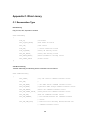
1
Rhio232 Serial I/O Manager User Manual Version 1.0.6 2015-09-11 1 Guide for the Rhio232 Version 1.0.6 Printed in Korea Copyright Copyright 2005~2015, Sena Technologies, Inc. All rights reserved. Sena Technologies reserves the right to make changes and improvements to its product without providing notice. Trademark Rhio™ is a trademark of Sena Technologies, Inc. Windows® is a registered trademark of Microsoft Corporation. Ethernet® is a registered trademark of XEROX Corporation. Notice to Users When a system failure may cause serious consequences, protecting life and property against such consequences with a backup system or safety device is essential. The user agrees that protection against consequences resulting from system failure is the user's responsibility. This device is not approved for life-support or medical systems. Changes or modifications to this device not explicitly approved by Sena Technologies will void the user's authority to operate this device. Technical Support Tel: (+82-2) 576-7362 Fax: (+82-2) 573-7710 E-Mail: [email protected] Website: http://www.senaindustrial.com 2 Revision History Revision Date Name Description V1.0.0 2005-05-21 D.H. Shin Initial Release V1.0.1 2005-08-08 D.H. Shin “Table 2-2. Terminal Block Assignment of the Rhio10 “ is added. V1.0.2 2005-11-02 D.H. Shin Typo errors corrected. V1.0.3 2005-11-08 J.S. Kim Operating and storage temperature updated. V1.0.4 2007-05-07 H.R. Zo Warranty added V1.0.5 2011-12-26 H.R. Zo Package does not contain CD-ROM V1.0.6 2015-09-11 KT Lee Change the contact information 3 is Table of Contents 1. Introduction ...................................................................................................................... 6 1.1 Overview ......................................................................................................................................... 6 1.2 Package Check List ........................................................................................................................ 6 1.3 Product Specification ...................................................................................................................... 7 2. Getting Started ................................................................................................................. 9 2.1 Panel Layout ................................................................................................................................... 9 2.2 Connecting the Hardware ............................................................................................................. 11 2.2.1 Setting up DIN Rail mount kit ............................................................................................. 11 2.2.2 Connecting the Power ........................................................................................................ 12 2.2.3 Connecting to the serial device .......................................................................................... 13 2.3 Rhio Manager Installation ............................................................................................................. 13 2.3.1 Rhio Manager Installation................................................................................................... 13 2.3.2 Basic configuration using Rhio Manager ............................................................................ 14 2.4 Restoring Factory Default ............................................................................................................. 15 3. I/O Setting and Application ........................................................................................... 16 3.1 I/O Monitoring and Control ............................................................................................................ 16 3.1.1 LED .................................................................................................................................... 16 3.1.2 Specifying monitoring interval ............................................................................................ 17 3.1.3 Monitoring I/O port ............................................................................................................. 17 3.1.4 Controlling digital output port.............................................................................................. 17 3.2 Digital Input Setting ....................................................................................................................... 18 3.2.1 Setting Enable/Disable ....................................................................................................... 18 3.3 Digital Output Port Setting ............................................................................................................. 19 3.3.1 Setting Enable/Disable ....................................................................................................... 19 3.3.2 Setting run condition .......................................................................................................... 20 3.3.3 Delay & Pulse Operation .................................................................................................... 21 3.3.4 Setting Power-out Post Recovery ...................................................................................... 21 3.4 ADC Input Port Setting .................................................................................................................. 21 3.4.1 Setting Reference .............................................................................................................. 22 3.4.2 Setting ADC Input Port ....................................................................................................... 22 3.5 I/O Port Connection ...................................................................................................................... 23 3.5.1 Digital Output Port .............................................................................................................. 23 3.5.2 Digital Input Port ................................................................................................................. 23 3.5.3 ADC Input Port ................................................................................................................... 24 4 4. Software Development & Application .......................................................................... 26 4.1 The Rhio Library............................................................................................................................ 26 4.1.1 Overview of the Rhio Library .............................................................................................. 26 4.1.2 Reference .......................................................................................................................... 26 4.2 Creating and demonstrating a sample program with Rhio library .................................................. 29 4.2.1 Program UI Configuration and their related classes ........................................................... 29 4.2.2 Processing ......................................................................................................................... 30 4.3 Rhio Communication Protocol ....................................................................................................... 33 4.3.1 Overview ............................................................................................................................ 33 4.3.2 ON/OFF Control ................................................................................................................. 35 4.3.3 Input/Output State .............................................................................................................. 38 4.3.4 Set/Run .............................................................................................................................. 38 4.3.5 Output Port Setting............................................................................................................. 39 4.3.6 ADC Input Port Setting ....................................................................................................... 42 4.3.7 Port Enable Setting ............................................................................................................ 43 4.3.8 Port Power-out Post Recovery Setting ............................................................................... 46 5. How to use the Rhio232 with Device Servers ............................................................. 48 5.1 Connections .................................................................................................................................. 48 5.2 Application..................................................................................................................................... 49 Appendix A. Connection ................................................................................................... 55 A.1 Serial Port Pin Outs ...................................................................................................................... 55 A.2 Serial Port Wiring Diagram ........................................................................................................... 56 Appendix B Troubleshooting ............................................................................................ 57 B.1 Power/LED Status Troubleshooting .............................................................................................. 57 B.2 Serial Console Troubleshooting .................................................................................................... 57 Appendix C. Rhio Linrary .................................................................................................. 58 C.1 Enumeration Type ........................................................................................................................ 58 C.2 Structure ....................................................................................................................................... 60 C.3 Function........................................................................................................................................ 61 Appendix D. Warranty ........................................................................................................ 74 D.1 GENERAL WARRANTY POLICY ................................................................................................. 74 D.2 LIMITATION OF LIABILITY........................................................................................................... 74 D.3 HARDWARE PRODUCT WARRANTY DETAILS ......................................................................... 75 D.4 SOFTWARE PRODUCT WARRANTY DETAILS .......................................................................... 76 D.5 THIRD-PARTY SOFTWARE PRODUCT WARRANTY DETAILS ................................................. 76 5 1. Introduction 1.1 Overview The Rhio232 is a Serial I/O Manager that enables Sena Device Servers to control and monitor I/O devices. It is designed to connect to a Sena Device Server through the RS232 interface. The Rhio232 supports 10 Digital Relay Output ports and has basic logic function capability such as AND, OR, NOT and Delay/Pulse along with the status of the input ports. The Rhio232 supports 12 optically isolated digital inputs for monitoring of the digital sensors. The Rhio232’s Analog ports support both level mode for data acquisition and switch mode for threshold detection. The data communication between host computers is done by event-driven method which is triggered when the status is changed. Users may probe, configure, test the Rhio232 system using Windows application, Rhio Manager and create their own Windows based application program by using MFC DLL library. The Rhio232, which can be used directly or with device servers, is designed to meet the requirements of various applications such as remote data acquisition system, distributed I/O system, industrial automation control/monitoring/metering. Please note that this manual assumes user knowledge of Internetworking protocols and serial communications. 1.2 Package Check List - Rhio232 external box - CAT5 cable - RJ45 to DB9 Female cable connector - DIN rail mount kit - Quick Start Guide 6 1.3 Product Specification Serial Interface Supports RS232 serial port, RJ45 connector Baud rate: 9,600/Flow control: None/Data: 8 bit/Stop: 1 bit -Number of channels: 12 -Input type: Voltage -Input circuitry: Optically isolated photo-coupler Digital Input -Input range: 0V ∼ ±24V OFF 0V ∼ ±1.2V, ON ±3.3V ∼ ±24V -Sampling rate: 20ms -Isolation voltage: 5KV - Number of channels: 10 - Output type: Relay Digital Output - Rated load: 3A/240VAC - Insulation resistance: 1000㏁ Min (DC500V) - Isolation voltage (coil and contact): 4KV - Reaction within 10ms - Number of channels: 4 - Effective resolution: 10-bit Analog Input - Input type: Voltage, Direct Coupling - Input range: 0V ∼ Aref (Analog reference voltage, 2~5V) - Sampling rate: 1000 samples/sec Protocol Management Software Support ARP, IP/ICMP, TCP telnet, DHCP client, PPPoE - Rhio Manager Windows Utility, Serial Console or Telnet - Windows MFC DLL library - I/O configuration, I/O status monitoring/control - Power, Link, Act Diagnostic LED - Digital Output, 1~10 - Digital Input, 1~12 - Analog Input, 1~4 Power Environmental 9V∼48VDC, Max. 5W - Operating temperature: 0℃ to 50℃ - Storage temperature: -20℃ to 66℃ - 90% Non-condensing 7 Physical properties Certification Warranty 137 x 111 x 58 (mm), 5.4 x 4.4 x 2.3 (in.) Weight: 730g FCC (A), CE, MIC 5-year limited warranty 8 2. Getting Started This chapter describes how to set up and configure the Rhio232 in the first place. - 2.1 Panel Layout explains the panel layout and LED indicators. - 2.2 Connecting the Hardware describes how to set up DIN rail mount kit and how to connect the power and the serial device to the Rhio232. Following items are required to get started. - DIN rail mount kit (included in the package). - CAT5 cable for configuration or connecting device server (included in the package). - RJ45 to DB9 Female connector for configuration or connecting device server (included in the package). 2.1 Panel Layout The Rhio232 has LED indicator lamps for status display. The lamps in the left hand side indicate the system power-on status, Serial Rx and Serial Tx for RS232 communication status. There are 10 lamps for displaying digital output status, 12 lamps for digital input status, and lamps for 4 analog port status. Table 2-1 shows the description of the indicator lamps of the Rhio232. Table 2-1. LED indicator lamps Lamps Function Turned on to Green if connected to 10 Base-T Ethernet Link network. 10Base-T Blink whenever there is any activities such as incoming Act or outgoing packets through the Rhio10 Ethernet port Staus Power Turned on to RED if power is supplied Digital Input DI 1 ~ DI 12 Turned on to GREEN if input status Digital Output DO 1 ~ DO 10 Turned on to GREEN if output status In Level Input mode, it is turned on to GREEN if the Analog Input AI 1 ~ AI 4 value is larger than 512. In Switch Input mode, it is turned on to GREEN if it is larger than threshold value. 9 Figure 2-1. The panel layout of the Rhio232 Table 2-2. Terminal Block Assignment of the Rhio232 AI1 AI2 AI3 AI4 DI1 DI2 DI3 DI4 DI5 DI6 DI7 DI8 DI9 DI10 DI11 DI12 1 3 5 7 9 11 13 15 17 19 21 23 25 27 29 31 33 35 2 4 6 8 10 12 14 16 18 20 22 24 26 28 30 32 34 36 • Power Input ( PWR_A , PWR_B ): (1,2) • Analog reference voltage ( Ref ) : (3) -It is analog reference voltage input block. Rhio represents voltage from 0 V to a reference voltage in 1,024 steps. A reference voltage may not exceed 5 V. For details, refer to Input Blocks assignment section 3.4 ADC Input Port Setting. • 5V Out : (4) - It is AVCC output block. User can input the power of devices. Ground is no.5,7,9 and 11 blocks. • Analog Input ( AI1 ~ AI4 ) : (5,6),(7,8),(9,10),(11,12) • Digital Input ( DI1 ~ DI12 ) : (13,14),(15,16),(17,18),(19,20),(21,22),(23,24), (25,26),(27,28),(29,30),(31,32),(33,34),(35,36) Note : 1. Each Input is composed of one pair of upper and lower blocks. 2. Except for the no.3 and 4 input blocks, users can connect the wire to the blocks without considering the polarity. DO1 DO2 DO3 DO4 DO5 DO6 DO7 DO8 DO9 DO10 Output A B A B A B A B A B A B A B A B A B A B Blocks 1 2 3 4 5 6 7 8 9 10 11 12 13 14 15 16 17 18 19 20 assignment Each Output is composed of one pair of A and B blocks as follows. • Digital Output ( DO1 ~ DO10 ) : (1,2), (3,4), (5,6), (7,8), (9,10), (11,12), (13,14), (15,16), (17,18), (19,20) 10 2.2 Connecting the Hardware 2.2.1 Setting up DIN Rail mount kit Users may use DIN rail mounting kit included in the package to install the Rhio232 on to the DIN rail. Figure 2-2. Dimension of DIN Rail mount kit and applicable DIN Rails Figure 2-3. Installing DIN Rail mount kit into DIN Rail 11 Figure 2-4. Setting up the Rhio232 to DIN Rail 2.2.2 Connecting the Power Supply the proper power according to the power specification of the Rhio232, i.e. 9V~48VDC, MAX. 5W. If the power is properly applied, [Power] indicator will maintain RED. Be sure not to use the cable longer than 3m for normal operation. Figure 2-5. Connecting the power to the Rhio232 12 2.2.3 Connecting to the serial device Connect the one end of the CAT5 cable to RS232 port of the Rhio232 and the other to host or device server. If connector type of host or device server is DB9, connect the other end using RJ45 to DB9 Female adaptor. If the cable is properly hooked up, the Rhio232 will have a valid connection to the device server(or host) by indicating: - [Serial Rx], [Serial Tx] green lamps continuously blink to indicate the incoming/outgoing data stream through serial port of the Rhio232 If any of the above does not happen, the Rhio232 is not properly connected to the RS232 communication. Note: User must configure serial parameters a host or device server in such a way that it should be same with the Rhio232's serial parameters. Serial parameters of the Rhio232 are as follows: 9600 Baud rate, Data bits 8, Parity None, Stop bits 1, No flow control Figure 2-6. Connecting host or device server to the Rhio232 2.3 Rhio Manager Installation Rhio Manager is a Windows Utility program for system configuration and I/O test of the Rhio232. 2.3.1 Rhio Manager Installation Users may install the Rhio Manager software by downloading at Sena web site http:// www.sena.com/support/downloads. If it is installed normally, then it will be placed on to the menu of [Start]->[Program]->[SENA]->[RHIO Manager]. The screen layout is shown in Figure 2-7. 13 Figure 2.7 Rhio Manager screen layout 2.3.2 Basic configuration using Rhio Manager Select Interface It specifies the communication method between the Rhio232 and Rhio Manager. Be sure to set it up as “Serial” mode. Quick Connect By using [Quick Connect], user can select the RS232 serial port that is connected to the Rhio232. I/O PORT CONTROL Users may monitor, control and configure the Rhio232’s I/O ports by clicking [I/O PORT CONTROL] button. 14 Figure 2.8 Quick connect dialog box 2.4 Restoring Factory Default Users may restore the Rhio232 parameters into factory default value by pressing factory reset switch on the hole of the Rhio232 side panel. They will have to put the sharp pin into the hole and press it for around 1 sec to reset the Rhio232. The Rhio232 will be rebooted after the operation. The following is the factory default value of the parameters. I/O Port status: Enable ADC Operation mode : Level Mode Power-out Post Recovery: Enable ADC Threshold value : 512 Output Port operation condition : None Run/Stop status : Run 15 3. I/O Setting and Application 3.1 I/O Monitoring and Control You can monitor, control and set I/O states by pressing the [I/O PORT CONTROL] button. Once [I/O PORT CONTROL] is invoked, Rhio Manager begins to monitor the I/O state by connecting to a serial port of the Rhio232 via a RS232 serial interface. 3.1.1 LED - ON : Red Icon - OFF : Blue Icon - Disable : Grey Icon - Condition ON/OFF : Green Icon - Macro: M - Delay ON: Red D - Delay OFF: Blue D - Pulse: P - Level Mode ADC Port : Green Figure 3-1 The I/O port Control screen 16 3.1.2 Specifying monitoring interval You can continue to monitor the I/O state of the Rhio232 at a specified time interval by setting [Setting Monitor Interval]. The valid value for monitoring intervals is any number between 2 and 10 seconds. In the specified time interval, Rhio Manager sends a state request command and receives a response from the Rhio232 and displays it on the screen. Figure 3-2 Setting Monitoring Interval 3.1.3 Monitoring I/O port Upon receiving a state request command from Rhio Manager, the Rhio232 returns information on the overall states of the digital input, analog input and digital output ports. - Digital Input Port shows the ON/OFF state of input. - In Level mode, ADC Input Port converts the analog value retrieved to a digital value in 1,024 steps and displays the converted value (“0000”-“1023”). - In Switch mode, ADC Input Port compares the input value to a specified threshold value and displays ON if it is higher and OFF if not. - Digital Output Port displays the ON/OFF state, operation condition for an output port, and standby state. 3.1.4 Controlling digital output port You can place your mouse over the Digital Output Port LED of Rhio Manager and left-click it to control ON/OFF state. - When the operation condition for a digital output port is not specified, the ON/OFF state for the port is toggled each time you left-click your mouse. 17 - When the operation condition is specified, the port is set to ON if it is met, and it is set to OFF and displayed as a standby state if not. - After output control is completed, the Rhio232 returns the states of all ports to the host computer. 3.2 Digital Input Setting The Rhio232 has 12 digital input ports. You can enable/disable each of these digital input ports with Rhio Manager or by issuing the commands specified in "Ch. 4 I/O Port Related Protocols". When setting the digital input with Rhio Manager, place your mouse cursor over the Digital Input LED on the I/O Port Control screen and right-click it to display the Setting window. 3.2.1 Setting Enable/Disable Figure 3-3 Setting digital input Digital input setting has two options: Enable and Disable. After selecting either of the options, press the [Setting] button to apply it in the system. A port cannot be set while it is operating in Run mode. Therefore, Rhio Manager sends a command that switches its mode to Setting mode first and then issues the set command when its operation is stopped. When set to Enable, Rhio Manger receives the ON/OFF state from the device connected to a digital input port and then displays it. When set to Disable, it displays Disable regardless of the ON/OFF state of the device connected to the input port. 18 3.3 Digital Output Port Setting The Rhio232 has 10 digital output ports. You can set each of these digital output ports with Rhio Manager or by issuing the commands specified in "Ch. 4 I/O Port Related Protocols". Place your mouse cursor over the Digital Output Port LED on the I/O Port Control screen and right-click it to display the Setting Output Port window. Figure 3-4 Setting digital output port window 3.3.1 Setting Enable/Disable Set a specified port to Enable/Disable by selecting the [Port Enable] and [Port Disable] check boxes. If it is set to Disable, the digital output port becomes fixed to OFF. 19 3.3.2 Setting run condition When the [Macro] check box is selected, you can enter a conditional expression and then use it to control operation of an output port. Enter the desired conditional expression in the [Macro] box. - Specify an operation condition for each output port. - An output port that has not been set is regarded as a port available for direct control. - The final value obtained from a logical operation on the listed expression becomes the state of an output port. - If the operation condition expression is cleared, a port becomes available for direct access. - Operation condition expressions can be specified as follows: 1) Port No. + Logic Expression (&,|) + Port No. 2) Logic Expression (!) + Port No. 3) Port No. + Logic Expression (&,|) + Logic Expression (!) + Port No. (Logical operator "!" can only be effective before the relevant port no.) 예) - Input #1 AND Input #2 I1&I2 - Input #1 OR Output #2 I1|O2 - The Inverse of Input #1 !I1 - Output #2 AND Output #3 AND the inverse of Output #4 O2&O3&!O4 - A single logical expression can contain up to 21 ports. - If a port is directly set to ON when its operation condition is not met, it goes into standby state. - A port goes into the ON state if its operation condition is met and into OFF and standby states if not. - If a port is directly set to OFF, it does not operate even if the operation condition is satisfied. 20 3.3.3 Delay & Pulse Operation If the [Use Delay/Pulse] check box is selected, the output port executes Delay and Pulse operation. The setting value for Delay and Pulse can be entered in 100 ms. - When Delay ON is selected, you can send the Output Port ON command to set an output port to ON after a specified delay time has passed. - When Delay OFF is selected, you can send the Output Port OFF command to set an output port to OFF after a specified delay time has passed. - When Pulse is selected, the port continues to toggle between ON and OFF according to the specified ON/OFF time. 3.3.4 Setting Power-out Post Recovery Power-out Post Recovery can be set for an output port using the [Setting power stoppage rehabitation] pane in the Setting window. - If it is enabled, the Rhio232 retains its output port states prior to power-out when power goes out and back on - If Power-out Post Recovery is enabled for an output port that has been set with an operation condition, the port becomes ON when power is restored if the operation condition is satisfied. - If it is disabled, the output port state becomes OFF when power goes out and back on. 3.4 ADC Input Port Setting The Rhio232 has 4 ADC input ports. You can set an ADC input port with Rhio Manager or by issuing commands via an I/O port protocol (refer to "Ch.4 I/O Port Related Protocols”). When using Rhio Manager, place the mouse cursor over the ADC Port LED on the [I/O Port Control] screen and right-click it to display the Setting ADC port windows as shown below: 21 Figure 3-5 Setting ADC Input Port 3.4.1 Setting Reference Specify a reference voltage for analog input data. Rhio represents voltage from 0 V to a reference voltage in 1,024 steps. A reference voltage may not exceed 5 V. Specify a reference voltage in the Reference list box. - Use Avcc: Specify Avcc (5V) as a reference voltage. - Use inside: Specify the internal reference voltage (2.56V) as a reference voltage. - Use Outside : Specify voltage issued to Aref as a reference voltage. 3.4.2 Setting ADC Input Port Analog Input Port has two modes: Level mode and Switch mode. - Level mode: Display voltage from 0 V to a reference voltage in 1,024 steps (“0000” ~ “1023”). - Switch mode: Compare input voltage level to threshold level setting and send a state change response when the input level is higher or lower than the threshold. An ADC input recognizes it is changed only when it is changed larger than 8 steps from the preconfigured threshold. 22 3.5 I/O Port Connection This section describes how to make a required connection with the digital output, digital input and ADC input port of the Rhio232 for the users’ devices. The length of cables used for I/O port connection should be less than 3 meters to ensure normal operation. 3.5.1 Digital Output Port All digital output ports are equipped with a status LED, which illuminates when a relay point is set to ON. An electric load can be connected as shown below by using OUTA1 and OUTB1 as driving switches. Load Figure 3-6 Connection of Digital Output Port 3.5.2 Digital Input Port A digital input system operates regardless of the ± polarity of the voltage and is insulated from the internal circuits in the system. It can be configured as shown in Figure 3-7 and has a status LED for each input, which illuminates when input voltage is issued. Note) Whilst it may operate in a voltage other than that specified (ON > ±3.2V / OFF < ±1.3V), be sure to use the specified voltage to ensure the stable operation. 23 Figure 3-7 Connection of Digital Input Port 3.5.3 ADC Input Port An ADC input port is a non-insulated input port. If possible, a circuit should be made using AVCC (+5V) voltage supplied from internal circuits. When operating in Switch mode, a threshold voltage should be specified. Input is set to ON and the ADC status LED is ON if the input voltage is higher than the specified threshold value. Conversely, input is set to OFF and the LED turns off when the input voltage is lower than the threshold. The ADC status LED operates only when it is set as Switch mode. 1) Connecting reference voltage (AREF) in analog input AREF can be set as either internal 2.56 V, internal AVCC or external AREF point. Internal input can be set using command. The external input can be set by splitting the AVCC voltage into R1 and R2 as shown below. The ideal resistance of split resistors R1 and R2 should be within the range of 1㏀ - 5㏀. Note) AREF voltage cannot be set to the value less than 2 V. Figure 3-8 Connecting Aref 24 2) When using an Analog Input Potentiometer An analog input operates in reference to input voltage and has an impedance of 100㏀. When using a Potentiometer as shown in Figure 3-9, an impedance in the range of 1㏀ - 5㏀ is ideal. When using an external signal source, lower impedance ensures stable operation against various noises. Note: Make sure that analog Input voltage does not exceed AREF voltage. Figure 3-9 Circuit connection when a Potentiometer is used 3) Connecting when a voltage higher than AVCC voltage is used For voltage input, the circuit should be split as shown in Figure 3-10. In case that the input wire is long or there is a strong noise nearby, it is recommended to have additional clamp diode in order to minimize the effect to other ADC channels although there is an internal clamp diode available. Figure 3-10 Circuit connection when a voltage higher than Avcc is used 25 4. Software Development & Application You can use the Rhio library to develop application software that is used to communicate with the Rhio232. The Rhio Library Files RHIO_Proc.dll, RHIO_Process.h You must link these two files in order to develop software using the Rhio library. Test Program A sample test program that has been developed using the Rhio library is provided to you in the form of source and setup files (RHIO_TEST_Setup.exe). The test program shows developers how to utilize the Rhio library more easily. 4.1 The Rhio Library 4.1.1 Overview of the Rhio Library The Rhio library is an MFC library that allows you to implement a communication protocol between Rhio and PC in a Windows environment. Since the Rhio library contains CSocket Class, it should be linked to a Microsoft Winsock component during program development. The RHIO_CommProcessCreate function must also be used to create Process Class for use of the library. 4.1.2 Reference For definition of enumeration(s), structure(s) and function(s), refer to RHIO_Process.h. 1) Enumeration (See Appendix C.1) Type Description EOnOffFlag ON/OFF - a flag indicating run state SendStateFlag A flag indicating transmission state of a command sent to Rhio ESetOutputFlag A flag related to enable/disable state when setting output port macro/delay/pulse EADCMode A flag specifying whether ADC is in Level mode or in Switch mode 26 2) Structure (See Appendix C.2) Structure Description SADCData ON/OFF state of each port SOnOffStateData ON/OFF state of all ports SSetOutput Output port configuration information SSetADC ADC configuration information SSetInput Input port configuration information SRHIOSetting All ports configuration information 3) Function (See Appendix C.3) Function RHIO_CommProcessCreate Description A function that creates Process Class that must be created for use of the library. RHIO_SockConnect Connect to RHIO via a socket (TCP/IP). RHIO_CommConnect Connect to RHIO via a serial port. RHIO_Close Disconnect from RHIO. RHIO_SndCmd_SetOnOff Send a command that controls ON/OFF. RHIO_SndCmd_GetOnOff Send a command that checks ON/OFF setting. RHIO_SndCmd_SetSettingMode Send a command that sets setting mode. RHIO_SndCmd_SetRunMode Send a command that sets run mode. RHIO_SndCmd_SetMACRO Send a command that sets macro for input port. RHIO_SndCmd_GetMACRO Send a command that checks macro setting for input port. RHIO_SndCmd_SetDelayPulse Send a command that sets delay/pulse for input port. RHIO_SndCmd_GetDelayPulse Send a command that checks delay/pulse setting for input port. RHIO_SndCmd_SetADC Send a command that sets the level of all ADC ports (1-4). RHIO_SndCmd_GetADC Send a command that checks the level of all ADC ports (1-4). RHIO_SndCmd_SetPortEnable Send a command that enables/disables all ports. 27 RHIO_SndCmd_GetPortEnable Send a command that checks enable/disable state of all ports. RHIO_SndCmd_SetPwrStopEnable Send a command that enables/disables power-out recovery for all ports. RHIO_SndCmd_GetPwrStopEnable Send a command that checks enable/disable state of power-out recovery for all input ports. RHIO_SndCmd_SetFactoryReset Send Rhio Factory Reset command. RHIO_SndCmd_SetSerial Send a command that sets Rhio serial number. RHIO_SndCmd_GetSerial Send a command that checks Rhio serial number. RHIO_SndCmd_GetFirmware Send a command that checks Rhio Firmware version. Retrieve corresponding data when an event RHIO_GetSettingData occurs such that a response on a check for setting is received from each port. Retrieve corresponding data when an event RHIO_GetOnOffData occurs such that responses from a change in and control of ON/OFF setting are received. 28 4.2 Creating and demonstrating a sample program with Rhio library The sample program (RHIO_TEST) is a dialog box based application that has been created with Microsoft Visual Studio .NET linked to Rhio library (RHIO_Proc.dll,RHIO_Process.h). 4.2.1 Program UI Configuration and their related classes Figure 4-1 Main Window of a Sample Program No. 1 Class CWEB_IO_TESTDlg Related Files WEB_IO_TESTDlg.h, WEB_IO_TESTDlg.cpp 2 CStateWnd StateWnd.h, StateWnd.cpp 3 COutputButton OutputButton.h, OutputButton.cpp 29 Figure 4-2 Setting Window of a Sample Program No. Class Related Files 1 CSettingDlg SettingDlg.h SettingDlg.cpp 4.2.2 Processing 4.2.2.1 Initializing Main window 1) Link the library and get the address of a required library function. CWEB_IO_TESTDlg::RHIODllLoad() 2) Initialize dialog items in Main window. CWEB_IO_TESTDlg::InitOutPutButton(); CWEB_IO_TESTDlg::InitInput(CPoint pntStart, int iWidth, int iHeight, int iTerm) 30 CWEB_IO_TESTDlg::InitSample(CPoint pntStart, int iWidth, int iHeight, int iTerm) CWEB_IO_TESTDlg::InitSelComm(); 3) Create Process Class. m_rhCreate(CWnd *pParentWnd) 4.2.2.2 Event Handling procedure 1) When an event occurs in the main window of the program: ① The Connect button is clicked on. CWEB_IO_TESTDlg::OnBnClickedButtonConnect() TCP Connection m_rhSockConnect (BYTE bAddr1, BYTE bAddr2, BYTE bAddr3, BYTE bAddr4, int iPort) Serial Connection m_rhCommConnect (int iPort) ② The Disconnect button is clicked on. CWEB_IO_TESTDlg::OnBnClickedButtonClose() ③ The Set Button is clicked on. CWEB_IO_TESTDlg::OnBnClickedButtonSetting() ④ The State View button is clicked on. CWEB_IO_TESTDlg::OnBnClickedButtonStateView() ⑤ The Output Port button is clicked on. COutputButton::OnBnClicked() 2) When an event occurs in the Setting window of the program: ① The Factory Reset button is clicked on. CSettingDlg::OnBnClickedButtonFactoryReset() ② The Set Mode button is clicked on. OnBnClickedButtonSetmode() ③ The Run Mode button is clicked on. CSettingDlg::OnBnClickedButtonRunMode() ④ The Monitor Serial button is clicked on. OnBnClickedButtonMonitorSerial() ⑤ The Set Serial button is clicked on. CSettingDlg::OnBnClickedButtonSetSerial() 31 ⑥ The Monitor Power Stop button is clicked on. CSettingDlg::OnBnClickedButtonMonitorPwrStop() ⑦ The Set Power Stop button is clicked on. CSettingDlg::OnBnClickedButtonSetPwrStop() ⑧ The Monitor Enable State of the Port button is clicked on. CSettingDlg::OnBnClickedButtonMonitorEnable() ⑨ The Enable Port button is clicked on. CSettingDlg::OnBnClickedButtonSetEnable() ⑩ The Monitor ADC Input button is clicked on. CSettingDlg::OnBnClickedButtonMonitorInput() ⑪ The Set ADC Input button is clicked on. CSettingDlg::OnBnClickedButtonSetInput() ⑫ The Check Delay/Pulse State button is clicked on. CSettingDlg::OnBnClickedButtonMonitorOutput2() ⑬ The Set Delay/Pulse button is clicked on. CSettingDlg::OnBnClickedButtonSetOutput2() ⑭ The Check Macro Setting button is clicked on. CSettingDlg::OnBnClickedButtonMonitorOutput() ⑮ The Set Macro button is clicked on. CSettingDlg::OnBnClickedButtonSetOutput() 3) When an event occurs in a Rhio device: CWEB_IO_TESTDlg::OnUpdateState(WPARAM wParam, LPARAM lParam) ① A port ON/OFF event occurs. m_rhGetOnOffData (SOnOffStateData &sOnOffData) ② Events other than a port ON/OFF occur. CSettingDlg::OnReceive(WPARAM wParam, LPARAM lParam) 32 4.3 Rhio Communication Protocol In this chapter, it covers how to send/receive the command/reply to/from Rhio device by using the Rhio communication protocol. 4.3.1 Overview You can use the Rhio communication protocol to set, control and monitor RHIO. 4.3.1.1 Command Block START LENGTH FUNCTION DATA 1 2 2 N Start of the The length from Command Command FUNCTION field Response FLAG Byte Size Block, Data 0x3A to DATA field LRC END (BCC) FLAG 2 2 XOR from LENGTH field to DATA ( “:” ) field Length calculation LRC calculation - START FLAG Start of the command block 0x3A ( “:” ) - LENGTH The length of the FUNCTION and DATA Fields - FUCTION Control/Set/Check/Status Command and Response Code - DATA Control/Set/Check/Status data 33 CR (0x0D) LF (0x0A) - LRC (BCC) It checks the Error of the command block. The value by 1 byte XOR from LENGTH field to DATA field - END FLAG CR+LF ( 0x0D+0x0A ) -. The data of LENGTH and LRC is expressed as follows. Each 4-bit nibble (upper 4-bit nibble and lower 4-bit nibble) is expressed as 1 Byte data. The 1-byte conversion of the 4-bit data is as follows. 0x0 ~ 0x9 0x30 ~ 0x39, 0xA ~ 0xF 0x41 ~ 0x46 If the Rhio receives the data converted, then it converts it to original by inverse. -. The timeout from the start of the frame to the time when it receives LF is 5 sec. -. Rhio will discard the command if there is any error in the command received (BCC Error or Time Out) and will wait for the next command (Users have to write a code so that it will have to wait at least 5 sec if there is no response from Rhio after sending the command.) * An Example of the LRC calculation is as follows : XOR from Start Flag field to the Data Field use the following as an example : (3A) (30 33) (30 33) (30) (30 41) (0D 0A) Do the following : ((((3A xor 30) xor 33) xor 30) xor 33) xor 30 = 0A 0A gets translated as 0 and A, the byte conversion, which is as follows: 0x0 ~ 0x9 gets converted as 0 and A, the byte conversion, which is as follows : 0x0 ~ 0x9 gets converted to 0x30 ~ 0x39 0xA ~ 0xF gets converted to 0x41 ~ 0x46 In the case of above 0 =30 and A = 41, thus the LRC is 30 41, as shown above. 4.3.1.2 NAK Response - NAK Response condition -. When there is Data BCC Error when receiving the command -. When the command data is not completed within 1 sec after it is started (Time out) -. When the length of the Data frame is not same as the one in the command (Frame Length error) 34 - NAK Response START LRC END (BCC) FLAG 2 2 LENGTH FUNCTION DATA 1 2 2 3 Start of the The length from Response NAK XOR Command FUNCTION field “00” Data LENGTH 0x30,0x30 “NAK” field to DATA 0x4E, field FLAG Byte Size Block, 0x3A to DATA field ( “:” ) from CR (0x0D) LF (0x0A) 0x41, 0x4B HOST RHIO Command Send Response if it receives the correct command set Send NAK Response (BCC Error or Timer out or Length calculation error) -. Users have to write code to send the command again or display NAK status if the program receives NAK Response. * NOTE: In the following descriptions, each port is indicated as below: - Input Port: I1 - I12 - ADC Input: A1 - A4 (Level Input and Switch Input modes) - Output Port: O1 - O10 4.3.2 ON/OFF Control 4.3.2.1 ON/OFF Control Command Command Byte Size Data Remark 2 “01” ( 0x30, 0x31 ) 10-point output masking and Send output points to set ON/OFF control data ON/OFF in a batch. ON/OFF control 35 - Data MASK Data Data Separator ON/OFF Data Data Order 1 - 10 11 12-21 Port No. 1 - 10 - 1-10 0x2C ( “,” ) Control: 0x31 Data Content ON: 0x31 separates MASK Non-control: 0x30 OFF: 0x30 from ON/OFF. MASK and ON/OFF Data correspond to one port per byte for each port in sequence. - Port location by Data Order Data 1 2 3 4 5 6 7 8 9 10 Order 12 13 14 15 16 17 18 19 20 21 Port O1 O2 O3 O4 O5 O6 O7 O8 O9 O10 4.3.2.2 Response for ON/OFF Control Response Data 2 52 Byte Size “02” ( 0x30, 0x32 ) input/output overall state - Remark ON/OFF state data for Send state of input/output ADC Level 4, points in a batch. Input 12 Point and Output 10 Point. Data Field Control State Data Port Order 1 - Data Content 0x30: Normal Control, 0x31: No Run Mode, 0x39: Abnormal Control 0x30: OFF, ADC Input 2-6 A1 0x31: ON (Switch Input), 0x39: Level Mode LEVEL 7 - Field Separator 0x2C ( “,” ) 36 “0000”-”1023”: Level 0x30: OFF, 8-12 A2 0x31: ON (Switch Input), 0x39: Level Mode 13 - A3 0x31: ON (Switch Input), 0x39: Level Mode 19 - A4 0x31: ON (Switch Input), 0x39: Level Mode Input State “0000”-”1023”: Level Field Separator 0x2C ( “,” ) 0x30: OFF, 20-24 Level Field Separator 0x2C ( “,” ) 0x30: OFF, 14-18 “0000”-”1023”: 25 - Field Separator 0x2C ( “,” ) 26-29 I1-I4 0x30: OFF, 0x31: ON 30 - Field Separator 0x2C ( “,” ) 31-34 I5-I8 0x30: OFF, 0x31: ON 35 - Field Separator 0x2C ( “,” ) 36-39 I9-I12 0x30: OFF, 0x31: ON 40 - Field Separator 0x2C ( “,” ) “0000”-”1023”: Level 0x30: OFF, 0x31: ON, 0x32: Wait for a conditional 41-44 O1-O4 execution, 0x33: Wait for Delay ON, 0x34: Wait for Delay OFF, 0x35: Run PULSE 45 - Field Separator 0x2C ( “,” ) 0x30: OFF, 0x31: ON, 0x32: Wait for a conditional Output State 46-49 O5-O8 execution, 0x33: Wait for Delay ON, 0x34: Wait for Delay OFF, 0x35: Run PULSE 50 - Field Separator 0x2C ( “,” ) 0x30: OFF, 0x31: ON, 0x32: Wait for a conditional 51,52 O9, execution O10 0x33: Wait for Delay ON, 0x34: Wait for Delay OFF, 0x35: Run PULSE - Indication that the system is standby when conditional execution for output port, pulse/delay operations are active (with ON command). 37 4.3.3 Input/Output State 4.3.3.1 I/O State Request Command Command Data 2 1 Byte Size “03” Remark 0x30: Fixed to a ( 0x30, 0x33 ) dummy value State Request 4.3.3.2 Response for I/O State Request Command - Identical with ON/OFF control response. - Sent even if the state of input port or ADC (in Switch Input mode) has been changed (based on a threshold voltage). A change of input state is recognized when the input value changed is maintained for 15 ms. - In case of state response, the control state field returns 0x30 in Run mode and 0x31 in Setting mode. 4.3.4 Set/Run 4.3.4.1 Set/Run Command Byte Size Command Data Remark 2 1 “04” 0x30: Set Switch between Set ( 0x30, 0x34 ) 0x31: Run and Run Modes. Set/Run - The Rhio232 returns a state response once after set command is received. It does not return any state response until it receives run command even if it is switched to Setting mode. - When setting output port, ADC input port, Port Enable, Port Power-out Recovery or serial number, send set command first to switch it to Setting mode. (Check command is working in both Setting and Run mode.) - Once each setting is completed, send run command to switch it to Run mode. 38 - When a run command is received, it returns a state response once and continues with the operation paused. 4.3.4.2 Response for Set/Run command - Same as "4.3.2.2 Response for ON/OFF control". - In Setting mode, the Rhio232 returns a response once and it does not respond until run command is received. - The control state field of the state response, the Rhio232 returns 0x31 in Setting mode and 0x30 in Run mode. 4.3.5 Output Port Setting 4.3.5.1 Set Output Port Command Command Byte Remark 2 2 “05” Port 0x30: Clear run condition Setting Set the attribute of ( 0x30, No. 0x31: Set run condition Data each output port. 0x35 ) “01” 0x32: Clear Delay or Pulse (Max. (When cleared, the Set output ~ 0x33: Set Delay/Pulse 106 setting data is 0x30 port. “10” 0x39: Clear all settings bytes) in 1 byte.) Size - Data 1 N A setting can be done only in Setting mode. Users can set repeated run condition, pulse or delay. When a port is set for repeated actions, run condition set up has a priority, which means it is executed first. A setting can be cleared by mode, or the entire setting can be cleared as well. When cleared, data setting becomes 0x30 in 1 byte. 1) Set run condition. It sets the run condition for the output port specified. (It is run only when an output port is ON and will set the port as OFF when it is configured as such.) - Input/Output port state + a conditional operator + Input/Output port state (AND/OR) 39 - A conditional operator + Input/Output port state (NOT) - AND => &, OR => |, NOT => ! - A conditional expression only takes the form of a single expression with AND, OR, NOT. Eg. AND operation of Input #1 and Input #2 : I1 & I2 OR operation of Output #3 and Input #1 - : O3 | I1 AND operation of the inversed Input #10 and Output #10 : !I10 & O10 Inverse operation of Input #1 : !I1 The number of points that can be specified for run condition per 1 output point in setting data must be less than 21 points. Eg. I1&I2&I3|I4|!I5|I6&I7&I8&I9&I10|!I11|I12| O2|O3|O4|O5|O6|O7|O8|O9|O10 - An output port to be set should not be included in run condition. Eg. When setting O1, it should not be included in its run condition expression. 2) Set Delay/Pulse. - It specifies the output to toggle between ON/OFF at a given time or repeatedly. (Delay ON and Pulse are enabled with ON control command and disabled with OFF control. Delay OFF is enabled with OFF control.) - Setting Data Setting Data (time) ON Time OFF Time Byte Size 5 5 Run Setting “00000”-“50000” “00000”-“50000” A setting can be specified in 100 ms and allowed up to 500 sec. Eg. ON Time OFF Time Remark “00000” “00000” No Delay/Pulse “00001” “00000” ON after 100 ms delay “00020” “00000” ON after 2 sec delay “50000” “00000” ON after 5,000 sec delay “00000” “00001” OFF after 100 ms delay 40 “00000” “00020” OFF after 2 sec delay “00000” “50000” OFF after 5,000 sec delay “00001” “00001” Repeat 100 ms ON and 100 ms OFF. “00020” “00020” Repeat 2 sec ON and 2 sec OFF. “50000” “50000” “00010” “00030” Repeat 1 sec ON and 3 sec OFF. “00300” “00150” Repeat 30 sec ON and 15 sec OFF. Repeat 5,000 sec ON and 5,000 sec OFF. 4.3.5.2 Response for Set Output Port command Response Byte Data 2 Size 1 “06” ( 0x30, Setting 0x36 ) Flag Return setting. - Remark 2 1 N Port 0x30: Clear run condition No. 0x31: Set run condition “01” 0x32: Clear Delay/Pulse - 0x33: Set Delay/Pulse “10” 0x39: Clear all settings Setting Data Return the setting of an output port. Setting Flag 0x30: Set OK 0x39: Set NG 0x31: Not in Setting mode (when in Run mode) 0x32: Unspecified (If the user attempts to clear in unspecified state, it will return 0x32.) (When it is in unspecified state, the setting data is 0x30 in 1 byte.) - When setting is cleared, the setting data is 0x30 in 1 byte. 4.3.5.3 Check Output Port Setting Command Command Byte Size 2 “07” ( 0x30, 0x37 ) Check setting. Data 2 1 0x31: Port No. “01” - “10” Remark Check the condition setting. 0x33: Check Delay/Pulse setting 41 run Check the attribute the of each output port. 4.3.5.4 Response for Check Output Port Setting command - Same as "4.3.5.2 Response for Set Output Port command". 4.3.6 ADC Input Port Setting 4.3.6.1 Set ADC Input Port Command Command Data 2 16 Byte Size Remark Set the threshold “08” ( 0x30, 0x38 ) Set ADC. level value for an Set it to a 10-bit ADC input ADC port. level value. ( “0000”-”1023”) X 4 - A threshold value is set for all ADC inputs in Switch Input mode. - When an input change is measured, only changes beyond the range of +8 - -8 are recognized as an input change (based on the threshold level). It is determined as ON when an input voltage is more than the threshold level by 8 or more and OFF when an input voltage is less than the threshold level by 8 or more. (When the threshold level is above 1015, a change between 1015-1023 is determined as ON. When it is set to less than 8, a change between 8-0 is determined as OFF.) ADC Input No. 1 2 3 4 Settings “0000”-”1023” “0000”-”1023” “0000”-”1023” “0000”-”1023” 4.3.6.2 Response for Set ADC Input Port command Byte Size Response Data 2 17 “09” Remark The threshold level ( 0x30, 0x39 ) Setting Return the FLAG ( “0000”-”1023”) X 4 ADC setting. 42 for input ADC port - Setting Flag 0x30: Set OK 0x31: Not in Setting mode (in Run mode) 0x39: Set NG 4.3.6.3 Check ADC Input Port Setting Command Command Data 2 1 Byte Size Remark “10” Check the ( 0x31, 0x30 ) 0x30: Fixed to a dummy threshold level Check the ADC value value of an input setting ADC port. 4.3.6.4 Response for Check ADC Input Port Setting command - Same as "4.3.6.2 Response for Set Port command". - The setting field is always OK (0x30). - The factory default value in Level Input mode is set to "0000". 4.3.7 Port Enable Setting 4.3.7.1 Set Port Enable command Byte Size Command Data 2 34 Remark “11” ( 0x31, 0x31 ) Port Enable/Disable setting data Set to Enable. - Data Field ADC Port Data Order Port 1 A1 2 A2 0x31: Level Input mode 3 A3 0x32: Switch Input mode 4 A4 43 Data Content Set all ports to Enable/Disable. 5 Field Separator 0x2C ( “,” ) - 0x30: AVcc ( Vcc 5V ) -> default ADC Reference 6 0x31: Internal ( 2.56V ) - 0x32: External ( 2-4.5V ) Setting 7 - Field Separator 0x2C ( “,” ) 8-11 I1-I4 0x31: Enable, 0x32: Disable 12 - Field Separator 0x2C ( “,” ) 13-16 I5-I8 0x31: Enable, 0x32: Disable 17 - Field Separator 0x2C ( “,” ) 18-21 I9-I12 0x31: Enable, 0x32: Disable 22 - Field Separator 0x2C ( “,” ) 23-26 O1-O4 0x31: Enable, 0x32: Disable 27 - Field Separator 0x2C ( “,” ) 28-31 O5-O8 0x31: Enable, 0x32: Disable 32 - Field Separator 0x2C ( “,” ) 33,34 O9, O10 0x31: Enable, 0x32: Disable Input Port Output State All I/O ports are initially set to Enable (including Factory Reset). All ADC ports are initially set to Level Input mode (including Factory Reset). 4.3.7.2 Response for Set Port Enable command Response Data 2 35 Byte Size Remark “12” ( 0x31, 0x32 ) Port Enable/Disable Return the Enable setting data Return all port Enable/Disable setting. - Data Field Data Order Port Data Content 0x30: Normal Enable, Setting 1 - 0x31: Not in Setting mode 0x39: Abnormal Enable 44 settings. 2 A1 3 A2 4 A3 5 A4 6 - 0x30: Avcc ( Vcc 5V ) -> default 0x31: Internal ( 2.56V ) ADC Port ADC Reference Setting 0x32: External ( 2V-4.5V ) Field Separator 0x2C ( “,” ) 0x30: Avcc ( Vcc 5V ) -> default 7 - 0x31: Internal ( 2.56V ) 0x32: External ( 2V-4.5V ) 9-12 I1-I4 0x31: Enable, 0x32: Disable 13 - Field Separator 0x2C ( “,” ) 14-17 I5-I8 0x31: Enable, 0x32: Disable 18 - Field Separator 0x2C ( “,” ) 19-22 I9-I12 0x31: Enable, 0x32: Disable 23 - Field Separator 0x2C ( “,” ) 24-27 O1-O4 0x31: Enable, 0x32: Disable 28 - Field Separator 0x2C ( “,” ) 29-32 O5-O8 0x31: Enable, 0x32: Disable 33 - Field Separator 0x2C ( “,” ) 34,35 O9, O10 0x31: Enable, 0x32: Disable Input Port Output State 4.3.7.3 Check Port Enable Setting command Byte Size Command Data 2 1 “13” ( 0x31, 0x33 ) 0x30: Fixed to a dummy Check the Enable value setting. 4.3.7.4 Response for Check Port Enable Setting command - Same as "4.3.7.2 Response for Set Port Enable command". - The setting field returns Normal (0x30) when it returns. - The initial value is set to Enable for all ports at the time of shipment. (ADC is set to Level Input mode.) 45 Remark Check all port Enable/Disable setting. 4.3.8 Port Power-out Post Recovery Setting 4.3.8.1 Set Port Power-out Post Recovery command Byte Size Command Data 2 12 Remark “14” Set Power-out ( 0x31, 0x34 ) Set Power-out Post Recovery to The Port Power-out Post Post Recovery to Recovery setting data Enable/Disable for an output port Enable/Disable. - Data Field Data Order Port 1-4 O1-O4 0x31: Enable, 0x32: Disable 5 - Field Separator 0x2C ( “,” ) 6-9 O5-O8 0x31: Enable, 0x32: Disable 10 - Field Separator 0x2C ( “,” ) 11, 12 O9, O10 0x31: Enable, 0x32: Disable Output State Data Content 4.3.8.2 Response for Set Port Power-out Post Recovery command Byte Size Response Data 2 13 Remark “15” Return the ( 0x31, 0x35 ) Return the Power-out The Port Power-out Post Recovery setting data Post Recovery setting. - Data Order Port Data Content 0x30: Set OK, Setting 1 Recovery setting for an output port. Data Field Power-out Post - 0x31: Not in Setting mode, 0x39: Set NG 46 Output State 2-5 O1-O4 0x31: Enable, 0x32: Disable 6 - Field Separator 0x2C ( “,” ) 7-10 O5-O8 0x31: Enable, 0x32: Disable 11 - Field Separator 0x2C ( “,” ) 12, 13 O9, O10 0x31: Enable, 0x32: Disable 4.3.8.3 Check Port Power-out Post Recovery Setting command Byte Size Command Data 2 1 Remark “16” ( 0x31, 0x36 ) Check the Power- 0x30: Fixed to a dummy value out Recovery Check the Powerout Recovery setting for all ports. setting. 4.3.8.4 Response for Check Port Power-out Recovery Setting command - Same as "4.3.8.2 Response for Set Port Power-out Recovery command". - The setting field returns Normal (0x30) when it returns. The initial value is set to Enable for all ports at the time of shipment. 47 5. How to use the Rhio232 with Device Servers The Rhio232 is a serial I/O manager that enables device servers to monitor and control I/O devices. It is designed to connect to a device server through the RS232 interface. The following is the typical way to use the Rhio232 with Sena device servers for remote I/O management application. - Connection by TCP socket program using Rhio Library: Sena device server + Rhio232 - Connection by Serial program (COM port) using Rhio Library: Serial/IP COM Port Redirector + Sena device server + Rhio232 Please refer to the tips_serial_ip_with_sena_ds-v1.0.0.pdf or Serial/IP User Manual for detailed information on the Serial/IP software. Users may get the corresponding material from http://www.sena.com/support/downloads/. This chapter covers how to connect the Rhio232 with the device server and the application configuration. 5.1 Connections The Rhio232 is connected to the serial device server through RS232 serial port and its connector type is RJ45. Users should use RJ45-DB9 female straight adapter in the package in order to connect the Rhio232 to the Sena device servers that has DB9 serial port, i.e. LS100, PS100. Users may directly use CAT5 straight cable to connect it to the Super series or STS series models that have RJ45 serial port. Table 5-1 shows the summary of the connections between Sena device servers and the Rhio232. 48 Table 5-1. Connections with the Sena device servers and the Rhio232 Sena device servers Connection Rhio232 DB9: RJ45-DB9 female straight RJ45: adapter + CAT5 straight cable eg. LS100, LS100W, PS100/200/400/110/410/810, SS100 RJ45: CAT5 straight cable eg. SS110/400/800 STS800/1600 5.2 Application This chapter covers how to test the Rhio232 with the Sena’s 8-port device server, SS800 by using Serial/IP software. The following is the units required to test and the corresponding configurations for each module. 49 Rhio232 and SS800 Serial/IP COM Port Redirector software Rhio Manager software Two CAT5 straight cable (One for the network connection of the SS800 and the other for the connection between the SS800 and the Rhio232) - SS800 configuration IP address(DHCP): 192.168.222.21 Serial port #1 configuration: Host mode: TCP TCP Local port: 7001 Serial: RS232 type / 9600 Baud rate / 8 Data bit / None Parity / 1 Stop bit - Serial/IP COM Port Redirector software configuration Use COM Port #10 It is assumed that Serial/IP COM Port Redirector and Rhio Manager software are already installed on the users’ PC and that the Rhio232 is connected to the appropriate I/O devices. Figure 5-1 shows the application diagram of the SS800 with the Rhio232. Figure 5-1 Application diagram of the Rhio232 and the SS800 50 Step 1. Connect the Rhio232 to the port #1 of the SS800 using CAT5 cable. Step 2. Serial/IP Configuration Double click the Serial/IP Tray application and then select COM10 as a virtual serial port after clicking [Select Ports] on the panel. Enter the IP Address and Port number so that it may be same as the one of the SS800. 51 Click the [Configuration Wizard] button on the Serial/IP Control Panel. Complete COM port setting by clicking [Start] button on the Configuration Wizard panel. Close the window by clicking [Use Setting] button after the communication test. 52 The configuration makes the system work as follows. - The data stream from users’ application is transferred to the virtual port COM10. - The data stream from COM10 is transferred to the IP address/TCP port of the SS800, 192.168.222.21, TCP port 7001. Step 3. I/O test using Rhio Manager Run the Rhio Manager and then select [Serial] for communication type. Configure COM port after clicking [Probe] button the toolbar Users can now connect to the Rhio232 which is connected to the SS800 by way of the SS800. 53 Click the [I/O CONTROL] button and then it will open Rhio Manager I/O management panel. Users can remotely control and monitor the I/O devices connected to the Rhio232 through the COM10 port of the PC. Users can remotely manage the I/O devices by using such components as Serial/IP, SS800 and Rhio232. For the real world applications, users may write their own code to communicate with the Rhio232 by using Rhio Library and may integrate them with the overall system management code they have. 54 Appendix A. Connection A.1 Serial Port Pin Outs The pin assignment of the RHIO232 RJ45 connector is summarized in Table A-1. Each pin has a function according to the serial communication type configuration. Note : When connecting serial port to host, users should use the other end of CAT5 cable using RJ45 to DB9 Female connector(included package). Figure A-1. Pin layout of the RJ45 serial connector Pin Description 1 RTS 2 DTR 3 TxD 4 GND 5 - 6 RxD 7 DSR 8 CTS Table A-1. Pin assignment of the RJ45 serial connector 55 A.2 Serial Port Wiring Diagram Figure A-5. RS232 serial port wiring diagram 56 Appendix B Troubleshooting B.1 Power/LED Status Troubleshooting Problem Cause Action Power LED does not Power cable is not Check power connection. The Rhio232’s power light up connected specification is DC 9V~48V. Serial Rx LED does Serial cable not light up connected is not Check serial cable connection Invalid serial cable is Must use serial cable (or CAT5 Straight Cable + used DB9F Straight adaptor). Serial Tx LED does Serial cable is not not light up connected Check serial cable connection Invalid serial cable is Must use serial cable (or CAT5 Straight Cable + used DB9F Straight adaptor). B.2 Serial Console Troubleshooting Problem The Rhio232 communicated Cause is not Serial cable connected Action is not Check serial cable connection Invalid serial cable is Must use serial cable (or CAT5 Straight Cable + used DB9F Straight adaptor). Serial Baud rate is Check serial port configuration of host or device incorrect server: 9600 bps, 8 Data bits, No parity, 1 stop bit, Hardware flow control 57 Appendix C. Rhio Linrary C.1 Enumeration Type EOnOffFlag Flag for ON, OFF, Operation condition enum EOnOffFlag { EOF_ON, //ON status EOF_ON_ADC_LEVEL, //ADC Level ON status EOF_OFF, //OFF status EOF_NOT, // Status uncertain status EOF_ON_DELAY, //Delay ON waiting status EOF_OFF_DELAY, //Delay OFF waiting status EOF_ONOFF_MACRO, //Macro(condition) waiting status EOF_ONOFF_PULSE //Pulse status }; SendStatusFlag Transfer status flag for indicating which command is sent to Rhio10 enum SendStatusFlag { ESF_ONOFF, //ON, OFF control command transfer status ESF_SET, // ESF_SET_MODE, // Set mode switch command transfer status ESF_RUN_MODE, //operation mode change command transfer status ESF_SET_MACRO, //Macro Set Command transfer status ESF_SET_DELAY_PULSE, //Delay/Pulse Set Command transfer status ESF_SET_ADC, //ADC Set Command transfer status ESF_SET_ENABLE, // Port Enable/Disable Set command transfer // status ESF_SET_PWR_STOP, // Power-out Post Recovery Enable/Disable Set // Command transfer status 58 ESF_SET_FACTROT_RESET, //Factory Reset Command transfer status ESF_SET_SERIAL, //Serial number Set Command transfer status ESF_MON_MACRO, //Macro check Command transfer status ESF_MON_DELAY_PULSE, //Delay/Pulse check Command transfer status ESF_MON_ADC, //ADC check Command transfer status ESF_MON_ENABLE, //Enable/Disable check Command transfer status ESF_MON_PWR_STOP, //Power-out Post Recovery check Command transfer //status ESF_MON_SERIAL, //Serial number check Command transfer status ESF_MON_FIRMWARE, //Firmware Version check transfer status ESF_NONE }; EsetOutputFlag Output Port Maco/Delay/Pulse Set/Clear Flag enum ESetOutputFlag { ESOF_CLEAR, // Port Set Clear ESOF_SETTING // Port Set }; EADCMode Flag specifies whether the current ADC mode is Level or Switch mode enum EADCMode { EAM_LEVEL, EAM_SWITCH }; 59 C.2 Structure ON/OFF status Data Structure which contains Port ON/OFF status typedef struct _ADCData //ADC Data { EOnOffFlag eADC; //ADC On/OFF Flag char cADC[5]; //ADC Level storage }SADCData; typedef struct _OnOffStatusData //All Port ON/OFF Data { EOnOffFlag eOutput[10]; //Output EOnOffFlag eInput[12]; //Input SADCData sADC[4]; //ADC Port 1~10 Port 1~12 Port 1~4 }SOnOffStatusData; Set status Data Structure for the Set status typedef struct _SetOutput //Output Port Set Data { ESetOutputFlag eMacro; //MACRO Flag : ESOF_CLEAR, ESOF_SETTING char cMacro[106]; //MACRO Data ESetOutputFlag eDelayPulse; //DelayPulse Flag : // ESOF_CLEAR, ESOF_SETTING char cDelayPulse[11]; //DelayPulse Data bool isEnable[10]; //Output port Enable bool isEnablePowerStop[10]; //Output port power stoppage }SSetOutput; typedef struct _SetADC //ADC Set Data { EADCMode eModeADC[4]; //ADC port Mode BYTE bReference; //ADC Reference 60 SADCData sADCData[4]; //ADC Level Data }SSetADC; typedef struct _SetInput //Input Port Set Data { bool isEnable[12]; //Input port Enable }SSetInput; typedef struct _RHIOSetting //All Port Set Data { SSetOutput sOutput; //Setting Output port Data; SSetADC sADC; //Setting ADC port Data; SSetInput sInput; //Setting Input port Data; char cGetSerial[18]; // Model name and Serial number // received char cGetFirmVer[9]; // Firmware Version received }SRHIOSetting; C.3 Function RHIO_CommProcessCreate Description : It creates Process Class of RHIO_Proc Dll. In order to use Rhio Dll, be sure to create the process using RHIO_CommProcessCreate. Function Prototype : extern "C" __declspec(dllexport) void RHIO_CommProcessCreate (CWnd *pParentWnd); Parameter : CWnd *pParentWnd : Window Pointer to Parent window of Process Class Return : None eg. : RHIO_CommProcessCreate(this) 61 RHIO_SockConnect Description : Used when users want to connect to RHIO using TCP Socket connection. Function Prototype : extern "C" __declspec(dllexport) bool RHIO_SockConnect (BYTE bAddr1, BYTE bAddr2, BYTE bAddr3, BYTE bAddr4, int iPort); Parameter : BYTE bAddr1 : 1st byte of the IP Address BYTE bAddr2 : 2nd byte of the IP Address BYTE bAddr3 : 3rd byte of the IP Address BYTE bAddr4 : 4th byte of the IP Address int iPort : Port number. Return : TRUE if successful, False if failed. eg. : if(RHIO_SockConnect(192, 168, 100, 2, 6001)) AfxMessageBox("Connection Successful"); else AfxMessageBox("Connection Failure"); RHIO_CommConnect Description : Used when users want to connect to RHIO using RS232 serial connection. (Parameter fixed as Baudrate:9600 bps, Parity: none, Data bit: 8, Stop bit: 1) Function Prototype : extern "C" __declspec(dllexport) bool RHIO_CommConnect (int iPort); Parameter : None Return : TRUE if successful, False if failed. eg. : if(RHIO_CommConnect(1)) AfxMessageBox("Connection Successful."); Else AfxMessageBox("Connection Failure."); 62 RHIO_Close Description : Used when users want to disconnect the current connection with the Rhio in both serial and TCP connection. In order to reconnect to the Rhio, be sure to use Rhio-Close function before connection attempt. Function Prototype : extern "C" __declspec(dllexport) bool RHIO_Close(); Parameter : None Return: TRUE if successful, False if failed. eg. : RHIO_Close(); RHIO_SndCmd_SetOnOff Description : Used to send the command to turn ON/OFF an ouput port. Function Prototype : extern "C" __declspec(dllexport) bool RHIO_SndCmd_SetOnOff (int iOutputNum, EOnOffFlag eOnOff); Parameter : int iOutputNum : Output port number (1~10) EOnOffFlag eOnOff : Control flag (EOF_ON, EOF_OFF) Return : TRUE if successful, False if failed. Parameter when reaction event is received : WPARAM : Command transfer status flag (ESF_ONOFF) LPARAM : Control status flag of the command (False if Time Out Error) (0x30: Normal operation, 0x31 : Not the Run Mode, 0x32: Abnormal operation) eg. : RHIO_SndCmd_SetOnOff(1, EOF_ON); 63 RHIO_SndCmd_GetOnOff Description : Used to send the command to get ON/OFF status of all the ports Function Prototype : extern "C" __declspec(dllexport) bool RHIO_SndCmd_GetOnOff(); Parameter : None Return : TRUE if successful, False if failed. eg. : RHIO_SndCmd_GetOnOff(); RHIO_SndCmd_SetSettingMod Description : Used to send the command to switch to the Set Mode. Function Prototype : extern "C" __declspec(dllexport) bool RHIO_SndCmd_SetSettingMode() Parameter : None Return : TRUE if successful, False if failed. Parameter when reaction event is received : WPARAM : Command transfer status Flag (ESF_SET_MODE) LPARAM : Control status flag of the command (False if Time Out Error) (0x30: Normal operation, 0x31 : Not the Run Mode, 0x32:Abnormal operation) eg : RHIO_SndCmd_SetSettingMode(); RHIO_SndCmd_SetRunMode Description : Used to send the command to switch to the Run Mode Function Prototype : extern "C" __declspec(dllexport) bool RHIO_SndCmd_SetRunMode() Parameter : None Return : TRUE if successful, False if failed. Parameter when reaction event is received : WPARAM : Command transfer status Flag (ESF_RUN_MODE) LPARAM : Control status Flag of the command (False if Time Out Error) (0x30: Normal operation, 0x31 : Not the Run Mode, 0x32:Abnormal operation) eg. : RHIO_SndCmd_SetRunMode(); 64 RHIO_SndCmd_SetMACRO Description : Used to send the command to set/clear the MACRO of an input port Function Prototype : extern "C" __declspec(dllexport) bool RHIO_SndCmd_SetMACRO (SRHIOSetting sSetData, int iPortNum); Parameter : SRHIOSetting sSetData : Data to set SRHIOSetting.sInput.eMacro : Flag to determine to set or clear (ESOF_CLEAR, ESOF_SETTING) SRHIOSetting.sInput.cMacro : MACRO string int iPortNum : Input port number to set Return : TRUE if successful, False if failed. Parameter when reaction event is received : WPARAM : Command transfer status Flag (ESF_SET_MACRO) LPARAM : Control status flag of the command (False if Time Out Error) (0x30:Normal operation, 0x39:Abnormal operation, 0x31:Not the Set Mode, 0x32:Not set) eg. : In case of Set command : SRHIOSetting sSetData; sSetData.sInput.eMacro = ESOF_SETTING; memset(sSetData.sInput.cMacro, '\0', sizeof(sSetData.sInput.cMacro)); memcpy(sSetData.sInput.cMacro, "O2&O4|I1", 8); RHIO_SndCmd_SetMACRO(sSetData, 1); In case of Set Clear command : SRHIOSetting sSetData; sSetData.sInput.eMacro = ESOF_CLEAR; RHIO_SndCmd_SetMACRO(sSetData, 1); 65 RHIO_SndCmd_GetMACRO Description : Used to send the command to check whether it is possible to get the MACRO of an input port Function Prototype : extern "C" __declspec(dllexport) bool RHIO_SndCmd_GetMACRO (int iPortNum); Parameter : int iPortNum : Input port number to check Return : TRUE if successful, False if failed. Parameter when reaction event is received : WPARAM : Command transfer status Flag (ESF_MON_MACRO) LPARAM : Control status flag of the command (False if Time Out Error) (0x30:Normal operation, 0x39:Abnormal operation, 0x31:Not the Set Mode, 0x32:Not set) ※ When reaction event is received, get data using RHIO_GetSettingData function and check the MACRO on setting. eg. : RHIO_SndCmd_GetMACRO(1); RHIO_SndCmd_SetDelayPulse Description : Used to send the command to set the Delay/Pulse of an input port Function Prototype : extern "C" __declspec(dllexport) bool RHIO_SndCmd_SetDelayPulse (SRHIOSetting sSetData, int iPortNum); Parameter : SRHIOSetting sSetData : Data to set SRHIOSetting.sInput.eDelayPulse : Flag to determine to set or clear (ESOF_CLEAR, ESOF_SETTING) SRHIOSetting.sInput.cDelayPulse : Time string in 10 bytes Byte Size 5(ON Time) 5(OFF Time) Operation Set “00000” ~ “50000” “00000” ~ “50000” int iPortNum : Input port number to set Return : TRUE if successful, False if failed. 66 Parameter when reaction event is received : WPARAM : Command transfer status flag (ESF_SET_DELAY_PULSE) LPARAM : Control status flag of the command (False if Time Out Error) (0x30:Normal operation, 0x39:Abnormal operation, 0x31:Not the Set Mode, 0x32:Not set) eg. : In case of Set command : SRHIOSetting sSetData; sSetData.sInput.eDelayPulse = ESOF_SETTING; memset(sSetData.sInput.cDelayPulse,'\0', sizeof(sSetData.sInput.cDelayPulse)); memcpy(sSetData.sInput.cDelayPulse, "0050000000”, 10) RHIO_SndCmd_SetDelayPulse(sSetData, 1); In case of Set Clear command : SRHIOSetting sSetData; sSetData.sInput.eDelayPulse = ESOF_CLEAR; RHIO_SndCmd_SetDelayPulse(sSetData, 1); RHIO_SndCmd_GetDelayPulse Description : Used to send the command to check whether it is possible to get the Delay/Pulse of an input port Function Prototype : extern "C" __declspec(dllexport) bool RHIO_SndCmd_GetDelayPulse (int iPortNum); Parameter : int iPortNum : Input port number to check Return : TRUE if successful, False if failed. Parameter when reaction event is received : WPARAM : Command transfer status flag (ESF_MON_DELAY_PULSE) LPARAM : Control status flag of the command (False if Time Out Error) (0x30:Normal operation, 0x39:Abnormal operation, 0x31:Not the Set Mode, 0x32:Not set) ※ When reaction event is received, get data using RHIO_GetSettingData function and check the Delay/Pulse on setting. eg. : RHIO_SndCmd_GetDelayPulse(1); 67 RHIO_SndCmd_SetADC Description : Used to send the command to set the Level of all the ADC ports from 1 to 4. Function Prototype : extern "C" __declspec(dllexport) bool RHIO_SndCmd_SetADC (SRHIOSetting sSetData); Parameter : SRHIOSetting sSetData : Data to set SRHIOSetting.sADC.sADCData[index].cADC : ADC Level string in 4 bytes between "0000" and "1023" Return : TRUE if successful, False if failed. Parameter when reaction event is received : WPARAM : Commnad transfer status flag (ESF_SET_ADC) LPARAM : Control status flag of the command (False if Time Out Error) (0x30:Normal operation, 0x39:Abnormal operation, 0x31:Not the Set Mode) eg. : SRHIOSetting sSetData; for(int index = 0; index < 4; index++) { memset(sSetData.sADC.sADCData[index].cADC,'\0', sizeof(sSetData.sADC.sADCData[index].cADC)); memcpy(sSetData.sADC.sADCData[index].cADC, "0512", 4); } RHIO_SndCmd_SetADC(sSetData); RHIO_SndCmd_GetADC Description : Used to send the command to check whether it is possible to get the Level of all the ADC ports. Function Prototype : extern "C" __declspec(dllexport) bool RHIO_SndCmd_GetADC(); Parameter : None Return : TRUE if successful, False if failed. Parameter when reaction event is received : WPARAM : Commnad transfer status flag (ESF_MON_ADC) LPARAM : Control status flag of the command (False if Time Out Error) 68 (0x30:Normal operation, 0x39:Abnormal operation, 0x31:Not the Set Mode) ※ When reaction event is received, get data using RHIO_GetSettingData function and check the Level on setting. eg. : RHIO_SndCmd_GetADC(); RHIO_SndCmd_SetPortEnable Description : Used to send the command to enable/disable all the ports. Function Prototype : extern "C" __declspec(dllexport) bool RHIO_SndCmd_SetPortEnable (SRHIOSetting sSetData); Parameter : SRHIOSetting sSetData : Data to set SRHIOSetting.sADC.eModeADC[4] -> Value of the Level/Switch Mode (EAM_LEVEL, EAM_SWITCH) SRHIOSetting.sADC.bReference -> Value of the ADC Reference (0x30:Avcc, 0x31:Internal, 0x32:External) SRHIOSetting.sInput.isEnable[12] -> Input Enable/Disable (Enable:true, Disable:false) SRHIOSetting.sOutput.isEnable[10] -> Outnput Enable/Disable (Enable:true, Disable:false) Return : TRUE if successful, False if failed. Parameter when reaction event is received : WPARAM : Command transfer status flag (ESF_SET_ENABLE) LPARAM : Control status flag of the command (False if Time Out Error) (0x30:Normal operation, 0x39:Abnormal operation, 0x31:Not the Set Mode) eg : SRHIOSetting sSetData; for(int index = 0; index < 4; index++) SetData.sADC.eModeADC[index] = EAM_SWITCH; sSetData.sADC.bReference = 0x30; for(int index = 0; index < 12; index++) SetData.sInput.isEnable[index] = true; for(int index = 0; index < 10; index++) sSetData.sOutput.isEnable[index] = true; RHIO_SndCmd_SetPortEnable(sSetData); 69 RHIO_SndCmd_GetPortEnable Description : Used to send the command to check whether it is possible to get the Enable/Disable Port data of all the ports Function Prototype : extern "C" __declspec(dllexport) bool RHIO_SndCmd_GetPortEnable(); Parameter : None Return : TRUE if successful, False if failed. Parameter when reaction event is received : WPARAM : Command transfer status flag (ESF_MON_ENABLE) LPARAM : Control status flag of the command (False if Time Out Error) (0x30:Normal operation, 0x39:Abnormal operation, 0x31:Not the Set Mode) ※ When reaction event is received, get data using RHIO_GetSettingData function and check the Enable/Disable Port on setting. eg. : RHIO_SndCmd_GetPortEnable(); RHIO_SndCmd_SetPwrStopEnable Description : Used to send the command to enable/disable the Power Failure Recovery of all the input ports Function Prototype : extern "C" __declspec(dllexport) bool RHIO_SndCmd_SetPwrStopEnable (SRHIOSetting sSetData); Parameter : SRHIOSetting sSetData : Data to set SRHIOSetting.sOutput.sEnablePowerStop[10] : Enable/Disable Power Failure Recovery of the input port (Enable:true, Disable:false) Return : TRUE if successful, False if failed. Parameter when reaction event is received : WPARAM : Commnad transfer status flag (ESF_SET_PWR_STOP) LPARAM : Control status flag of the command (False if Time Out Error) (0x30:Normal operation, 0x39:Abnormal operation, 0x31:Not the Set Mode) eg. : SRHIOSetting sSetData; for(int index = 0; index < 10; index++) sSetData.sOutput.sEnablePowerStop[index] = true; RHIO_SndCmd_SetPortEnable(sSetData); 70 RHIO_SndCmd_GetPwrStopEnable Description : Used to send the command to check whether it is possible to get the Enable/Disable Power Failure Recovery of all the input ports Function Prototype : extern "C" __declspec(dllexport) bool RHIO_SndCmd_GetPwrStopEnable(); Parameter : None Return : TRUE if successful, False if failed. Parameter when reaction event is received : WPARAM : Command transfer status flag (ESF_MON_PWR_STOP) LPARAM : Control status flag of the command (False if Time Out Error) (0x30:Normal operation, 0x39:Abnormal operation, 0x31:Not the Set Mode) ※ When reaction event is received, get data using RHIO_GetSettingData function and check the Enable/Disable Power Failure Recovery on setting. eg. : RHIO_SndCmd_GetPortEnable(); RHIO_SndCmd_SetFactoryReset Description : Used to send the command to request RHIO FactoryReset Function Prototype : extern "C" __declspec(dllexport) bool RHIO_SndCmd_SetFactoryReset(); Parameter : None Return : TRUE if successful, False if failed. Parameter when reaction event is received : WPARAM : Command transfer status flag (ESF_SET_FACTROT_RESET) LPARAM : Control status flag of the command (False if Time Out Error) (0x30:Normal operation 0x39:Abnormal operation) eg. : RHIO_SndCmd_SetFactoryReset(); RHIO_SndCmd_SetSerial Description : Used to send command to set the RHIO serial number Function Prototype : extern "C" __declspec(dllexport) bool RHIO_SndCmd_SetSerial (CString strSerial); Parameter : SRHIOSetting sSetData : Data to set 71 CString strSerial : Serial number string limited to 12 bytes Return : TRUE if successful, False if failed. Parameter when reaction event is received : WPARAM : Commnad transfer status flag (ESF_SET_SERIAL) LPARAM : Control status flag of the command (False if Time Out Error) (0x30:Normal operation, 0x39:Abnormal operation, 0x31:Not the Set Mode) eg. : RHIO_SndCmd_SetSerial("0000003"); RHIO_SndCmd_GetSerial Description : Used to send the command to check whether it is possible to get the RHIO Serial number Function Prototype : extern "C" __declspec(dllexport) bool RHIO_SndCmd_GetSerial(); Parameter : None Return : TRUE if successful, False if failed. Parameter when reaction event is received : WPARAM : Command transfer status flag (ESF_MON_SERIAL) LPARAM : Control status flag of the command (False if Time Out Error) (0x30:Normal operation, 0x39:Abnormal operation, 0x31:Not the Set Mode) ※ When reaction event is received, get data using RHIO_GetSettingData function. eg. : RHIO_SndCmd_GetSerial(); RHIO_SndCmd_GetFirmware Description : Used to send the command to check whether it is possible to get the RHIO Firmware Version Function Prototype : extern "C" __declspec(dllexport) bool RHIO_SndCmd_GetFirmware(); Parameter : None Return : TRUE if successful, False if failed. Parameter when reaction event is received : WPARAM : Command transfer status flag (ESF_MON_FIRMWARE) LPARAM : Control status flag (False if Time Out) (0x30:Normal operation, 0x39:Abnormal operation, 0x31:Not the Set Mode) ※ When reaction event is received, get data using RHIO_GetSettingData function. eg. : RHIO_SndCmd_GetFirmware(); 72 RHIO_GetSettingData Description : Used to send the command to get the setting data corresponding to the command transfer status flag Function Prototype : extern "C" __declspec(dllexport) bool RHIO_GetSettingData (SRHIOSetting &sSetData); Parameter : SRHIOSetting &sSetData : Data to get Return : TRUE if successful, False if failed. eg. : SRHIOSetting sSetData; RHIO_GetSettingData(sSetData); // Setting data stored to sSetData RHIO_GetOnOffData Description : Used to send the command to get the ON/OFF status of all the ports Function Prototype : extern "C" __declspec(dllexport) bool RHIO_GetOnOffData (SOnOffStatusData &sOnOffData); Parameter : SOnOffStatusData &sOnOffData : Data to get Return : TRUE if successful, False if failed. eg. : SOnOffStatusData sOnOffData; RHIO_GetOnOffData(sOnOffData); //ON/OFF status stored to sOnOffData 73 Appendix D. Warranty D.1 GENERAL WARRANTY POLICY Sena Technologies, Inc. (hereinafter referred to as SENA) warrants that the Product shall conform to and perform in accordance with published technical specifications and the accompanying written materials, and shall be free of defects in materials and workmanship, for the period of time herein indicated, such warranty period commencing upon receipt of the Product. This warranty is limited to the repair and/or replacement, at SENA’s discretion, of defective or non-conforming Product, and SENA shall not be responsible for the failure of the Product to perform specified functions, or any other non- conformance caused by or attributable to: (a) any misapplication or misuse of the Product; (b) failure of Customer to adhere to any of SENA’s specifications or instructions; (c) neglect of, abuse of, or accident to, the Product; or (d) any associated or complementary equipment or software not furnished by SENA. Limited warranty service may be obtained by delivering the Product to SENA or to the international distributor it was purchased through and providing proof of purchase or receipt date. Customer agrees to insure the Product or assume the risk of loss or damage in transit, to prepay shipping charges to SENA, and to use the original shipping container or equivalent. D.2 LIMITATION OF LIABILITY EXCEPT AS EXPRESSLY PROVIDED HEREIN, SENA MAKES NO WARRANTY OF ANY KIND, EXPRESSED OR IMPLIED, WITH RESPECT TO ANY EQUIPMENT, PARTS OR SERVICES PROVIDED PURSUANT TO THIS AGREEMENT, INCLUDING BUT NOT LIMITED TO THE IMPLIED WARRANTIES OF MERCHANTABILITY AND FITNESS FOR A PARTICULAR PURPOSE. NEITHER SENA NOR ITS DEALER SHALL BE LIABLE FOR ANY OTHER DAMAGES, INCLUDING BUT NOT LIMITED TO DIRECT, INDIRECT, INCIDENTAL, SPECIAL OR CONSEQUENTIAL DAMAGES, WHETHER IN AN ACTION IN CONTRACT OR TORT (INCLUDING NEGLIGENCE AND STRICT LIABILITY), SUCH AS, BUT NOT LIMITED TO, LOSS OF ANTICIPATED PROFITS OR BENEFITS RESULTING FROM, OR ARISING OUT OF, OR IN CONNECTION WITH THE USE OF FURNISHING OF EQUIPMENT, PARTS OR SERVICES HEREUNDER OR THE PERFORMANCE, USE OR INABILITY TO USE THE SAME, EVEN IF SENA OR ITS DEALER HAS BEEN ADVISED OF THE POSSIBILITY OF SUCH DAMAGES. IN NO EVENT WILL SENA OR ITS DEALERS TOTAL LIABILITY EXCEED 74 THE PRICE PAID FOR THE PRODUCT. D.3 HARDWARE PRODUCT WARRANTY DETAILS WARRANTY PERIOD: SENA warranties embedded hardware Product for a period of one (1) year, and external hardware Product for a period of three (3) or five (5) years according to the Product type. WARRANTY PROCEDURE: Upon return of the hardware Product SENA will, at its option, repair or replace Product at no additional charge, freight prepaid, except as set forth below. Repair parts and replacement Product will be furnished on an exchange basis and will be either reconditioned or new. All replaced Product and parts become the property of SENA. If SENA determines that the Product is not under warranty, it will, at the Customers option, repair the Product using current SENA standard rates for parts and labor, and return the Product at no charge in or out of warranty. WARRANTY EXCLUSIONS: Damages caused by - Accidents, falls, objects striking the SENA product, - Operating the Product in environments that exceed SENA's temperature and humidity specifications, - Power fluctuations, high voltage discharges, - Improper grounding, incorrect cabling, - Misuse, negligence by the customer or any other third party, - Failure to install or operate the product (s) in accordance to their SENA User Manual, - Failure caused by improper or inadequate maintenance by the customer or any other third party, - Floods, lightning, earthquakes, - Water spills, - Replacement of parts due to normal wear and tear, - Hardware has been altered in any way, - Product that has been exposed to repair attempts by a third party without SENA’s written consent, - Hardware hosting modified SENA Software, or non-SENA Software, unless modifications have been approved by SENA. - Battery component capacity degradation due to usage, aging, and with some chemistry, lack of maintenance. 75 D.4 SOFTWARE PRODUCT WARRANTY DETAILS WARRANTY PERIOD: SENA warranties software Product for a period of one (1) year. WARRANTY COVERAGE: SENA warranty will be limited to providing a software bug fix or a software patch, at a reasonable time after the user notifies SENA of software non-conformance. D.5 THIRD-PARTY SOFTWARE PRODUCT WARRANTY DETAILS The warranty policy of the third-party software is conformed to the policy of the corresponding vendor. 76