1
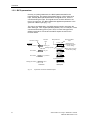
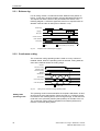
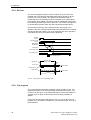
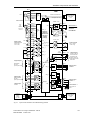
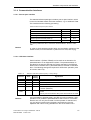
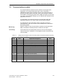
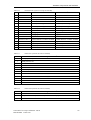
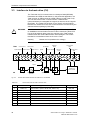
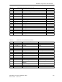
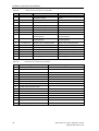
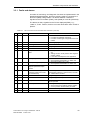
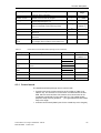
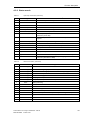
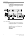
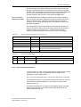
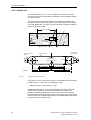
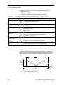
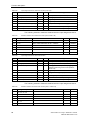
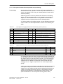
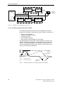
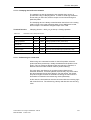
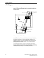
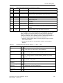
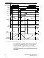
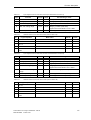
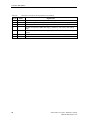
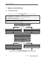
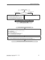
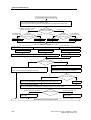
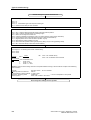
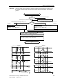
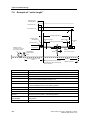
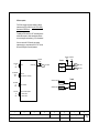
Function description
To monitor the lowering range, the range monitoring in Chart 350 (range
3) is used. This provides the option to shift the limits, as a function of the
velocity, whereby this is not used in the particular example.
Table 4-21
Defining the range, in which the knife may be lowered
Param
Value
Quantity
Significance (using the example)
L224
675
Range3_max
Upper limit value, where the knife may be in the lower position.
Example: max. time to raise the knife = 1.5 s
V_reference = 20 m/min
when raising the knife, distance moved = 500 mm
Range3_max = 1200 mm - 500 mm - 25 mm = 675 mm
Þ
Comment
In this particular example, the material is considered to have been cut
when the knife has been lowered (operation completed). It would be
more correct, so set the "material cut" status, when the knife actually
reaches the lower dead point. However, there is the danger that this
status would never be reached if, for a high material velocity and
mechanical delays, knife lowering would be interrupted before the lower
deadpoint is reached.
The conditions for the three control functions can be defined using this
range definition:
4.7.1.3 Parameterizable STATE logic
The logic functions in the table above should be considered as an
application example. For each actual plant or system, changes can be
expected to take into account plant or system secondary conditions. In
order to be able to create as many different versions as possible, logic
functions are not implemented in the form of individual gates, but as
parameterizable logic (refer to Chart 400).
A parameterizable STATE logic block has 8 BOOLean inputs (I1 ... I8),
which can be freely-connected to BOOLean connectors (e.g. to a digital
input which signals "knife at the top"). The type of logical combination is
defined using mask entries. Each mask selects which inputs or inverted
inputs are to be AND'ed.
Mask bit
Associated
input
15 14 13 12 11 10
9
8
7
6
5
4
3
2
1
0
I8
I2
I1
I8
I7
I6
I5
I4
I3
I2
I1
Example
Fig. 4-15
I7
I6
I5
I4
I3
MR1 = 16#8106 = 1000 0001 0000 0110b = I8 · I1 · I3 · I2
Assigning the selection mask bits to the inputs
4 set masks (MS1 ... MS4) and 3 reset masks (MR1 ... MR3) are
available. In addition, using the MR mask, the inputs can be selected
which cause the internal flipflops to be reset.
Sheet-Cutter/Cut to Length - SIMADYN D - Manual
6DD1903-0DB0 Edition 10.00
59