1
Standard Software Package
Axial Winder SPW420
for the
T400 Technology Board
Software Version 2.0
Axial winder SPW420 - SIMADYN D - Manual
6DD1903-0AB0
Edition 07.99
1
Warning information
Abbreviations
2
AG
Automation unit (PLC)
CB
Communications board such as CBP/CB1
CU
Base drive converter or converter
CUVC
New SIMOVERT MASTERDRIVES
CUMC
SIMOVERT MASTERDRIVES Motion Control
CUD1
SIMOREG DC MASTER
dxxx
Technology parameters, number xxx, cannot be changed
FB
Function block
Hxxx
Technology parameters, number xxx, can be changed
M
Torque
n
Speed
n_act
Speed actual value
n_set
Speed setpoint
PG
Programmer (e.g. PG685, PG730, PG750)
PTP (PtP)
Peer-to-peer communications
T400
T400 technology module
TA
Sampling time
b.d. n
Block diagram, Page n
v
Web velocity
USS
USS communications
Axial winder SPW420 - SIMADYN D - Manual
6DD1903-0AB0
Edition 07.99
Warning information
Contents
0 Warning information ...................................................................................... 6
1 Overview ......................................................................................................... 8
1.1 Validity ................................ ................................ ................................ .......................... 8
1.2 General overview ................................ ................................ ................................ .......... 8
1.2.1 T400 technology module ................................ ................................ ..................... 9
1.2.2 Interface module (CB) ................................ ................................ ........................ 10
1.3 Overview of the closed- loop winder control ................................ ................................ ..11
1.3.1 Hardware/software prerequisites ................................ ................................ .........11
1.3.2 Main features of the closed-loop winder control ................................ .................. 11
2 T400 technology module............................................................................. 13
2.1 Communication interfaces ................................ ................................ ............................ 13
2.1.1 Interface to the base drive converter (b.d. 15a) ................................ .................. 14
2.1.2 Interface to COMBOARD (b.d. 15) ................................ ................................ .....15
2.1.3 Interface to the peer-to-peer (b.d. 14) ................................ ................................ .16
2.1.4 USS slave interface (b.d. 14a) ................................ ................................ ............18
2.1.5 Interface to the monitor ................................ ................................ ...................... 18
2.2 Terminal assignment ................................ ................................ ................................ ....18
2.2.1 Digital inputs and outputs ................................ ................................ ................... 20
2.2.2 Analog inputs and outputs ................................ ................................ .................. 21
2.2.3 Pulse encoders ................................ ................................ ................................ ...22
3 Function description ................................................................................... 24
3.1 Reading-in setpoints ................................ ................................ ................................ .....25
3.1.1 General information (block diagrams 11-13) ................................ ....................... 25
3.1.2 Speed setpoint (block diagram 5) ................................ ................................ .......25
3.1.2.1 Main setpoint ................................ ................................ ........................ 25
3.1.2.2 Stretch compensation for a speed setpoint ................................ ............25
3.1.2.3 Speed setpoint for winder operation ................................ ...................... 26
3.1.2.4 Velocity setpoint for local operation ................................ ...................... 27
3.1.2.5 Limiting the velocity setpoint ................................ ................................ .29
3.1.2.6 Winder overcontrol ................................ ................................ ...............29
3.1.3 Setpoint for the closed-loop tension / position controller (block diagram 7/8) ......29
3.1.3.1 Winding hardness control (block diagram 7) ................................ .........30
3.1.3.2 Standstill tension (block diagram 7) ................................ ...................... 31
3.2 Sensing actual values ................................ ................................ ................................ ...32
3.2.1 Selectin g the speed actual value (block diagram 13) ................................ ..........32
3.2.2 Speed actual value calibration ................................ ................................ ............33
3.3 Control ................................ ................................ ................................ ......................... 34
3.3.1 Control signals (block diagrams 16/17/22b) ................................ ........................ 34
3.3.2 Winding direction ................................ ................................ ................................ 35
3.3.3 Gearbox stage changeover (block diagram 5) ................................ .................... 35
3.3.4 Two operating modes (block diagram 18) ................................ ........................... 36
3.3.5 Motorized potentiometer functions (block diagram 19) ................................ ........38
3.3.6 Splice control (block diagram 21) ................................ ................................ ........39
Axial winder SPW420- SIMADYN D -Manual
6DD1903-0AB0 Edition 07.99
3
Warning information
3.4 Closed-loop control ................................ ................................ ................................ ......41
3.4.1 Closed-loop control structure (block diagram 4) ................................ .................. 41
3.4.2 Closed-loop speed control (block diagram 6/6a) ................................ ................. 41
3.4.2.1 Influence of the speed controller (block diagram 6) ............................... 41
3.4.2.2 Kp adaptati on (block diagram 6a) ................................ ......................... 42
3.4.3 Closed-loop tension / dancer roll – position control (block diagram 7/8) .............. 43
3.4.3.1 Kp adaptation ................................ ................................ ....................... 44
3.4.3.2 D component of the t ension controller (block diagram 7) ....................... 45
3.4.4 Generating the supplementary torque setpoint (block diagram 6/ 9b) .................. 46
3.4.4.1 Compensation calculation (block diagram 9b) ................................ .......46
3.5 Calculation ................................ ................................ ................................ ................... 47
3.5.1 Diameter computer (block diagram 9a) ................................ ............................... 47
3.5.2 Length measurement and length stop (block diagram 13) ................................ ...50
3.6 Monitoring and sig naling ................................ ................................ ............................... 51
3.6.1 Web break detection (block diagram 7) ................................ .............................. 51
3.6.2 Freely-connectable limit value monitors (block diagram 10) ............................... 53
3.6.3 Analog outputs (block diagram 10) ................................ ................................ .....53
3.6.4 Overspeed (block diagram 20) ................................ ................................ ...........54
3.6.5 Excessive torque ................................ ................................ ................................ 54
3.6.6 Stall protection ................................ ................................ ................................ ...55
3.6.7 Receiving telegrams from CU, CB and PTP (block diagram 20) ......................... 55
3.7 Others ................................ ................................ ................................ .......................... 56
3.7.1 Free function blocks (block diagram 23a/23b) ................................ ..................... 56
3.7.2 Free display parameters (block diagram 25) ................................ ....................... 57
4 Configuring instructions and examples..................................................... 58
4.1 Some formulas for a winder drive ................................ ................................ ................. 58
4.2 Calculating the inertia compensation ................................ ................................ ............ 62
4.2.1 Determining parameter H228 for the fixed moment of inertia .............................. 62
4.2.2 Determining parameter H227 for the variable moment of inertia ......................... 64
4.3 Selecting the winding ratio (winding range) ................................ ................................ ...66
4.4 Power and torque ................................ ................................ ................................ .........66
4.5 Defining the sign ................................ ................................ ................................ ..........66
4.6 Selecting the closed-loop control concept ................................ ................................ .....68
4.6.1 Indirect closed-loop tension control (”Open-loop tension control”) ....................... 68
4.6.2 Direct closed-loop tension control with dancer roll ................................ .............. 69
4.6.3 Direct closed-loop tension control with a tension transducer ............................... 70
4.6.4 Closed-loop constant v control ................................ ................................ ............ 70
4.6.5 Selecting a suitable control concept ................................ ................................ ....70
4.7 Configuring example: Winder with indirect tension control ................................ ............ 71
4.8 Configuring example: Unwinder with indirect tension control ................................ ........74
4.9 Configuring example: Winder with dancer roll, speed correction ................................ ...77
4.10 Configuring example: Unwinder with dancer roll, speed correction ............................... 80
4.11 Configuring example: Winder with tension transducer ................................ .................. 83
4.12 Configuring example: Unwinder with tension transducer ................................ ............... 86
4.13 Configuring example: Winder with closed-loop constant v control ................................ .89
4.14 Configuring example: Cut tension with freely-assignable blocks ................................ ...91
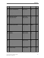
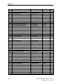
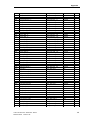
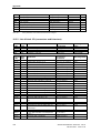
5 Parameters.................................................................................................... 92
5.1 Parameter hand ling ................................ ................................ ................................ ......92
5.2 Parameter lists ................................ ................................ ................................ ............. 93
6 Base drive parameters ............................................................................... 148
4
Axial winder SPW420 - SIMADYN D - Manual
6DD1903-0AB0
Edition 07.99
Warning information
7 Commissioning the winder ....................................................................... 150
7.1 Information on commissioning ................................ ................................ .................... 150
7.1.1 Resources used for adaptation and commissioning ................................ ..........151
7.1.2 Specification of the parameter numbers ................................ ........................... 151
7.1.3 BICO technology ................................ ................................ .............................. 152
7.1.4 Establishing the factory setting ................................ ................................ .........153
7.2 Commissioning the winder functions ................................ ................................ ...........154
7.2.1 Checking the speed actual value calibration ................................ ..................... 154
7.2.2 Compensati on, friction torque (block diagram 9b) ................................ ............. 154
7.2.2.1 Friction characteristic ................................ ................................ ..........155
7.2.3 Compensating the accelerating torque (block diagram 9b) ................................ 156
7.2.3.1 Constant moment of inertia, H228 ................................ ...................... 156
7.2.3.2 Variable moment of inertia, H227 ................................ ....................... 157
7.2.4 Setting the Kp adaptation for the speed control ................................ ................. 157
7.2.4.1 Setting on the T400 ................................ ................................ ............ 158
7.2.4.2 Setting for CUVC or CUMC ................................ ................................ 158
7.2.5 Setting the tension or dancer roll controller (block diagram 7/8) ........................ 158
7.2.6 Setting the tension controller, Kp a daptation ................................ ..................... 160
7.2.7 Setting the saturation setpoint H145 ................................ ................................ .161
7.2.8 Setting the braking characteristic H256-259 ................................ ...................... 161
7.3 Operation with the communications module (CBP/CB1) ................................ ............. 162
7.4 Operation with peer-to-peer ................................ ................................ ........................ 162
7.5 Operation with USS slave ................................ ................................ ........................... 163
7.6 Operation with free function blocks ................................ ................................ ............. 163
8 Diagnostic LEDs, alarms, faults ............................................................... 164
8.1 Diagnostic LEDs on the T400 ................................ ................................ ..................... 164
8.2 Alarms and faults of the axial winder ................................ ................................ ..........165
9 Literature .................................................................................................... 166
10 Appendix..................................................................................................... 167
10.1 Version changes ................................ ................................ ................................ .........167
10.2 Definition of the 5 cycle times ................................ ................................ ..................... 167
10.3 List of block I/O (connectors and parameters) ................................ ............................. 168
10.3.1 List of parameters and connections which can be changed ............................... 168
10.3.2 List of block I/O (connectors and binectors) ................................ ...................... 176
10.4 Block diagram ................................ ................................ ................................ ............ 182
10.5 CFC charts ................................ ................................ ................................ ................. 183
Axial winder SPW420- SIMADYN D -Manual
6DD1903-0AB0 Edition 07.99
5
Warning information
0 Warning information
WARNING
Electrical equipment has components which are at dangerous voltage levels.
If these instructions are not strictly adhered to, this can result in severe bodily
injury and material damage.
Only appropriately qualified personnel may work on/commission this
equipment.
This personnel must be completely knowledgable about all the warnings and
service measures according to this User Manual.
It is especially important that the warning information in the relevant
Operating Instructions (MASTERDRIVES or DC MASTER) is strictly
observed.
Definitions
h Qualified personnel for the purpose of this User Manual and product
labels
are personnel who are familiar with the installation, mounting, start-up
and operation of the equipment and the hazards involved. He or she
must have the following qualifications:
1. Trained and authorized to energize, de-energize, clear, ground and
tag circuits and equipment in accordance with established safety
procedures.
2. Trained in the proper care and use of protective equipment in
accordance with established safety procedures.
3. Trained in rendering first aid.
!
!
!
6
DANGER
For the purpose of this User Manual and product labels, „Danger“
indicates death, severe personal injury and/or substantial property
damage will result if proper precautions are not taken.
WARNING
For the purpose of this User Manual and product labels, „Warning“
indicates death, severe personal injury or property damage can result if
proper precautions are not taken
CAUTION
For the purpose of this User Manual and product labels, „Caution“
indicates that minor personal injury or material damage can result if
proper precautions are not taken.
Axial winder SPW420 - SIMADYN D - Manual
6DD1903-0AB0
Edition 07.99
Warning information
NOTE
For the purpose of this User Manual, „Note“ indicates information
about the product or the respective part of the User Manual which is
essential to highlight.
CAUTION
This board contains components which can be destroyed by electrostatic
discharge. Prior to touching any electronics board, your body must be
electrically discharged. This can be simply done by touching a conductive,
grounded object immediately beforehand (e.g. bare metal cabinet
components, socket protective conductor contact).
Axial winder SPW420- SIMADYN D -Manual
6DD1903-0AB0 Edition 07.99
7
Overview
1 Overview
1.1
Validity
This User Manual is valid for the standard ”Axial winder” SPW420
software package, Version 2.0. The configured software, based on
T300 MS320 (version 1.3) has been expanded, and has been
implemented on the T400 technology module (32 bit). Differences to the
previous versions will be shown in Chapter 10 ”Version changes”. This
SPW420 software can only run on the T400 technology module, both in
the drive converter as well as in the SRT400 subrack.
SPW420
Note
Base- and interface
modules
The control core (all of the functions) of the standard SPW420 software
package are essentially also available to other SIMADYN D modules
(PM4 - PM6 and FM 458 ).
This standard software package has been released for the SIMOVERT
MASTERDRIVES drive converters and the SIMOREG DC-MASTER
drive converters with the following base- and interface modules:
Base modules (CU):
• CUVC or CUMC, installed in the SIMOVERT MASTERDRIVES VC or
MC converters as well as the earlier CU2 or CU3 modules, installed in
SIMOVERT MASTERDRIVES VC or SC.
• SIMOREG DC-MASTER
Interface modules (CB):
Only the subsequently described slots and combinations have been
released:
• PROFIBUS interface module CBP on the ADB carrier module (lower
slot of the ADB), installed in slot 3 of the Electronics box, if a CUVC
or CUMC are used.
• PROFIBUS interface module CB1 at slot 3, if either CU2 or CU3 is
used.
• Peer-to-peer / USS interface module SCB1 or SCB2 at slot 3.
1.2
General overview
The digital SIMOVERT MASTERDRIVES and SIMOREG DC-MASTER
converters can be expanded by the T400 technology module and various
interface modules. Standard software packages are available for
applications which are frequently used, e.g. angular synchronism, sheetcutters or axial winder controls (closed-loop). If the technological
8
Axial winder SPW420 - SIMADYN D - Manual
6DD1903-0AB0
Edition 07.99
Overview
functions of the standard software packages have to be expanded to
fulfill specific customer requirements, then the software packages can be
purchased on CD-ROM, and then modified with the graphics CFC
configuring tool (from version 4.0).
The standard software packages can run with and without interface
module (e.g. CBP/CB1).
Note
Getting to know the software and commissioning:
1. Configuring examples , refer to Chapters 4.7 to 4.13.
2. Block diagrams (b.d.), refer to Appendix (Chapter 10. 4)
3. Controlling the configured winder software package via CBP/ CB1,
peer-to-peer and terminals, refer to the block diagram, Sheets 1 3a 19, 22 - 22b.
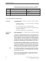
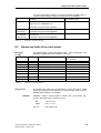
1.2.1 T400 technology module
The T400 technology module is a processor module, which can be freely
configured using CFC. It is compatible to SIMADYN D, and has been
especially designed for use with the SIMOVERT MASTERDRIVES,
SIMOREG DC-MASTER drive converters and SRT400 subracks. The
graphical CFC configuring tool is used to define the function of the
various modules. The generated software is downloaded into a program
memory of the T400. Table 1-1 shows an overview of the characteristics
of the T400 [1]. The communications with the base drive is realized via a
parallel interface, which is also implemented as dual port RAM (DPR).
In addition, the T400 can communicate via PROFIBUS DP, the USS bus
and peer-to-peer links. Refer to Chapter 2 for details.
Processor / clock
frequency
RISC R3081/ 32 MHz
RAM memory
4 Mbyte
Communications with CU
Parallel bus, dual port RAM, 16 words (each 16 bit)
Program memory
2 Mbyte EPROM and 32 kbyte EEPROM, 128 byte NOVRAM
Digital inputs
12
of which 4 bidirectional inputs or outputs
24 V
Digital outputs
6
of which 4 bidirectional inputs or outputs
24 V, 50 mA
Analog inputs
5
12-bit resolution
± 10 V (2 differential inputs)
Analog outputs
2
12-bit resolution
± 10 V, 10 mA
Serial interfaces
2
1* RS232 or RS485 (2-wire)
1* RS485 (2- or 4-wire)
Pulse encoder inputs
2
1* track A, B, zero, HTL (15V) or TTL/RS422 (5V)
1* track A, B, zero and coarse HTL pulse
Table 1-1
Overview of the T400 technology module
Axial winder SPW420- SIMADYN D -Manual
6DD1903-0AB0 Edition 07.99
9
Overview
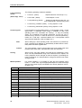
Prerequisite
The following components are required to operate the SPW420 axial
winder:
Product description
Order No.
Software package, SPW420 axial winder with T400
6DD1842-0AA0
Operating Instructions T400, German
6DD1902-0EB0
Manual, axial winder SPW420
German
6DD1903-0AA0
English
6DD1903-0AB0
French
6DD1903-0AC0
Table 1-2
Adaptation
possibility
SPW420 components required
The source code of the standard SPW420 axial winder software package
is available on CD-ROM. Using the graphic configuring platform of
SIMADYN D, i.e. CFC, when required, the functionality of the closedloop winder control can be adapted to specific customer requirements.
The individual components in Table 1-3 are also available:
Product description
Order No.
Axial winder software ( CD-ROM) including User
Manual
6DD1843-0AA0
T400 technology module
6DD1606-0AD0
D7-ES V5.0
6DD1801-4DA2
(complete software package: STEP7, CFC, D7SYS)
Or Service-IBS V5.0 ( German/English )
Table 1-3
6DD1803-1BA1
Components to adapt the software package using CFC
1.2.2 Interface module (CB)
For applications which require the SIMOVERT MASTERDRIVES or
SIMOREG DC-MASTER drive converters to be coupled with a higherlevel automation system, interface modules are used, depending on the
protocol used. Thus, it is possible for automation systems to read and
change setpoints, actual values, technology parameters as well as base
drive converter parameters.
PROFIBUS DP is the preferred communications type. In this case, the
interface modules CBP with ADP or CB1 are required; also refer to
Chapter 1.1.
10
Axial winder SPW420 - SIMADYN D - Manual
6DD1903-0AB0
Edition 07.99
Overview
1.3
Overview of the closed-loop winder control
Applications
The standard ”Axial winder” software package allows, in conjunction with
the appropriate devices, winders and unwinders to be implemented for
the widest range of applications. This include for example, foil machines,
all types of printing machines, coating systems, paper finishing
machines, coilers for wire-drawing machines, textile machines and
coilers for sheet steel.
1.3.1 Hardware/software prerequisites
Hardware
The drive converter must be designed for 4 Q operation, as braking must
be possible.
Software
The minimum software releases are required as follows:
Base drive converter modules:
• CU2: Software release ≥ 1.2
• CU3: Software release ≥ 1.1
• CUVC: Software release ≥ 3.0
• CUMC: Software release ≥ 1.1
• CUD1: Software release ≥ 1.3.
Interface modules:
• CBP: Software release ≥ 1.0
• CB1: Software release ≥ 1.3
Configuring tool (if the software is not only to be just
parameterized):
• STEP7, CFC, D7-SYS: Software release ≥ 4.0
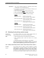
1.3.2 Main features of the closed-loop winder control
Function
−
various winding techniques, e.g. direct closed-loop tension control,
indirect closed-loop tension control or closed-loop constant v control
are possible ;
−
override speed controller (the tension controller acts directly on the
motor torque) or the speed correction technique (the tension controller
acts on the speed setpoint), switchable ;
−
tension controller- and speed controller gain adaptation as a function
of the diameter ;
−
winding hardness control using a polygon characteristic with 5 points,
diameter-dependent, can be parameterized ;
Axial winder SPW420- SIMADYN D -Manual
6DD1903-0AB0 Edition 07.99
11
Overview
Communications
Monitoring
Operating mode
Measured value
sensing
12
−
speed-dependent friction compensation using a polygon characteristic
with 6 points, can be parameterized ;
−
acceleration pre-control as a function of the diameter as well as the
web width, gearbox stage and material thickness. The thickness can
be automatically learned ;
−
tension pre-control as a function of the diameter and tension setpoint ;
−
two techniques to calculate the diameter, i.e. with/without v set signals;
−
diameter calculation with a control function for ’Set diameter’ and
’Hold diameter’;
−
web length calculation ;
−
it is possible to changeover between several gearbox stages ;
−
free function blocks for additional user-specific requirements ;
−
freely-assignable display parameters to visualize the actual value of
the connector/binector .
−
data transfer to the base drive converter and via PROFIBUS DP,
peer-to-peer, USS and digital or analog I/O possible ;
−
versatile as it is possible, within the standard axial winder software, to
freely-interconnect analog and digital inputs, analog and digital
outputs as well as parts of the dual port RAM to the interface module
and to the base drive using BICO technology (start-up program).
−
optional web break detection and the appropriate measures ;
−
automatic standstill identification and switching to standstill tension ;
−
monitoring of all communication interfaces ;
−
winder-related open-loop control with alarm- and fault evaluation
−
automatic protection against web sag .
−
suitable for winders and unwinders with and without flying reel change
for changeover mechanical system.
−
inching-, positioning- and crawl operation.
−
two motorized potentiometers which can be freely used.
−
shutdown without overshoot, with braking characteristic for fast stop.
−
tension transducer or dancer roll can be connected ;
−
two pulse encoders can be connected to measure the motor speed
and web velocity ;
−
surface tachometer can be connected to sense the diameter actual
value .
;
Axial winder SPW420 - SIMADYN D - Manual
6DD1903-0AB0
Edition 07.99
T400 technology module
2 T400 technology module
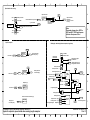
2.1
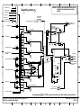
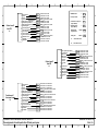
Communication interfaces
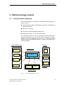
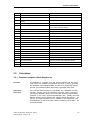
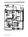
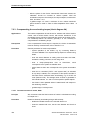
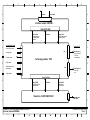
All of the T400 interfaces, included in the standard software package, are
shown in Fig. 2-1:
n Communications interface: PROFIBUS, peer-to-peer, USS-BUS and
PC/start-up interface
n Base drive or converter
n I/O interface: Analog and digital inputs/outputs
n Actual value sensing: Two incremental encoder s
The closed-loop control core of the axial winder and the actual value
sensing is executed on the T400. Its functions are explained in detail in
Chapter 3. All of the interfaces, shown in Fig. 2-1, which are used to
transfer process- and parameter data with the T400, are described in the
following Chapters.
Communications interface
Basic drive
Control core
BUS connection
CUx
(CBP, CB1)
T400
USS
Alt
ern
ati
v
Analog
I/O
PC
interface
Digital
I/O
Peer to peer
Incremental
encoder 1
Incremental
encoder 2
I/O interface
Actual value sensing
Fig. 2-1
Communications interface for T400
Axial winder SPW420- SIMADYN D -Manual
6DD1903-0AB0 Edition 07.99
13
T400 technology module
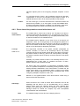
2.1.1 Interface to the base drive converter ( b.d. 15a)
Communications
with CU
Fast process data and parameter transfer as well as faults/alarms
between the T400 technology module and the base drive is realized
using the backplane bus via a parallel dual port RAM interface.
The process data, i.e. the setpoints and actual values are cyclically
written and read by the technology module and base drive. Parameters
are read and changed, task-controlled.
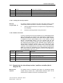
Base drive setting
NOTE
The base drive must be commissioned. In order to operate the standard
SPW420 software package, the following parameters must be set on the
base drive for the setpoint/actual value channels and control / status
words, refer to Table 2-1, Table 2-2 and Chapter 6.
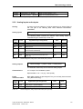
In Table 2-1 and Table 2-2
Pxxx: Base drive parameters
Hxxx: T400 parameter
Setpoint channels
T400 --> CU
The technology module transfers 10 words to the base drive. 8 of these
words are defined as in Table 2-1. The other 2 words can be freely
connected. The control word transferred is generated by the automation
(higher-level open-loop control, data transfer via the interface module) or
from the T400 terminals and fixed values.
CUVC CUMC
CUD1
param. param. param.
P648
P649
P554
P554
P654
P555
P555
P655
P558
P558
P658
P561
P561
P661
P565
P565
P665
P575
P575
P675
P443
P443
P625
P585
P585
P685
P506
P262
P501
P493
P265
P605
P499
P266
P606
P232
P232
P553
Table 2-1
Act. value
channels
CU --> T400
14
Value Explanation
Word . bit
Sampl. Par.
time
T400
9
9
3100
3101
3102
3103
3107
3115
3002
3409
3005
3006
3007
3008
3009
3010
Word 1.0
Word 1.1
Word 1.2
Word 1.3
Word 1.7
Word 1.15
Word 2
Word 4.9
Word 5
Word 6
Word 7
Word 8
Word 9
Word 10
16 ms
16 ms
16 ms
16 ms
16 ms
16 ms
2 ms
16 ms
2 ms
2 ms
2 ms
2 ms
2 ms
2 ms
Source for control word 1
Source for control word 2
On command ( main contactor )
Off2
Off3
Pulse enable
Acknowledge fault
External fault
Speed setpoint
Speed controller enable
Supplement. torque setpoint
Positive torque limit
Negative torque limit
Variable moment of inertia
free
free
H500
H519
H501
H502
H503
H504
H505
H506
Control word- and setpoint channel from the T400 to the base d rive
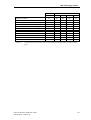
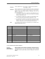
The technology module receives 8 words from the base drive; the
sequence and the contents are defined with appropriate parameters, e.g.
P734 for CUVC. Status word 1 which is transferred is logically combined
with the status messages of the T400, and transferred to the automation.
Various status bits are evaluated in the configured software.
Axial winder SPW420 - SIMADYN D - Manual
6DD1903-0AB0
Edition 07.99
T400 technology module
Additional status words and actual values can be sent from the base
drive to the T400 via the backplane bus for monitoring, setpoint from the
CU or for output.
CUVC/
Param.
P734.01
P734.02
P734.03
P734.04
P734.05
P734.06
P734.07
P734.08
Table 2-2
CUMC
Value
32
148/91
0
CU
Param.
U734.01
U734.02
U734.03
U734.04
165
U734.05
24/241 U734.06
0
U734.07
0
U734.08
D1
Explanation
Word
Status word 1 (block diag. 22)
Receive word 2 (free)
Receive word 3 (free)
Status word 2 (not used)
Torque setpoint
Torque actual value
Receive word 7 (free)
Receive word 8 (free)
Word 1
Word 2
Word 3
Word 4
Word 5
Word 6
Word 7
Word 8
Value
32
167
0
141
142
0
0
Sampl.
time
16 ms
2 ms
2 ms
Par.
T400
2 ms
2 ms
2 ms
2 ms
d552
d553
d554
d555
d550
d551
Status word- and actual value channel from the base drive to T400
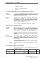
2.1.2 Interface to COMBOARD (b.d. 15)
Communications
via PROFIBUS DP
Permanently set and freely selectable setpoints/actual values can be
transferred via the COMBOARD communications module (in this case,
only CB1 or CBP/ADB). The T400 with the COMBOARD only has a
PROFIBUS slave function.
The COMBOARD is parameterized on the base drive, such as e. g. PPO
type, baud rate, telegram length etc., refer to Lit. [2-4]). The standard
software package defines which data should be transferred. It occupies
10 process data. Some of them can be freely selected.
NOTE
Cycle time
Various protocol versions are available for the PROFIBUS. PPO type 5
is used in this software package. This type includes 10 process data
(each 16-bit words) and parameters.
Data is transferred between the communication modules and the
technology module via dual port RAM. The process data (setpoints and
actual values) are read or written from the T400 in the fastest cycle time
(2 ms).
T400 in the SRT400
Parameterization from the T400 is only realized when the T400 is
operated in the standalone mode in the SRT400 with COMBOARD at
slot 2. Parameters H602-H604 are provided for this special case.
Enable H288
The configured software can be operated with and without a
communications module. If the communications module is not used,
PROFIBUS communications for the configured software can be
deactivated using parameter H288. This then relieves the CPU, and
disables the monitoring function. In addition, parameters H011 and H012
(alarm / fault suppression mask) must be appropriately set (refer to
Chapter 5).
Receive data
SPW420 expects a maximum of 10 words of process data from a higherlevel automation system (8 setpoints and 2 control words). The setpoints
which are transferred, can be freely connected within the software using
BICO technology so that they do not have a fixed assignment (refer to
COMBD --> T400
Axial winder SPW420- SIMADYN D -Manual
6DD1903-0AB0 Edition 07.99
15
T400 technology module
block diagrams 2 , 15 and 22a). The telegram structure for PROFIBUS
DP is shown in Table 2-3 (with PPO type 5).
Telegram word
Receive data
Parameter (T400)
1
Control word 1 (control word 1 T400)
Refer to block diagram 15/22a
2
Setpoint W2 (free)
d450 refer to block diagram 15
3
Setpoint W3 (free)
d451 refer to block diagram 15
4
Control word 2 (control word 2 T400)
Refer to block diagram 22a
5
Setpoint W5 (free)
d452 refer to block diagram 15
6
Setpoint W6 (free)
d453 refer to block diagram 15
7
Setpoint W7 (free)
d454 refer to block diagram 15
8
Setpoint W8 (free)
d455 refer to block diagram 15
9
Setpoint W9 (free)
d456 refer to block diagram 15
10
Setpoint W10 (free)
d457 refer to block diagram 15
Table 2-3
Receive channels from PROFIBUS (2 ms sampling time)
Send data
T400 --> COMBD
The send data (actual value/status word) selection can also be
parameterized.
Telegram word
Send data (pre-assignment)
Parameter (T400)
1
Status word 1 (status word 1 T400)
H444(4335) r.t.b.d. 15/22
2
Actual value W2 (actual diameter)
H440(310) r.t.b.d. 15
3
Actual value W3 (free)
H441(0)
4
Status word (status word 2 T400)
H445(4336) r.t.b.d. 15/22
5
Actual value W5 (free)
H442(0)
r.t.b.d. 15
6
Actual value W6 (free)
H443(0)
r.t.b.d. 15
7
Actual value W7 (free)
H446(0)
r.t.b.d. 15
8
Actual value W8 (free)
H447(0)
r.t.b.d. 15
9
Actual value W9 (free)
H448(0)
r.t.b.d. 15
10
Actual value W10 (free)
H449(0)
r.t.b.d. 15
Table 2-4
r.t.b.d. 15
Send channels (sampling time 2 ms)
Monitoring the
telegram receive
The telegram data transfer can be monitored during communications.
The time limits after power-on and during operation can be set
separately (H495-496). The fault- and alarm messages are transferred to
the CU, where they are displayed, if a data suppression mask
(H011,H012) has not been activated (refer to Chapter 8.2).
2.1.3 Interface to the peer-to-peer (b.d. 14)
Communications
via peer-to-peer
16
Axial winder SPW420 - SIMADYN D - Manual
6DD1903-0AB0
Edition 07.99
T400 technology module
The serial interface X02 is assigned to the peer-to-peer protocol through
configuring. This protocol allows data to be extremely quickly transferred,
without any delay, to
- additional T400
- other drive converters with SCB 2
- SIMOREG 6RA24 and 6RA70
refer to Table 2-5 and Table 2-6.
Pre-assignment
This interface has the following pre-assignment:
- baud rate (H245):
19200 baud
- monitoring time limit (H246-H247):
10000 - 9920ms
- telegram length:
5 words (1 control word and 4 setpoints)
NOTE
The telegram may include a maximum of 5 words (each 16 bit). The
maximum baud rate is 38400 baud.
Caution
The terminating resistors of the interface used must be switched-in to
avoid data transfer disturbances (switch S1/ 3 to S1/6; refer to [1,5]).
The peer-to-peer communications can be inhibited using parameter
H289. Thus, all of the peer-to-peer relevant function blocks are
deactivated.
Enable
Telegram word
Receive data
Parameter (T400)
1
Control word 1
refer to block diagram 22a
2
Setpoint W2
d018 refer to b.d. 14
3
Setpoint W3
d019 refer to b.d. 14
4
Setpoint W4
d066 refer to b.d. 14
5
Setpoint W5
d067 refer to b.d. 14
Table 2-5
Receive data from peer-to-peer (2 ms sampling time)
Telegram word
Send data
Parameter (T400)
1
Status word 1(status word 1 from T400)
H015 (4335) r.t.b.d. 22b
2
Actual value W2 (actual diameter )
H016(310) r.t.b.d. 14
3
Actual value W3 (velocity setpoint)
H017(340) r.t.b.d. 14
4
Actual value W4
H064(0) r.t.b.d. 14
5
Actual value W5
H065(0) r.t.b.d. 14
Table 2-6
Send data from peer-to-peer (2 ms sampling time)
Monitoring
telegram receive
The telegram data transfer can be monitored during communications.
The time limits after power-on and during operation can be set
separately (H246-H247). The fault- and alarm messages are transferred
to the CU and displayed on the PMU, if a data suppression mask (H011H012) has not been activated (refer to Chapter 8.2).
Axial winder SPW420- SIMADYN D -Manual
6DD1903-0AB0 Edition 07.99
17
T400 technology module
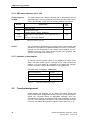
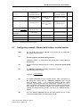
2.1.4 USS slave interface (b.d. 14a)
Communications
via USS
The serial interface X01 (RS232 / RS485) can be alternatively used for
parameterization. This is provided for the special case where the T400 is
used in the SRT400. In this case, the following settings are required:
Involves
Significance
⇒ 1
H600
Enable USS slave
H601
USS data transfer cable
0: RS485 (OP1S) 1: RS232 (SIMOVIS)
S1/8
on T400
Table 2-7
Caution
Act.
value
1
0
Changeover from online operation (CFC, simple start-up) to
USS.
ON: USS, OFF: Online operation
OFF
Settings for USS slave operation
It is not possible to simultaneously use USS and be in online mode! USS
operation is not possible if the parameterization is incorrect. This means,
the error can only be removed, if you re-select online operation, and, for
example, rectify the error using the Service-IBS tool. Operation with
OP1S is only possible from version 2.2.
2.1.5 Interface to the monitor
An operator control program, based on the SIMADYN D monitor (CFC
online and Service-IBS ) can be connected at the serial interface X01
(RS232). This then allows all connectors to be viewed and changed.
Further, connection changes are possible (not using SIMOVIS).
The baud rate is, as standard 19200 baud.
Terminal designation
Function
67
RxD
68
TxD
69
Ground
Table 2-8
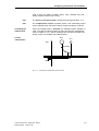
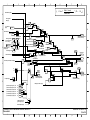
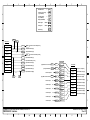
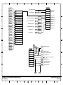
2.2
Terminals of interface X01 on T400
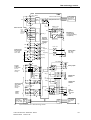
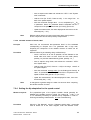
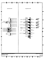
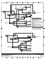
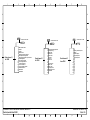
Terminal assignment
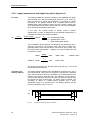
Control signals and setpoints can be read-in and status signals and
actual values output via digital and analog channels. For T400, the plant
signals are connected directly at appropriate terminals, which are
accessible from the front. An overview of the T400 connections is shown
in Fig. 2-2. The subsequent description of the terminal assignment refers
to this Fig. For additional information regarding T400, refer to Lit. [1, 5].
18
Axial winder SPW420 - SIMADYN D - Manual
6DD1903-0AB0
Edition 07.99
T400 technology module
T400
80 +15V / 100mA
81 Track A
82 Track B
HTL
Pulse
83 Zero pulseencod.1
Tracks A and B from CUx
MASTER DRIVES
or DC-MASTER
Zero pulse from CUx
Basic drive
converter CUx
84 Coarse pulse
85
Pulse encoder
Increm_1
M
Fct.block
62 Track A +
63 Track B +
HTL/
TTL
(RS422)
T/Rx+ 70
64 0 pulse +
65 Coarse p. Pulse
encod.
66
2
M
Selected with
switch S2
RS485, 2-wire
X01
T/Rx- 71
69
Increm_2
TxD
TTL
Hardwareaddresses
of the basic
configured
software
87 Track B 88 0 pulse -.
5 analog inputs
differential inputs
11 bits + sign
±10V / 10kΩ
±10V
90
91
±10V
92
93
94
+
-
A
+
-
A
+
-
±10V
95
±10V
68
RxD 67
86 Track A -
D
D
A
RS232
Ana_In_1
Ana_In_2
Ana_Out_1
11 bit + VZ
97
D
A
Ana_In_3
D
+
-
A
+
-
A
D
Serial interface 1
- Program download
- CFC test mode (start-up)
- USS (SIMOVIS)
Ana_Out_2
Ana_In_4
98
D
2 analog outputs
±10V / 10mA
11 bits + sign
A
99
96
±10V
99
M
50
M
45
P24 external
+24V 46
47
48
49
4 binary
outputs
bi-directional
24V DC
(8mA input
current)
Ana_In_5
D
P24 external 45
+24V
50
51
2 binary o utputs
52
BinInOut
(bidirectional)
76
77
78
79
SSI_1
Absolute value
encoder 1
Fct.block
53
54
55
4 binary inputs
alarm-capable
24V DC
(8mA input
current)
61
+24V
4 binaryinputs
24V DC
Communications module
e.g. CB1, ADB
SSI_2
Absolute value
encoder 2
M
72
BinInput
56
57
58
59
60
73
X02
Fct.block
Dualport
RAM
or
74
75
Dual
port
RAM
Serial
interface 2:
for
- peer-to-peer
- USS
MASTER DRIVES
or DC-MASTER
basic drive
CUx
Fig
. 2-2
Layout of the terminals of T400 technology module
Axial winder SPW420- SIMADYN D -Manual
6DD1903-0AB0 Edition 07.99
19
T400 technology module
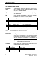
2.2.1 Digital inputs and outputs
Power supply
voltage
The digital inputs and outputs of the T400 technology module require or
supply 24 volt signals. In this case, the 24 V supply voltage for the digital
outputs must be externally supplied.
Digital control
inputs
The SPW420 closed-loop control core uses all of the 8 digital inputs on
the T400 (Table 2-9). When required, the default values (pre-assigned
values) can be changed .
Bit inversion
H295
When required, it is possible to invert each bit of the digital inputs by
using the appropriate parameterization. To realize this, the appropriate
bit of parameter H295 must be set to 1; refer to Chapter 5.
Term.
Connector
53
B2003
System start (H021)
1 = operation enable for system operation
54
B2004
Tension control on (H022)
1 = on, switch-in the closed-loop tension control
55
B2005
Inhib. tension contr . (H023)
1 = inhibit, tension controller output = 0
56
B2006
Set diameter (H024)
1 = set, transfer setting diameter
57
B2007
Enter suppl.. Vset (H025)
1 = yes, addition, supplementary velocity setpoint
58
B2008
Local positioning (H026)
1 = yes, local operation with positioning ref. value
59
B2009
Local operator control (H027) 1 = local, local/system operation changeover
60
B2010
Local stop (H028)
Table 2-9
Assignment
Explanation
1 = stop for local operation
Terminal assignment, digital inputs, T400 module (16ms cycle time)
Digital outputs
The digital outputs are used for status signals as well as during start-up
and during winding, refer to Table 2-10.
Characteristics
When the drive is first powered-up, all of the outputs are first inhibited
(high-ohmic state). In the initialization phase, they are controlled with the
values which are present at that time. When the drive is shutdown, or
under a fault condition, all of the outputs are connected to ground.
NOTE
Freely interconnectable
Terminal
Logical ”0”: Output is open or connected to ground
Logical ”1”: Output is closed, i.e. the power supply voltage
connected at the terminal (24V) is present.
The following table shows the pre-assigned digital outputs of the T400
technology module. The digital outputs can be freely inter-connected
using BICO-technology or Service-IBS program.
Assignment (binector)
Explanation
46 (H521)
Web break (B2501)
Web break detected
47 (H522)
Standstill (V act = 0) (B2502)
Speed actual value < H157
48 (H523)
Tension controller on (B2503)
Tension/pos . controller on, speed contr . enabled
49(H524)
Base drive on (B2504)
Operating signal from the base drive
20
Axial winder SPW420 - SIMADYN D - Manual
6DD1903-0AB0
Edition 07.99
T400 technology module
52(H525)
Speed setpoint =0 (B2505)
Speed controller setpoint < 0.1%
51(H526)
Limit value monitor 1 (B2114)
Output can be parameterized, H114
Table 2-10 Terminal assignment, digital outputs, T400 module (16ms cycle time)
2.2.2 Analog inputs and outputs
Scaling
An output- and input voltage of 10 V corresponds to an internal value of
1.0. The gain in the following table offers additional normalization
possibilities.
Analog inputs
Analog value = terminal voltage ⋅ scaling factor - offset
The following tables indicate the relevant T400 analog inputs for
commissioning the closed-loop control core.
Para. in
T400
Term.
Significance (pre-assignment)
Gain
Offset
d320
90/91
Analog input 1
H054
H055
d321
92/93
Analog input 2
H056
H057
d322
94/99
Analog input 3, smoothed (tension actual value
from the tension transducer)
H058
H059
d323
95/99
Analog input 4, smoothed
H060
H061
d324
96/99
Analog input 5 (pressure actual value from
dancer roll)
H062
H063
Table 2-11
Terminal assignment, analog inputs, T400 module (2ms cycle time)
Analog outputs
Terminal voltage = ( value + offset ) ⋅ scaling factor
The SPW420 closed-loop control used two analog outputs.
Characteristics
0 V is output in the initialization phase.
Representation: 10V = 1.0 (e.g. 100% speed)
Freely
interconnectable
Para. in
T400
Term.
Both analog outputs are pre-assigned. They can be freely interconnected
using BICO technology .
Significance (pre-assignment)
Gain
offset
H103
97/99
Analog output 1 (torque setpoint)
H102
H101
H098
98/99
Analog output 2 (diameter actual value)
H100
H099
Table 2-12
Terminal assignment, analog outputs T400 module (2ms cycle time)
Axial winder SPW420- SIMADYN D -Manual
6DD1903-0AB0 Edition 07.99
21
T400 technology module
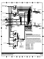
2.2.3 Pulse encoders
Pulse encoder type
Pulse encoders with two tracks shifted through 90 degrees must be
connected.
Encoder power
supply
15 V (max. 100 mA) must be available from the T400 module as
encoder power supply.
Screening
Encoders with a 15 - 24 V supply voltage, especially: 1XP8001-1
SIEMENS pulse encoders (for 1LA5 motors, frame sizes 100K to 200L).
The pulse encoder cable must be screened. The cable screen should be
connected to ground through the lowest impedance, if possible using
cable clamps. This must be especially observed, if these signal cables
are routed close to proximity switches or switches with moving contacts.
15 V power supply
units
If the 100 mA of the internal 15 V power supply is not sufficient, then the
following 15V power supply units are recommended:
• Type CM62-PS-220 AC/ 15 DC/ 1
220 V AC to 15V DC, 1 A load capability
Manufacturer, Phoenix
• Type FMP 15S 500 ”fast mounting”
110/220 V AC to 15V DC, 0.5 A load capability
Manufacturer, Block
Encoder pulse
numbers
When selecting the encoder pulse number, the maximum pulse
frequency is 1.5 MHz.
Pulse encoders 1/2 from the axle/web tachometer, are connected directly
to the CU/T400. The T400 can use the shaft tachometer signals from the
base drive (CU) via the backplane bus.
The mode can be parameterized using parameters H217 and H218. The
following should be set:
• Encoder type
• Filter parameterization and filter time constant of the digital filter for
the signals from the two pulse tracks / zero pulse track
• Source of the encoder tracks
The recommended values for H217 and H218 are specified in the
parameter table in Chapter 5. For more detailed information refer to
Lit.[6], block NAVS, connector MOD.
22
Axial winder SPW420 - SIMADYN D - Manual
6DD1903-0AB0
Edition 07.99
T400 technology module
Encoder 1
Track A+ or track A
Track A-
Encoder 2
HTL
RS422
HTL
TTL
HTL ±3V
81
62
62
62
62
-
86
-
-
-
82
63
63
63
63
-
87
-
-
-
P15 – output to the 15 V encoder supply
80
80
80
80
80
Ground
85
66
66
66
66
Switch S1.1
ON
OFF
ON
OFF
Switch S2.2
ON
OFF
ON
OFF
Switch S2.3
ON
OFF
OFF
ON
Switch S2.4
ON
OFF
ON
OFF
Switch S2.5
ON
OFF
OFF
ON
Track B+ or track B
Track B-
Table 2-13
Incremental encoder inputs of th e T400: Terminal assignment and switch settings for various encoder
types
Axial winder SPW420- SIMADYN D -Manual
6DD1903-0AB0 Edition 07.99
23
Function description
3 Function description
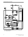
Overview
The standard axial winder software package was developed with the goal
of being able to cover many of the known winder applications using one
single software package. Using the freely configurable T400 technology
module, and the CFC configuring language, universal function units were
created, which can be easily adapted to the particular system
configuration by parameterization. Flexible interconnection of the control
signals and setpoints allows control from higher-level system as well as
operator control via the technology module terminals. ”Mixed operation”
is also possible.
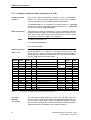
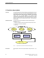
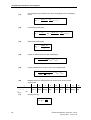
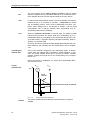
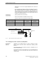
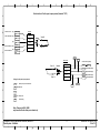
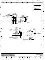
Software structure
The rough structure of the standard SP W420 software package is
illustrated in Fig. 3-1:
1. Reading-in setpoints, sensing actual values and open-loop controls
2. Closed-loop control and computation
3. Monitoring
Read-in
setpoints
Sense
actual values
Closed-loop
control
Open-loop
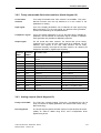
control
Computation
Monitoring
Fig. 3-1
Description
24
Rough structure of the standard axial winder software package
The description of all of the functions follows the rough structure in Fig.
3-1.
Axial winder SPW420 - SIMADYN D - Manual
6DD1903-0AB0
Edition 07.99
Function description
3.1
Reading-in setpoints
3.1.1 General information (block diagrams 11-13)
The selection and interconnection of the setpoints to be processed is
realized using BICO technology . Each setpoint can be freely selected
from a max. of 6 sources. The following input signals are available:
Source for
selection
•
•
•
•
•
•
5 analog inputs of the T400 module
10 setpoints from PROFIBUS DP
5 setpoints from the peer to peer link
3 setpoints from the CU
2 motorized potentiometers
1 fixed setpoint as parameter
In the factory setting, the setpoints are connected with a fixed setpoint,
which is generally pre-assigned (default value) 0.0.
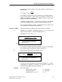
3.1.2 Speed setpoint (block diagram 5)
3.1.2.1 Main setpoint
The main setpoint of the web speed for the winder drive is selected using
parameter H069 (block diagram 11). The incoming web speed setpoint is
normalized using parameter H139, so that the required speed ratio is
obtained for the winder. The effective web speed setpoint is available as
visualization parameter d301.
Parameter Parameter name
Explanation
H069
Source, speed setpoint
Freely connectable from the source, refer to Chapter 5
H127
Fixed value, ratio gearbox stage 2
Ratio between gearbox stages 1 and 2 in %, refer to
Chapter 5
H138
Source ratio, gearbox stage 2
Refer to Chapter 5
H139
Normalization, web speed
Refer to Chapter 5
d301
Effective web speed setpoint
After normalization and taking into account a gearbox
stage changeover
Table 3-1
Parameters to set the speed setpoint
3.1.2.2 Stretch compensation for a speed setpoint
The main web speed setpoint can be influenced to provide ”stretch
compensation”, if the material thickness is to be reduced before winding,
e.g. by stretching or expansion. To realize this, a compensation setpoint
should be selected using parameter H071. A fixed value is selected via
H070, presetting 0.0 with the standard H071 connection. The web speed
compensation can be normalized using parameter H137.
Note
The web speed compensation should only be set, if a deviation has been
identified between the web speed setpoint and actual value. This
Axial winder SPW420- SIMADYN D -Manual
6DD1903-0AB0 Edition 07.99
25
Function description
difference influences, among other things, the accuracy of the diameter
computation and the speed of the winding shaft at the flying roll change.
Parameter Parameter name
H070
Fixed value, web speed compensation
H071
Source, web speed compensation
H137
Normalized speed compensation
d340
Compensated web speed
Table 3-2
Explanation
Freely-connectable from the source, refer
to Chapter 5
Parameters to enter the web speed setpoint compensation
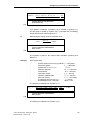
3.1.2.3 Speed setpoint for winder operation
Prerequisite
The following operator controls are required for winder operation
(‘system operation’):
• Command ”Off1/On” = 1 active, the base drive is powered-on
(main contactor closed)
• The ”Local operator control” control signal must be 0.
• The software package and base drive wait for an operation enable
signal from ”System start”.
• The winder accelerates up to the specified setpoint.
Central rampfunction
generator
For this ‘system operation‘, a central ramp-function generator is effective
for the speed setpoint.
The ramp-up / ramp-down times and the ramp-up / ramp-down roundingoff functions are set using parameters H133, H134, H135 and H136. The
upper and lower limits can be specified using parameters H131 and
H132. The value from H130 can be entered as new setpoint using the
“Accept setpoint B” command via H037. The ”Accept setpoint A”
command H036 switches a new selectable setpoint (block diagram 13)
with H096. The ramp-function generator is held with the ”Ramp-function
generator hold” command H049 or ”Set speed setpoint to stop” H034.
The speed setpoint is transferred directly to the closed-loop control
without being influenced by the ramp-function generator, using H154 = 1.
In this case, it is possible to use smoothing, which can be set using
H155. This operating mode is practical, if the setpoint provided is already
available at the ramp-function generator output (e.g. winder as slave
drive, setpoint from the central machine control or from another drive).
Note
The ramp-function generator can also be used as smoothing element,
e.g. for entering a setpoint from a web velocity tachometer. The ramp-up
and ramp-down times should be set somewhat lower than the web
velocity changes which occur.
Using the ”Input supplementary setpoint” command H025, a setpoint
source, which can be selected with H073, is added directly in front of the
speed controller (block diagram 5).
26
Axial winder SPW420 - SIMADYN D - Manual
6DD1903-0AB0
Edition 07.99
Function description
Parameter Parameter name
Explanation
H021
Source, system start
Command, system start, refer to Chapter 5
H025
Source, input supplementary
setpoint
Command, input supplementary setpoint
H034
Source, velocity setpoint, set to
stop
Command, velocity setpoint, set to stop
H036
Source, accept setpoint A
Command, accept setpoint A
H037
Source, accept setpoint B
Command, accept setpoint B
H045
Source, Off1/On
Command, Off1/On (main contactor)
H049
Source, ramp-function generator
stop
Command, ramp-function generator stop
H073
Source, suppl. velocity setpoint
Refer to Chapter 5
H096
Source, setpoint A
Selects the source for setpoint A, refer to Chapter 5
H130
Setpoint B
Fixed value as velocity setpoint, is entered with the
‘Accept setpoint B’ control signal (H037) in front of the
ramp-function generator.
H131
Upper limit of the RFG
Limiting, maximum value
H132
Lower limit of the RFG
Limiting, minimum value
H133
Ramp-up time
H134
Ramp-down time
H135
Rounding-off at ramp-up
H136
Rounding-off at ramp-down
H138
Source ratio, gearbox stage 2
Ratio of the gearbox stages, between stage 1 and stage
2 as a %
H139
Normalization, web velocity
Refer to Table 3-1
H154
Slave drive
Disables the central ramp-function generator for the
velocity setpoint, if the winder operates as a slave drive
H155
Smoothing, web velocity setpoint
Setpoint smoothing, if the ramp-function generator is
switched-through with H154=1.
d301
Effective web velocity setpoint
Display parameter
d340
Compensated web velocity
Display parameter
d344
Velocity setpoint
Display parameter
Table 3-3
Parameters for the velocity setpoint for winder operation
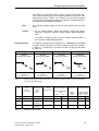
3.1.2.4 Velocity setpoint for local operation
The standard axial winder software package has, in the local operating
mode, its own setpoints system with a separate (override) ramp-function
generator. Depending on the selected local operating mode, the
corresponding setpoint is switched-through. The override ramp-function
generator is in this case always effective after an operating mode change
(block diagram 18). The ramp-up and ramp-down times are set together
using H161. The presently active setpoint can be monitored using d344.
It is possible to toggle between closed-loop speed / velocity control and
local operation using H146 = 0/1.
Axial winder SPW420- SIMADYN D -Manual
6DD1903-0AB0 Edition 07.99
27
Function description
Local operating
modes
The following operating modes are available:
• “Local run“ (H052)
Setpoint selection via H075 (b.d. 11)
(block diagr. 16/17)
• “Local crawl“ (H039)
Crawl setpoint = H142
• “Local positioning“(H026)
Setpoint is selected via H091 (b.d. 12),
X 2/X3 characteristic, selected using H163
• “Local inching, forwards“(H038),
inching setpoint = H143
• “Local inching, backwards“(H040), inching setpoint = H144
Control signals
Local operation must be enabled via the ”Local operator control” control
signal H027. A dedicated control signal is available for each local
operating mode. The commands are ”latching”, i.e. they are internally
saved. The commands are mutually interlocked, so that only one is
effective at any one time. In order to exit the run, crawl and positioning
modes, the “Local stop” command H028 or the ”Local operator control”
signal must be withdrawn; refer to Chapter 3.3.4.
Note
When setting-up a local operating mode, the base drive is powered-up
(main contactor) and operation is automatically enabled after the drive
ready status has been signaled back.
Caution
The "local operator control" control signal H027 must remain active until
the basic drive shuts down. Otherwise the motor will coast down.
Inching
When inching, the pulse enable in the base drive is extended by a time
which can be parameterized using H014. Before this time expires, the
inching setpoints can be changed as often as required, by activating the
inching commands. It is also possible to change into another local mode
during this time.
Mixed operation
For system operation, it is possible to input the local setpoints using
H166 = 1. In this case, only the appropriate setpoint is switched-through
with the local control signals, and added to the velocity setpoints; refer to
Chapter 3.3.4.
Parameter Parameter name
Explanation
H014
Inching time
Refer to Chapter 5
H026
Source, local positioning
Command, local positioning (H091, H163)
H027
Source, local operator control
Command, local operator control, refer to Chapter 5
H028
Source, local stop
Command, local stop
H038
Source, local inching forwards
Command, local inching forwards (H143)
H039
Source, local crawl
Command, local crawl (H142)
H040
Source, local inching backwards
Command, local inching backwards (H144)
H052
Source, local run
To power-up with the local setpoint (H075)
H075
Source, setpoint local operation
Refer to Chapter 5 (H052)
H091
Source, positioning ref. value
Refer to Chapter 5 (H026, H163)
H142
Setpoint, local crawl
Setpoint for the local crawl operating mode (H039)
H143
Setpoint, local inching forwards
Setpoint for the local inching forwards mode (H038)
H144
Setpoint, local inching backwards
Setpoint for the local inching backwards mode (040)
H146
Closed-loop speed control for local
Changeover between closed-loop speed or velocity
28
Axial winder SPW420 - SIMADYN D - Manual
6DD1903-0AB0
Edition 07.99
Function description
operation
control, refer to Chapter 5
H161
Ramp-up/ramp-down time
Ramp times for the override local ramp-fct. generator
H163
Select positioning reference value
Refer to Chapter 5 (H026, H091)
H166
Enable addition of local setpoints
Refer to Chapter 5
d344
Velocity setpoint
This is used to calculate the speed setpoint
Table 3-4
Parameters to the setpoint for the local operating modes
3.1.2.5 Limiting the velocity setpoint
Effective,
only for H203 < 2
The velocity setpoint is limited for the direct and indirect tension control
(closed-loop) via the torque limits. Therefore, the following is possible:
a
Velocity setpoints which are not required can be suppressed (e.g.
for a rewinder);
b
Automatic web sag protection using overcontrol.
3.1.2.6 Winder overcontrol
In order to prevent that a full roll accelerates up to an inadmissible speed
when the web breaks, the setpoint of the web velocity is divided by the
diameter calculated when winding. This means that the speed controller
is supplied the correct speed setpoint, which in turn results in the fact
that the circumferential velocity of the roll coincides with the web
velocity. In order to be able to develop a motor torque for operation with
the closed-loop torque limiting control, parameter H145 is added to the
actual setpoint as saturation setpoint. Thus, it is ensured that the drive
remains torque controlled, when the material web is intact (the speed
controller is overcontrolled with the correct sign) . When the material web
breaks, the motor only accelerates by the supplementary value of the
basic speed setpoint (saturation setpoint). For most of the applications,
H145 is set between 0.05 and 0.10 .
Parameter Parameter name
Explanation
H044
Source, polarity saturation
setpoint
To changeover the polarity of the saturation setpoint.
H145
Saturation setpoint
Supplementary setpoint for the velocity setpoint for the
closed-loop torque limiting control
H164
Smoothing, saturation setpoint
Smoothing time for the saturation setpoint
d341
Actual saturation setpoint
Display parameter
Table 3-5
Overcontrol parameter
3.1.3 Setpoint for the closed-loop tension / position controller (block
diagram 7/8)
Main tension
setpoint
The setpoint source is selected using H081. For closed-loop position
controls using a dancer roll, a fixed position reference value can be
entered with the standard connection via parameter H080.
Axial winder SPW420- SIMADYN D -Manual
6DD1903-0AB0 Edition 07.99
29
Function description
Ramp-function
generator
Winding hardness
characteristic
The main tension setpoint can be fed through a ramp-function generator
with ramp-up and ramp-down times which can be parameterized, H175
and H176. For applications using a dancer roll (H203= 2 or 3), we
recommend that a ramp-function generator should be used, i.e. H284=0.
Otherwise, the ramp-function generator can be disabled, i.e. H284=1.
H206 is used to select whether the subsequent winding hardness
characteristic is applied. The supplementary tension setpoint is added
after the characteristic; the source is selected via H083.
The resulting total setpoint can be smoothed again using H192, and is
available at d304 as display parameter.
Parameter Parameter name
Explanation
H080
Fixed value, tension setpoint
Enters the fixed value via a standard connection
H081
Source, tension setpoint
Refer to Chapter 5
H082
Fixed value, suppl. tension setp.
Enters the fixed value via a standard connection
H083
Source, suppl. tension setpoint
Refer to Chapter 5
H175
Ramp-up time, tension setpoint
Refer to Chapter 5
H176
Ramp-down time, tension setp.
Refer to Chapter 5
H192
Smoothing, tension setpoint
Smoothing time constant for the total setpoint
H206
Select winding hardness charact.
Refer to Chapter 5
H284
De-activate ramp-function gen.
Refer to Chapter 5
d304
Sum, tension setpoint/position reference
value
Display parameter
Table 3-6
Parameters for the setpoint tension/position control
3.1.3.1 Winding hardness control (block diagram 7)
Purpose
The winding hardness control reduces the tension as the diameter
increases. Generally, it is only used for winders to ensure that the inner
layers are more tightly wound.
Dancer roll
For closed-loop dancer controls, the position reference value is entered
as supplementary tension setpoint. The output of the characteristic,
available as d328, can be output at one of the analog outputs as setpoint
for the dancer roll support (H177=1), when required.
Generating the
characteristic
The winding hardness characteristic is realized as a parameterizable
polygon characteristic with 5 points. The actual diameter and the main
tension setpoint after the ramp-function generator are the input signals.
The source for the maximum tension reduction, referred to the setpoint,
can be freely selected using H087. The tension setpoint starts to
decrease, if the diameter reaches the value set at H183. It follows the
parameterized characteristic, which is set using the parameters shown in
the block diagram (block diagram 7). The diameter values D and D1 - D4
for parameters H183 to H187 must be set in an increasing sequence.
The tension reductions for diameters D1, D2 and D3 are specified using
H180, H181 and H182; and, more precisely, as a % value of the
maximum tension reduction.
30
Axial winder SPW420 - SIMADYN D - Manual
6DD1903-0AB0
Edition 07.99
Function description
Example 1
Tension setpoint for D1 = main setpoint - (maximum tension reduction
main setpoint * H180)
Example 2
With the standard link from H087 and H086=0.60, H086 is parameterized
as fixed value for the maximum tension reduction. The main tension
setpoint is 0.50. The winding hardness characteristic then has the
following characteristics:
*
a)
If the diameter is less than or equal to the initial diameter for the
start of tension reduction, set in H183, then the output of the winding
hardness characteristic is 0.5.
b)
If the diameter is greater than or equal to the final diameter H187,
then the output of the winding hardness characteristic is 0.20.
c)
If the diameter lies between the initial diameter H183 and the final
diameter H187, then the output follows the programmed winding
hardness characteristic, and has values between 0.50 and 0.20.
If a decreasing winding hardness is not required, e.g. for unwinder, then
parameter H206 must be set to 1.
Note
Parameter
Parameter name
Explanation
H086
Fixed value, maximum tension reduction
Fixed value is entered
H087
Source, maximum tension reduction
Refer to Chapter 5
H177
Inhibit tension setpoint
Only for dancer rolls, refer to Chapter 5
H180
Tension reduction 1 at D1
Refer to Chapter 5
H181
Tension reduction 2 at D2
Refer to Chapter 5
H182
Tension reduction 3 at D3
Refer to Chapter 5
H183
Diameter at the start of tension reduction
Refer to Chapter 5
H184
Diameter, D1
Refer to Chapter 5
H185
Diameter, D2
Refer to Chapter 5
H186
Diameter, D3
Refer to Chapter 5
H187
Diameter, D4 at the end of tension reduction
Refer to Chapter 5
H192
Smoothing, tension setpoint
Smoothing time for the tension setpoint
H206
Select, winding hardness characteristic
Refer to Chapter 5
d328
Table 3-7
Tension setpoint after the winding hardness ch.
Parameters for the setpoint, tension/position controller
3.1.3.2 Standstill tension (block diagram 7)
Standstill
identification
(block diagram 6)
When the winder is at a standstill, it is possible to changeover from the
standard operating tension to the standstill tension using the command
”Standstill tension On” with H188. The prerequisite is that the standstill
limit H157 has been fallen below and that a delay time, H159, has
expired.
Axial winder SPW420- SIMADYN D -Manual
6DD1903-0AB0 Edition 07.99
31
Function description
Standstill setpoint
The standstill setpoint can be selected from the following:
H188 = 1 & H191 = 0
The standstill setpoint is a fixed value, which
can be set with H189
H188 = 0 & H191 = 0
The standstill setpoint is a percentage value of
the operating tension setpoint, and is set using
H189.
H188 = 1 & H191 = 1
The standstill setpoint is an operating t ension
setpoint, or is the fixed standstill tension
setpoint, set at H189, depending on which of
the two values is the lower.
H188 = 0 & H191 = 1
Illegal operating status.
Parameter
Parameter name
Explanation
H157
Limit value for the standstill identification
Refer to Chapter 5
H159
Delay, standstill identification
Delay time before the standstill signal is issued
H188
Source, standstill tension
Operating status, refer above
H189
Standstill tension
Enter the fixed value
Minimum selection
Refer to Chapter 5
H191
Table 3-8
3.2
Parameters for the setpoint, tension/position controller
Sensing actual values
3.2.1 Selecting the speed actual value (block diagram 13)
The axial winder requires the speed actual value to calculate the
diameter. There are five possibilities to transfer the speed actual value to
the T400:
Source
• Directly via the T400 interface (pulse encoder 1)
• Via the CU backplane bus
• Actual value W2 received from the CU
• Analog inputs of T400
• Via the T400 interface (pulse encoder 2)
The actual speed can be monitored at display parameter d307 as a
percentage of the maximum motor speed.
Parameterization
Table 3-9 summarizes all of the parameters which have to be set for the
speed actual value acquisition:
Parameter
Parameter name
Explanation
H092
Source, speed actual
value
Freely connectable from the source
32
Axial winder SPW420 - SIMADYN D - Manual
6DD1903-0AB0
Edition 07.99
Function description
H165
Smoothing, speed act.
value
Smoothing time, speed actual value
H212
Encoder pulse number,
axle-mounted tachometer
Number of pulses per revolution
H214
Rated speed, winder drive
100% maximum speed at the minimum diameter and maximum
web velocity, refer to Chapter 5.
H217
Operating mode sensing
16#7FC2 encoder signals from the CU via the backplane bus
(refer to Chapter 5)
P151(CUVC)
Pulse number, shaft
tachometer
same as for H212,
P353(CUVC)
Rated speed, shaft
tachometer
same as for H214, refer to Table 6-1
d307
Speed actual value
Display parameter
16#7F02 encoder signals from terminal 72-75 of the T400
Table 3-9
refer to Table 6-1
Parameters for the speed actual value sensing
Example
Pulse encoder at the base drive with 1024 pulses/ revolution, speed at
Vmax
and
core
diameter:
2347RPM:
H212= P151=1024,
H214=P353=2347, H217=7FC2
Caution
Any changes made at H212, H214 and H217 will only become effective
after the system has first been powered-down and then powered-up
again.
Note
We recommend that the speed actual value is taken directly from the CU
(H092=550), as in this case, only the parameters in the CU have to be
set. Otherwise, the parameters from T400 (H212, H214 and H217) and
from the CU (P151 and P353 for CUVC), must be set, as long as the
speed controller in CU is used, refer to Table 6-1.
3.2.2 Speed actual value calibration
The speed actual value calibration for the winder must always be
executed with the standard gearbox ratio:
When a velocity setpoint is entered (preferably 1.0), without web velocity
compensation and without saturation setpoint (closed-loop tension
control disabled!), the actual value measured at the winder shaft, must
correspond with the entered setpoint. The actual diameter available in
the closed-loop control (d310) must be identical with the mechanically
measured diameter of the winder shaft. It is practical if the core
diameter is adjusted with an empty mandrel.
Procedure
Depending on the source (CU or T400, refer to block diagram 13), of the
speed actual value sensing, the appropriate parameters are set in the
basic drive (Pxxx) or T400 (Hxxx). For each of the following points,
check the speed actual value:
• Enter the core diameter H222
• Select the core diameter as the diameter setting value, H89 =
KR0222
Axial winder SPW420- SIMADYN D -Manual
6DD1903-0AB0 Edition 07.99
33
Function description
• Issue the ”Set diameter” command (activate H024 =B2001
minimum pulse duration 100 ms)
1) Using a digital tachometer
• Enter the number of pulses per revolution at H212
appropriate parameters in the basic drive.
and/or the
• Specify the rated motor speed (min. diameter, max. velocity
and normal gearbox ratio: Vmax * 1000 * i / (D core * Π)) at H214 and/or
Pxxx.
• Select the encoder mode with H217 , if H092=219.
2) Using an analog tachometer
• Speed actual value from base drive converter (e.g. for CUVC
P734.02=148, H092=550 )
• Calibrate the speed actual value at the basic drive converter
with P138 (in CUVC); in case of the limited voltage ( ± 10V) at
analog inputs of base drive, an ATI board is required.
• When an analog tachometer is used (in CUVC, P130=13/14),
the related parameters must be set according to the Instruction
Manual.
• Check, if v act (measured value from a handheld tachometer)
v*
=
If the gearbox ratio is not precisely known, the parameter H214 /Pxxx
should be so calibrated, until v act equals v * (at D=D core ). The
correspondence should be checked at various web velocity setpoints up
to 1.0.
Note
If parameters H212, H214 and H217 on the T400 are changed, they only
become effective after the electronics power supply of the converter has
been switched-off and -on again , refer to Chapter 3.2.1 .
Parameter Parameter name
Explanation
H022
Source, tension controller on
Refer to Chapter 5
H088
Diameter setting value
Fixed value, diameter setting value
H089
Source, diameter setting val.
Refer to Chapter 5
H222
Core diameter
Dcore /Dmax .
d310
Actual diameter
Display parameter
Table 3-10 Parameters to celebrate the speed actual value
3.3
Control
3.3.1 Control signals (block diagrams 16/17/22b)
Control bits
34
The source for the control commands required for the particular
application can be freely selected. The individual commands can be
entered from the COMBOARD, the base drive, via a peer-to-peer
Axial winder SPW420 - SIMADYN D - Manual
6DD1903-0AB0
Edition 07.99
Function description
coupling or via the digital inputs of the T400. The individual control word
bits are assigned to fixed control commands; the same is true for T400
terminals 53 to 60 (block diagram 17). For these 8 fixed control signals
(refer to Table 2-8), it is possible to toggle between control via T400
terminals and input via a control word (from the COMBOARD or the
peer-to-peer link).
Parameterization
The control commands are selected via appropriate parameterization
and BICO-technology or Service-IBS program. The digital inputs
(terminals 53 to 60 ), the appropriate bit of the possible control words and
fixed values 0 and 1 are available as sources. Control bits, which are not
included in the control words, can be addressed as dedicated
parameters.
Monitoring
All of the possible control commands for winders are combined, for
diagnostic purposes, in 3 display parameters (d332, d333 and d334).
These parameters indicate the status of the control signals directly
before internal processing.
3.3.2 Winding direction
To change the direction of the motor rotation, the ”Winding from below”
command can be activated (block diagram 5/6/9b). This reverses the
polarity (sign) of the speed setpoint signal for all operating modes
(including reverse winding after the splice) (refer to Fig. 3-2). This
change also activates the override ramp-function generator.
Winding from
“above” or
“below”
+
+
+
W inding from above
Fig. 3-2
Note
W inding from below
Sketch of the winding direction
The ”Winding from below” command should only be activated, if both
modes are really operationally required. Otherwise, “Winding from above
should always be selected, independent of the web path.
3.3.3 Gearbox stage changeover (block diagram 5)
Several gearbox
stages
The configured software allows you to changeover to a second gearbox
stage which has been expanded using BICO technology . This is normally
used in order to achieve a higher web tension with the same motor
output, but at a lower web velocity. For instance, this is required for
thicker materials. H042 is used to select the changeover signal, and the
Axial winder SPW420- SIMADYN D -Manual
6DD1903-0AB0 Edition 07.99
35
Function description
ratio between the standard gearbox stage and gearbox stage 2 must be
entered by selecting H138 or the fixed value of H127 .
Operation with gearbox stage 2, for the same motor speed, means that
the winder shaft rotates at a lower speed. The influence of gearbox stage
2 on the velocity setpoint, moment of inertia, diameter computer and the
inertia compensation as well as reverse winding after a splice, is
automatically taken into account by the winder software. The friction
torque characteristic can be adapted using parameter H229 (source) or
H128 (fixed value) .
The influence of gearbox stage 2 on the velocity setpoint, is effective in
system operation, local operation and reverse winding after a splice.
Formula for H127
Example
H127 =
Speed
Speed
winding motor
winding motor
Standard gearbox ratio
Gearbox ratio 2
* 100 %
/ speed winder shaft = 5 / 1 for the standard gearbox stage
/ speed winder shaft = 7 / 1 for gearbox stage 2
H138=KR0127; H127 = 5 / 7 * 100 % = 71.4% = 0.714
3.3.4 Two operating modes (block diagram 18)
General
There are two operating modes for the winder: System operation and
local operation. It is not possible to toggle between the modes
without shutting down. The changeover between these two modes is
realized using the ”Local operator control” command, either via fixed
value binector (B2000/B2001) or terminal 59 or via control word 2 bit 5
from the COMBOARD; the source is selected using H027. The operating
modes are mutually interlocked, i.e. if the “Local operator control” signal
level changes during operation, then the system is always shutdown.
System operation
This mode is selected using the Off1/On = 1 (H045) control signal. The
power-on command is transferred to the base drive, the main contactor
is closed, and the DC link is charged. When the base drive sends a
checkback signal indicating that the drive is ready, the winder waits for
the operating enable (block diagram 18) from the ”System start” H021,
and, after being enabled, accelerates to the setpoint; refer to Chapter
3.1.2.
The ”Off1/On” = 0 control signal must be set to 0 to power-down the
system. When the winder comes to a standstill (zero speed), the base
drive is powered-down; if the winder is still running, the velocity setpoint
is set to 0. The system is shutdown when the standstill limit has been
fallen below. Only then is the "System start" control signal switched-out.
Caution
The winder can only be operated in the closed-loop tension controlled
mode in system operation.
The "system start" control signal H0121 must remain active until the
basic drive is powered-down, otherwise the motor coasts down.
Local operation
36
Axial winder SPW420 - SIMADYN D - Manual
6DD1903-0AB0
Edition 07.99
Function description
In order to select a local operating mode, the ”Local operator control”
control signal H027 must be 1. The run, crawl and positioning operating
modes are activated with a positive edge of the appropriate control
signal, and are internally stored. For inching, the operating mode only
remains active as long as the appropriate control command is present.
The operating modes are mutually interlocked, i.e. only one can be
active at any one time.
When an operating mode is switched-in/out, the associated setpoint is
transferred to the closed-loop control via the override ramp-function
generator. At each operating mode change the ramp-function generator
will first be set to the actual value. This is realized both when switching-in
as well as when switching-out. For the base drive, a power-on command
is generated to close the main contactor. Operation is automatically
enabled when the drive signals back a ready signal. This also sets the
override ramp-function generator.
In the inching mode, the winder operates with the appropriate setpoint
only as long as the inching command is active. After this, the drive
remains powered-up for a time which can be set using H014. The drive
automatically shuts down when the delay time expires.
It is possible to disable all of the local operating modes with ”Local stop”
H028, or by withdrawing the ”Local operator control” H027. The winder
decelerates to a web velocity of 0.0, and after the standstill limit is fallen
below, it shuts down.
The local setpoints refer, as standard, to the web velocity. It is possible
to changeover to the closed-loop speed control mode with H146 = 1;
refer to Chapter 3.1.2.4.
• “Local run“
Select the source for the control command using H052.
Select the source for the setpoint using H075; pre-setting H075
=KR0074= 0.0.
• “Local crawl“
Select the source for the control command using H039.
The crawl setpoint is entered with H142, pre-setting 0.1.
• “Local inching, forwards/backwards“
The source of the inching forwards/backwards command is selected
using H038 or H040.
The setpoints are set using parameters H143 and H144, and, as
standard +0.05 and –0.05.
In the inching modes, the drive only moves with the selected setpoint
for the time that the control command is present.
Note
It is possible to changeover from the inching mode into any other
local operating mode, without powering-down the drive.
• “Local positioning“
The source of the positioning command is selected using H026.
The source of the positioning setpoint is selected using H091. The
Axial winder SPW420- SIMADYN D -Manual
6DD1903-0AB0 Edition 07.99
37
Function description
setpoint is used internally as X 2 or X 3 characteristic, changeover using
H163.
For all of the local operating modes, the setpoint is changed using the
internal override ramp-function generator. The ramp-up and ramp-down
time is entered using H161, and refers to a 1.0 setpoint.
Parameters
Mixed operation
Refer to Table 3-3 and Table 3-4.
Using H166 = 1, it is possible, in system operation, to add the local
setpoints with the tension control enabled, to the velocity setpoint. For a
velocity setpoint of 0.0, for example, the appropriate inching setpoint can
be entered via the override ramp-function generator, using the ”Inching
forwards” command. It is possible to add each individual local setpoint
with the appropriate command. The same interlocking conditions apply
as for the local operating modes. A change, for example, from closedloop tension controlled inching into winding operation, can be easily
realized via the “Enable setpoint” control input of the central rampfunction generator.
3.3.5 Motorized potentiometer functions (block diagram 19)
Two motorized
potentiometers
Motorized
potentiometer 1 as
additional rampfunction generator
H267=1
Motorized
potentiometer
function
The winder software package has two separate motorized potentiometer
functions. Their outputs can be used everywhere as setpoints.
Motorized potentiometer 1 can be additionally parameterized as rampfunction generator to generate defined ramps during start-up, e.g. for
inertia compensation. The ramp-function generator mode is enabled with
H267 = 1, the setpoint is parameterized with H268, and the rampup/ramp-down time with H269. The ramp-function generator ramps-up to
the entered setpoint with the ”Raise motorized potentiometer 1”
command H030; with ”Lower motorized potentiometer 1” H032, it is
ramped-down towards 0.0.
For the motorized potentiometer function, the appropriate output can be
changed with the raise or lower control inputs. It the commands are
briefly activated (< 300ms), the output is changed bitwise. When it is
actuated for a longer period of time, it changes with the ramp-up/rampdown times, parameterized with H265 for motorized potentiometer 1, and
with H263 for motorized potentiometer 2. If the control commands are
present for longer than 4 s, the ramp-up/ramp-down ramps are changed
over to H266 (Mop 1) and H264 (Mop 2). The outputs of the motorized
potentiometers are available as monitoring/visualization parameters
d305 and d306.
Param.
Parameter name
Explanation
H029
Source, raise motorized potentiometer 2
Command, raise motorized potentiometer 2
H030
Source, raise motorized potentiometer 1
Command, raise motorized potentiometer 1
H031
Source, lower motorized potentiometer 2
Command, lower motorized potentiometer 2
H032
Source, lower motorized potentiometer 1
Command, lower motorized potentiometer 1
H263
Motorized potentiometer 2, fast change
The fast change starts, if the raise or lower control
commands are present for longer than 4s.
H264
Motorized pot. 2, standard change
Ramp-up- and ramp-down times
38
Axial winder SPW420 - SIMADYN D - Manual
6DD1903-0AB0
Edition 07.99
Function description
H265
Motorized pot. 1, fast change
As for H263
H266
Motorized pot. 1, standard change
As for H264
H267
Select mode, motorized potentiometer 1
0: mot. potentiometer; 1: ramp-function generator
H268
Setpoint, ramp-funct. gen. operation
Refer to Chapter 5
H269
Ramp time, ramp-funct. gen. operat.
Refer to Chapter 5
d305
Output, motorized potentiometer 1
Display parameter
d306
Output, motorized potentiometer 2
Display parameter
Table 3-11 Parameters for the motorized potentiometer functions
3.3.6 Splice control (block diagram 21)
Purpose
The splice logic allows the drive functions to be controlled for a flying roll
change. The closed-loop tension control, fast stop, reverse winding after
a splice and synchronization are implemented on the T400. The
sequence control for the automatic splice functions (mechanical rotation,
power-up commands for synchronizing and splicing, controlling the glue
roll and knife) must be realized in a PLC control.
Sequence
The splice control is activated via H148 (reverse winding time) as soon
as a value not equal to zero is entered there. Further, the ‘Tension
controller on’ command (H022) must be set to one of the other two
connections ( B2011/B2012 refer to block diagram 17), dependent on
whether the command to switch-in the tension controller is received from
the terminal or via a control bit. When splicing, only the 'splice enable '
signal is used to activate the tension controller and the 'tension controller
on' command must be inactive. For the very first r oll, the "tension
controller on" signal is used to activate the tension controller The
setpoint for the reverse winding function is entered at H149 (the value
must be negative!); refer to Fig. 3-3.
To sense a new diameter, a diameter must first be set (e.g. the average
value from the highest- and lowest possible diameter for a splice). The
new reel is then powered-up with a local operating mode and runs at a
low speed. The tachometer is then applied and this is signaled using a
digital signal. The diameter computer is enabled and calculates the
actual diameter of the new roll. The drive is then shutdown again
(powered-down).
The swiveling mechanism is rotated into the changeover position for
splicing, refer to Fig. 3-4. The drive with the new roll is powered-up
again. If it is running in system operation, it synchronizes to the web
velocity. The ’Tension controller on’ signal (from the terminal or via the
control bit) must be inactive. However the drive still remains in the
closed-loop speed control mode until the ’Knife in the cutting position’
signal becomes active. It then switches-over to closed-loop tension
controller. The partner drive, which was previously in the closed-loop
tension control mode, goes into a fast stop. Depending on the
parameterization of H148/149, it rotates backwards for some time before
it shuts down.
Axial winder SPW420- SIMADYN D -Manual
6DD1903-0AB0 Edition 07.99
39
Function description
L oading
position
2
Swiveling mechanism
1
Glue roll
Splice knife
T ension measurement
T achometer
Fig. 3-3
Loading position when splicing
A connection must be established from the ’Tension controller on’ output
to the ’Partner drive is in the tension controlled mode’ input of the partner
so that the drives can be mutually interlocked. The pre-assignments of
these signals refer to block diagram 17.
C h a n g eo v er
1
p o siti o n
Swiveling mechanism
Glue roll
2
Splice knife
Tension measurement
T achometer
Fig. 3-4
Note
Change position when splicing
The splice functions are only provided for relatively simple requirements.
The actual functions to be implemented must be precisely clarified with
the manufacturers of the mechanical design of the splice mechanism. If
you have any doubt, please contact your local SIEMENS office.
Parameter
Parameter name
Explanation
H022
Source, tension controller on
Refer to Chapter 5
H148
Time for reverse winding after a splice
Refer to Chapter 5
H149
Speed setpoint, reverse winding after a splice
Refer to Chapter 5
H169
Knife in the cutting position
Refer to Chapter 5
H170
Partner drive is in the closed-loop tension control mode
Refer to Chapter 5
Table 3-12 Parameters for the splice control
40
Axial winder SPW420 - SIMADYN D - Manual
6DD1903-0AB0
Edition 07.99
Function description
3.4
Closed-loop control
3.4.1 Closed-loop control structure (block diagram 4)
Control technique
An overview of the complete closed-loop control structure is provided in
Sheet 4 of the block diagram . The closed-loop tension control,
characteristic for the winder, influences the speed controller in the
converter in three different ways. A specific winding technique is defined
using parameter H203.
Closed-loop torque
limiting control
For the closed-loop torque limiting control, the higher-level tension
controller acts on the speed controller limits, and thus maintains the
required web tension. Compensating torques for friction and inertia
compensation are generated as pre-control values which are added in
front of the torque limiting, with the correct sign. With this control
method, the speed controller is kept at the torque limits, by entering a
saturation setpoint. Further, the velocity setpoint is limited. This means
that the winder automatically goes to the saturation setpoint if the web
breaks or the web sags.
Closed-loop speed
correction control
When the closed-loop speed correction control is selected, a cascadetype structure is obtained. The tension controller influences the speed
controller setpoint. The compensation torques are added as
supplementary torque setpoint after the speed controller in the base
drive (CU).
Closed-loop
constant v control
For the closed-loop constant v control, the tension controller is disabled
(output limiting = 0.0 using parameter H195) and the winder operates
with the specified web velocity setpoint, e.g. as the master drive of a
rewinder.
3.4.2 Closed-loop speed control (block diagram 6/6a)
External or internal
H282
Note
The univer sal applicability of the T400 allows closed-loop speed control
to be implemented in two ways. The closed-loop speed control is
either externally implemented in the connected drive converter, or is
internally executed on the T400 processor module for stand alone
operation in the SRT 400. One of these alternatives is selected using the
“Speed controller changeover to CU or T400“ option, which can be set
using parameter H282.
Parameter H282 is preset to 0, i.e. the speed control is executed in the
drive converter. The standard axial winder software package specifies
the speed setpoint, influences the torque limits and outputs a
supplementary torque setpoint for the necessary compensation functions.
3.4.2.1 Influence of the speed controller (block diagram 6)
For closed-loop tension controlled operation, either the speed controller
limits (torque limiting control) are influenced, or the speed setpoint
(speed correction control). It is possible to adapt the gain to the variable
moment of inertia. The controller is set at start-up using automatic
optimization routines.
Axial winder SPW420- SIMADYN D -Manual
6DD1903-0AB0 Edition 07.99
41
Function description
3.4.2.2 Kp adaptation (block diagram 6a)
Mode of operation
The controller gain is adapted to the variable moment of inertia on the
T400 or in the drive converter using a polygon curve which can be
parameterized. The quantity is the calculated variable moment of inertia;
the output acts on the proportional gain of the controller on the T400 or in
the drive converter, depending on the setting of parameter H282. The
starting- and end points of the adaptation should be set together with the
associated controller gains. The characteristic is linearly interpolated
between these two points.
Parameterization
The Kp values for a full and an empty reel are required for the correct
setting. These are determined at start-up (when the drive is being
commissioned).
Setting parameters:
Kp min
H151
Controller gain for an empty roll
Kp max
H153
Controller gain for a full roll
Jv start
H150
Starting point of adaptation, generally at 0.0
Jv end
H152
End point of adaptation, generally at 1.0
When determining the controller gain with, as far as possible, a full reel,
the associated variable moment of inertia can be read as visualization
parameter d308, or can be calculated using the known diameter. The
following is valid for gearbox stage 1, material density and width: J v [%] ≈
D4 [%] – Dcore 4 [%]. The value, entered as H153, must be referred to
100% Jv, i.e.
On the T400
H282=1
Kp max = determined K p * 100% / determined J v [%].
For the basic winder setting, with H151=H153, adaptation is disabled.
The actual adaptation value is displayed using d345.
For H282=0, the values must be set in the base drive as shown in Table
3-13. The speed controller optimization run of the basic drive can be
used.
In the converter
H282=0
Parameter
Value
Explanation
CUVC/CUMC
CUD1
T400
P233 (0%)
P556 (0%)
H150 (0.0)
Start of adaptation J v start
P234 (100%)
P559(100%)
H152 (1.0)
End of adaptation J v end
P235
P550
H151
Kp adaptation min.
P236
P225
H153
Kp adaptation max.
Table 3-13 Parameters for the Kp adaptation in the drive converter
Note
We recommend that the kp adaptation is commissioned for winding
ratios >3, otherwise the basic setting should be used, H151=H153=1 and
P235=P236 =100% for CUVC.
Param. Parameter name
Explanation
H150
Start of adaptation J v start
First point of intervention of the Kp adapt., generally 0.0
H151
Kp adaptation min.
Kp for an empty reel, generally 1 .0
42
Axial winder SPW420 - SIMADYN D - Manual
6DD1903-0AB0
Edition 07.99
Function description
H152
End of adaptation J v end
Last point of intervention of the Kp adaptation, generally
1.0
H153
Kp adaptation max.
Kp for a full roll
H162
Smoothing, speed controller output
Smoothing for the visualization parameter d331
H282
Changeover to the speed controller on
CU or T400
H282 = 0 speed controller on CU
H290
Upper speed setpoint limiting
If H282=1
H291
Lower speed setpoint limiting
If H282=1
H292
Ramp-up time, speed setpoint
If H282=1
H293
Ramp-down time, speed setpoint
If H282=1
H294
Integral action time, speed controller
(H282=1)
For the speed controller on T400
d308
Variable moment of inertia
Display parameter
d329
Torque setpoint calculated from T400
Display parameter, if H282=1
d331
Smoothed torque setpoint calculated
from T400
Display parameter, if H282=1
d345
Actual Kp adaptation from T400
Display parameter
H282 = 1 speed controller on T400
Table 3-14 Parameters for the speed controller on T400
3.4.3 Closed-loop tension / dancer roll – position control (block diagram
7/8)
Control methods
H203 = 0
In order to control the material tension, for the standard axial winder
software package, five different control techniques are implemented.
H203 is used to select one of the following possibilities:
Indirect closed-loop tension control with direct open-loop torque control
via the torque limit values.
This is the preferred solution for indirect closed-loop tension control.
H203 = 1
Direct closed-loop tension control using a tension transducer, whereby
the tension controller regulates the torque via the torque limit values.
This is the preferred solution if a tension transducer is used.
H203 = 2
Direct closed-loop tension control using a dancer roll potentiometer as
tension actual value generator. The dancer roll closed-loop position
controller regulates (open-loop) the torque via the torque limit values.
This control technique is seldomly used; it may, under certain
circumstances, be practical for extremely sensitive brittle or hard
materials which are not very flexible, e.g. cables, textiles, paper etc.
H203 = 3
Direct closed-loop tension control using a tension transducer or a dancer
roll potentiometer as tension actual value generator, whereby the tension
controller acts on the speed controller via a speed correction setpoint.
This control technique should be used if a dancer roll is used. If there is a
tension transducer, then this control technique is occasionally used for
elastic, extremely expandable materials, e.g. thin plastic foils.
Axial winder SPW420- SIMADYN D -Manual
6DD1903-0AB0 Edition 07.99
43
Function description
H203 = 4
Presently not used; free for making expansions.
H203 = 5
As for H203=3, however the tension controller output can be multiplied
by the web velocity signal. With parameter H201, the ”lower limit value”
is defined for the multiplying effect of the web velocity on the tension
controller output. It can be normalized using parameter H202.
Tension/position
controller
Note
The tension controller is a proportional-integral differential controller
(PID), whose integral action time and differentiating time constant can be
set using parameters H199 and H173. With H196 = 1 and H283=0, the
controller acts as a pure proportional controller or proportional-differential
controller, depending on the setting H174 (inhibits the D controller). If a
dancer roll is used, then the tension controller operates as dancer roll
position controller.
For applications with tension transducer or dancer roll in the ”speed
correction” mode (H203 = 3 or 5), the tension controller is operated as
usual as proportional-differential controller (PD). I.e. H174=0, H196=1
and H283=0. For applications with the tension transducer via the torque
limits (H203=1) the tension controller is normally used as proportionalintegral controller (PI).
Limiting the
tension controller
The output signal of the tension controller is limited depending on the
setting of parameters H194 and H195:
H194 = 1
The output signal is limited to a positive value, which is set at H195.
Negative values are limited to zero. This setting is only practical when
using a 1Q drive for H203 = 0, 1 and 2.
H194 = 2
The output signal is limited to values between ±H195.
H194 = 3
The upper limit corresponds to the absolute speed actual value or a
minimum value which can be set with H193. The negative limit value is
zero.
H194 = 4
The upper limit value corresponds to the absolute speed actual value or
a minimum value which can be set with H193; the lower limit value,
corresponds to the inverted signal.
3.4.3.1 Kp adaptation
Analog to the speed controller, also here, the controller proportional gain
is adapted to the variable moment of inertia, which means that the
influence of the diameter, material width and density as well as a
possible gearbox changeover can be automatically taken into account.
Parameterization
Setting parameters:
Kp min
H197
Controller gain for an empty roll
Kp max
H198
Controller gain at 1.0 J
Jv start
H207
Start of adaptation, generally at 0.0
Jv end
H208
End of adaptation, generally at 1.0
v
When determining the controller gain with, if possible a full roll, the
associated variable moment of inertia can be read as display parameter
44
Axial winder SPW420 - SIMADYN D - Manual
6DD1903-0AB0
Edition 07.99
Function description
d308, or can calculated using the known diameter. The following is valid
for gearbox stage 1, constant material thickness and width: J v [%] ≈ D4
[%] – Dcore 4 [%]. The factor, which is entered as K p max , must be referred
to 100% J v , i.e.
Kp max = determined K p * 100% / determined J v [%].
For the basic winder setting, with K p min = Kp max , adaptation is not
effective and the actual value of K p is displayed using d346.
Note
We recommend that the kp adaptation is commissioned for winding
ratios >3.
3.4.3.2 D component of the tension controller (block diagram 7)
The differential component of the tension controller is used to
compensate the phase rotation, which is caused by an integral loop
element (dancer roll). If the tension is measured using a transducer, the
differential component must be disabled (H174=1), since the control loop
has PT1 characteristics.
For closed-loop dancer controls (H174=0, H196=1 and H283=0), without
or with a low derivative action time, the controller may oscillate. These
can be effectively suppressed by increasing H173.
Note
The duration of an actual value oscillation period without D-component is
a good approximation of the time constant of the differentiating (H173).
This value should not be exceeded. Instability can result if the time
constants are too high!
Parameter
Parameter name
Explanation
H173
Differentiating time constant
Refer to Chapter 5
H174
Inhibit D controller
1: no D control
H193
Min. value speed dependent tension
controller limits
Refer to Chapter 5
H194
Select tension controller limits
Refer above
H195
Adapt tension controller limits
Refer to Chapter 5
H196
Inhibit I-component, tension controller
1: PI controller --> P controller
H197
Min. Kp tension controller K
Controller gain for an empty roll
H198
Max. Kp tension controller K
H199
Integral action time, tension controller
For the tension controller I component
H200
Adaptation, setpoint pre-control
Refer to Chapter 5
H203
Selecting the tension control technique
Refer above
H207
Start of adaptation, tension controller J
H208
End of adaptation, tension controller J
H209
Droop, tension controller
Refer to Chapter 5
H283
I controller enable
1: PI controller -> I controller
H284
Deactivate ramp-function generator
0: for a dancer roll
d308
Variable moment of inertia
Display parameter
d317
Sum, tension controller output
Sum of the PI component on the D component
d318
Tension controller, D component
Display parameter
Axial winder SPW420- SIMADYN D -Manual
6DD1903-0AB0 Edition 07.99
p min
at H207
p max
at H208
v start
v end
Controller gain at 1.0 J
v
Start of adaptation, generally 0.0
End of adaptation, generally 1.0
45
Function description
d319
Tension controller output from the PI comp.
Display parameter
d346
Actual Kp adaptation
Display parameter
Table 3-15 Parameters for the tension controller
3.4.4 Generating the supplementary torque setpoint (block diagram 6/ 9b)
Compensation
In order to compensate for the friction losses and the torques when
accelerating/braking, the appropriate compensation factors are
calculated and are added to the torque setpoint with the correct polarity.
The winding direction, web routing, closed-loop control type, material
thickness and width as well as the gearbox stage changeover are
automatically taken into account.
This compensation influences the winder control in two different ways:
Pre-control torque
For closed-loop speed correction control, the pre-control torque is
injected as supplementary torque setpoint. The speed setpoint is entered
from T400, if H282= 0.
Torque limit
For the closed-loop torque limiting control, the compensation additionally
acts, in addition to the torque controller output, on the speed controller
limits. The drive converter parameterization required to realize this, is
specified in Chapter 6 (block diagram 3).
3.4.4.1 Compensation calculation (block diagram 9b)
Friction effect
The friction losses are compensated using a parameterizable polygon
characteristic with 6 points. This setting is made at start-up using
parameters H230 to H235 in 0.20 steps; refer to Chapter 7.2.2. The
outputs of the characteristic can be monitored using d314. For gearbox
stage 2, the characteristic output should be adapted by selecting H229 or
the fixed value of H128 .
Accelerating
torque
In order to compensate the accelerating torque, the variable moment of
inertia is calculated. In this case, diameter, material thickness (H224),
width (selected using H079) and a possible gearbox changeover
(selected using H138) are included. Together with the fixed moment of
inertia, after the actual diameter and the internal or external (H226)
acceleration signal have been taken into account, the pre-control torque
for inertia compensation is obtained, which is available at d316.
Note
The precise setting of the compensation factors is especially important
for indirect closed-loop tension control, so that the torque-generating
current results in, as precisely as possible, the material tension; refer to
Chapter 7.2.3.
The compensation factors for friction and acceleration are also effective
in the closed-loop speed controlled mode (e.g. for acceleration and
braking at roll change).
46
Axial winder SPW420 - SIMADYN D - Manual
6DD1903-0AB0
Edition 07.99
Function description
Param.
Parameter name
Explanation
H077
Source, external dv/dt
Refer to Chapter 5
H079
Source, web width
Refer to Chapter 5
H128
Fixed value, adapt friction torque, gearbox
stage 2
Refer to Chapter 5
H138
Source ratio, gearbox stage 2
Refer to Chapter 5
H224
Material density
The density of the material to be wound is specified
as a % of the maximum density.
H225
Fine adjustment, dv/dt
Refer to Chapter 5
H226
Source, dv/dt
Changeover between the internal or external value
H227
Adjustment, variable moment of inertia
Adjustment factor
H228
Constant moment of inertia
Refer to Chapter 5
H229
Source a daptation , gearbox stage 2
Refer to Chapter 5
H230
Friction torque at 0% speed
Absolute torque setpoint (d331) at n= 0%.
H231
Friction torque at 20 % speed
Absolute torque setpoint at n = 20%.
H232
Friction torque at 40% speed
Absolute torque setpoint at n = 40%.
H233
Friction torque at 60% speed
Absolute torque setpoint at n = 60%.
H234
Friction torque at 80% speed
Absolute torque setpoint at n = 80%.
H235
Friction torque at 100% speed
Absolute torque setpoint at n = 100%.
2
H237
Pre-control with n
Refer to Chapter 5
d302
Actual dv/dt
Display parameter
d308
Variable moment of inertia
Display parameter
d312
Pre-control torque
Sum of the friction- and acceleration effects
d314
Pre-control torque, friction compensation
Display parameter
d316
Pre-control torque, inertia compensation
Display parameter
Table 3-16 Parameters for compensation
3.5
Calculation
3.5.1 Diameter computer (block diagram 9a)
Principle
The diameter is computed from the velocity setpoint and the actual
motor speed. An integrating computation technique is used to generate
the smoothest output signal possible. The time for a computation interval
(time for one revolution at Dmin and Vmax) is specified using H216.
Alternative
technique
If the velocity setpoint signal is not available, the computation function
via H277 changes over to an alternative technique, which continues to
calculate the diameter, taking into account the revolutions and material
thickness. In this case, the thickness-diameter ratio (H286), the initial
diameter (H276) and the setting pulse duration (H278) are required. For
H277=1, the other technique runs in parallel in the background. The
actual diameter (in front of the ramp-function generator) can be taken via
connector KR0359.
Axial winder SPW420- SIMADYN D -Manual
6DD1903-0AB0 Edition 07.99
47
Function description
When an external web velocity actual value is used for the calculation,
this is selected using H094 (block diagram 13) and H211 must be set to
1. Gearbox changeover is automatically taken into account.
External V act
Web tachometer
When a digital web tachometer is used, parameters H213, pulse number,
H215, rated speed and H218 operating mode must be set for pulse
sensing on the T400; refer to Fig. 2-2 for the connection configuration.
When an analog web tachometer is used, an analog input is used to
sense the tachometer voltage.
Surface tachometer
The diameter computer can also be enabled without an active tension
controller, using a digital signal which can be selected with H013 (surface
tachometer function b.d. 9a). The web velocity actual value which is
used for the computation, can be selected using H093. This can be an
external analog tachometer as well as a pulse encoder, which is
connected instead of the web tachometer.
Ramp-function
generator
In order to increase the stability of the closed-loop control, the diameter
change can be limited per unit time using H238. H238 should be selected
so that the maximum change is still possible (this occurs at V max and
Dmin). The selected rate of change is automatically adapted to the actual
diameter.
Example
Core diameter D core = 140 mm,
Maximum diameter D
Maximum web velocity V
max
= 1000 mm
max
= 200 m/min = 3333 mm/s
Material thickness d=1 mm, i.e. 2 mm diameter increase / revolution
Minimum time for one revolution: t = H216 = D
core
* Π/ Vmax = 132 ms
This results in a maximum diameter change = 2*d / t = 15.15 mm/s.
This value is converted over the complete change (D
entered at H238.
max
– Dcore ) and
H238 = (D max – Dcore ) * t / (2 * d)
55 s is entered at H238 = 860 mm / 15.15 mm/s = 56.76 s, with a safety
factor of 5%.
Additional
interlocking
An additional interlocking can be enabled using H236. For H236=1, the
diameter of a winder can only increase, and for an unwinder, only
decrease. This interlocking function is canceled when the diameter is set
with ”Set diameter” H024.
External diameter
It is possible to de-couple the winder diameter computer, and to feed in
an externally calculated diameter actual value. In this case, the “Set
diameter” control signal (H024) must be permanently available, and the
external value entered as diameter setting value; this is selected via
H089.
Example a:
Diameter actual value from the analog input, terminals 92/93 ⇒ H089 =
KR0321, set diameter from the digital input, terminal 56 ⇒ H024
=B2006.
24 V must be connected to terminal 45.
48
Axial winder SPW420 - SIMADYN D - Manual
6DD1903-0AB0
Edition 07.99
Function description
Example b:
Diameter actual value from PROFIBUS, received word 3
⇒ H089 = KR0451
‘Set diameter’ from PROFIBUS, control word 1.15
⇒ H024 = B2615
The above connections are realized via BICO technology.
For dancer rolls
For applications with a dancer roll in "speed correction" operation (H203
= 3 or 5), the constant deviation of the dancer roll position can be taken
into acco unt in the diameter computer using parameters H254 and H255.
This increases the accuracy of the diameter calculation, especially when
accelerating or decelerating or if there is a constant deviation between
the position setpoint and actual value .
Parameter Parameter name
Explanation
H013
Source, surface tachometer on
Command, compute diameter with surface
tachometer
H024
Source, set diameter
Command, set diameter using terminal 56
H089
Source, diameter setting value
Refer to Chapter 5
H093
Source, velocity actual value, surface
tachometer
Refer to Chapter 5
H094
Source, external web velocity (actual value)
Refer above , only for H211=1
H210
Adjustment, web velocity
Refer to Chapter 5
H211
Select web tachometer
Command with/without web tachometer
H213
Pulse number, web tachometer
Pulse number, each revolution
H215
Rated speed, measuring roll, web
tachometer
Rated speed for normalization
H216
Computation internal, diameter computer
Time for one revolution of the winder at D
Vmax
H218
Select mode, web tachometer 2
Refer to Chapter 5
H221
Minimum speed, diameter computer
When H221 is fallen below, the diameter
computation is inhibited.
H222
Core diameter
Diameter of the mandrel as a % of D
H236
Diameter change, monotone
Refer to Chapter 5
H238
Minimum change time, diameter
Refer to Chapter 5 or above
H254
Smoothing time for ∆v
only for dancer rolls, refer to Chapter 5
H255
Adaptation factor ∆v
only for dancer rolls, refer to Chapter 5
H276
Initial diameter
Refer to Chapter 5
H277
Enable diameter calculation without V
signal
Refer to Chapter 5
H278
Setting pulse duration
Refer to Chapter 5
H286
Thickness-diameter ratio
= d / D max
d310
Actual diameter
Display parameter
min
and
max
Table 3-17 Parameters to compute the diameter
Axial winder SPW420- SIMADYN D -Manual
6DD1903-0AB0 Edition 07.99
49
Function description
3.5.2 Length measurement and length stop (block diagram 13)
The length measurement function is based on the availability of a digital
pulse encoder at the web tachometer input (refer to Fig. 2-2, Increm_2).
This can either be an actual web tachometer, or the signal of a pulse
tachometer of the master machine drive. A position actual value is
available after H218 (operating mode) and H213 (pulse number) and
H215 (rated speed) have been entered. However, this must be adapted
at the specified normalization H239-H240.
Principle
In this case, the nominal length Ln (length, where a position
measurement of 100% is determined) of the particular arrangement, is
calculated according to the following equation:
Ln =
Π
Dw
.
i
32.767
4
⋅65.536
⋅r
=1685.58
⋅
Dw
i
⋅r
D w.....roll diameter in [mm]
i.........gearbox factor nmot/n roll
r........pulse number, pulse encoder
The normalization length 75[km] is now divided by the rated length. If the
result is in the range of up to approx. 190%, this value is entered into
parameter H239. If the ratio lies above, then H239 is left at 100%, and
the inverse value is generated: L n/75[km]. This then lies below 50% and
is entered into H240.
H 239=
otherwise
H 240=
75[km]
Ln
Ln
75[km]
⋅100% ,
H 240 = 100%
⋅100%
H 239 = 100%,
The length actual value is an absolute value with units [m]
monitored at parameter d309.
Calculating the
braking distance
if H 239 < 190%;
and can be
The braking distance still has to be calculated for the length stop. This is
the material length, which still runs through the machine for a standard
stop, until the machine comes to a standstill. This is determined from the
machine ramp-function generator data. The maximum velocity (H244),
as well as the ramp-down time from the maximum velocity Tr (H241) and
the rounding-off time at ramp-down Tvr (H242) must be entered. The
calculation is based on constant-velocity operation and a linear
deceleration ramp for a standard stop. The braking distance can be
precisely calculated; refer to Fig. 3-5.
0
a(t)
t
Tvr
Tvr
Tr
Fig. 3-5
50
Principle of the braking distance calculation
Axial winder SPW420 - SIMADYN D - Manual
6DD1903-0AB0
Edition 07.99
Function description
The braking distance can be monitored at d350. It is added to the already
traveled length actual value, and is compared with the length setpoint
(reference value) selected using H262. If the value is exceeded, the
’length stop’ signal (binector B2411) becomes active, which can be
connected to the limit value monitors. The standard stop can be directly
initiated via a digital output, or signaled to the automation, via the status
word. The ’length stop’ signal is canceled, if the machine is moving at
less than 4% of the rated velocity, or the drive is powered-down.
Notes
• The braking distance is continuously computed and displayed.
However, it is only precise, if the drive is operated with v=const.
When accelerating, the value is too low, when decelerating, too high.
The error depends on the ratio T vr/Tr.
• The length actual value can be up to 150[km] ; in this case, the
resolution is 0.000024% of 75[km] or approx. 0.018[m]. The same
scaling is also true for the braking distance.
Parameter
Parameter name
Explanation
H213
Pulse number, web tachometer
Pulse number per revolution from the web tachometer
H215
Rated speed, web tachometer
Maximum speed of the measuring roll, 100% at the
maximum web velocity.
H218
Operating mode, web tachometer
(encoder 2)
Operating mode, web tachometer
H239
Adaptation divisor, length computer
Normalization, web length computer, refer above
H240
Adaptation factor, length computer
Normalization, web length computer, refer above
H241
Ramp-down time for the braking
distance computer
Tr in Fig. 3-5
H242
Ramp-down rounding-off time
TVT in Fig. 3-5
H244
Rated velocity
For the braking distance computer
H262
Source, length setpoint
Refer to Chapter 5
d309
Actual web length
1.0=75 [km]
d350
Braking distance
1.0=75[km]
Table 3-18 Parameters to calculate the length and braking distance
3.6
Monitoring and signaling
3.6.1 Web break detection (block diagram 7)
Concept
The following prerequisites must be fulfilled for the identification to
respond:
−
The web break detection must be enabled, H285=1
−
Closed-loop tension control must be enabled
For the closed-loop torque limiting control (H203=0,1,2) the
difference, referred to the tension controller output, from the torque
Axial winder SPW420- SIMADYN D -Manual
6DD1903-0AB0 Edition 07.99
51
Function description
actual value minus the tension controller output must be less than
the value in H275.
−
The limit for the torque/tension actual value, set using H204, must
be fallen below, and the setpoint must be above this limit. For
indirect closed-loop tension control (H203=0), this limit value refers
to the torque actual value; for all other control types, to the tension
actual value.
−
The time delay, set using H205 must have expired; it is essentially
used to suppress incorrect signals if the actual values are not
steady.
−
An external web break signal can be connected using parameter
H253 via a digital input.
The web break signal is available at terminal 46. It can be used to control
a 24 V relay or contactor.
Internal response
H178 is used to activate the internal response of the winder software to
the web break signal. For H178=1, the web break signal is saved, the
diameter computer is inhibited in order to prevent incorrect values being
computed. Furthermore, the tension control is disabled, and the winder
continues to run with a specified web velocity. The storage must be
acknowledged by withdrawing the control command ”Tension controller
on” H022.
For H178=0, the web break is just signaled.
Notes
Caution
If only low tension values are used (e.g. for thin foils), then the web
break detection using the torque- and tension actual value signal is
problematical, and it may be more practical to use an external web break
detection, e.g. using optical barriers or dancer roll limit switches.
The web break detection is not effective for the closed-loop v-constant
control.
Param.
Parameter name
Explanation
H022
Source, tension controller on
Standard connection with digital input, terminal 54
H178
Response at web break
0/1: without/with response
H203
Selecting the tension control technique
Selects the control technique, refer to Chapter 5
H204
Lower limit, web break detection
Refer to Chapter 5
H205
Delay, web break signal
Refer to Chapter 5
H253(B2253)
Input, web break signal
Refer to Chapter 5
H275
Response threshold, web break
monitoring, indirect tension control
Refer to Chapter 5
H285
Enable web break detection
0: no web break detection
H521(501)
Digital output of the T400
Web break signal using terminal 46
Table 3-19 Parameters for web break detection
52
Axial winder SPW420 - SIMADYN D - Manual
6DD1903-0AB0
Edition 07.99
Function description
3.6.2 Freely-connectable limit value monitors (block diagram 10)
2 Limit value
monitors
Two freely-connectable limit value monitors are available. They have
identical functions and the only difference is in the number of the
parameters for setting.
Input signal
One of the display parameters can be selected as input signal using
BICO technology. For the input signal, the absolute value generation,
inversion and smoothing can be parameterized.
Comparison signal
One of the display parameters or one of the fixed values, available as
parameter, can be selected as comparison signal. Inversion or absolute
value generation are possible for adaptation purposes.
Output signal
For the actual limit value monitors, the interval limit (H112 H120),
hysteresis (H113, H121) and the output signal to be displayed, can be
selected. The outputs of the limit value monitors can be freely
connected. Presently, the output of limit value monitor 1 (B 2506) is preassigned to terminal 51, digital output 6 (H526).
Parameter
Parameter
Parameter name
Explanation
GWM 1
GWM 2
H107
H115
Input value for the limit value
monitor
Source: d301-d350
H108
H116
Source, comparison value
Source: d301-d350
H109
H117
Adaptation, input value
Refer to Chapter 5
H110
H118
Smoothing, input value
Smoothing time
H111
H119
Adaptation, comparison value
Refer to Chapter 5
H112
H120
Interval limit
Refer to Chapter 5
H113
H121
Hysteresis
Refer to Chapter 5
H114
H122
Select, output signal
Freely connectable, e.g. terminal 51
d403
d407
Output 1
Input value > comparison value
d404
d408
Output 2
Input value < comparison value
d405
d409
Output 3
Input value = comparison value
d406
d410
Output 4
Input value ≠ comparison value
d411
Length setpoint reached (output 5)
Table 3-20 Parameters for the limit value monitors
3.6.3 Analog outputs (block diagram 10)
Freely-connectable
The T400 has 2 analog outputs. These are pre-assigned but can be
freely connected for display parameters and several other values using
BICO technology.
Pre-assignment
The torque setpoint (speed controller output) is output at terminals 97/99
(H098). An offset is added using H101, and a multiplication factor
applied using H10 2.
Axial winder SPW420- SIMADYN D -Manual
6DD1903-0AB0 Edition 07.99
53
Function description
The actual diameter is output at terminals 98/99 (H103). An offset is
added using H099, and a multiplication factor applied using H10 0.
Note
All of the analog outputs are normalized as standard, so that an internal
value of ±1.0 represents a voltage of ±10 V. Additional normalization
functions are realized using parameters H099 to H102.
Parameter
Parameter name
Explanation
H098
Analog output 2, terminal 98/99 (diameter actual value)
Refer to Chapter 5
H099
Analog output 2, offset
Refer to Chapter 5
H100
Analog output 2, normalization
1.0 = 10 V
H101
Analog output 1, offset
Refer to Chapter 5
H102
Analog output 1, normalization
1.0 = 10 V
H103
Analog output 1, terminal 97/99 (torque setpoint)
Refer to Chapter 5
Table 3-21 Parameters for the analog outputs
3.6.4 Overspeed (block diagram 20)
Undesirable operating statuses of the drive are prevented by identifying
an overspeed condition. If an overspeed condition is identified, i.e. the
determined speed actual value is greater than the positive limit value or
less than the negative limit value, if required, the drive is shutdown with
a fault message; fault number 116 or 117.
Note
An overspeed condition is only identified if the speed actual value
sensing works correctly.
Parameter
Parameter name
Explanation
H125
Overspeed, positive
Limit value referred to the rated speed
H126
Overspeed, negative
Limit value referred to the rated speed
Table 3-22 Parameters for overspeed identification
3.6.5 Excessive torque
When an excessive torque is identified, i.e. the torque actual value from
the base drive is greater than the positive limit value or less than the
negative limit value. If required, the drive is shutdown with a fault signal;
fault number 118 or 119.
Parameter
Parameter name
Explanation
H003
Excessive torque, positive
Limit value referred to the rated torque
H004
Excessive torque, negative
Limit value referred to the rated torque
Table 3-23 Parameters for excessive torque identification
54
Axial winder SPW420 - SIMADYN D - Manual
6DD1903-0AB0
Edition 07.99
Function description
3.6.6 Stall protection
This function has the task of identifying if the drive has stalled (for
instance, can no longer mechanically move). The drive can be shutdown
with a fault signal output. The stall signal is derived from the actual
values of speed, torque and control deviation, if the following conditions
are fulfilled (logical AND):
- speed actual value is less than the speed actual value threshold
- torque actual value is greater than the torque actual value threshold
- control deviation is greater than the control deviation threshold
&
&
If these three conditions exist simultaneously over the response time
which can be parameterized, the stall protection signal is generated and,
if required, can cause the drive to be shutdown; fault number 120.
Parameter
Parameter name
Explanation
H007
Speed actual value
threshold
Less than the rated speed (% value)
H008
Torque actual value
threshold
Greater than the rated motor torque (% value)
H009
Threshold, control deviation
Greater than the rated speed (% value)
H010
Response time
exceeded in ms
Table 3-24 Parameters for stall protection identification
3.6.7 Receiving telegrams from CU, CB and PTP (block diagram 20)
CU
If a telegram is not received after power-on and after the time, set using
H005, has expired, the fault message is generated and causes the drive
to be shutdown; fault number 121.
COMBOARD
Not only is the first telegram monitored, but the interval between
telegram failures during communication are also monitored (refer to
Chapter 2.1.2). Fault number 122.
Peer-to-peer
The coupling is monitored in a similar way to the COMBOARD (refer to
Chapter 2.1.3). Fault number 123.
Axial winder SPW420- SIMADYN D -Manual
6DD1903-0AB0 Edition 07.99
55
Function description
3.7
Others
3.7.1 Free function blocks (block diagram 23a/23b)
Goal
In order to permit additional customer-specific requirements, the
SPW420 has some frequently used free function blocks. These free
function blocks can be interconnected using simple parameterization via
BICO technology . An example with free blocks is shown in Chapter 4.14.
Free blocks which
are available (No.)
• Arithmetic blocks
-
Multipliers (2)
-
Adders (1)
-
Subtractors (1)
-
Polygon characteristic with two transition points (2)
• Logic blocks
-
Numerical changeover switch (3)
-
Switch-on delay (1)
-
Switch-off delay (1)
-
Pulse shortener (1)
-
Pulse generator (1)
-
Inverter (1)
-
Logical AND (1)
-
Logical OR (1)
-
Numerical comparator (1)
• Closed-loop control blocks
-
Integrator (1)
-
Limiter (1)
-
PT1 element (1)
• Constant blocks
Note
56
Fixed setpoint (3)
Details on start-up , refer to Chapter 7.6 . Details on the functions blocks,
refer to Lit. [6]
Axial winder SPW420 - SIMADYN D - Manual
6DD1903-0AB0
Edition 07.99
Function description
3.7.2 Free display parameters (block diagram 25)
Destination
The standard software package provides freely-assignable display
parameters
for
every
data
type
to
monitor
available
binectors/connectors. Using BICO technology, every binector/connector
can be connected to the input of a display parameter. The value of the
binector/connector can then be monitored using an operator control
device, e.g. OP1S or PMU.
Display parameters
available
Data type
No.
R type (for KRxxxx)
4
B type (for Bxxxx)
2
I type ( for Kxxxx)
1
Axial winder SPW420- SIMADYN D -Manual
6DD1903-0AB0 Edition 07.99
57
Configuring instructions and examples
4 Configuring instructions and examples
4.1
Some formulas for a winder drive
D core
D
V
J2
J1
b
Mb
n1
M
G earbox (i = n1 / n2)
Fig. 4-1
(1)
[mm]
Dcore
[mm]
1000 * V
D * Π
[m/min]
[mm]
Winding torque referred to the motor shaft [Nm]:
MW =
58
Dmax
Speed [RPM]:
n =
(3)
Structure of an axial winder
Winding ratio:
q =
(2)
Z
n2
Z * D
2000 * i
[N mm]
1
Axial winder SPW420 - SIMADYN D - Manual
6DD1903-0AB0
Edition 07.99
Configuring instructions and examples
(4)
Winding power [kW]:
Z * V
60 * 103
PW =
(5)
Gearbox ratio, max. motor speed / max. winder speed:
n1
i=
(6)
n2
m
=
[m/min]
Π
32 * 1012
4
6
8 * 10
4
* (D - D
core
[mm kg mm4
[dm3]
* b *ρ * D
4
)=
Π
12
32 * 10
4
4
* b * ρ * (D - D
)
core
Reduction of the moment of inertia through a gearbox:
J2
i
2
Fixed moment of inertia [kg m 2]
as a result of the winder components whose parameters do not change
(motor, gearbox and winder core) referred to the motor shaft
J core
J F = Jmotor + Jgear +
(10)
[mm/min]
1000 * vmax
m
* D2 =
8 * 106
J1 =
(9)
Π * Dcore * nmax
Moment of inertia, hollow cylinder [kg m 2]:
J
(8)
=
Moment of inertia, solid cylinder [kg m 2]:
J =
(7)
[Nm/min]
1
i
2
2
Variable moment of inertia [kg m ]
JV
Axial winder SPW420- SIMADYN D -Manual
6DD1903-0AB0 Edition 07.99
=
Π
* b *
12
ρ
32 * 10 * i
2
4
4
4
* (D - D
)
core
[mm kg mm ]
3
[dm ]
59
Configuring instructions and examples
(11)
Accelerating torque referred to the motor shaft [Nm] for the accelerating
time t b
100 * i
Mb =
(12)
i * V
30 * D
Π
(17)
(Jf + JV)
2
2
-D
)
max
core
Length material which can be wound, round materials [m]:
Π
* b
2
2
*(D
-D
max
core
2
3* D
R
Relative amount of material which can wound, as a function of the
winding ratio:
2
75 %
3
4
5
88.9% 93.8% 96%
6
7
97.2% 98%
8
9
10
98.4% 98.8% 99%
Winding time [s]:
t = 60 *
60
*(D
4000 * d
2000 *
q
l
1
= 1-
lmax
q2
∆V
10 * i2 * V
*
2
9 * D
tb
Length of material wound for flat materials [m]:
l =
(16)
* Mb =
9549 * PN
nN
l=
(15)
(JF + J V )
tb
Rated motor torque [Nm]
MN =
(14)
∆V
Accelerating power [kW]
Pb =
(13)
3 * D
*
l
V
Axial winder SPW420 - SIMADYN D - Manual
6DD1903-0AB0
Edition 07.99
Configuring instructions and examples
Formula characters
and dimensions
used
b
bmax
d
D
Dcore
Dmax
DR
i
J
JF
=
=
=
=
=
=
=
=
=
=
l
lmax
=
=
Jgear
=
Jcore =
Jmotor =
JV
=
m
Mw
Mb
=
=
=
MbF% =
MbV%
=
MN
n
nmax
=
=
=
nN
=
Pb
PM
PN
Pw
q
r
p
t
tb
th
V
Vmax
Z
∆V
=
=
=
=
=
=
=
=
=
=
=
=
=
=
Axial winder SPW420- SIMADYN D -Manual
6DD1903-0AB0 Edition 07.99
material width [mm]
maximum material width of the roll [mm],
material thickness [mm]
actual diameter [mm]
core- or winder core diameter [mm]
maximum diameter [mm]
material diameter for round materials [mm]
gearbox ratio (refer to equation5)
moment of inertia [kgm 2]
fixed moment of inertia as a result of the
winder components (motor, gearbox + winder core)
referred to the motor shaft [kgm 2]
material length [m]
maximum material length [m] (for a core diameter
mm)
moment of inertia of the gearbox referred to the
motor shaft [kgm 2]
moment o f inertia of the winder core [kgm 2]
motor moment of inertia [kgm 2]
variable moment of inertia as a result of the wound
material referred to the motor shaft [kgm 2] (refer to
equation 10)
weight [kg]
winding torque referred to the motor shaft [Nm]
accelerating torque referred to the motor shaft
[Nm]
percentage accelerating torque as a result of the
fixed moment of inertia J F at the minimum diameter [%
of M N] (refer to formula (1.2))
percentage accelerating torque as a result of the
variable moment of inertia J V at the maximum diameter
and maximum width [% of M N] (refer to formula (1.5))
rated motor torque [Nm] (refer to equation13)
speed [RPM]
maximum motor speed [RPM] (no-load speed at
maximum field weakening)
rated motor speed at rated voltage and
rated motor field current [RPM]
power required for acceleration [kW]
required motor power [kW ]
rated motor output [kW]
winding power [kW]
winding ratio (refer to (1) )
specific weight [kg/dm 3]
3
material density [kg/m ]
winding time [s]
accelerating time [s]
time to accelerate up to the web velocit y, f. 0 to V max [s]
web velocity [m/min]
max. web velocity [m/min]
tension [N]
velocity difference [m/min]
61
Configuring instructions and examples
4.2
Calculating the inertia compensation
When accelerating and braking, the standard axial winder software
package computes the required accelerating torque
Principle
Mb =
(1.1)
π
30
*
J *
∆n
tb
and controls it to the required torque (block diagram 9 b), so that the
tension torque is kept as constant as possible.
The winder software can compute the acceleration dv/dt, or this can also
be entered externally. The moment of inertia J is not constant due to the
changing roll diameter as the material is wound, and it therefore consists
of two components:
a)
Fixed moment of inertia J F (parameter H228) as a result of the
winder components (components which do not change).
b)
Variable moment of inertia J V (adapted using parameter H227) as
a result of the wound material.
This Chapter includes instructions as to how parameters H228 for the
fixed moment of inertia, and H227 for the variable moment of inertia can
be calculated from the system data. The equations involve normalized
value quantities. The formula characters in the equations and
dimensions are listed in Chapter 4.1.
4.2.1 Determining parameter H228 for the fixed moment of inertia
Fixed moment of
inertia
The fixed moment of inertia comprises the sum of the following moments
of inertia, refer to Fig. 4-2:
• Moment of inertia of the motor
• Moment of inertia of the gearbox referred to the motor shaft
• Moment of inertia of the winder core, also referred to the motor shaft
• Remaining moments of inertia as a result of couplings, tachometers
etc.
M otor
Coupling
Fig. 4-2
62
W inder core
or mandrel
G earbox
Coupling
Coupling between the motor and winder core
Axial winder SPW420 - SIMADYN D - Manual
6DD1903-0AB0
Edition 07.99
Configuring instructions and examples
The following formula is valid for the fixed moment of inertia (refer to
Equation (9)):
JF = JMotor + JGetr +
JKern
i2
The moments of inertia of the motor and gearbox can generally be taken
from the rating plates or data sheets. The moment of inertia of the
winder core must be calculated. If cardboard cores are used, their
moments of inertia can be neglected.
The higher the gearbox ratio i, the lower is the influence of the winder
core and the variable moment of inertia on the total moment of inertia.
The ”remaining moments of inertia” are generally low with respect to the
other moments of inertia and can be neglected.
Determining H228
We recommend that you determine the value of H228 in two steps:
Calculate the percentage accelerating torque M bF% as a result of the
fixed moment of inertia J F and the accelerating time t b:
1)
Prerequisite: D = Dcore and tb = th
M bF% =
J F * nN * i
*
2.865 * D core * P N
∆V
tb
Formula characters and dimension:
R efer to Sect. 4.1
(1.2)
This equation is obtained by dividing formulas (11) and (13), it calculates
the accelerating torque referred to the rated torque as a %.
Determining the setting value for parameter H228
2)
H 228=
M bF% * th
H 220
* Dcore /Dmax
Formula characters and dimensions:
R efer to Sect.
(1.3)
The value of H220, should be the shortest ramp available, e.g. if inertia
compensation is required for a fast stop. The equation is valid for an
internal dv/dt calculation (H226=0) and H225=1 .0.
Example
Drive system data:
fixed moment of inertia:
rated motor spee d:
gearbox ratio n mot /nwinder shaft
Axial winder SPW420- SIMADYN D -Manual
6DD1903-0AB0 Edition 07.99
JF = 38.77 kg m 2
nN = 400 RPM
i = 5.8
63
Configuring instructions and examples
-
core diameter
rated motor output:
max. web velocity:
time to accelerate from 0 to V max :
deceleration time for a fast stop
max. diameter
Dcore = 508 mm
PN = 186 kW
Vmax = 339 m/min
th = 20 sec
H220 = 5 sec
Dmax = 1500 mm
The following is obtained from equation (1.2):
M bF% =
(1.4)
38.77 * 400 * 5.8
339
*
= 5.63%
2.865 * 508 * 186
20
Formula characters and dimensions:
R efer to Section 4.1
The following is obtained equation (1.3):
H 228 = 5.63% * 4* 0.339 = 7.63%
(1.5)
Formula characters and dimension:
R efer to Sect. 4.1
For H228 = 7.63% and an acceleration using a 20 sec ramp at the
minimum diameter, the inertia compensation generates a torque of 5.63
%.
4.2.2 Determining parameter H227 for the variable moment of inertia
Variable moment of
inertia
The maximum variable moment of inertia is obtained at the maximum
diameter and maximum width from equation (10) as follows:
J Vmax =
(1.6)
Determining H227
1)
π * bmax * ρ
12
32 * 10
*i
2
(D max
4
-
D min
4
)
We recommend that the correct value of H227 is determined in two
steps:
Calculate the percentage accelerating torque M bV% for a full roll as a
result of the maximum variable moment of inertia J Vmax :
Prerequisite : D = Dmax , tb = th and JF = 0
64
Axial winder SPW420 - SIMADYN D - Manual
6DD1903-0AB0
Edition 07.99
Configuring instructions and examples
M bV% =
bmax * r * (D
4
Max
- D
4
Kern)
* nN
29.18 * 1012 * i * D Max * P N
∆V
*
tb
Formula characters and dimensions:
R efer to Sect. 4.1
(1.7)
This equation is obtained, if equation (1.6) is inserted in equation (11),
and the result is divided by equation (13); it calculates the accelerating
torque referred to the rated torque as a %.
Determining the setting value for parameter H227:
2)
H 227 =
M bV% * th
H 220
* 100%
Formula characters and dimension:
R efer to Sect.
(1.8)
The equation is valid for the internal dv/dt calculation (H226=0) and
H225=1.0.
Example
Drive system data:
-
specific weight of the wind ing material
rated motor speed:
gearbox ratio n mot /nwinder shaft
maximum diameter
core diameter
rated motor output:
maximum material width
max. web velocity
accelerating time from 0 to V max
decelerating time for a fast stop
r = 7.85 (steel)
n N = 400 RPM
i = 5.8
D max = 1500 mm
D core = 508 mm
P N = 187 kW
b max = 420 mm
V max = 340 m/min
th = 20 sec
H220 = 5 sec
The following is obtained from equation (1.7):
4
M bV% =
4
420 * 7.85 * (1500 – 508 ) * 400
29.18 1012 * 5.8 * 1500 * 187
*
340
20
= 2.36%
Formula characters and dimensions:
R efer to Sect.
(1.9)
The following is obtained from equation (1.8):
Axial winder SPW420- SIMADYN D -Manual
6DD1903-0AB0 Edition 07.99
65
Configuring instructions and examples
H 227 = 2.36% * 4 = 9.44%
Formula characters and dimension:
R efer to Sect. 4.1
(1.10)
For H227 = 9.44 % and an acceleration along a 20 sec ramp at the
maximum diameter and maximum web width, the inertia compensation
generates a torque of 2.36%.
4.3
Selecting the winding ratio (winding range)
Winding operation is discussed in the following. The same is essentially
true for unwinding.
The winding ratio is the following quotient:
Max. Wickeldurchmesser (Dmax )
Durchmesser des Wickelkerns (DKern )
((max.
winding
diameter,
diameter of the winder core, Dkern = Dcore))
The useful wound quantity as a % is given by equation (14) :
(D 2 max - D 2 core )
π
4
For a winding ratio of 6:1, the useful winding length is
4.4
~~ 97 %.
Power and torque
The power required for winding is constant over the complete winding
range, if, at the selected web velocity, the set winding tension is to be
kept constant (also refer to equation (4)). Winding power P w :
PW =
Zs ⋅ b ⋅ d ⋅ V
kW
60 ⋅ 103
b
d
V
Zs
=
=
=
=
working width in mm
working thickness in mm
web ve locity in m/min
specific material tension in [N/(mm 2 material
cross section)]
The required torque increases linearly with the diameter of the winder
roll.
4.5
Defining the sign
These definitions are valid, independent of the mode as either winder or
unwinder
66
Axial winder SPW420 - SIMADYN D - Manual
6DD1903-0AB0
Edition 07.99
Configuring instructions and examples
The values for the tension setpoint and the tension actual value must
have a positive polarity (sign). The remaining polarities (signs) are then
obtained according to Table 4-1 and Table 4-2 (for the velocity setpoint,
if a forwards- and backwards direction is required, a negative value can
be assigned for the backwards operation).
Note
The specified polarities apply to both the T400 module and the base
drive.
Caution
• For an indirect tension control and tension control with tension
transducer, the tension setpoint is always positive, display parameter
d304.
• For position control (e.g. dancer roll) the position reference value is
0.0 or positive, display parameter d304.
The following winding types are possible. The definitions for the polarity
of speed, torque and velocity for various operating modes are indicated
in Table 4-1. The definition of the signs for each winding type are listed
in Table 4-2.
Operating modes
Winding type A
Winding type B
Winding type C
Winding type D
Winder,
winding from above
Winder,
winding from below
Unwinder,
winding from above
Unwinder,
winding from below
v+
v+
M
+
v+
n
+
Control signal level:
winder=1
winding from below=0
Table 4-1
M
+
v+
n
+
Control signal level:
winder=1
winding from below=1
M
+
M
+
n
+
Control signal level:
winder=0
winding from below =0
n
+
Control signal level:
winder=0
winding from below =1
Defining the winding types and the appropriate control signals for winders (selected using H043) and winding
from below (selected with H035).
Winder
type
A
Speed actual
value
d307,
r219 for CUVC
Saturation
setpoint/actual
value
H145 /
1
d341 )
Torque setpoint
d329
r269 for CUVC
positive
positive/ positive
positive
indirect
tension control
Position control
using a dancer roll
Tension setpoint/actual
value
d304 / d317
Tension
setpoint
d304
Position reference
value/actual value
d304 / d317
positive
positive
positive
≥ 0.0
5
)
)
positive
positive
positive
≥ 0.0
5
2 3
positive
positive
positive
≥ 0.0
5
)
2 4
positive
positive
positive
≥ 0.0
5
)
B
negative
positive/negative
negative
C
positive
negative/
negative
negative ) )
D
negative
negative/
positive
positive ) )
Table 4-2
Direct tension control
with tension transducer
Defining the polarities (signs)
Axial winder SPW420- SIMADYN D -Manual
6DD1903-0AB0 Edition 07.99
67
Configuring instructions and examples
Explanation 1. Only set the saturation setpoint for closed-loop torque limiting
controls (H203 = 0,1,2), otherwise enter 0.0.
2. The unwinder can also changeover from braking to motoring, e.g. at
low diameters or at low tension
3. When inching forwards ( without material), positive polarity
4. When inching backwards ( without material), negative polarity
5. The tension actual value depends on the dancer roll setting
Winders:
Dancer roll at the top :
Winder is running too fast,
tension actual value > tension setpoint
Dancer roll at the bottom : Winder is running too slowly,
tension actual value < tension setpoint
Dancer roll at the center : Winder is running with V set,
tension setpoint = tension actual value
Unwinder:
Dancer roll at the top :
Unwinder is running too slowly,
tension actual value > tension setpoint
Dancer roll at the bottom : Unwinder is running too fast,
tension actual value < tension setpoint
Dancer roll at the center : Unwinder is running with V set,
tension setpoint = tension actual value
4.6
Selecting the closed-loop control concept
Closed-loop
control concept
The standard SPW420 axial winder software package allows the
following closed-loop control concepts to be implemented:
H203
• Indirect closed-loop tension control (without tension transducer)
• Direct closed-loop tension control with dancer roll or tension
transducer
• Closed-loop constant v control (if there is no ”nip” position)
These control concepts will now be explained. Chapters 4.7 to 4.13 will
describe individual examples of concepts which are used. Parameter
H203 is used to changeover between the various control concepts.
4.6.1 Indirect closed-loop tension control (”Open-loop tension control”)
Concept
H203=0
68
This technique does not require a tension transducer or tension
measuring device. The tension controller is not used, but instead, the
tension setpoint is multiplied by the diameter, and the result is directly
pre-controlled as torque setpoint, so that the motor current linearly
increases with increasing diameter and the tension is kept constant. For
this control type, the speed controller is kept at its limit by entering an
Axial winder SPW420 - SIMADYN D - Manual
6DD1903-0AB0
Edition 07.99
Configuring instructions and examples
saturation setpoint (refer to the configuring examples, Chapters 4.7 and
4.8).
Note
It is important that the friction- and accelerating torques are precisely
compensated so that the pre-controlled torque setpoint results in a
material web tension which is as close as possible to that required.
Caution
For this control type, it must be ensured that the mechanical losses are
kept as low as possible, i.e. no worm gears, no open intermediate ratios,
for herring bone teeth, direction of rotation in the direction of the arrow,
the lowest possible loss differences between warm and cold gears.
4.6.2 Direct closed-loop tension control with dancer roll
Tension
measurement
The material web is routed over a dancer roll. The dancer roll tries to
move the material web with a defined force. This deflection of the dancer
roll is sensed using a potentiometer (e.g. field plate potentiometer), and
is used as a measure for the material tension.
The material tension depends on the return force of the dancer roll
suspension. Often, due to the geometry of the arrangement (distance to
possibly existing guide rolls) and the weight of the dancer roll, additional
effect on the tension actual value. Using a good mechanical design, the
effects can be eliminated or adequately minimized.
Concept
H203=3 or 5
The higher-level controller to the speed controller (designated as
"tension controller") is used as the closed-loop dancer roll position
controller and corrects the position actual value of the dancer roll to track
the position reference value (e.g. dancer roll center position). Generally,
the position controller outputs a velocity correction setpoint to the speed
controller.
Generally, the position reference value is not externally entered, but is
parameterized as a fixed value, i.e. standard connection of H081,
position reference value entered via H080.
For dancer rolls using pneumatic or hydraulically controllable support
force, it is possible to implement a decreasing winding hardness via the
winding hardness characteristic of the T400 module. To realize this, the
output signal d328 of the characteristic block is output at an analog
output and is used as setpoint for the dancer roll support (refer to the
configuring examples, Chapters 4.9 and 4.10).
Note
Advantage
Note
H203=2 is a non-typical behavior for the direct tension control using a
dancer roll and the torque limits.
When the dancer roll is used as actual value transmitter, this has the
advantage that the dancer roll can simultaneously act as material
storage device (when the selected stroke has been selected high
enough ). This means that in this case it is already a ’tension controller’.
Although dancer-roll controls are complex, they offer unsurpassed
control behavior and characteristics
The material storage function also has a damping effect on
Axial winder SPW420- SIMADYN D -Manual
6DD1903-0AB0 Edition 07.99
69
Configuring instructions and examples
−
off-center material reels
−
layer jumps, e.g. when winding cables
−
roll changes
4.6.3 Direct closed-loop tension control with a tension transducer
Tension
measurement
A tension transducer directly measures the material tension (e.g. a
tension transducer from FAG Kugelfischer or Philips). The output signal
of the tension transducer is proportional to the tension, and is fed to the
tension controller as actual value signal.
Concept
When appropriately controlling the torque limits, the tension controller
specifies the torque setpoint. For normal winding operation, the
secondary speed controller is not effective as a result of the overcontrol.
If the web breaks or the material sags, the winder speed is controlled by
the speed controller. (Closed-loop torque limiting control, refer to the
configuring examples, Chapters 4.11 and 4.12).
H203 = 1
The tension setpoint can either be entered internally or externally.
4.6.4 Closed-loop constant v control
Secondary
condition
The closed-loop control techniques which have been discussed up until
now, using either indirect or direct tension control assume that the web
velocity is kept constant at a “nip position” outside the winder. For
instance, this can be using two rolls which are pressed together and
driven at an appropriate speed through which the web material is fed.
If there is no nip position, then a tension control cannot be realized, and
the winder is normally just controlled to keep the circumferential velocity
constant.
Concept
H203=3 & H195=0
With this control concept, the material web velocity must be detected
using a web tachometer so that the diameter can be computed. The
speed controller regulates the current controller in the drive. The precontrol torque is added as a supplementary torque setpoint after the
speed controller.
The closed-loop constant v control is explained in more detail in Chapter
4.13 using a configuring example.
Caution
The web break detection is not effective for the closed-loop v-constant
control.
4.6.5 Selecting a suitable control concept
The most important criteria to select a suitable control concept are
summarized in Table 4-3:
Control concept
Information on the tension
actual value sensing
70
Indirect tension control
Direct tension control
with dancer roll
Direct tension control with
tension transducer
Constant v
control
Tension actual value
sensing not required
Intervenes in the web
routing, material storage
capability
Sensitive to overload,
generally does not intervene
in the web routing
-
Axial winder SPW420 - SIMADYN D - Manual
6DD1903-0AB0
Edition 07.99
Configuring instructions and examples
Up to approx. 10:1, good
dv/dt and friction
compensation required
Winding ratio
Dmax / Dcore
Tension range
Zmax /Zmin
From experience, up to
approx. 15:1
From experience, up to
approx. 15:1, precise dv/dt
compensation required
Up to
approx.
15:1
Up to approx. 6:1 for good
compensation of friction
and dv/dt
Can only be changed for
adjustable dancer roll
support
Up to approx. 20:1 for
precise dv/dt compensation
-
Up to 100:1, depends
essentially on the tension
actual value signal
-
Generally up to 40:1
Depends heavily on the
dancer roll support
design, up to approx.
40:1
Winding ratio x tension range
Dmax
Zmax
––––– x
–––––
Dcore
Zmin
Friction force/ tension force
which cannot be compensated
From experience, over the
compl. tension range < 1
-
-
-
Up to 600 m/min for good
compensation
Up to above 1000 m/min
Up to 2000 m/min for a
precise dv/dt compensation
-
Web velocity
Sheet steel, textile, paper
Rubber, cable, wire,
textiles, foils, paper
Paper, thin foils
Sorting
winder
Yes
Yes
Yes
-
-
-
-
Yes
Control concept preferably
used for
Nip position required
Web tachometer required
Table 4-3
4.7
Comparing various control concepts
Configuring example: Winder with indirect tension control
Note
<1>
Fig. 4-4 show, shows as an example how a winder can be configured
with indirect tension control.
Tension setpoint and web velocity setpoint
(”Machine velocity”) is entered as analog signal, from the automation or
as parameter.
<2>
A pulse encoder as shaft tachometer is used to sense the speed actual
value.
<3>
The diameter computer continually computes the diameter
corresponding to the formula:
web velocity
diameter ≈
speed
<4>
The speed controller receives a speed setpoint, which corresponds to
the actual web velocity plus the saturation setpoint H145 <6> (set
H145 to approx. 0.05 ... 0.1). Overcontrol means that the speed
controller is overcontrolled when the material web is present <7>, i.e. it
goes to its positive output limit. When an attempt is made to increase the
shaft speed by the saturation setpoint, the speed controller output
reaches the specified torque limit B+ <8> due to the selected tension
setpoint.
<8>
Thus, the tension setpoint specifies the torque setpoint for the current
controller by appropriately controlling torque limit B+.
Axial winder SPW420- SIMADYN D -Manual
6DD1903-0AB0 Edition 07.99
71
Configuring instructions and examples
<9>
The core function of the indirect tension control is that the tension
setpoint multiplied with the normalized diameter D is entered as torque
(max. diameter and max. tension setpoint results in the max. torque).
<10>
In order that the entered torque results in, as far as possible, the required
material tension, it is necessary to precisely compensate the frictionand accelerating torques, which must be additionally overcome. The
friction torque always acts in the direction of rotation and the inertia
compensation has a braking effective when decelerating and an
accelerating effect when accelerating.
<11>
When the material web breaks or the web sags, the speed controller
intervenes and prevents the winder drive from accelerating up to an
inadmissible speed, by controlling the circumferential velocity to the sum
of the web velocity + saturation setpoint (overspeed protection). Refer to
Chapter 3.6.1 for web break.
The drive can also be shutdown by appropriately parameterizing the web
break detection and evaluating the web break signal; refer to Chapter
3.6.1.
Threading the
material web
There is an automatic changeover from closed-loop speed- to tension
control when the material web is threaded in system operation. In this
case, the tension setpoint should be run-up and the tension controller
enabled, whereby the torque limit is set corresponding to the required
tension <9>.
When the tension is established, the torque limit automatically takesover the drive control.
Torque
characteristic
D max
MI
D core
+
+
W ind
direction
A cceleration (tension already established)
W eb break
n
H 145
Fig. 4-3
Caution
72
Torque/speed characteristic
The tension setpoint becomes effective when the tension controller is
enabled.
Axial winder SPW420 - SIMADYN D - Manual
6DD1903-0AB0
Edition 07.99
Configuring instructions and examples
Nip position
< 7 >
M
n
+
Z set < 1 >
V set < 1 >
+
(M I)
M
T a c h o m eter
< 2 >
V set
[7]
[5]
D
n a c t W idth
C o m p ensation
n a c t H 092
D i a m eterc o m p u ter [9] < 3 >
[9]
+
n
< 6 >
H 2 0 0 = 1.0
H 1 4 1 = 0.0
+
H 145 =
H 203= 0
< 11 >
[8]
T 400
V soll
D=
(550)
0.0 5
[5]
Saturation setpoint
D
[5]
D
+
V a r i a b l e m o m ent
o f in ertia
< 9 >
n set =
V set
< 10 >
+
D
Speed setpoint
P 443= 3002
Torque actual value
M o n i to r i n g
P 734.06= 24
K p a d a p tion
< 4 >
P 734.02= 148
-
Speed controller
P 232= 3008
1.0
B+
[6]
-1
Positive torque
l i m it P 493= 3006
< 8 >
B-
-1.0
Negative torque
l i m it P 499= 3007
Winder from above, or
unwinder from below
CUVC
C u r r e n t controller
Fig. 4-4
Example for a winder with indirect tension control
[3] = refer to 3 in the block diagram
<2> = Information in the text
Axial winder SPW420- SIMADYN D -Manual
6DD1903-0AB0 Edition 07.99
73
Configuring instructions and examples
4.8
Configuring example: Unwinder with indirect tension control
Note
An example is shown in Fig. 4-6, as to how an unwinder with indirect
tension control can be configured
<1>
Tension setpoint and web velocity setpoint
(”Machine velocity”) are entered as analog signals, from the automation
or as parameter.
<2>
A pulse encoder as shaft tachometer is used for the speed actual value
sensing.
<3>
The diameter computer continually computes the diameter
corresponding to the above formula
web velocity
diameter ≈
speed
<4>
While unwinding, the speed controller is overcontrolled, by entering into
it a low, negative saturation setpoint H145 (H145=0...- 0.05). This causes
the speed controller, when material is present, to go to its negative
output limit. If an attempt is made to re-wind the material which has just
been unwound, the speed controller goes to the entered torque limit B –
due to the selected tension setpoint.
<8>
The tension setpoint therefore specifies the torque setpoint by
appropriately controlling torque limit B- (braking in the clockwise
direction of rotation).
<9>
The core function of the indirect tension control is that the torque is
entered as tension setpoint multiplied by diameter D (max. diameter and
max. tension setpoint result in max. torque).
<10>
In order that the entered torque results in the best approximation to the
required material tension, it is necessary to precisely compensate the
friction- and accelerating torque.
<12>
When the web breaks or the material web sags, if the unwinder was to
continue to rotate or even accelerate, this could result in an uncontrolled
”material rejection”. This is prevented by the fact that the speed
controller intervenes and approaches the saturation setpoint set using
H145. The drive then rotates at a low speed in the wind direction, and
winds-up residual material web which may be in the machine; refer to
Chapter 3.6.1.
Threading the
material web
The material web is threaded in the standard system operation. The
velocity setpoint limiting function automatically ensures this, refer to
Chapter 3.1.2.5. The tension in the material web can establish itself after
the tension control has been switched-in.
Note
74
An unwinder might have to go into the motoring mode, if the accelerating
torque when braking is greater than the tension torque.
Axial winder SPW420 - SIMADYN D - Manual
6DD1903-0AB0
Edition 07.99
Configuring instructions and examples
Torque
characteristic
D max
D core
M II
U nwinding
n
W eb break
H 145
Fig. 4-5
Axial winder SPW420- SIMADYN D -Manual
6DD1903-0AB0 Edition 07.99
Torque / speed characteristic
75
Configuring instructions and examples
Nip position
+
M
n
-
Z set < 1 >
( M II)
V set < 1 >
M
T a c h o m eter
< 2 >
V set
[7]
[5]
nact
H 092(550)
D i a m eter
c o m p u ter [9] < 3 >
n
+
H 2 0 0 = 1.0
H 1 4 1 = 0.0
D
+
n a c t W idth
H 145 =
H 203= 0
[7]
C o m p ensations
< 12 >
[9]
T 400
V set
D=
-0.03
[5]
Saturation setpoint
D
[5]
D
+
V a r i a b l e m o m ent
o f in ertia
< 9 >
n set =
V set
D
< 10 >
+
Speed setpoint
P 443= 3002
Torque actual value
P 734.06= 24
M o n i to r i n g
K p a d a p tion
< 4 >
P 734.02= 148
-
Speed controller
P 232= 3008
1.0
B+
[6]
-1
-1.0
Positive torque
l i m it P 493= 3006
< 8 >
B-
Negative torquel i m it P 499= 3007
Winder from above or
unwinder from below
CUVC
C u r r e n t controller
Fig. 4-6 Example for an unwind stand with indirect tension control
[3] = Page 3 in the block diagram
<2> = Information in the text
76
Axial winder SPW420 - SIMADYN D - Manual
6DD1903-0AB0
Edition 07.99
Configuring instructions and examples
4.9
Configuring example: Winder with dancer roll, speed
correction
Note
An example of a winder with dancer roll is shown in Fig. 4-8.
<1>
The web velocity setpoint is entered here at terminals 90/91 as analog
signal.
<2>
An analog tachometer is used for the speed actual value sensing. The
signal is connected at the base drive and the actual value is transferred
to T400 via the dual port RAM.
<3>
The diameter computer continually computes the diameter
corresponding to the following formula
web velocity
diameter ≈
speed
<4>
The analog dancer roll position actual value is connected at terminals
96/99.
<6>
The dancer roll position setpoint is permanently entered via
parameter H082 with the standard connection of H083; normally, the
voltage is set at the dancer roll center position. The tension setpoint
channel is interrupted with H177 = 1 and the winding hardness
characteristic can then be used to control the dancer roll support.
<7>
The ”tension controller” operates as dancer roll position controller,
and normally generates a supplementary velocity setpoint, which is input
into the speed controller with a positive polarity (sign) which means that
the dancer roll actual value tracks the entered position reference value.
The D controller is used to dampen the dancer roll and prevents
oscillation between the dancer roll and winder; the following parameters
should be set: H174=0, H196=1 and H283=0.
<8>
The speed setpoint is obtained from the total velocity setpoint divided
by the diameter.
<9>
Generally, the position controller output has a relatively low effect of
approx. 0.02...0.1 on the speed controller. The tension controller output
can be limited using H195; the influence on the velocity setpoint can be
normalized using H141.
When the web breaks, the dancer roll falls to its lower end stop, and the
position controller goes to its output limit, as it can no longer maintain the
reference position. This means that the speed increases by the value set
at H195; refer to Chapter 3.6.1.
<10>
The compensation torques for friction and acceleration are added as
supplementary torque setpoints after the speed controller. Generally, for
the dancer roll position control, friction compensation is not required and
normally, inertia compensation is not required.
<13>
For a winder with dancer roll, there is normally no
setpoint.
Axial winder SPW420- SIMADYN D -Manual
6DD1903-0AB0 Edition 07.99
external tension
77
Configuring instructions and examples
For a dancer roll with a selectable support force, as shown in Fig. 4-8, a
tension setpoint can be entered at the T400 technology module, in order
to be able to use its winding hardness control (open-loop) (H206=0 ). The
tension setpoint can be still controlled using a ramp-function generator
with H284=0. The output of the winding hardness characteristic can then
be output, for example, at terminals 97/99, and they can then serve as
setpoint for the pneumatic adjustable dancer roll support.
Threading the web
The normal web velocity setpoint input (in this case, terminals 90/91) can
be used to thread the material web. After the web has been thread, the
parameterized tension is established by switching-in the tension control.
Torque
characteristic
D core
D max
MI
W inding
W eb break
n
H 145
Fig. 4-7
78
Speed/torque characteristic with web break
Axial winder SPW420 - SIMADYN D - Manual
6DD1903-0AB0
Edition 07.99
Configuring instructions and examples
Nip position
n
+
V set
< 1 >
Dancer roll
+
+
M
< 4 >
-
P o sition actual value
T e r m . 96/99
H 097(324)
P
Zset < 13 >
< 1 >
< 13 >
U
T
0 - 10 V
V set
T e r m . 92/93
H 081(321)
T e r m . 90/91
H 069(320)
+
(M I)
P
-
< 4 >
M
[10]
< 2 >
T e r m . 97/99
H 103(328)
D
P o sition reference value
H 082 =
T 400
0
H 083(82)
D
[7]
< 6 >
W inding hardness characteristic [7]
H 2 0 6 = 0; H 1 7 7 = 1
+
-
P o sition controller
( " T e n s i o n c o n troller")
nact
H 174= 0
H 196= 1
H 283= 0
[8]
< 7 >
V set
D=
L im iting
< 9 >
H 194 = 1
H 1 9 5 = 0.1
H 092(219)
D i a m eter
c o m p u ter [9] < 3 >
n
[8]
D
+
H 203= 3
H 1 4 1 = 1.0
n set =
+
D
< 8 >
[5]
V a r i a b l e m o m ent
o f inertia
V set
Speed
setpoint
P 443= 3002
Speed actual value
+
[9]
K p a d a p tion
D
nact W idth
Speed controller
C om p ensations
P 232= 3008
[9]
Torque setpoint
P 734.05= 165
Supplementary torque
s e t p o i n t P 5 0 6 = 3005
M o n i to r i n g
+
+
< 10 >
[20]
Torque act. value
P 734.06= 24
CUVC
C u r r e n t controller
Fig. 4-8 Winder with dancer roll, closed-loop speed correction control
[3] = Page 3 in the block diagram
<2> = Information in the text
Axial winder SPW420- SIMADYN D -Manual
6DD1903-0AB0 Edition 07.99
79
Configuring instructions and examples
4.10 Configuring example: Unwinder with dancer roll, speed
correction
Note
An example is shown in Fig. 4-10 as to how an unwinder with dancer roll
can be configured.
<1>
In this case, the web velocity setpoint is entered at terminals 90/91 as
analog signal.
<2>
An analog tachometer is used for speed actual value sensing. The
connection is made at the base drive and the actual value is transferred
to the T400 via the dual port RAM.
<3>
The diameter computer
corresponding to the formula
continuously
computes
the
diameter
web velocity
diameter ≈
speed
<4>
The analog dancer roll position actual value is connected at terminals
96/99.
<6>
The dancer roll position reference value is entered as fixed value via
parameter H082 with the standard connection from H083; generally, the
voltage is set at the dancer roll center position. For H177 = 1, the tension
setpoint channel is interrupted and the winding hardness characteristic
can then be used to control (open-loop) the dancer roll support.
<7>
The ”tension controller” operates as dancer roll position controller,
and normally generates a supplementary velocity setpoint, which is input
into the speed controller with a negative polarity. This means that the
dancer roll actual value tracks the entered position reference value. The
D controller is used to dampen the dancer roll and this prevents
oscillation between the dancer roll and winder; the following parameters
should be set: H174=0, H196= 1 and H283=0.
<8>
The speed setpoint is obtained from the total velocity setpoint divided
by the diameter.
<9>
Generally, the position controller output has a relatively low effect of
approx. 0.02...0.1 on the speed controller. The tension controller output
can be limited using H195; the influence on the velocity setpoint can be
normalized using H141.
When the web breaks, the dancer roll falls to its lower end stop, and the
position controller goes to its output limit, as it can no longer maintain the
reference position. This means that the speed increases by the value set
at H195. The drive can be shutdown by appropriately parameterizing the
web break detection and evaluating the web break signal; refer to
Chapter 3.6.1.
<10>
80
The compensation torques for friction and acceleration are added as
supplementary torque setpoints after the speed controller. Generally, for
the dancer roll position control, friction compensation is not required and
normally, inertia compensation is not required.
Axial winder SPW420 - SIMADYN D - Manual
6DD1903-0AB0
Edition 07.99
Configuring instructions and examples
<13>
Threading the web
For a winder with dancer roll, there is normally no external tension
setpoint. For a dancer roll with selectable support force, as shown in
Fig. 4-10 a tension setpoint can be entered at the T400 technology
module, in order to be able to use its winding hardness control (openloop) (H206=0 ). The tension setpoint can be still controlled using a rampfunction generator with H284=0. The output of the winding hardness
characteristic can then be output, for example, at terminals 97/99, and
they can then serve as setpoint for the pneumatic adjustable dancer roll
support.
The normal web velocity setpoint input (in this case, terminals 90/91) can
be used to thread the material web. After the web has been thread, the
parameterized tension is established by switching-in the tension control.
Torque
characteristic
D core
D max
M II
U nwinding
W eb break
n
H 145
Fig. 4-9
Speed/torque characteristic with web break
Axial winder SPW420- SIMADYN D -Manual
6DD1903-0AB0 Edition 07.99
81
Configuring instructions and examples
Nip position
+
M
n
-
+
V set
< 1 >
(M II)
Dancer roll
+
P
-
M
< 4 >
< 1 >
< 4 >
< 13 >
P
U
Zset < 13 >
0 - 10 V
V set
P o s. act. value
T e r m . 96/99
H 097(324)
T
T e r m . 92/93
H 081(321)
T e r m . 90/91
H 069(320)
[10]
< 2 >
T e r m . 97/99
H 103(328)
D
P o s. ref. value
H 082=
T 400
0
H 083(82)
[7]
D
< 6 >
W inding hardness characteristic [7]
-
H 177 = 1 H 2 0 6 = 0
+
nact
P o sition controller
D i a m eter
c o m p u ter [8] < 3 >
H 174 = 0
H 196= 1
("tension contr.")
[8]
H 283= 0
< 7 >
< 9 >
n
[8]
D
-
H 203= 3
H 141= 1 0 0 %
n set =
+
V set
D
< 8 >
[5]
V a r i a b l e m o m ent
o f inertia
n act
V set
D=
L im it
H 194 = 1
H 195 = 0.1
D
H 092(219)
Speed
setpoint
P 443= 3002
Speed act. value
+
[9]
K p adaption
-
W idth
Sp e e d c o n t r o l l e r
C o m p en sations
P 232= 3008
[9]
Torque setpoint
P 734.05= 165
Suppl. torque
s e t p o i n t P 5 0 6 = 3005
M o n i toring
+
+
< 10 >
[20]
Torque actual value
P 734.06= 24
CUVC
C u r r e n t controller
Fig. 4-10 Unwinder with dancer roll, speed correction control
[3] = Page 3 in the block diagram
<2> = Information in the text
82
Axial winder SPW420 - SIMADYN D - Manual
6DD1903-0AB0
Edition 07.99
Configuring instructions and examples
4.11 Configuring example: Winder with tension transducer
Note
An example for a winder with tension transducer and closed-loop torque
limiting control is shown in Fig. 4-12.
<1>
Tension setpoint and web velocity setpoint
(”Machine velocity”) are entered at terminals 90/91 and 92/93 as analog
signals.
<2>
A pulse encoder as shaft tachometer is used for speed actual value
sensing; this is connected at the basic drive.
<3>
The diameter computer continuously computes the diameter according
to the following formula
web velocity
diameter ≈
speed
<4>
A speed setpoint is entered into the speed controller, which
corresponds to the actual web velocity plus the saturation setpoint
H145 (set H145 to approx. 0.05...0.1).
The saturation setpoint means that the speed controller, when web
material is present, goes into saturation, i.e. up to its positive output limit.
When an attempt is made to increase the speed by the saturation
setpoint, the speed controller output goes to the entered torque limit that
results from the tension setpoint.
<5>
The tension actual value is available as analog signal at terminals
94/99. In this case, under certain circumstances, external smoothing may
be required; refer to Fig. 4-12.
<6>
If the web breaks or the web sags, the speed controller intervenes, and
the prevents the winder drive from further accelerating, by controlling the
circumferential velocity to the sum of the web velocity and the saturation
setpoint (overspeed protection).
The drive can also be shutdown by appropriately parameterizing the web
break detection and evaluating the web break signal; refer to Chapter
3.6.1.
<9>
The tension setpoint is controlled via the
winding hardness
characteristic (H206=0). This allows a reduced tension to be set for an
increasing diameter.
The characteristic output is the setpoint input for the tension controller
and the tension pre-control. The tension- and torque setpoints can be
adjusted for pre-control using H200.
<11>
The tension controller compares the tension actual value (under
certain circumstances, smoothed using a filter) with the tension setpoint
and outputs an appropriate correction signal.
<14>
The tension controller output signal and the parameterized pre-control
value are added, and after been multiplied by the actual diameter, is
Axial winder SPW420- SIMADYN D -Manual
6DD1903-0AB0 Edition 07.99
83
Configuring instructions and examples
used to limit the speed controller output. (max. diameter and max.
tension setpoint results in the max. torque).
<15>
The tension controller output is limited via H195 (typical value: 0.1).
<16>
The compensation torque comprises the friction torque and
accelerating torque, and must be additionally overcome. Therefore, it is
input and added to the tension torque.
Threading the
material web
When the material web is threaded, it is possible that the drive
automatically changes over from closed-loop speed- to closed-loop
tension control. In this case, when accelerating, the threading setpoints
should be entered at the standard web velocity setpoint input. The torque
limit is enabled when a tension setpoint is entered. When the tension is
established, the torque limit automatically takes over the drive control.
D max
Torque
characteristic
D core
MI
W inding
direction
A ccelerating (tension already established)
W eb break
H 145
Fig. 4-11
84
n
Speed/torque characteristic with web break
Axial winder SPW420 - SIMADYN D - Manual
6DD1903-0AB0
Edition 07.99
Configuring instructions and examples
Nip position
< 7 >
T en s i o n t r a n s d u c e r
V
M
n
+
set
+
(M I)
< 1 >
M
Z set
< 1 >
T en s i o n s e t p o i n t
T erm . 90/91
H 081(320)
T a c h o m eter
V set
T en s i o n a c t . v a l u e
T erm . 94/99
Zact < 5 >
H 085(322)
< 2 >
T erm . 92/93
H 069(321)
Filter
[7]
[7]
D
< 9 >
nact
D i a m eter
c o m p u ter
H 1 7 2 = 32m s
+
[9] < 3 >
-
n
[8]
H 200
< 11 >
< 9 > [8]
+
L im itin g
H 194 = 1
H 1 9 5 = 0.1
< 15 >
[8]
+
+
[5]
< 4 >< 6 >
H 145 =
0.1
Satuation setpoint
[5]
D
[9]
< 14 >
V a r i a b l e m o m ent
o v i n e r tia
D
n set =
M o n i to r i n g
V set
D
[20]
[8]
D
n a c t W ith
Torque actual value
P 734.06= 24
Speed setpoint
P 443= 3002
Speed act.value
+
H 203
= 1
C om pen
stations
+
< 16 >
T 400
V set
D=
T en s i o n c o n t r o l l e r
+
H 092(219)
+
K p a d a p tion
[9]
Speed
c o n troller
P 226= 3008
1.0
[6]
-1
P o s i t i v e t o r q u e l i m it
493= 3006
N e g a t i v e t o r q u e l i m it
P 499= 3007
-1.0
Winder from above or
unwind stand from below
CUVC
C u r r e n t controller
Fig. 4-12
Winder with tension transducer, torque limiting control
[3] = Page 3 in the block diagram
<2> = Information in the text
Axial winder SPW420- SIMADYN D -Manual
6DD1903-0AB0 Edition 07.99
85
Configuring instructions and examples
4.12 Configuring example: Unwinder with tension transducer
Note
An example for an unwinder with tension transducer and closed-loop
torque limiting control is shown in Fig. 4-14.
<1>
Tension setpoint and web velocity setpoint
(”Machine velocity”) are entered at terminals 90/91 and 92/93 as analog
signals.
<2>
A pulse encoder as shaft tachometer is used for actual speed sensing;
this is connected at the base drive.
<3>
The diameter computer continuously computes the diameter according
to the following formula
web velocity
diameter ≈
speed
<4>
A speed setpoint is input into the speed controller, which corresponds
to the actual web velocity plus the saturation setpoint H145 (set H145
to approx. 0.05...-0.1). The velocity setpoint limiting and the saturation
provide automatic protection against web sag.
The saturation setpoint means that the speed controller goes into
saturation when the material web is present, i.e. it goes to its negative
output limit. When an attempt is made to increase the speed by the
saturation setpoint, the speed controller output goes to the entered
torque limit due to the selected tension setpoint.
<5>
The tension actual value is entered as an analog signal at terminals
94/99. Under certain circumstances, it may be necessary to provide
external smoothing; refer to Fig. 4-14.
<6>
When the web breaks or the material web sags, the speed controller
automatically takes over drive control, and moves away from the
negative torque limit. The winder is braked, and rotates with the velocity,
parameterized at H145, in the opposite direction to the winding direction.
The drive can also be shutdown and the diameter computer inhibited by
appropriately parameterizing the web break detection and evaluating the
web break signal; also refer to Chapter 3.6.1.
86
<9>
The tension setpoint is connected to the setpoint input of the tension
controller and simultaneously controls the torque setpoint (pre-control).
The tension- and torque setpoints can be adjusted for the pre-control
using H200. Normally, decreasing winding hardness for unwinder is not
required and the characteristic can be disabled with H206=1.
<11>
The tension controller compares the tension actual value (under
certain circumstances, smoothed through a filter) with the tension
setpoint and outputs an appropriate correction signal.
<14>
The tension controller output signal and the parameterized pre-controlled
value are added, and after multiplication with the actual diameter,
Axial winder SPW420 - SIMADYN D - Manual
6DD1903-0AB0
Edition 07.99
Configuring instructions and examples
used to limit the speed controller output. (max. diameter and max.
tension setpoint result in max. torque).
<15>
The tension controller output is limited via H195 (typical value: 0.1).
<16>
The compensation torque comprises friction- and accelerating torque
and is subtracted from the tension torque; it helps to brake the unwinder.
Threading the
material web
When the material web is threaded, the standard system operation is
used. The velocity setpoint limiting function executes this automatically,
refer to Chapter 3.1.2.5. After the material web has been threaded, the
tension control can establish the material tension.
D max
Torque
characteristic
D core
M II
U nwinding
n
W eb break
H 145
Fig. 4-13
Speed/torque characteristic with web break
Axial winder SPW420- SIMADYN D -Manual
6DD1903-0AB0 Edition 07.99
87
Configuring instructions and examples
Nip position
+
Tension transducer
M
n
-
V set
(M II)
< 1 >
M
Zset
< 1 >
Tension setpoint
T e r m . 90/91
H 081(320)
T a c h o m eter
V set
Tension actual value
T e r m . 94/99
Zist < 5 >
H 085(322)
< 2 >
T e r m . 92/93
H 069 (321)
Filter
[7]
+
D=
[8]
T 400
[5]
< 11 >
L im iting
H 194 = 1
H 1 9 5 = 0.1
< 15 >
[8]
< 4 >< 6 >
+
H 145=
-0.05
Saturation setpoint
[5]
+
[9]
< 14 >
V a r i a b l e m o m ent
o f inertia
D
n set =
M o n i to r i n g
[20]
[9]
D
n ist
Breite
n
< 4 >
+
+
H 092(219)
V set
[9] < 3 >
-
T e n s i o n c o n troller
H 200
< 9 > [8]
nact
D i a m eter
c o m p u ter
H 172= 32m s
Torque actual value
P 734.06= 2 4
D
V set
D
Speed setpoint
P 4 4 3 = 3002
Speed act. value
+
H 203
= 1
+
C om p ensations
-
K p a d a p tion
[9]
< 16 >
Speed
controller
P 232= 3008
1.0
[6]
-1
Positive torque
l i m it P 493= 3006
Negative torque
l i m it P 499= 3007
-1.0
Winder from above or
unwinder from below
CUVC
Current controller
Fig. 4-16 Unwinder with tension transducer, closed-loop torque limiting control
[3] = Page 3 in the block diagram
<2> = Information in the text
88
Axial winder SPW420 - SIMADYN D - Manual
6DD1903-0AB0
Edition 07.99
Configuring instructions and examples
4.13 Configuring example: Winder with closed-loop constant v
control
Applications
If there is no ”nip position” between an unwinder and a winder, which
then keeps the web velocity constant (e.g. for an ”inspection machine”),
then the winder must be operated in the pure closed-loop velocity
controlled mode.
For closed-loop velocity controlled winders, a web tachometer is always
required for the diameter computation.
Note
An example for a winder with closed-loop constant v control is shown in
Fig. 4-17.
<1>
The tension controller has no effect and its input is disabled with
H195=0.0. For H203 = 3, the closed-loop speed correction control is
selected as control type and the correction setpoint is now 0.0.
<2>
For the diameter computer, instead of the velocity setpoint, the web
velocity actual value from the web tachometer is used. The closed-loop
tension control must be enabled in order to enable the diameter
computer.
<3>
The diameter is calculated from the measured web velocity actual value
and the speed actual value of the shaft tachometer. The quotient of the
velocity setpoint and the actual diameter then provides the speed
setpoint for the winder.
<5>
The friction- and acceleration compensation are
supplementary torque setpoint after the speed controller.
<6>
A pulse encoder should always be used as web tachometer.
<7>
When the web breaks, the web tachometer signal goes to zero. In
accordance with the ramp-up/ramp-down time, parameterized using
H238, the diameter goes toward Dmin, and the winder speed increases.
entered
as
For H236=1, the diameter for winders only increases, i.e. when the web
breaks, the winder would continue to run at the same speed.
Axial winder SPW420- SIMADYN D -Manual
6DD1903-0AB0 Edition 07.99
89
Configuring instructions and examples
n
M
+
+
T a c h o m eter
< 6 >
V elocity setpoint
M
V set
Vact
T erm . 90/91
H 069 (320)
A x i s t a c h o m eter
T erm . 92/93
H 094(321)
H 211= 1
T en s i o n s e t p o i n t
H 0 8 1 = 80
H 0 8 0 = 0.0
nact
D i a m eter
c o m p u ter < 2 >
T en s i o n c o n t r o l l e r
H 092(550)
[9]
[8]
D=
L im itin g
Vact
n
H 1 9 5 = 0.0
D
< 1 >
H 203= 3
+
+
H 141= 100%
n act
V set
n set =
D
Speed
setpoint
P 443= 3002
< 7 >
V a r i a b l e m o m ent
o f in ertia
D
< 3 >
Speed act. value
P 734.02= 148
+
[9]
-
K p a d a p tion
W idth
Speed controller
P 232= 3008
C om pensations
[9]
Torque setpoint
P 734.05= 165
Supplem entary torque
s e t p o i n t P 5 0 6 = 3005
M o n i to r i n g
+
+
< 5 >
[20]
Torque actual value
P 694.006= 264
CUVC
C u r r e n t controller
Fig. 4-17 Winder with closed-loop constant v control
[3] = Page 3 in the block diagram
<2> = Information in the text
90
Axial winder SPW420 - SIMADYN D - Manual
6DD1903-0AB0
Edition 07.99
Configuring instructions and examples
4.14 Configuring example: Cut tension with freely-assignable
blocks
Freely-assignable
blocks
Frequently used freely-assignable function blocks are shown in block
diagram 23a/23b. These are used to implement customized
requirements; also refer to Chapter 7.6.
Application profile
A winder with tension transducer is controlled using closed-loop torque
limiting control (refer to Chapter 4.12). The autonomous splice control is
realized using a higher-level PLC system, and allows a flying roll change.
Shortly before the roll change, the tension transducer should be changed
over from roll 1 to roll 2, although roll 1 should move with the last torque.
As soon as the knife has been positioned at the cutting location, roll 1
should be tensioned to a very high value for cutting. This tension
depends on the material weight per square meter (g/m 2).
Solution
The following solution is implemented using the freely-assignable blocks
in SPW420; refer to Fig. 4-18 and block diagram 24.
-
The last torque of roll 1 before the tension transducer change over is stored, and is still used as long as the knife has still not
reached the cutting position. The ‘tension transducer change’
signal activates the changeover from direct tension control to
indirect one. The winder operates with the saved torque.
-
A characteristic, dependent on the weight per square meter
(g/m 2) is introduced, in order to calculate the tension for cutting.
The changeover is made using the ‘knife in cutting position’
command.
Char_1
Mb
Brake
characteristic
End, point Y2
W(g/m**2)
Receive word 6
from CB [15.3]
0.5
MUL_1
H803
KR0453
H814
H801
0.0
Start, point Y1
0.001
n
H800
Start, point X1
H802
Fixed setpoint_1 2.0
1.0
End, point X2
UMS_1
UMS_2
Torque limit
[6.3]
KR0351
KR0825
Output (UMS_2)
at H610 and H611 [6.4]
Control word 2.8 from CB
[15.4, 22a.8]
Fig. 4-18
B0628
Knife in cutting position
Control word 2.15 from CB
Block diagram to implement the cut tension function
Caution
Observe the sequence in which the freely-assignable blocks are
executed.
Axial winder SPW420- SIMADYN D -Manual
6DD1903-0AB0 Edition 07.99
91
Parameters
5 Parameters
5.1
Parameter handling
Parameter
designation
Parameterization
92
All of the parameters which are implemented on the technology module,
are called technology parameters. In the software configured with CFC,
these parameters are always designated with TP_xxx (xxx stands for the
parameter number). Quantities which can be changed are displayed as
Hxxx, and others which cannot be changed (display quantities) as dxxx
at the drive converter operator panel and SIMOVIS. The technology
parameters can be read and changed from several locations:
−
device operator panel (PMU or OP1)
−
SST1 serial interface (RS232) or SST2 (RS485) from the base drive
−
CBP/CB1 interface module (if available)
−
SIMADYN D monitor, which can be addressed with CFC, IBS (startup)- or SIMOVIS program via the serial interface X01 of the
technology module.
The parameterization of the axial winder is realized, as standard using
SIMOVIS or via the drive operator panel (PMU or OP1 S). The parameter
changes are automatically saved in the EEPROM in a non-volatile
fashion. Refer to Chapter 7.1 for the various parameterization resources
Axial winder SPW420 - SIMADYN D - Manual
6DD1903-0AB0
Edition 07.99
Parameters
5.2
The parameters can only be changed within a specific value range. The
value range normally depends on the data type of the parameter, and, in
Value range
range (MIN/MAX limits). If no information is provided in the value range
column in the parameter lists, then the value range is specified by its
Parameter list
All of the parameters used in the standard SPW420 axial winder
package are listed on the following pages. The list is realized in the
general form:
Description
Data
Value:
Parameter name
Max:
Unit:
b.d. n
CFC chart.block.connection
dxxx
Min:
Explanation and, if required information on the parameter
Max:
b.d. n
Type:
CFC chart.block.connection
Table -1
Hxxx
dxxx
Value
Min. /max.
Type
Parameter number xxx which can be changed
Parameter number xxx which can be displayed
Factory setting of the parameter or connection default
Value range for the setting
Data type, refer to Table 5 2
Data type
Value range
Boolean quantity
I
DI
Logical 0 or 1
-32768 .. 0 .. 32767
Double Integer
Status word
-1.7E38 .. 0 .. 1.7 E38
1
Table -2
Axial winder SPW4206DD1903-0AB0
1
1
Floating-point number (real)
W
Resolution
-Manual
Parameters
Parameter
H000
Description
Data
Language selection
Value:
Selecting the text on the HMI display
Type:
I
0: German
0
1: English
Caution: It is necessary to initialize after the change!
b.d. 4
[email protected]
d001
ID standard software package
Value:
420
The value is 420 for the standard software package on T400 for axial winder
SPW420.
Type:
I
b.d. 4
PARAMZ_01.MODTYP.Y
d002
Software version, axial winder
Value:
Type:
2,0
R
b.d. 4
PARAMZ_01.VER.Y
H003
Overtorque limit, positive
Value: 1.2
Upper torque actual value limit as a % of the rated torque, fault signal and shutdown
at I act > H003
Min:
0.0
Max:
2.0
Prerequisite: The fault is not suppressed.
Type:
R
b.d. 20
CONTZ_01.SU040.LU
H004
Overtorque limit, negative
Value: -1.2
Lower torque actual value limit as a % of the rated torque, fault signal and shutdown
at I act < H004
Min:
Max:
0.0
Prerequisite: The fault is not suppressed.
Type:
R
Initialization time for CU couplings
Value:
20000
Delay, after the T400 has been powered-up (voltage on or reset) and before the
coupling monitoring functions to the CU interface are activated.
Min:
0
-2.0
b.d. 20
CONTZ_01.SU040.LL
H005
Unit: ms
Type:
R
b.d. 20
CONTZ_01.SU130.T
H007
Stall protection, threshold nact
Value: 0.02
Absolute speed actual value, which must be exceeded for the ”stall protection” fault
message.
Min:
0
Max:
2.0
Condition 1 for the stall protection message: |n
Type:
R
act |
< H007
Prerequisite: The fault is not suppressed.
b.d. 20
CONTZ_01.SU080.L
H008
Stall protection, threshold Iact
Value: 0.10
Absolute torque actual value which must be exceeded for the ”stall protection” fault
message.
Min:
0
Max:
2.0
Condition 2 for the stall protection message: |M
Type:
R
act |
> H008
Prerequisite: The fault is not suppressed.
b.d. 20
CONTZ_01.SU090.L
94
Axial winder SPW420 - SIMADYN D - Manual
6DD1903-0AB0
Edition 07.99
Parameters
H009
Stall protection threshold, control deviation
Value: 0.50
Absolute control error YE of the speed controller, which must be exceeded for the
fault message ”stall protection”.
Min:
0
Max:
2.0
Condition 3 for the stall protection message: |YE| > H009
Type:
R
Prerequisite: The fault is not suppressed.
b.d. 20
H010
b.d. 20
H011
CONTZ_01.SU100.L
Stall protection, response time
Value: 500
Time during which conditions 1-3 must simultaneously be present for the ”stall
protection” fault message = condition 4 for the stall protection message.
Min:
0
Unit:
ms
Prerequisite: The fault is not suppressed.
Type:
R
CONTZ_01.SU120.T
Alarm mask
Value: 0
Bitwise coding of the faults/errors which should result in an alarm, (a bit which is
set, enables the appropriate alarm; also refer to Chapter 8.2):
Min:
0
Max:
FF
Bit
0
1
2
3
4
5
6
7
Type:
W
alarm
A097
A098
A099
A100
A101
A102
A103
A104
significance
overspeed, positive
overspeed, negative
overtorque, positive
overtorque, negative
stall protection
data receive from C U faulted
data receive from CB faulted
data receive from PTP faulted
b.d. 20
IF_CU.SE030.I2
H012
Fault mask
Value: 0
Bitwise coding of the faults/errors which should result in a fault message, (a bit
which is set, enables the appropriate fault; also refer to Chapter 8.2):
Min:
0
Max:
FF
Bit
fault
significance
Type:
W
0
1
2
3
4
5
6
7
F116
F117
F118
F119
F120
F121
F122
F123
overspeed, positive
overspeed, negative
overtorque, positive
overtorque, negative
stall protection
data receive from CU faulted
data receive from CB faulted
data receive from PTP faulted
b.d. 20
IF_CU.SE040.I2
H013
Input, connection tachometer on
Value: B2634
Input for the compute diameter command with tachometer must be connected with
the application-specific source.
Type:
B
Default: B2634 (control word 2.14 from CB)
b.d. 17
IQ1Z_07.B207A.I
H014
Inching time
Value: 10000
Delay, after an inching command is inactive and before the base drive is shutdown.
Min:
0
Unit: ms
b.d. 18
CONTZ_07.C2736.X
Axial winder SPW420- SIMADYN D -Manual
6DD1903-0AB0 Edition 07.99
Type:
R
95
Parameters
H015
Status word 1 PtP
Value: K4335
Input for status word 1 from the peer-to-peer interface must be connected with the
application-specific source.
Type:
I
Default: K4335 (status word 1 from T400)
b.d. 2/14
IF_PEER.Zustandswort..X
H016
Actual word W2 PtP
Value: KR0310
Send word 2 from the peer-to-peer protocol must be connected with the applicationspecific source.
Type:
R
Default: KR0310 (actual diameter)
b.d. 2/14
IF_PEER.Istwert_W2 .X
H017
Actual word W3 PtP
Value: KR0344
Send word 3 from the peer-to-peer protocol must be connected with the applicationspecific source.
Type:
R
Type:
R
Type:
R
Default: KR0344 (sum of the velocity setpoint)
b.d. 2/14
IF_PEER.Istwert_W3 .X
d018
Setpoint W2 (PtP)
Receive word 2 from the peer-to-peer protocol (KR0018) can be connected with an
application-specific destination.
b.d. 2/14
IF_PEER.Sollwert_W2 .Y
d019
Setpoint W3 (PtP)
Receive word 3 from the peer-to-peer protocol (KR0019) can be connected with an
application-specific destination.
b.d. 2/14
IF_PEER.Sollwert_W3 .Y
H021
Input, system start
Value: B2003
The "system start" control command is used to enable operation (b.d. 18) for
standard "system operation". This signal must remain active until the basic drive is
shut down. Otherwise the motor would coast down.
Type:
B
The input for the system start command must be connected to the applicationspecific source.
Default: B2003 (digital input 1, terminal 53)
b.d. 17
IQ1Z_01.B10.I
H022
Input, tension controller on
Value: B2004
The input for the tension controller on command must be connected with the
application-specific source.
Type:
B
Default: B2004 (digital input 2, terminal 54)
Alternatively:
• B2011 for digital input or splice (B2004 & splice enable)
• B2012 for PROFIBUS or splice (splice enable & B 2611)
b.d. 17
IQ1Z_01.B11.I
96
Axial winder SPW420 - SIMADYN D - Manual
6DD1903-0AB0
Edition 07.99
Parameters
H023
Input, inhibit tension controller
Value: B2005
The input for the inhibit tension controller command must be connected with the
application-specific source.
Type:
B
Default: B2005 (digital input 3, terminal 55)
Alternatively:
• B2612 for PROFIBUS (control word 1.12 from CB)
• B2652 for peer-to-peer (control word 1.12 from PTP)
b.d. 17
IQ1Z_01.B12.I
H024
Input, set diameter
Value: B2006
The input for the set diameter command must be connected to the applicationspecific source.
Type:
B
Default: B2006 (digital input 4, terminal 56)
Alternatively:
• B2614 for PROFIBUS (control word 1.14 from CB)
• B2654 for peer-to-peer (control word 1.14 from CB)
b.d. 17
IQ1Z_01.B13.I
H025
Input, enter supplementary setpoint
Value: B2007
The input for the enter supplementary setpoint command must be connected to the
application-specific source.
Type:
B
Default: B2007 (digital input 5, terminal 57)
Alternatively:
• B2620 for PROFIBUS (control word 2.0 from CB )
b.d. 17
IQ1Z_01.B14.I
H026
Input, local positioning
Value: B2008
The input for the local positioning command must be connected to the applicationspecific source.
Type:
B
Default: B2008 (digital input 6, terminal 58)
Alternatively:
• B2621 for PROFIBUS (control word 2, bit 1 )
b.d. 17
IQ1Z_01.B15.I
H027
Input, local operator control
Value: B2009
The "local operator control" control signal is the prerequisite for local operation. In
every local mode, this signal must remain active until the basic drive is shut down.
Otherwise the motor would coast down.
Type:
B
The input for the local operator control command must be connected to the
application-specific source.
Default: B2009 (digital input 7, terminal 59)
b.d. 17
Alternatively:
• B2624 for PROFIBUS (control word 2, bit 4)
IQ1Z_01.B16.I
Axial winder SPW420- SIMADYN D -Manual
6DD1903-0AB0 Edition 07.99
97
Parameters
H028
Input, local stop
Value: B2010
The input for the local stop command must be connected to the application-specific
source.
Type:
B
Default: B2010 (digital input 8, terminal 60)
Alternatively:
• B2625 for PROFIBUS (control word 2.5)
b.d. 17
IQ1Z_01.B17.I
H029
Input, raise motorized potentiometer 2
Value: B2622
The input for the raise motorized potentiometer 2 command must be connected with
the application-specific source.
Type:
B
Default: B2622 (control word 2.2 from CB)
b.d. 16
IQ1Z_01.B20.I
H030
Input, raise motorized potentiometer 1
Value: B2630
The input for the raise motorized potentiometer 1 command must be connected with
the application-specific source.
Type:
B
Default: B2630 (control word 2.10 from CB)
b.d. 16
IQ1Z_01.B40.I
H031
Input, lower motorized potentiometer 2
Value: B2623
The input for the lower motorized potentiometer 2 command must be connected with
the application-specific source.
Type:
B
Default: B2623 (control word 2.3 from CB)
b.d. 16
IQ1Z_01.B30.I
H032
Input, lower motorized potentiometer 1
Value: B2631
The input for the lower motorized potentiometer 1 command must be connected with
the application-specific source.
Type:
B
Default: B2631 (control word 2.11 from CB)
b.d. 16
IQ1Z_01.B50.I
H033
Input, hold diameter
Value: B2615
The input for the hold diameter command must be connected with the applicationspecific source.
Type:
B
Default: B2615 (control word 2.2 from CB)
Alternatively:
B2655 for peer-to-peer (control word 1.15 from PTP)
b.d. 16
IQ1Z_07.B60.I
H034
Input, set velocity setpoint to stop
Value: B2629
The input for the set velocity setpoint command must be connected with the
application-specific source.
Type:
B
Default: B2629 (control word 2.9 from CB)
b.d. 16
IQ1Z_07.B80.I
98
Axial winder SPW420 - SIMADYN D - Manual
6DD1903-0AB0
Edition 07.99
Parameters
H035
Input, winding from below
Value: B2633
The input for the winding from below command must be connected with the
application-specific source.
Type:
B
Default: B2633 (control word 2.2 from CB)
b.d. 16
IQ1Z_07.B70.I
H036
Input, accept setpoint A
Value: B2000
The input for the accept setpoint A command must be connected with the
application-specific source.
Type:
B
Default: B2000 (constant digital output =0)
b.d. 16
IQ1Z_07.B90.I
H037
Input, accept setpoint B
Value: B2000
The input for the accept setpoint B command must be connected with the
application-specific source.
Type:
B
Default: B2000 (constant digital output =0)
b.d. 16
IQ1Z_07.B100.I
H038
Input, local inching forwards
Value: B2608
The input for the local inching forwards command must be connected with the
application-specific source.
Type:
B
Default: B2608 (control word 1.8 from CB)
Alternatively:
• B2648 from peer-to-peer (control word 1.8 from PTP)
b.d. 16
IQ1Z_07.B120.I
H039
Input, local crawl
Value: B2627
The input for the local crawl command must be connected with the applicationspecific source.
Type:
B
Default: B2627 (control word 2.7 from CB)
b.d. 16
IQ1Z_07.B110.I
H040
Input, local inching backwards
Value: B2609
The input for the local inching backwards command must be connected with the
application-specific source.
Type:
B
Default: B2609 (control word 1.9 from CB)
Alternatively:
• B2649 for peer-to-peer (control word 1.9 from PTP)
b.d. 16
IQ1Z_07.B130.I
H042
Input, gearbox stage 2
Value: B2000
The input for the changeover to gearbox stage 2 must be connected with the
application-specific source.
Type:
B
Default: B2000 (constant digital output = 0)
b.d. 16
IQ1Z_07.B160.I
Axial winder SPW420- SIMADYN D -Manual
6DD1903-0AB0 Edition 07.99
99
Parameters
H043
Input, winder
Value: B2000
The input for the winder command (=1) must be connected with the applicationspecific source.
Type:
B
Default: B2000 (constant digital output = 0)
b.d. 16
IQ1Z_07.B150.I
H044
Input, saturation setpoint polarity
Value: B2000
The input to changeover the polarity of the saturation setpoint must be connected
with the application-specific source.
Type:
B
Default: B2000 (constant digital output = 0)
b.d. 16
IQ1Z_07.B170.I
H045
Input, Off1/On
Value: B2600
The input for the power-on command for system operation must be connected with
the application-specific source.
Type:
B
Default: B2600 (control word 1.0 from CB)
Alternatively:
• B2640 for peer-to-peer (control word 1.0 from PTP)
b.d. 16
IQ1Z_07.B180.I
H046
Input, inhibit ramp-function generator
Value: B2604
The input for the inhibit ramp-function generator command must be connected with
the application-specific source.
Type:
B
Default: B2604 (control word 1.4 from CB)
Alternatively:
• B2644 for peer-to-peer (control word 1.4 from PTP)
b.d. 17
IQ1Z_07.B201.I
H047
Input, Off2
Value: B2001
The input for the Off2 command must be connected with the application-specific
source. This command is also effective from every other source; it is low active.
Type:
B
Default: B2001 (constant digital output)
b.d. 17
IQ1Z_07.B190.I
H048
Input, Off3
Value: B2001
The input for the Off3 (fast stop) command must be connected with the applicationspecific source. This command is also effective from every other source; it is low
active.
Type:
B
Default: B2001 (constant digital output)
b.d. 17
IQ1Z_07.B200.I
H049
Input, ramp-function generator stop
Value: B2605
The input for the ramp-function generator stop must be connected with the
application-specific source.
Type:
B
Default: B2605 (control word 1.5 from CB)
Alternatively:
• B2645 for peer-to-peer (control word 1.5 from PTP)
b.d. 17
IQ1Z_07.B202.I
100
Axial winder SPW420 - SIMADYN D - Manual
6DD1903-0AB0
Edition 07.99
Parameters
H050
Input, enable setpoint
Value: B2606
The input for the enable web velocity setpoint must be connected with the
application-specific source.
Type:
B
Default: B2606 (control word 1.6 from CB)
Alternatively:
• B2646 for peer-to-peer (control word 1.6 from PTP)
b.d. 17
IQ1Z_07.B203.I
H051
Input, standstill tension on
Value: B2613
The input to switch-in the standstill tension must be connected with the applicationspecific source.
Type:
B
Default: B2613 (control word 1.13 from CB)
Alternatively:
• B2653 for peer-to-peer (control word 1.13 from PTP)
b.d. 17
IQ1Z_07.B204.I
H052
Input, local run
Value: B2626
The input to power-up with a local setpoint must be connected with the applicationspecific source.
Type:
B
Default: B2626 (control word 2.6 from CB)
b.d. 17
IQ1Z_07.B205.I
H053
Input, reset length computer
Value: B2632
Input to reset the web length computer must be connected with the applicationspecific source.
Type:
B
Default: B2632 (control word 2.12 from CB)
b.d. 17
IQ1Z_07.B206.I
H054
Adaptation, analog input 1
Value:
1.0
Adaptation factor for analog input 1, terminals 90/91,
input range ±10V, corresponds to ± 1.0.
Min:
-2.0
Max:
2.0
Type:
R
Offset, analog input 1
Value:
0.0
Offset for analog input 1, terminals 90/91, the offset is added after the adaptation.
Min:
-2.0
Max:
2.0
b.d. 10
IF_CU.AI10.OFF
Type:
R
H056
Adaptation, analog input 2
Value:
1.0
Adaptation factor for analog input 2, terminals 92/93,
input range ±10V, corresponds to ± 1.0.
Min:
-2.0
Max:
2.0
Type:
R
Offset, analog input 2
Value:
0.0
Offset for analog input 2, terminals 92/93, the offset is added after adaptation.
Min:
-2.0
b.d. 10
H055
b.d. 10
H057
IF_CU.AI10A.X1
IF_CU.AI25A.X1
Max:
2.0
b.d. 10
IF_CU.AI25.OFF
Type:
R
H058
Adaptation, analog input 3
Value:
1.0
Adaptation factor for analog input 3, terminals 94/99
input range ±10V, corresponds to ± 1.0.
Min:
-2.0
Max:
2.0
Type:
R
b.d. 10
IF_CU.AI40A.X1
Axial winder SPW420- SIMADYN D -Manual
6DD1903-0AB0 Edition 07.99
101
Parameters
H059
Offset, analog input 3
Value:
0.0
Offset for analog input 3, terminals 94/99, the offset is added after adaptation.
Min:
-2.0
Max:
2.0
Type:
R
Value:
1.0
Min:
-2.0
Max:
2.0
Type:
R
Offset, analog input 4
Value:
0.0
Offset for analog input 4, terminals 95/99, the offset is added after adaptation.
Min:
-2.0
Max:
2.0
b.d. 10
IF_CU.AI55.OFF
Type:
R
H062
Adaptation, analog input 5
Value:
1.0
Adaptation factor for analog input 5, terminals 96/99,
input range ±10V, corresponds to ±1.0.
Min:
-2.0
Max:
2.0
Type:
R
Offset, analog input 5
Value:
0.0
Offset for analog input 5, terminals 96/99, the offset is added after adaptation.
Min:
-2.0
b.d. 10
IF_CU.AI40.OFF
H060
Adaptation, analog input 4
Adaptation factor for analog input 4, terminals 95/99, input range
corresponds to ±1.0.
b.d. 10
H061
b.d. 10
H063
±10V,
IF_CU.AI55A.X1
IF_CU.AI70A.X1
Max:
2.0
b.d. 10
IF_CU.AI70.OFF
Type:
R
H064
Actual word W4, PtP
Value: KR0000
Send word 4 from the peer-to-peer protocol must be connected with the applicationspecific source.
Type:
R
Default: KR00 00 (constant output Y=0.0)
b.d. 2/14
IF_PEER.Istwert_W4 .X
H065
Actual word W5, PtP
Value: KR0000
Send word 5 from the peer-to-peer protocol must be connected with the applicationspecific source.
Type:
R
Type:
R
Type:
R
Fixed value, velocity setpoint
Value:
0.0
Enters a fixed value as technology parameter.
Min:
-2.0
Max:
2.0
Type:
R
Default: KR00 00 (constant output Y=0.0)
b.d. 2/14
IF_PEER.Istwert_W5 .X
d066
Setpoint W4 (PtP)
Receive word 4 from the peer-to-peer protocol (KR0066) can be connected with the
application-specific destination.
b.d. 2/14
IF_PEER.Sollwert_W4 .Y
d067
Setpoint W5 (PtP)
Receive word 5 from peer-to-peer protocol (KR0067) can be connected with the
application-specific destination.
b.d. 2
IF_PEER.Sollwert_W5 .Y
H068
b.d. 11
102
IQ1Z_01.AI200A.X
Axial winder SPW420 - SIMADYN D - Manual
6DD1903-0AB0
Edition 07.99
Parameters
H069
Input, velocity setpoint
Value:
The input for the velocity setpoint must be connected with the application-specific
source.
Type:
R
Fixed value, web velocity compensation
Value:
0.0
Enters a fixed value as technology parameter.
Min:
-2.0
Max:
2.0
R
KR0068
Default: KR0068 (output from H068, fixed value)
b.d. 11
IQ1Z_01.AI200.X
H070
b.d. 11
IQ1Z_01.AI210A.X
Type:
H071
Input, web velocity compensation
Value: KR0070
The input for the compensation setpoint must be connected with the applicationspecific source.
Type:
R
Fixed value supplementary velocity setpoint
Value:
0.0
Enters a fixed value as technology parameter.
Min:
-2.0
Default: KR0068 (output from H070, fixed value)
b.d. 11
IQ1Z_01.AI210.X
H072
Max:
2.0
b.d. 11
IQ1Z_01.AI220A.X
Type:
R
H073
Input, supplementary velocity setpoint
Value: KR0072
The input for the supplementary velocity setpoint must be connected with the
application-specific source.
Type:
R
Fixed value setpoint, local operation
Value:
0.0
Enters a fixed value as technology parameter.
Min:
-2.0
Max:
2.0
b.d. 11
IQ1Z_01.AI230A.X
Type:
R
H075
Input, setpoint local operation
Value:
The input for the setpoint in local operation must be connected with the applicationspecific source.
Type:
R
Fixed value, external dv/dt
Value:
0.0
Enters a fixed value as technology parameter.
Min:
-2.0
Max:
2.0
R
Default: KR0072 (output from H072, fixed value)
b.d. 11
IQ1Z_01.AI220.X
H074
KR0074
Default: KR0074 (output from H074, fixed value)
b.d. 11
IQ1Z_01.AI230.X
H076
b.d. 11
IQ1Z_01.AI240A.X
Type:
H077
Input, external dv/dt
Value:
Input for the external acceleration value must be connected with the applicationspecific source.
Type:
R
Fixed value web width
Value:
1.0
Enters a fixed value as technology parameter.
Min:
-2.0
Max:
2.0
Type:
R
KR0076
Default: KR0076 (output from H076, fixed value)
b.d. 11
IQ1Z_01.AI240.X
H078
b.d. 11
IQ1Z_01.AI250A.X
Axial winder SPW420- SIMADYN D -Manual
6DD1903-0AB0 Edition 07.99
103
Parameters
H079
Input, web width
Value: KR0078
The input for the web width must be connected with the application-specific source.
Type:
R
Default: KR0078 (output from H078, fixed value)
b.d. 11
IQ1Z_01.AI250.X
H080
Fixed value tension setpoint
Value:
0.0
Enters a fixed value as technology parameter.
Min:
-2.0
Max:
2.0
R
b.d. 12
IQ1Z_01.AI260A.X
Type:
H081
Input, tension setpoint
Value: KR0080
The input for the tension/position reference value must be connected with the
application-specific source.
Type:
R
Fixed value supplementary tension setpoint
Value:
0.0
Enters a fixed value as technology parameter.
Min:
-2.0
Max:
2.0
b.d. 12
IQ1Z_01.AI270A.X
Type:
R
H083
Input, supplementary tension setpoint
Value: KR0082
The input for the tension/supplementary position reference value must be connected
with the application-specific source.
Type:
R
Fixed value tension actual value
Value:
0.0
Enters a fixed value as technology parameter.
Min:
-2.0
Max:
2.0
R
Default: KR0080 (output from H080, fixed value)
b.d. 12
IQ1Z_01.AI260.X
H082
Default: KR0082 (output from H082, fixed value)
b.d. 12
IQ1Z_01.AI270.X
H084
b.d. 12
IQ1Z_01.AI280A.X
Type:
H085
Input, tension actual value
Value: KR0322
The input for the tension/position actual value must be connected with the
application-specific source.
Type:
R
Fixed value maximum tension reduction
Value:
0.0
Enters a fixed value as technology parameter.
Min:
-2.0
Max:
2.0
R
Default: KR0322 (analog input 3, smoothed, terminals 94/99)
Alternative: KR0084 (fixed value, tension actual value)
b.d. 12
IQ1Z_01.AI280.X
H086
b.d. 12
IQ1Z_01.AI290A.X
Type:
H087
Input, maximum tension reduction
Value: KR0086
The input for the tension/supplementary position reference value must be connected
with the application-specific source.
Type:
R
Fixed value diameter setting value
Value:
0.1
Enters a fixed value as technology parameter.
Min:
-2.0
Max:
2.0
Type:
R
Default: KR0086 (output from H086, fixed value)
b.d. 12
IQ1Z_01.AI290.X
H088
b.d. 12
104
IQ1Z_01.AI300A.X
Axial winder SPW420 - SIMADYN D - Manual
6DD1903-0AB0
Edition 07.99
Parameters
H089
Input, diameter setting value
Value: KR0088
The input for the diameter setting value must be connected with the applicationspecific source.
Type:
R
Fixed value positioning setpoint
Value:
0.0
Enters a fixed value as technology parameter.
Min:
-2.0
Max:
2.0
R
Default: KR0088 (output from H088, fixed value)
Alternatively:
• KR0222 (output from H222, core diameter)
b.d. 12
IQ1Z_01.AI300.X
H090
b.d. 12
IQ1Z_01.AI310A.X
Type:
H091
Input, positioning setpoint
Value: KR0090
The input for the setpoint for the local positioning mode must be connected with the
application-specific source.
Type:
R
Default: KR0090 (output from H090, fixed value)
b.d. 12
IQ1Z_01.AI310.X
H092
Input, speed actual value
Value: KR0 550
The input for the speed actual value must be connected with the application-specific
source.
Type:
R
Default: KR0550 (n_act from CU)
b.d. 13
IQ1Z_01.AI320.X
H093
Input, velocity actual value connection tachometer
Value: KR0401
The input for a connection tachometer velocity actual value must be connected with
the application-specific source. This input can be active with the bit selected using
H013 and can be effective for the diameter computation instead of the value
selected from H094.
Type:
R
Default: KR0401 (output from H401, fixed value)
b.d. 13
IQ1Z_01.AI329.X
H094
Input, external web velocity actual value
Value: KR0402
The input for an external web velocity actual value must be activated with H211=1.
The input must be connected with the application-specific source.
Type:
R
Fixed value setpoint A
Value:
0.0
Enters a fixed value as technology parameter.
Min:
-2.0
Default: KR0402 (output from H402, fixed value)
b.d. 13
IQ1Z_01.AI330.X
H095
Max:
2.0
b.d. 13
IQ1Z_01.AI340A.X
Type:
R
H096
Input, setpoint A
Value: KR0095
The input for setpoint A must be connected with the application-specific source.
Type:
R
Default: KR0095 (output from H095, fixed value)
b.d. 13
IQ1Z_01.AI340.X
Axial winder SPW420- SIMADYN D -Manual
6DD1903-0AB0 Edition 07.99
105
Parameters
H097
Input, pressure actual value, dancer roll
Value: KR0324
The input for the measured value from the dancer roll can be connected with the
application-specific source.
Type:
R
Default: KR0324 (analog input 5)
b.d. 13
TENSZ_07.T1937.X2
H098
Analog output 2 (diameter actual value), terminals 98/99
Value: KR0310
Analog output 2 can be connected with the application-specific source.
Type:
R
Default: KR0310 (actual diameter)
b.d. 10
IF_CU.AQ80.X
H099
Analog output 2, offset
Value:
0.0
Offset analog output 2, terminals 97/99 = diameter actual value.
The parameter value is subtracted.
Min:
-2.0
Max:
2.0
Type:
R
b.d. 10
H100
IF_CU.AQ80.OFF
Analog output 2, normalization
Value:
Gain after subtracting the offset, ±1.0 corresponds to ±10V
Min:
0.0
1.0
Max:
1.0
b.d. 10
IF_CU.AQ80A.X1
Type:
R
H101
Analog output 1, offset
Value:
0.0
Offset analog output 3, terminals 98/99. The parameter value is subtracted.
Min:
-2.0
Max:
2.0
R
b.d. 10
IF_CU.AQ110.OFF
Type:
H102
Analog output 1, normalization
Value:
1.0
Gain after subtracting the offset, ±1.0 corresponds to ±10V
Min:
0
.
Max:
1.0
b.d. 10
IF_CU.AQ110A.X1
Type:
H103
Analog output 1 (torque setpoint), terminals 97/99
Value:
Analog output 1 can be connected with the application-specific source.
Type:
R
KR0329
R
Default: KR0329 (torque setpoint)
b.d. 10
IF_CU.AQ110.X
H107
Input value for limit value monitor 1 (GWM 1)
Value: KR0307
The input of the input signal for limit value monitor 1 can be connected with the
application-specific source.
Type:
R
Default: KR0307 (speed actual value)
b.d. 10
IQ2Z_01.G10.X
H108
Input, comparison value GWM 1
Value: KR0303
The input of the comparison value for limit value monitor 1 can be connected with
the application-specific source.
Type:
R
Default: KR0303 (speed setpoint)
b.d. 10
IQ2Z_01.G70.X
H109
Adaptation, input value GWM 1
Value:
1
Adapts the input signal for limit value monitor 1.
1 =
no adaptation
2 =
absolute value generation
3 =
sign revers al
Min:
1
Max:
3
Type:
I
b.d. 10
IQ2Z_01.G40.XCS
106
Axial winder SPW420 - SIMADYN D - Manual
6DD1903-0AB0
Edition 07.99
Parameters
H110
Smoothing, input value GWM 1
Value:
500
Smoothes the input signal for limit value monitor 1.
Min:
0
Unit:
ms
b.d. 10
IQ2Z_01.G60.T
Type:
R
H111
Adaptation, comparison value GWM 1
Value:
1
Adapts the comparison value for limit value monitor 1:
1 =
no adaptation
2 =
absolute value generation
3 =
sign reversal
Min:
1
Max:
3
Type:
I
Interval limit GWM 1
Value:
0.0
Enters the interval limits for the limit value monitor 1.
Min:
b.d. 10
IQ2Z_01.G100.XCS
H112
Max:
0.0
1.0
b.d. 10
IQ2Z_01.G110.L
Type:
H113
Hysteresis, GWM 1
Value:
0.0
Enters the hysteresis for limit value monitor 1.
Min:
0
Max:
1.0
R
b.d. 10
IQ2Z_01.G110.HY
Type:
H114
Output signal from GWM 1 (terminal 52)
Value:B2403
The output signal for limit value monitor 1 can be connected with:
Type:
R
B
• KR0403 = input value > comparison value
• KR0404 = input value < comparison value
• KR0405 = input value = comparison value
• KR0406 = input value ≠ comparison value
• KR0411 = length setpoint reached
Default: KR0403 (input signal> comparison value )
b.d. 10
IQ2Z_01.G130.I
H115
Input, input value for limit value monitor 2 (GWM 2)
Value: KR0311
The selection of the input signal for limit value monitor 2 can be connected with the
application-specific source.
Type:
R
Default: KR0311 (tension actual value smoothed)
b.d. 10
IQ2Z_01.G200.X
H116
Input, comparison value GWM 2
Value: KR0304
The selection of the comparison value for limit value monitor 2 can be connected
with the application-specific source.
Type:
R
Default: KR0304 (sum, tension/position reference value)
b.d. 10
IQ2Z_01.G270.X
H117
Adaptation, input value GWM 2
Value:
1
Adapts the input signal for limit value monitor 2:
1 =
no adaptation
2 =
absolute value generation
3 =
sign reversal
Min:
1
Max:
3
Type:
I
Smoothing, input value GWM 2
Value:
500
Smoothes the input signal for limit value monitor 2.
Min:
0
Unit:
ms
Type:
R
b.d. 10
IQ2Z_01.G240.XCS
H118
b.d. 10
IQ2Z_01.G260.T
Axial winder SPW420- SIMADYN D -Manual
6DD1903-0AB0 Edition 07.99
107
Parameters
H119
Adaptation, comparison value GWM 2
Value:
1
Adapts the comparison value for limit value monitor 2:
1 =
no adapt ation
2 =
absolute value generation
3 =
sign reversal
Min:
1
Max:
3
Type:
I
b.d. 10
IQ2Z_01.G300.XCS
H120
Interval limit, GWM 2
Value:
0.0
Enters the interval limits for the limit value monitor 2.
Min:
0.0
Max:
1.0
b.d. 10
IQ2Z_01.G310.L
Type:
H121
Hysteresis
Value:
0.0
Enters the hysteresis for limit value monitor 2.
Min:
0
Max:
1.0
R
b.d. 10
IQ2Z_01.G310.HY
H122
Select output signal from limit value monitor 2
Value:
B2407
The output signal for limit value monitor 2 can be connected with the applicationspecific source:
Type:
B
Type:
R
• KR0407 = input value > comparison value
• KR0408 = input value < comparison value
• KR0409 = input value = comparison value
• KR0410 = input value ≠ comparison value
• KR0411 = length setpoint reached
Default: KR0407 (input signal > comparison value )
b.d. 10
H125
IQ2Z_01.G330.I
Value: 1.20
Overspeed, positive limit
Upper limit, speed actual value as a % of the rated speed fault signal and -trip at n
> H125
act
Prerequisite : The fault is not suppressed .
b.d. 20
H126
Min:
0
Max:
2.0
Type:
R
CONTZ_01.SU010.LU
Value: -1.20
Overspeed,-negative limit
Lower limit speed actual value as a % of the rated speed fault signal and -trip at n
< H126
act
Prerequisite: The fault is not suppressed .
Min:
-2.0
Max:
0.0
Type:
R
b.d. 20
CONTZ_01.SU010.LL
H127
Fixed value ratio, gearbox stage 2
Value: 1.0
Ratio between gearbox stages 1 and 2 as a %
e.g. gearbox stage 1 = 5:1; gearbox stage 2 = 7:1
H127 = Stage1 / stage2 = 5 / 7 = 71.428% = 0.714
Type:
R
b.d. 11
IQ1Z_01.A350.X
H128
b.d. 11
108
Fixed value, friction torque adaptation factor on gearbox 2
Value: 1.0
Adaptation factor for the friction torque characteristic, gearbox stage 2 should be
adapted for the friction characteristic measurement, for the same points in ge arbox
stage 1 (if available) .
Type:
R
IQ1Z_01.A360.X
Axial winder SPW420 - SIMADYN D - Manual
6DD1903-0AB0
Edition 07.99
Parameters
H129
Input, alternative On command
Value:
B2000
The command selection to power-on the equipment can be connected with the
application-specific source. Generally, this is the availability of a specific operating
mode. However, one of the digital select inputs can be used.
Type:
B
Default: B2000 (constant digital output Y=0)
b.d. 18
H130
b.d. 5
H131
IQ1Z_01.SELMX.I
Setpoint B
Value:
The fixed value as velocity setpoint is entered with the control signal, accept setpoint
B in front of the ramp-function generator.
Min:
-2.0
Max:
2.0
SREFZ_01.S25.X2
Type:
0.0
R
Upper limit
Value:
1.10
Maximum limit for the central ramp-function generator
Min:
0.0
Max:
2.0
b.d. 5
SREFZ_01.S50.LU
Type:
R
H132
Lower limit
Value:
-1.1
Minimum limit for the central ramp-function generator
Min:
-2.0
Max:
1.0
b.d. 5
SREFZ_01.S50.LL
Type:
R
H133
Ramp-up time
Value:
30000
For the central velocity ramp-function generator.
Unit:
ms
Type:
R
b.d. 5
SREFZ_01.S50.TU
H134
Ramp-down time
Value:
For the central velocity ramp-function generator.
Unit:
ms
Type:
R
3000
30000
b.d. 5
SREFZ_01.S50.TD
H135
Rounding-off at acceleration
Value:
For the central velocity ramp-function generator.
Unit:
ms
Type:
R
b.d. 5
SREFZ_01.S50.TRU
H136
Rounding-off at deceleration
Value:
For the central velocity ramp-function generator.
Unit:
ms
Type:
R
3000
b.d. 5
SREFZ_01.S50.TRD
H137
Normalization, web velocity compensation
Value:
Normalization factor for the influence of the compensation signal.
Min:
-2.0
Max:
2.0
1.0
b.d. 5
SREFZ_01.S120.X2
Type:
H138
Input, ratio, gearbox stage 2
Value: KR0127
The input for the ratio, gearbox stage 2 can be connected with an applicationspecific source.
Min:
-2.0
Max:
2.0
Default: KR0127 (output of H127, fixed value)
Type:
R
R
b.d. 11
SREFZ_01.S140.X2
H139
b.d. 5
Normalization, web velocity
Value:
Normalization factor for the web velocity setpoint.
Min:
-2.0
Max:
2.0
SREFZ_01.S150.X1
Axial winder SPW420- SIMADYN D -Manual
6DD1903-0AB0 Edition 07.99
Type:
1.0
R
109
Parameters
H140
Normalization, acceleration
Normalization factor for acceleration (dv/dt) calculated
generator (b.d. 5) .
by the central ramp-function
Value:
1.0
Type:
R
A value should be set at H140 which, for the actual dv/dt (d302) for the set ramp-up
time (H133), should then supply 1.0 .
This means, H140 * b = 1.0 if external dv/dt selected : H226=1 and H077 =
KR0140
b.d. 11
SREFZ_01.S51.X2
H141
b.d. 5
H142
Influence, tension control
Value:
Normalization factor for the influence of the web velocity setpoint by the tension
control for closed-loop speed correction control. (H203 = 3.5)
Min:
-2.0
1.0
Max:
2.0
Type:
R
Setpoint, local crawl
Value:
0.1
Setpoint for the local crawl operating mode.
Min:
-2.0
Max:
2.0
SREFZ_01.S200.X2
b.d. 5
SREFZ_01.S300.X2
Type:
H143
Setpoint, local inching forwards
Value:
Setpoint for the local inching backwards operating mode.
Min:
-2.0
Max:
2.0
R
0.05
b.d. 5
SREFZ_01.S310.X2
Type:
R
H144
Setpoint, local inching backwards
Value:
-0.05
Setpoint for the local inching backwards operating mode.
Min:
-2.0
Max:
2.0
b.d. 5
SREFZ_01.S320.X2
Type:
H145
Saturation setpoint
Value:
Supplementary setpoint for the velocity setpoint for the closed-loop torque limiting
control to take the speed controller to its limit (saturation).
Min:
-2.0
Max:
2.0
Only set H145 for the closed-loop torque limiting control (H203=0,1,2)
Type:
R
Closed-loop speed control for local operation
Value:
0
0
1
Type:
B
b.d. 5
H146
b.d. 5
H147
R
0.10
SREFZ_01.S360.X
=
=
velocity controlled local operation
speed controlled local operation
SREFZ_01.NC112.I2
Torque limit for closed-loop speed control
Value:
Enters the limits for the speed controller in local operation and for closed-loop speed
correction control.
Min:
-2.0
Max:
2.0
b.d. 6
0.20
Type:
R
Time for reverse winding after a splice
Value:
10000
This is the time which the drive should wind in reverse after the splice to take-up
material web.
Unit:
ms
Type:
R
SREFZ_07.C56.X
H148
b.d. 21
CONTZ_07.SL70.T
H149
b.d. 6
110
Speed setpoint, reverse winding after the splice
Value:
The setpoint to establish the web after the splice with negative polarity (sign)
Min:
-2.0
Max:
2.0
SREFZ_07.RW100.X
Type:
0.0
R
Axial winder SPW420 - SIMADYN D - Manual
6DD1903-0AB0
Edition 07.99
Parameters
H150
b.d. 6a
Start of adaptation
Value:
0.0
The speed controller gain is adapted to the variable moment of inertia; the
intervention of Kp adaptation is defined using H150.
Min.
0.0
Note: Parameterization only if the speed controller is operational on the T400, i.e.
H282 = 1.
Type:
R
Kp adaptation min.
Value:
0.1
Gain for the speed controller on the T400 at the start of adaptation.
Type:
R
Max:
1.0
SREFZ_07.NC035.A1
H151
b.d. 6a
Note: Parameterization only if the speed controller is operational on the T400, i.e.
H282 = 1.
SREFZ_07.NC035.B1
H152
b.d. 6a
End of adaptation
Value:
1.0
End point of Kp adaptation for the speed controller.
Min:
0.0
Note: Parameterization only if the speed controller is operational on the T400, i.e.
H282 = 1.
Max:
1.0
Type:
R
Kp adaptation max.
Value:
0.1
Gain of the speed controller on the T400 at the end of adaptation, i.e. when the
maximum moment of inertia occurs. This setting must be determined at start-up
using speed controller optimization runs with the roll as full as possible. .
Type:
R
Slave drive
Value:
0
Disables the central ramp-function generator for the velocity setpoint if the winder
operates as a slave drive, and the setpoint is already available as ramp-function
generator output.
0 =
ramp-function generator effective
1 =
ramp-function generator not effective
Type:
B
Smoothing, web velocity setpoint
Value:
8
Smoothes the setpoint if the ramp-function generator is switched-through with
H154=1.
Unit:
ms
Type:
R
Limit value for standstill identification
Value:
0.01
Threshold for the standstill identification; 25% of the threshold is used as
hysteresis. The speed- or velocity actual value are used for the signal, depending on
H146.
Min:
-2.0
Max:
2.0
SREFZ_07.NC035.A2
H153
b.d. 6a
Note: Parameterization only if the speed controller is operational on the T400, i.e.
H282 = 1.
SREFZ_07.NC035.B2
H154
b.d. 5
H155
b.d. 5
H157
SREFZ_01.S47.I
SREFZ_01.S10.T
Type:
R
Delay, standstill identification
Value:
0
Delay time for the standstill signal.
Unit:
b.d. 6
SREFZ_07.S810.X
H159
Type:
b.d. 6
ms
R
SREFZ_07.S840.T
Axial winder SPW420- SIMADYN D -Manual
6DD1903-0AB0 Edition 07.99
111
Parameters
H160
Erase EEROM
Value:
0
A positive edge at H160 deletes the EEPROM, and therefore re-establishes the
initialization status for all of the parameters. The key parameter H250 must be set to
165.
Note, observe 7.1.2!
Type:
B
b.d. 4
CONTZ_01.URLAD.ERA
H161
b.d. 5
H162
Ramp-up/ramp-down time, override ramp-function generator
Value:
Ramp times for the local ramp-function generator; it is set to the corresponding
actual value at each operating mode change, when operation is enabled and when
the winding direction changes.
Unit:
ms
20000
Type:
R
SREFZ_07.S457.X
Smoothing, speed controller output
Value:
Smoothing for display parameter d331, smoothed torque setpoint .
Unit:
ms
Type:
R
Value:
0
Type:
B
b.d. 6a
500
SREFZ_07.NT130.T
H163
Select, positioning setpoint
2
3
Selects from either x or x characteristic for the positioning reference value.
2
0 = x characteristic
3
1 = x characteristic
b.d. 12
SREFZ_01.S328.I
H164
Smoothing, saturation setpoint
Value:
Smoothing time for the saturation setpoint.
Unit:
b.d. 5
Type:
8
ms
R
SREFZ_01.S395.T
H165
b.d. 13
H166
b.d. 5
H167
Smoothing, speed actual value
Value:
Smoothing time, speed actual value for the diameter computer, compensation
torques and monitoring functions
Unit:
20
ms
Type:
R
Enable, addition of local setpoints
Value:
0
H166 =1 allows a local setpoint to be added in system operation. When a local
operated mode is selected, then only the appropriate local setpoint is switchedthrough. This is added to the velocity setpoint; the override ramp-function generator
is in this case effective.
0 =
addition inhibited
1 =
addition released
Type:
B
IQIZ_01.AI325.T
CONTZ_01.C22.I3
Density correction limiting
Value:
This is the value by which the density correction factor can deviate from a maximum
of 1.0.
Min:
0.0
Max:
0.70
Type:
R
b.d. 9b
0.0
DIAMZ_07.DC1000.X
H168
b.d. 9b
112
Integrating time, density correction
Value: 200000
The time where the correction factor for the material density changes by 1.0, if the
tension controller output and acceleration actual value are 1.0. This should be a
minimum of 10x greater than the tension controller integral action time.
Unit:
Type:
ms
R
DIAMZ_07.DC70.TI
Axial winder SPW420 - SIMADYN D - Manual
6DD1903-0AB0
Edition 07.99
Parameters
H169
Knife in the cutting position
Value:
B 2000
The input for the knife in cutting position command must be connected with the
application-specific source.
Type:
B
Partner drive is in tension control
Value:
B 2000
Input for the ‘Partner drive is in tension control‘ command must be connected with
the application-specific source.
Type:
B
Default: B2000 (constant digital output 0)
b.d. 17
IQ1Z_01.B52.I
H170
Default: B2000 (constant digital output 0)
b.d. 17
IQ1Z_01.B53.I
H172
Smoothing, tension actual value
Value:
Time constant for the actual value smoothing.
Unit:
b.d. 7
150
ms
Type:
R
Differentiating time constant
Value:
800
Sets the D component of the tension controller, if H174 = 0, refer to Chapter
3.4.3.2.
Unit:
TENSZ_01.T641.T
H173
b.d. 8
ms
Type:
R
Inhibit D controller
Value:
1
Generally, the addition of the D component for tension control is only used for
closed-loop dancer roll position controls, otherwise the D component remains
inhibited.
0 =
D controller enabled for dancer rolls
Type:
B
Ramp-up time, tension setpoint
Value:
10000
Ramp-up time for the main tension/position reference value.
Unit:
ms
Type:
R
Note: Only used for closed-loop dancer roll position controls.
TENSZ_01.T1796.TD
H174
1
=
D controller inhibited
b.d. 8
TENSZ_01.T643.I
H175
b.d. 7
TENSZ_01.T1350.TU
H176
Ramp-down time, tension setpoint
Value:
Ramp-down time for the main tension/position reference value.
Unit:
ms
Type:
R
Inhibit tension setpoint
Value:
0
When the winding hardness characteristic is used for dancer roll support, the
tension setpoint must be disconnected. In this case, the position reference value is
entered via the supplementary tension setpoint.
0 = normal operation
1 = tension setpoint inhibited
Type:
B
Response at web break
Value:
1
0 = none, only the message/signal is displayed
1 = closed-loop tension control is switched-out, and the diameter computer is
inhibited
Type:
B
b.d. 7
10000
TENSZ_01.T1350.TD
H177
b.d. 8
H178
b.d. 7
TENSZ_01.T1485.I
TENSZ_07.T2110.I2
Axial winder SPW420- SIMADYN D -Manual
6DD1903-0AB0 Edition 07.99
113
Parameters
H179
Enable tension offset compensation
Value:
0
The hold diameter control signal can be used, when the tension control is switchedout, to automatically adjust an offset of the tension actual value sensing.
0 =
adjustment inhibited
1 =
adjustment enabled
Type:
B
b.d. 7
TENSZ_01.T603.I4
H180
Tension reduction 1
Value:
Tension reduction 1 for diameter D1 as a % of the maximum tension reduction.
Min:
Max:
1.0
0.0
1.0
b.d. 7
TENSZ_01.T1435.X2
Type:
R
H181
Tension reduction 2
Value:
1.0
Tension reduction 2 for diameter D2 as a % of the maximum tension reduction.
Min:
0.0
Max:
1.0
b.d. 7
TENSZ_01.T1445.X2
Type:
H182
Tension reduction 3
Value:
Tension reduction 3 for diameter D3 as a % of the maximum tension reduction.
Min:
Max:
b.d. 7
TENSZ_01.T1455.X2
Type:
H183
Diameter, start of tension reduction
Value:
Diameter for the start of tension reduction.
Min:
Max:
b.d. 7
H184
R
1.0
0.0
1.0
R
1.0
0.0
1.0
TENSZ_01.T1470.A1
Type:
R
Diameter D1
Value:
1.0
Diameter D1 for tension reduction 1.
Min:
0.0
Max:
1.0
b.d. 7
TENSZ_01.T1470.A2
Type:
R
H185
Diameter D2
Value:
Diameter D2 for tension reduction 2.
Min:
0.0
Max:
1.0
1.0
b.d. 7
TENSZ_01.T1470.A3
Type:
R
H186
Diameter D3
Value:
1.0
Diameter D2 for tension reduction 3.
Min:
0.0
Max:
1.0
b.d. 7
TENSZ_01.T1470.A4
Type:
H187
Diameter D4, end of tension reduction
Value:
Diameter D4 for the end of tension reduction.
Min:
Max:
R
1.0
0.0
1.0
b.d. 7
TENSZ_01.T1466.X
Type:
R
H188
Input, standstill tension
Value:
0
The standstill tension is either entered as parameter value or is parameterized as
part of the tension setpoint.
0 =
standstill tension is obtained from H189 * tension setpoint
1 =
standstill tension is entered using H189
Type:
B
b.d. 7
TENSZ_01.T1500.I
H189
b.d. 7
114
Standstill tension
Value:
Enters a fixed value or a multiplication factor for the tension setpoint .
Min:
-2.0
Max:
2.0
TENSZ_01.T1505.X2
Type:
1.0
R
Axial winder SPW420 - SIMADYN D - Manual
6DD1903-0AB0
Edition 07.99
Parameters
H190
Tension pre-control, dancer roll
Value:
Factor for the tension pre-control for closed-loop dancer roll control (H203=2).
Min:
-2.0
0.0...2.0:
The main tension setpoint before inhibit is multiplied by this
Max:
2.0
Type:
R
0.0...-2.0:
and is added as supplementary torque to the controller output.
Analog input 5 (pressure actual value of the dancer roll)
Minimum selection
Value:
0
Using H191=1, a minimum selection between the operating tension and standstill
tension is activated, and the lower of the values is used as standstill setpoint.
0 =
no minimum evaluation
1 =
minimum evaluation activated
Type:
B
Smoothing, tension setpoint
Value:
300
Smoothing time constant for the total setpoint after the additional setpoint is added.
Unit:
0.0
is multiplied by the absolute value of the factor, and
is added as supplementary torque to the controller output.
b.d. 8
H191
TENSZ_07.T1936.X
b.d. 7
TENSZ_01.T1515.I
H192
ms
Type:
R
b.d. 8
TENSZ_01.T1525.T
H193
Minimum value, speed-dependent tension controller limits
Value:
Lower limit value for a speed-dependent input of the output limiting of the tension
controller.
Min:
-2.0
Max:
2.0
b.d. 8
H194
TENSZ_01.T1710.X2
0.0
Type:
R
Select tension controller limits
Value:
2
Setting for the operating mode for the tension controller output limiting:
1 =
the tension controller output is limited to (0, H195)
2 =
the tension controller output is l imited to ±H195
*
3 =
limiting to (0, H195 absolute speed actual value)
*
4 =
limiting to ±H195 absolute speed actual value
Min:
0
Max:
4
Type:
I
Adaptation, tension controller limits
Value:
1.0
The maximum influence of the tension controller is defined using H195; it acts as
multiplying factor for the limits selected using H194.
Min:
b.d. 8
TENSZ_01.T1715.X
H195
b.d. 8
Max:
0.0
2.0
Type:
R
Inhibit I component, tension controller
Value:
0
For closed-loop dancer roll position controls, the tension controller must be used as
a pure P controller, the changeover is realized using H196.
0 =
PI controller
1 =
P controller
Caution: The tension controller must be inhibited when changing-over this
parameter!
Type:
B
0.3
TENSZ_01.T1745.X
H196
b.d. 8
TENSZ_01.T1790.HI
H197
Minimum Kp, tension controller
Value:
Gain at the start of adaptation to the variable moment of inertia, generally for Jv=0.0.
Min:
0
Max:
128
b.d. 8
TENSZ_01.T1770.B1
Type:
H198
Maximum Kp, tension controller
Value:
0.3
Gain at the end of adaptation, normally at Jv=1.0.
Min:
0
Max:
128
b.d. 8
TENSZ_01.T1770.B2
Axial winder SPW420- SIMADYN D -Manual
6DD1903-0AB0 Edition 07.99
Type:
R
R
115
Parameters
H199
Integral action time, tension controller
Value:
Parameter which influences the I controller (current controller).
Unit:
ms
Type:
R
b.d. 8
1000
TENSZ_01.T1790.TN
H200
b.d. 8
H201
Adaptation, setpoint pre-control
Value:
Multiplication factor for the pre-control of the tension control using the tension
setpoint.
Min:
-2.0
0.0
Max:
2.0
Type:
TENSZ_07.T1800.X1
R
Lower limit, web velocity
Value:
Lower limit for the multiplicative influence of the web velocity for control type
H203=5.
Min:
-2.0
Max:
2.0
b.d. 8
1.0
Type:
R
Influence, web velocity
Value:
1.0
Factor with which the web velocity is multiplied for control type H203=5.
Min:
-2.0
Max:
2.0
TENSZ_07.T1900.X2
H202
b.d. 8
TENSZ_07.T1920.X2
Type:
H203
Selecting the tension control technique
Value:
0
Selecting the control technique
0 =
indirect tension control via the torque limits
1 =
direct tension control with tension transducer via the torque limits
2 =
direct tension control with dancer roll via the torque limits
3 =
direct tension control with dancer roll/tension transducer via the
speed correction control (closed-loop)
4 =
reserved for expanded functionality
5 =
as for 3, tension controller output multiplied by V set
Min:
0
Max:
5
Type:
R
R
b.d. 8
TENSZ_07.T1945.X
H204
Lower limit, web break detection
Value:
Limit value for the web break detection. For indirect tension control, the torque
actual value and for direct tension control, the tension actual value, is compared with
this limit; the web break signal is activated when this limit is fallen below.
Min:
-2.0
Max:
2.0
Type:
0.05
R
b.d. 7
TENSZ_07.T2015.X2
H205
Delay, web break signal
Value:
Delay time before the web break signal is activated; this is mainly used to suppress
erroneous signals.
Unit:
ms
Type:
R
Select winding hardness characteristic
Value:
0
0
1
Type:
B
b.d. 7
H206
b.d. 7
H207
TENSZ_07.T2100.T
= winding hardness characteristic active
= winding hardness characteristic inactive
TENSZ_01.T1475.I
Start of adaptation, tension controller
Value:
Start of Kp adaptation for the tension controller
Min:
0.0
Max:
2.0
b.d. 8
TENSZ_01.T1770.A1
Type:
H208
End of adaptation, tension controller
Value:
End of Kp adaptation for the tension controller
Min:
Max:
b.d. 8
116
3000
TENSZ_01.T1770.A2
Type:
0.0
R
1.0
0.0
2.0
R
Axial winder SPW420 - SIMADYN D - Manual
6DD1903-0AB0
Edition 07.99
Parameters
H209
b.d. 8
H210
Droop, tension controller
Value:
Multiplication factor to parameterize droop with the I component of the tension
controller output, if a steady-state deviation is required between Z set and Z act .
Min:
-2.0
0.0
Max:
2.0
Type:
R
Adjustment, web velocity
Value:
1.0
Normalization factor to finely adjust the web velocity actual value.
Min:
-2.0
Max:
2.0
TENSZ_01.T1795.X1
b.d. 9a
DIAMZ_01.D910.X2
Type:
R
H211
Select, web tachometer
Value:
0
When the web velocity is sensed using a web tachometer, the actual value must be
parameterized as source for the diameter computer.
0 =
web tachometer not used
Type:
B
1
=
web tachom eter used
b.d. 9a
DIAMZ_01.D1105.I
H212
Pulse number, shaft tachometer
Value:
Specifies the pulses per revolution when using the digital speed actual value
sensing on the T400.
Caution: Initialization required
Unit:
Pulse
Type:
I
b.d. 13
H213
1024
IF_CU.D900.PR
Pulse number, web tachometer
Value:
Specifies the number of pulses per revolution when using a web tachometer.
Unit:
b.d. 13
Type:
600
Pulse
I
IF_CU.D901.PR
H214
Rated speed, shaft tachometer
Value:
Maximum speed 1.0 at the minimum diameter and maximum web velocity. This
means
H214 = Vmax * 1000 * i / (Dcore * π) whereby V(m/min), D k (mm) and i=nmotor /nwinder
Unit:
RPM
1500
Type:
R
Rated speed measuring roll, web tachometer
Value:
1000
Maximum speed of the measuring roll 1.0 at the maximum web velocity.
Unit:
Caution: Initialization required
Type:
Caution: Initialization required
b.d. 13
IF_CU.D900.RS
H215
b.d. 13
IF_CU.D901.RS
H216
Computation interval, diameter computer
Value:
Time for one revolution of the winder at minimum diameter and maximum web
velocity, i.e.
Unit:
H216 = Dcore * π * 60 / V max (ms)
b.d. 9a
Type:
RPM
R
320
ms
R
where D(mm) and V(m/min)
Note: The diameter computer operates in the sampling time of T3(16ms). the
minimal value of H216 (32ms) will ensure a correct calculation of diameter.
DIAMZ_01.D1140.X
Axial winder SPW420- SIMADYN D -Manual
6DD1903-0AB0 Edition 07.99
117
Parameters
H217
Selecting the shaft tachometer operating mode
Value: 16#7FC2
Using this parameter, the operating mode of the speed sensing block for the winder
drive is selected, especially the digital filter, the encoder type and the coarse signal
type selection as well as the source of the encoder pulses.
Only the factory selected operating mode is described from all of the possible
operating modes in the following text. For more detailed explanation, refer to Lit. [1],
function block NAV, connection MOD.
Type:
W
- - - X: last digit = 2:
Digital filter with time constant/limiting frequency 500 ms / 2 MHz
Encoder type : Pulse encoder with 2 tracks displaced through 90 degrees
- - X -: last but one digit = C:
Setting mode S=0 : Set YP to SV
Zero- and incremental pulses from the base drive via backplane bus to the
T400
b.d. 13
XX - -: the two highest digits = 7F:
Corrects the standstill limit by 127 pulses
Caution: Initialization required
IF_CU.D900.MOD
H218
Select operating mode, web tachometer
Value: 16#7F02
For this software package, the only difference between H217 and H218 is at the last
but one digit (refer below).
Type:
W
Using this parameter, the operating mode of the speed sensing block for the web
tachometer is set, especially the digital filter, the encoder type and the coarse signal
type selection as well as the source of the encoder pulses.
Only the factory selected operating mode is described from all of the possible
operating modes in the following text. For more detailed explanation, refer to Lit. [1],
function block NAV, connection MOD.
- - - X: last digit = 2:
Digital filter with time constant/limiting frequency 500 ms / 2 MHz
Encoder type : Pulse encoder with 2 tracks displacing through 90 degrees
- - X -: last but one digit = 0:
Zero- and incremental pulses from terminal, encoder 2 of the T400
Setting mode S=0 : Set YP to SV
XX - -: the two highest digits = 7F:
Corrects the standstill limit by 127 pulses
Caution: Initialization required
b.d. 13
H220
IF_CU.D901.MOD
Scaling, dv/dt
Value:
Normalization factor for the dv/dt signal.
Unit:
The shortest ramp time (e.g. ramp-down time for a fast stop) should be set at H220,
where the result of the dv/dt calculation should be 1.0.
Type:
1000
ms
R
This means, H220 = ramp time
Other inaccuracies can be compensated using H225 (fine adjustment).
For inertia compensation, generally a dv/dt signal, normalized to10.0, is sufficient
and parameters H227 and H228 must then be increased by a factor of 10. In this
case, the tenth part of the ramp time can be entered at H220 which significantly
improves the resolution.
b.d. 9b
H221
b.d. 9a
118
DIAMZ_01.P148.X2
Minimum speed, diameter computer
Value:
When the limit value is fallen below, the diameter computation is inhibited.
Min:
-2.0
Max:
2.0
DIAMZ_01.D1030.M
Type:
0.01
R
Axial winder SPW420 - SIMADYN D - Manual
6DD1903-0AB0
Edition 07.99
Parameters
H222
Core diameter
Value:
0.2
Diameter of the mandrel as a % of the maximum diameter.
Min:
0.0
Max:
b.d. 9a/12
DIAMZ_01.P100.X
Type:
H223
Smoothing, setpoint for dv/dt computation
Value:
Smoothing for display parameter d331.
Unit:
b.d. 9b
1.0
R
32
ms
Type:
R
Material density
Value:
1.0
Specifies the density of the winder material as a % of the maximum density.
Min:
DIAMZ_01.P142.T
H224
Max:
0.0
1.0
b.d. 9b
DIAMZ_07.P295.X1
Type:
H225
Fine adjustment, dv/dt
Value:
1.0
If the normalization factor H220 for the dv/dt signal is not be able to be precisely set
as a result of longer ramp-up times, this inaccuracy is compensated with the fine
adjustment.
For example, with a 50s up-ramp, possible setting at H220 = 52.42s with
Min:
0.0
Max:
R
2.0
Type:
R
H225=50s * 100% ÷ H220 = 95.38%
the dv/dt output is 100% for a 50s ramp.
b.d. 9b
DIAMZ_01.P500.X2
H226
Input, dv/dt
Value:
0
0
1
Type:
B
= the internally computed value is used
=the external value is used
b.d. 9b
DIAMZ_01.P160.I
H227
Variable moment of inertia
Value:
Adjustment factor to compensate the variable moment of inertia when accelerating.
Min:
0.0
0.0
Max:
2.0
b.d. 9b
DIAMZ_01.P332.X1
Type:
R
H228
Constant moment of inertia
Value:
0.0
Enters the computed moment of inertia for the motor, gearbox and mandrel.
Min:
0.0
Max:
2.0
b.d. 9b
DIAMZ_01.P340.X1
Type:
R
H229
Input, friction torque adaptation factor, gearbox stage 2
Value: KR0128
Input for the friction torque adaptation factor, gearbox 2 must be connected with the
application-specific source.
Type:
R
Default: KR0128 (fixed value adaptation factor)
b.d. 11
DIAMZ_07.P915.X2
H230
Friction torque at 0% speed
Value:
Absolute torque setpoint (d331) at 0% speed.
Min:
0.0
0.0
Max:
2.0
b.d. 9b
DIAMZ_07.P910.B1
Type:
R
H231
Friction torque at 20% speed
Value:
0.0
Absolute torque setpoint (d331) at 20% speed.
Min:
0.0
Max:
2.0
b.d. 9b
DIAMZ_07.P910.B2
Axial winder SPW420- SIMADYN D -Manual
6DD1903-0AB0 Edition 07.99
Type:
R
119
Parameters
H232
Friction torque at 40% speed
Value:
Absolute torque setpoint (d331) at 40% speed.
Min:
0.0
0.0
Max:
2.0
b.d. 9b
DIAMZ_07.P910.B3
Type:
H233
Friction torque at 60% speed
Value:
Absolute torque setpoint (d331) at 60% speed.
Min:
0.0
Max:
2.0
R
0.0
b.d. 9b
DIAMZ_07.P910.B4
Type:
R
H234
Friction torque at 80% speed
Value:
0.0
Absolute torque setpoint (d331) at 80% speed.
Min:
0.0
Max:
2.0
b.d. 9b
DIAMZ_07.P910.B5
Type:
H235
Friction torque at 100% speed
Value:
Absolute torque setpoint (d331) at 100% speed.
Min:
0.0
Max:
2.0
R
0.0
b.d. 9b
DIAMZ_07.P900.X
Type:
R
H236
Diameter change, monotone
Value:
0
For H236=1, only monotone diameter changes are permitted. The diameter for
winders can only increase, for unwinders, only decrease.
0 = standard operation
1 = only monotone changes permitted
Type:
B
b.d. 9a
DIAMZ_01.D1704.I
H237
b.d. 9b
H238
2
Pre-control with n
Value:
Compensation with the square of the speed actual value; this is occasionally used
for thick material webs, if the diameter quickly changes at high motor speeds.
Min:
-1.0
Max:
1.0
Type:
DIAMZ_07.P940.X2
Minimum diameter change time
Value:
Time for winding/unwinding at maximum material increase/decrease, i.e. at D
Vmax . H238 = H216 * (D max - Dmin) / (2*d) (ms)
min
and
Unit:
0.0
R
50
s
Type:
R
Adaptation devisor, length computer
Value:
1.0
Normalization, web length computer
Min:
0.0
where D (mm), d(mm) and V(m/min.), refer to Chapter 4.1
Example, refer to Chapter 3.5.1
b.d. 9a
H239
DIAMZ_01.D1670.X2
H239 = 75 (km) / L n
b.d. 13
H240 = 1.0
if H239 < 1,9
Max:
where Ln the rated length for actual length = 1.0, refer to Chapter 3.5.2
Type:
2.0
R
DIAMZ_07.W10.X2
H240
Adaptation factor, length computer
Value:
1.0
Normalization, web length computer
Min:
0.0
H240 = L n / 75 (km)
b.d. 13
H239 = 1.0
Max:
if H240 < 0.5
where Ln the rated length for actual length = 1.0, refer to Chapter 3.5.2
1.0
Type:
R
Ramp-down time for braking distance computer
Value:
60
Scaling factor = 600 s ; i.e. the value used in the processor = H241/600
Unit:
s
Type:
R
DIAMZ_07.W20.X2
H241
b.d. 13
120
DIAMZ_07.W30.X1
Axial winder SPW420 - SIMADYN D - Manual
6DD1903-0AB0
Edition 07.99
Parameters
H242
Ramp-down rounding-off time for the braking distance computer
Value:
Scaling factor = 600 s ; i.e. the value used in the processor = H242/600
Unit:
Type:
b.d. 13
DIAMZ_07.W40.X1
H243
Smoothing, web width
Value:
Smoothing time constant when the web width changes
Unit:
6
s
R
1000
ms
Type:
R
Rated velocity for the braking distance computer
Value:
1000
Scaling factor = 7500 m/min ; i.e. the value used in the processor = H244/7500 .
Min:
b.d. 9b
DIAMZ_01.P150.T
H244
0
Max:
15000
Unit:
m/min
R
b.d. 13
DIAMZ_07.W70.X1
Type:
H245
Baud rate PtP protocol
Value:
Sets the baud rate for the peer-to-peer protocol
Min:
9600, 19200, 38400, 93750, 187500 baud
Max:
187500
Initialization is required after the change has been made!
Unit:
Type:
Baud
DI
19200
9600
b.d. 14
IF_PEER.PtP_Zentr.BDR
H246
Upper limit (PtP monitoring)
Value:
10000
Maximum tolerance (time) before starting telegram receive monitoring
Min:
0
Unit:
ms
b.d. 14
IF_PEER.Ueberwa.LU
Type:
R
H247
Setting value (PtP monitoring)
Value:
9920
H247 = H246 - max. time (tolerance) for telegram failure (default 80ms)
Min:
0
Unit:
ms
b.d. 14
IF_PEER.Ueberwa.SV
Type:
R
d248
Status display (PTP receive)
Value:
0
Status display of receive block CRV as indication for the fault message ‘F123’ or
‘A104’.
Type:
W
b.d. 14
IF_PEER.Empf_PEER.YTS
H249
Input, length actual value
Value: KR0229
The input for the length actual value must be connected with the application-specific
source.
Type:
R
EEPROM key
Value:
0
In order to establish the initialization status of all of the parameters with a rising
edge, key parameter H250 must be set 165 at H160.
Observe the information/instructions in 7.1.2.!
Type:
I
Rated pulses, shaft tachometer
Value:
4096
For incremental encoders with two encoder tracks offset through 90 degrees.
Type:
DI
Default: KR0229 (web actual value from the web tachometer, pulse encoder 2)
b.d. 13
DIAMZ_07.W5.X1
H250
b.d. 4
H251
b.d. 13
CONTZ_01.URLAD.KEY
•
H251 = 4 * H 212
à
Position actual value = 1.0 /revolution
•
H251 = 1
à
Position actual value = 4 * H212
pulses/rev.
IF_CU.D900.RP
Axial winder SPW420- SIMADYN D -Manual
6DD1903-0AB0 Edition 07.99
121
Parameters
H252
Rated pulses, web tachometer
Value:
1
For incremental encoders with two encoder tracks offset through 90 degrees
Type:
DI
•
•
H252 = 4 * H 213 / circumference of the measuring wheel (mm)
à
Position actual value (KR0229) in (mm),
à
Ln = 1.0 for setting H239 and H240
H252 = 1
à
Position actual value (KR0229) in pulses,
à
Setting H239 and H240 refer to Chapter 3.5.2 and Chapter 5: H239H240
b.d. 13
IF_CU.D901.RP
H253
Value: B2253
Input, web break inputs
Input for the web break pulse must be connected with the application-specific
source.
Type:
B
Default: B2253 (internal web break signal )
b.d. 7
TENSZ_07.T2100.I
H254
Smoothing time for ∆ v
Value:
300
Smoothing time constant for speed correction ∆v, which for a speed correction
control H203 = 3, corresponds to the tension control output .
Min.:
0.0
Units:
ms
Type:
R
0.0
b.d. 9a
DIAMZ_01.D940.T
H255
Adaptation factor ∆ v
Value:
This adaptation factor allows a higher accuracy for the diameter calculation when
using dancer roll s, as the speed correction ∆v from the closed-loop position control
is taken into account into the diameter computer .
Min:
0.0
Max:
1 .0
Type:
R
for dancer roll :
for others:
b.d. 9a
H256
0.0 - 1.0
0.0
DIAMZ_01.D945.X2
Braking characteristic, speed point 1
Value:
Speed below which the reduced braking torque acts.
Scaling factor = 10.0
Min:
i.e. the value used in the processor = H256 / scaling factor
Type:
Max:
0.01
0.0
1.0
R
b.d. 6
SREFZ_07.BD10.A1
H257
Reduced braking torque
Value:
Braking torque for a fast stop and at a low speed.
Min:
0.0
Max:
1.0
0.0
b.d. 6
SREFZ_07.BD10.B1
Type:
R
H258
Braking characteristic, speed point 2
Value:
0.02
Speed, above which the maximum braking torque acts.
Scaling factor = 10.0;
Min:
0.0
Max:
1.0
i.e. the value used in the processor = H258 / scaling factor
Type:
R
b.d. 6
SREFZ_07.BD10.A2
H259
Maximum braking torque
Value:
Braking torque for a fast stop and at a high speed.
Min:
0.0
Max:
1.0
b.d. 6
122
SREFZ_07.BD10.B2
Type:
2.0
R
Axial winder SPW420 - SIMADYN D - Manual
6DD1903-0AB0
Edition 07.99
Parameters
H262
Input, length setpoint
Value: KR0400
Input for the length setpoint with 1.0 = 75000[m], can be connected with the
application-specific source.
Type:
R
Default: KR0400 (output from H400, fixed value)
b.d. 12
IQ!Z_01.AI328.X
H263
b.d. 19
H264
Motorized potentiometer 2, fast rate-of-change
Value: 25000
Ramp-up and ramp-down times are parameterized together; the fast rate of change
starts, if the raise or lower control commands are present for longer than 4s.
Unit:
Type:
ms
R
IQ2Z_01.M590.X2
Motorized potentiometer 2, standard rate-of-change
Value: 100000
Ramp-up- and ramp-down times are parameterized together.
Unit:
Type:
ms
R
b.d. 19
IQ2Z_01.M590.X1
H265
Motorized potentiometer 1, fast rate-of-change
Value:
Ramp-up and ramp-down times are parameterized together; the fast rate-of-change
starts, if the raise or lower control commands are present for longer than 4s.
Unit:
ms
Type:
R
b.d. 19
H266
25000
IQ2Z_01.M390.X2
Motorized potentiometer 1, standard rate-of-change
Value: 100000
Ramp-up- and ramp-down times are parameterized together.
Unit:
ms
Type:
R
Select operating mode, motorized potentiometer 1
Value:
0
Motorized potentiometer 1 can be parameterized as a basic ramp-function
generator.
0 = motorized potentiometer
1 = ramp-function generator
Type:
B
Setpoint, ramp-function generator operation
Value:
1.0
Setpoint for H267=1, i.e. motorized potentiometer 1 is used as ramp-function
generator
Min:
-2.0
Max:
2.0
b.d. 19
IQ2Z_01.M390.X1
H267
b.d. 19
IQ2Z_01.M100.I1
H268
b.d. 19
H269
IQ2Z_01.M120.X2
Type:
Ramp time, ramp-function generator operation
Value:
For H267 = 1, ramp-up- and ramp-down times are parameterized together.
Unit:
b.d. 19
R
10000
ms
Type:
R
Smoothing, analog input 3
Value:
8
Smoothing time constant, analog input 3
Unit:
IQ2Z_01.M130.X2
H270
b.d. 10
Type:
ms
R
IF_CU.AI51.T
H271
Smoothing, analog input 4
Value:
Smoothing time constant, analog input 4
Unit:
b.d. 10
Type:
8
ms
R
IF_CU.AI66.T
Axial winder SPW420- SIMADYN D -Manual
6DD1903-0AB0 Edition 07.99
123
Parameters
H272
Dead zone for dv/dt computation
Value:
Dead zone to calculate the dv/dt value. All acceleration signals, which are less than
this limit, are suppressed. The slowest velocity ramp sometimes generates an
unnecessary value as acceleration signal. The limit value should lie below this.
Example:
H220=100[s], slowest ramp = 500[s]
*
⇒
H272=0.2 (100[s]/500[s])·1.0 = 4% = 0.04
Min:
-2.0
Max:
2.0
Type:
0.01
R
b.d. 9b
DIAMZ_01.P147Z.TH
H273
Normalization, torque setpoint from CU on T400
Value:
1.0
CUVC, CUMC and CUD1: H273 = 1.0: The values of the torque setpoint at r269
(CUVC, CUMC) and d330 (T400) are the same.
Min:
0.0
CU2: H273=0.25 The values of the torque setpoint at r246 (CU2) and d329 (T400)
are the same.
Type:
R
Normalization, torque actual value from CU on T400
Value:
1.0
CUMC, CUVC and CUD1: H274 = 1.0: The values of the torque actual value at
K184, connected to a display parameter (CUMC) and d330 (T400) are the same.
Min:
0.0
Max:
1.0
CU2, CU3: H274=25%: The values of the torque actual value at r007 (CU2, CU3)
and d330 (T400) are the same.
Type:
Max:
1.0
CU3: A torque setpoint is not output.
b.d. 3
H274
b.d. 3
H275
IQ1Z_01.AI21.X2
R
IQ1Z_01.AI21A.X2
Response threshold web break monitoring, indirect tension control
Value:
0.25
H275 = 1- {(tension controller output-torque actual value)/ tension controller output}
Min:
0.0
Max:
1.0
b.d. 7
TENSZ_07.T2060.M
Type:
H276
Initial diameter
Value:
0.4
The initial diameter for winders/unwinders when calculating the diameter without
web speed signal.
Min:
0.0
Max:
b.d 9a
R
1 .0
Type:
R
Value:
0
Type:
B
DIAMZ_07.D_Anfang.X
H277
Enable diameter calculation without V signal
To change over to the diameter calculation technique without web speed signal
with V signal; 1: without V signal
:
0:
If H277=1, both techniques run in parallel :
-
KR0358: output Dact (without V signal, in front of the ramp-function generator )
-
d310 indicates Dact after the ramp-function generator and check
-
KR0359: output Dact (with V signal, in front of the ramp-function generator ).
The value can be monitored using the freely-assignable connector display
H560-H566.
b.d. 9a
H278
DIAMZ_07.DOV_Freigabe.I
Setting pulse duration
Value:10000
The pulse duration to set the initial diameter :
-
Min:
0.0
at the first start of the diameter calculation, set H278 > the time for one
Units:
ms
revolution , to correctly set Dact to D_start (H276).
Type:
R
For an intermediate start , H278 < the time for one revolution, in order to reset
the diameter not to D_start (H276), but to continue to calculate .
b.d. 9a
124
DIAMZ_07.DOV2.T
Axial winder SPW420 - SIMADYN D - Manual
6DD1903-0AB0
Edition 07.99
Parameters
H281
Alternative On command
Value:
0
To activate the alternative Power-on n_command
Type:
B
Changing over the speed controller to CU or T400
Value:
0
The speed controller is switched-through (bypassed) if an external speed controller
is to be used.
Type:
B
b.d. 18
IQ1Z_01.SELACT.1
H282
1 = yes,
this means, that the controller on the T400 operates as speed
controller and transfers the torque setpoint
0 = no,
i.e. T400 transfers the speed setpoint to CU taking into account
the limits. Further, the speed controller block processing
is disabled, in order to minimize CPU utilization.
b.d. 6a
IQ1Z_07.B51.I
H283
I controller enable
Value:
0
0: With PI-component in the tension controller for the dancer roll and H196=1
Type:
B
1: Only I-component in the tension controller for other techniques and H196 =0
b.d. 8
TENSZ_01.T1790.IC
H284
Tension setpoint, inhibit ramp-function generator
Value:
1
0: For dancer roll
Type:
B
1: For others
b.d. 7
TENSZ_01.T1320.I2
H285
Enable web break detection
Value:
1
0: Without web break detection; the web break detection blocks are also disabled to
minimize CPU utilization.
Type:
B
1: With web break detection
b.d. 7
TENSZ_07.Bahnrisserken.I
H286
Thickness-diameter ratio
Value:
The relative ratio between the material thickness and maximum diameter, i.e.
H286 = material thickness/max. diameter.
Min:
b.d. 9a
Max:
0.0
0.0
1.0
Type:
R
Enable PROFIBUS
Value:
0
Enables the PROFIBUS communications interface and its monitoring, in order to
reduce CPU utilization if PROFIBUS is not available.
Type:
B
Enable peer-to-peer
Value:
0
Enables the communications interface peer-to-peer and its monitoring, in order to
reduce CPU utilization if peer-to-peer is not available.
Type:
B
DIAMZ_07.OV6.X1
H288
0: The complete PROFIBUS module is inhibited
1: PROFIBUS interface is enabled
b.d. 15, 22a
IQ1Z_01.B01.I
H289
0: The complete peer-to-peer module is inhibited
1: Peer-to-peer interface is enabled
b.d. 14/22a
IQ1Z_01.B02.I
Axial winder SPW420- SIMADYN D -Manual
6DD1903-0AB0 Edition 07.99
125
Parameters
H290
Upper speed setpoint limiting
Value:
Upper limit for the speed setpoint in the ramp-function generator, if H282 = 1.
Min:
-2.0
1.0
Max:
2.0
b.d. 6a
SREFZ_07.S1000.LU
Type:
H291
Lower speed setpoint limiting
Value:
Lower limit for the speed setpoint in the ramp-function generator, if H282 = 1.
Min:
-2.0
Max:
2.0
R
-1.0
b.d. 6a
SREFZ_07.S1000.LL
Type:
R
H292
Ramp-up time, speed setpoint
Value:
1000
For the speed setpoint in the ramp-function generator, if H282 = 1.
Unit:
ms
Type:
R
b.d. 6a
SREFZ_07.S1000.TU
H293
Ramp-down time, speed setpoint
Value:
For the speed setpoint in the ramp-function generator, if H282 = 1.
Unit:
Type:
1000
ms
R
b.d. 6a
SREFZ_07.S1000.TD
H294
Integral action time, speed controller
Value:
Integral action time for the speed controller on T400, if 282 = 1
Unit:
ms
Type:
R
300
b.d. 6a
SREFZ_07.S1100.TN
H295
Invert_mask
Value:
0
Digital inputs can be inverted using the appropriate bit in parameter H295.
Type:
W
Example: to invert digital input 2
H295= 16#2 ⇒ digital input: 8 7 6 5 4 3 2 1
bit in H295: 0 0 0 0 0 0 1 0
b.d. 13a
IF_CU.Bit_Invert .I2
d301
Effective web velocity setpoint
b.d. 5
SREFZ_01.S160.Y
Type:
d302
Actual dv/dt
Min:
-2.0
Max:
2.0
b.d. 9b
DIAMZ_01.P500.Y
Type:
d303
Speed setpoint
Min:
-2.0
Max:
2.0
b.d. 6
SREFZ_07.NC122.Y
Type:
d304
Sum, tension/position reference value
Min:
-2.0
Max:
2.0
b.d. 8
TENSZ_01.T1525.Y
Type:
d305
Output, motorized potentiometer 1
Min:
-2.0
Max:
2.0
Min:
-2.0
Max:
2.0
R
R
R
R
b.d. 19
IQ2Z_01.M450.Y
Type:
d306
Output, motorized potentiometer 2
Min:
-2.0
Max:
2.0
R
b.d. 19
IQ2Z_01.M650.Y
Type:
d307
Speed actual value
Min:
-2.0
Max:
2.0
b.d. 13
126
IQ1Z_01.AI325.Y
Type:
R
R
Axial winder SPW420 - SIMADYN D - Manual
6DD1903-0AB0
Edition 07.99
Parameters
d308
Variable moment of inertia
Min:
-2.0
Max:
2.0
b.d. 9b
DIAMZ_01.P320.Y
Type:
d309
Actual web length
Min:
0
1.0=75000m
Max:
150000
Unit:
m
R
b.d. 13
DIAMZ_01.W21.Y
Type:
d310
Actual diameter
Min:
-2.0
Max:
2.0
b.d. 9a
DIAMZ_01.D1706.Y
Type:
d311
Tension actual value smoothed
Min:
-2.0
Max:
2.0
R
R
b.d. 7
TENSZ_01.T641.Y
Type:
d312
Pre-control torque
Min:
-2.0
Sum of the friction- and acceleration effects
Max:
2.0
Type:
R
R
b.d. 9b
DIAMZ_07.P1060.Y
d313
Output, closed-loop tension control
Min:
-2.0
Sum of the tension controller output and pre-control, if H203 = 0, 1, 2; tension
controller output, if H203 = 3, 5
Max:
2.0
Type:
R
b.d. 8
TENSZ_07.T1960.Y
d314
Pre-control torque, friction compensation
b.d. 9b
DIAMZ_07.P920.Y
Type:
d316
Pre-control torque, inertia compensation
Min:
-2.0
Max:
2.0
b.d. 9b
DIAMZ_01.P530.Y
d317
Sum, tension controller output
Sum of the tension controller from the PI component and D component
controller).
Min:
-2.0
Max:
2.0
Type:
(PID
R
R
Min:
-2.0
Max:
2.0
Type:
R
b.d. 8
TENSZ_01.T1798.Y
d318
Tension controller, D component
Min:
-2.0
b.d. 8
TENSZ_01.T1796.Y
Max:
Type:
2.0
d319
Tension controller output from the PI component
Min:
-2.0
Max:
2.0
b.d. 8
TENSZ_01.T1790.Y
Type:
d320
Analog input 1, terminals 90/91
Min:
-2.0
Max:
2.0
b.d. 10
IF_CU.AI10.Y
Type:
d321
Analog input 2, terminals 92/93
Min:
-2.0
Max:
2.0
R
R
R
b.d. 10
IF_CU.AI25.Y
Type:
d322
Analog input 3 (tension actual value), smoothed, terminals 94/99
Min:
-2.0
Max:
2.0
b.d. 10
IF_CU.AI51.Y
Axial winder SPW420- SIMADYN D -Manual
6DD1903-0AB0 Edition 07.99
Type:
R
R
127
Parameters
d323
Analog input 4, smoothed, terminals 95/99
Min:
-2.0
Max:
2.0
b.d. 10
IF_CU.AI66.Y
Type:
d324
Analog input 5 (pressure actual value from the dancer roll), terminals 96/99
Min:
-2.0
Max:
2.0
R
b.d. 10
IF_CU.AI70.Y
Type:
d327
External web velocity actual value
Min:
-2.0
Max:
2.0
R
b.d. 13
IQ1Z_01.AI330.Y
Type:
d328
Tension setpoint after the winding hardness characteristic
Min:
-2.0
Max:
2.0
R
b.d. 7
TENSZ_01.T1470.Y
Type:
d329
Torque setpoint
Min:
-2.0
Receive torque setpoint from CU or computed on T400.
Max:
2.0
b.d. 6a
Type:
R
R
SREFZ_07.NT119.Y
d330
Torque actual value
b.d. 20
IQ1Z_01.AI21A.Y
Type:
d331
Smoothed torque setpoint
Min:
-2.0
Max:
2.0
b.d. 6a
SREFZ_07.NT130.Y
d332
Control word 1
Bit
Bit
Bit
Bit
Bit
Bit
Bit
Bit
Bit
Bit
Bit
Bit
Bit
Bit
Bit
Bit
0:
1:
2:
3:
4:
5:
6:
7:
8:
9:
10:
11:
12:
13:
14:
15:
On
/OFF2 (voltage-free)
/OFF3 (fast stop)
System start
Ramp-function generator inhibit
Ramp-function generator stop
Enable setpoint
Acknowledge fault
Inching, forwards
Inching, backwards
Control from CS
Tension controller on
Inhibit tension controller
Standstill tension on
Set diameter
Hold diameter
Min:
-2.0
Max:
2.0
R
Type:
R
Type:
W
1 = active
0 = active
0 = active
1 = active
1 = active
1 = active
1 = active
1 = active
1 = active
1 = active
1 = active
1 = active
1 = active
1 = active
1 = active
1 = active
b.d. 22b
IQ1Z_07.B210.QS
128
Axial winder SPW420 - SIMADYN D - Manual
6DD1903-0AB0
Edition 07.99
Parameters
d333
b.d. 22b
d334
Control word 2
Bit 0:
Input supplementary setpoint
Bit 1:
Local positioning
Bit 2:
Motorized potentiometer 2, raise
Bit 3:
Motorized potentiometer 2, lower
Bit 4:
Local operator control
Bit 5:
Local stop
Bit 6:
Local run
Bit 7:
Local crawl
Bit 8:
=0
Bit 9:
Set V set to stop
Bit 10:
Motorized potentiometer 1, raise
Bit 11:
Motorized potentiometer 1, lower
Bit 12:
Reset length computer
Bit 13:
Winding from below
Bit 14:
Connection tachometer
Bit 15
=0
Type:
W
Type:
W
Type:
W
1 = active
1= active
1 = active
1 = active
1 = active
1 = active
1 = active
1 = active
not used
1 = active
1 = active
1 = active
1 = active
1 = active
1 = active
not used
IQ1Z_07.B220.QS
Control word 3
Bit 0:
=0
Bit 1:
Polarity, saturation setpoint
Bit 2:
Winder
Bit 3:
Gearbox stage 2
Bit 4:
Accept setpoint A
Bit 5:
Accept setpoint B
Bit 6 - 15 = 0
not used
1= active
1 = active
1 = active
1 = active
1 = active
not used
b.d. 22b
IQ1Z_07.B230.QS
d335
Status word 1
Bit 0:
Ready to power-on
1 = active
Bit 1:
Ready
1 = active
Bit 2:
Operation enabled
1= active
Bit 3:
Fault
1 = active
Bit 4:
OFF2
0 = active
Bit 5:
OFF3
0 = active
Bit 6:
Power-on in hibit
1 = active
Bit 7:
Alarm
1 = active
Bit 8:
Setpoint/actual value difference within tolerance
1 = active
Bit 9:
Control requested
1 = active
Bit 10:
f/n limit reached
1 = active
Bit 11:
Device-specific, refer to Ref. ( 2-4), also b.d. 22 1 = active
Bit 12:
Speed controller at its limit
1 = active
Bit 13:
Tension controller at its limit
1 = active
Bit 14:
Device-specific
1 = active
Bit 15:
Device-specific
1 = active
b.d. 22
• refer to block diagram 22 and Lit.[2-4]
CONTZ_01.SE120.QS
Axial winder SPW420- SIMADYN D -Manual
6DD1903-0AB0 Edition 07.99
129
Parameters
d336
Status word 2
Bit 0:
System start
Bit 1:
Local stop
Bit 2:
OFF3
Bit 3:
Local run mode
Bit 4:
Local crawl mod e
Bit 5:
Local inching forwards mode.
Bit 6:
Local inching backwards mode
Bit 7:
Local positioning mode
Bit 8:
Speed setpoint is zero
Bit 9:
Web break
Bit 10:
Tension control on
Bit 11:
System operation mode
Bit 12:
Standstill
Bit 13:
Limit value monitor 1 output
Bit 14:
Limit value monitor 2 output
Bit 15:
Local operator control
Type:
W
Type:
W
Type:
W
1 = active
1 = active
0 = active
1 = active
1 = active
1 = active
1 = active
1 = active
1 = active
1 = active
1 = active
1 = active
1 = active
1 = active
1 = active
1 = active
b.d. 22
CONTZ_01.C245.QS
d337
Alarms from T400
Bit 0:
Overspeed, positive
Bit 1:
Overspeed, negative
Bit 2:
Overtorque, p ositive
Bit 3:
Overtorque, negative
Bit 4:
Drive stalled
Bit 5:
Receive CU faulted
Bit 6:
Receive CB faulted
Bit 7:
Receive PTP faulted
Bit 8 - 15 = 0
b.d. 20
IF_CU.SU150.QS
d338
Faults from T400
Bit 0:
Overspeed, positive
Bit 1:
Overspeed, negative
Bit 2:
Overtorque, positive
Bit 3:
Overtorque, negative
Bit 4:
Drive stalled
Bit 5:
Receive CU faulted
Bit 6:
Receive CB faulted
Bit 7:
Receive PTP faulted
Bit 8 - 15 = 0
b.d. 20
d339
b.d. 9b
d340
1 = active
1 = active
1= active
1 = active
1 = active
1 = active
1 = active
1 = active
⇒
⇒
⇒
⇒
⇒
⇒
⇒
⇒
A097
A098
A099
A100
A101
A102
A103
A104
1 = active
1 = active
1 = active
1 = active
1 = active
1 = active
1 = active
1 = active
⇒
⇒
⇒
⇒
⇒
⇒
⇒
⇒
F116
F117
F118
F119
F120
F121
F122
F123
IF_CU.SU170.QS
Correction factor, material density
DIAMZ_07.P290.Y
Compensated web velocity
Min:
-1.0
Max:
1.0
Type:
R
Min:
-2.0
Max:
2.0
b.d. 5
SREFZ_01.S170.Y
Type:
d341
Actual saturation setpoint
Min:
-1.0
Max:
1.0
b.d. 5
SREFZ_01.S397.Y
Type:
R
R
d342
Positive torque limit
b.d. 6
SREFZ_07.NC005.Y
Type:
d343
Negative torque limit
Min:
-2.0
Max:
2.0
b.d. 6
130
SREFZ_07.NC006.Y
Min:
-2.0
Max:
2.0
Type:
R
R
Axial winder SPW420 - SIMADYN D - Manual
6DD1903-0AB0
Edition 07.99
Parameters
d344
b.d. 5
d345
Velocity setpoint
SREFZ_07.S490.Y
Actual Kp speed controller from T400
b.d. 6a
SREFZ_07.NC035.Y
d346
Actual Kp tension controller
b.d. 8
Min:
-2.0
Max:
2.0
Type:
R
Min:
0
Type:
R
Min:
0
Type:
R
Min:
0
Max:
2.0
TENSZ_01.T1770.Y
d349
Velocity actual value connection tachometer
b.d. 13
IQ1Z_01.AI329.Y
Type:
d350
Braking distance
Min:
Output in (m)
Max:
R
0
150000
Unit:
m
b.d. 13
DIAMZ_07.W92.Y
Type:
R
d352
CPU utilization T1 to T5
Min.
0
Processor utilization of the standard software, sub-divided according to time
sectors. T1 is the fastest (highest priority), T5 the slowest time sector. It is
important that no time sector is utilized more than 100% (corresponding to 1.0), as
otherwise it will not be processed in the configured time intervals.
Type
to
d356
d352
R
CPU utilization of T1 (2ms)
d353
CPU utilization of T2 (8ms)
d354
CPU utilization of T3 (16ms)
d355
CPU utilization of T4 (32ms)
d356
CPU utilization of T5 (128ms)
b.d. 4
IF_CU.CPU-Auslast.Y1, ... IF_CU.CPU-Auslast.Y5
H400
Fixed value, length setpoint
Value:
Enters the length setpoint.
Min:
0
Max:
2.0
2.0
b.d. 12
IQ1Z_01.AI328A.X
Type:
H401
Velocity actual value, connection tachometer
Value:
R
Enters the velocity actual value, connection tachometer.
Min:
0
Max:
2.0
0
b.d. 13
IQ1Z_01.AI329A.X
Type:
R
H402
Fixed value, external web velocity actual value
Value:
Enters the external web velocity actual value.
Min:
0
Max:
2.0
0
b.d. 13
IQ1Z_01.AI330A.X
Type:
R
d403
Output 1 from limit value monitor 1
Type:
B
Type:
B
Input value > comparison value
b.d. 10
IQ2Z_01.G130A.Q1
d404
Output 2 from limit value monitor 1
Input value < comparison value
b.d. 10
IQ2Z_01.G130A.Q2
Axial winder SPW420- SIMADYN D -Manual
6DD1903-0AB0 Edition 07.99
131
Parameters
d405
Output 3 from limit value monitor 1
Type:
B
Type:
B
Type:
B
Type:
B
Type:
B
Type:
B
Type:
B
Input value = comparison value
b.d. 10
IQ2Z_01.G130A.Q3
d406
Output 4 from limit value monitor 1
Input value ≠ comparison value
b.d. 10
IQ2Z_01.G130A.Q4
d407
Output 1 from limit value monitor 2
Input value > comparison value
b.d. 10
IQ2Z_01.G330A.Q1
d408
Output 2 from limit value monitor 2
Input value < comparison value
b.d. 10
IQ2Z_01.G330A.Q2
d409
Output 3 from limit value monitor 2
Input value = comparison value
b.d. 10
IQ2Z_01.G330A.Q3
d410
Output 4 from limit value monitor 2
Input value ≠ comparison value
b.d. 10
IQ2Z_01.G330A.Q4
d411
Length setpoint reached
Signal when the length setpoint has been reached.
b.d. 10
IQ2Z_01.G130A.Q5
H440
Actual value W2 at CB
Value: KR0310
Send word 2 at the CB module can be connected with the application-specific
source.
Type:
R
Default: KR0310 (actual diameter)
b.d. 15
IF_COM.Istwert_W2 .X
H441
Actual value W3 at CB
Value: KR0000
Send word 3 at the CB module can be connected with the application-specific
source.
Type:
R
Actual value W5 at CB
Value:
KR0000
Send word 5 at the CB module must be connected with the application-specific
source.
Type:
R
Default: KR0000 (constant output, real type, Y=0.0)
b.d. 15
IF_COM.Istwert_W3 .X
H442
Default: KR0000 (constant output, real type, Y=0.0)
b.d. 15
IF_COM.Istwert_W5 .X
132
Axial winder SPW420 - SIMADYN D - Manual
6DD1903-0AB0
Edition 07.99
Parameters
H443
Actual value W6 at CB
Value: KR00 00
Send word 6 at the CB module must be connected with the application-specific
source.
Type:
R
Default: KR001 00 (constant output, real type, Y=0.0)
b.d. 15
IF_COM.Istwert_W6 .X
H444
Status word 1 at CB
Value: K 4335
Send word 1 at the CB module must be connected with the application-specific
source.
Type:
I
Default: K4335 (status word 1 from T400)
b.d. 15
IF_COM.send_ZW1.X
H445
Status word 2 at CB
Value: K 4336
Send word 4 at the CB module must be connected with the application-specific
source.
Type:
I
Default: K4336 (status word 2 from T400)
b.d. 15
IF_COM.send_ZW2.X
H446
Actual value W7 at CB
Value: KR0000
Send word 7 at the CB module must be connected with the application-specific
source.
Type:
R
Default: KR0000 (constant output, real type, Y=0.0)
b.d. 15
IF_COM.Istwert_W7 .X
H447
Actual value W8 at CB
Value: KR0000
Send word 8 at the CB module must be connected with the application-specific
source.
Type:
R
Default: KR0000 (constant output, real type, Y=0.0)
b.d. 15
IF_COM.Istwert_W8 .X
H448
Actual value W9 at CB
Value: KR0000
Send word 9 at the CB module must be connected with the application-specific
source.
Type:
R
Default: KR0000 (constant output, real type, Y=0.0)
b.d. 15
IF_COM.Istwert_W9 .X
H449
Actual value W10 at CB
Value: KR0000
Send word 10 at the CB module must be connected with the application-specific
source.
Type:
R
Default: KR0000 (constant output, real type, Y=0.0)
b.d. 15
IF_COM.Istwert_W10 .X
d450
Setpoint W2 from CB
Min:
-2.0
Receive word 2 from the CB module can be connected with the application-specific
destination.
Max:
2.0
Type:
R
Setpoint W3 from CB
Min:
-2.0
Receive word 3 from the CB module can be connected with the application-specific
destination.
Max:
2.0
b.d. 2
IF_COM.Sollwert_W2 .Y
d451
Type:
R
b.d. 2
IF_COM.Sollwert_W3 .Y
Axial winder SPW420- SIMADYN D -Manual
6DD1903-0AB0 Edition 07.99
133
Parameters
d452
Setpoint W5 from CB
Min:
-2.0
Receive word 5 from the CB module can be connected with the application-specific
destination.
Max:
2.0
Type:
R
Setpoint W6 from CB
Min:
-2.0
Receive word 6 from the CB module can be connected with the application-specific
destination.
Max:
2.0
b.d. 2
IF_COM.Sollwert_W5 .Y
d453
Type:
R
b.d. 2
IF_COM.Sollwert_W6 .Y
d454
Setpoint W7 from CB
Min:
-2.0
Receive word 7 from the CB module can be connected with the application-specific
destination.
Max:
2.0
Type:
R
b.d. 2
IF_COM.Sollwert_W7 .Y
d455
Setpoint W8 from CB
Min:
-2.0
Receive word 8 from the CB module can be connected with the application-specific
destination.
Max:
2.0
Type:
R
Setpoint W9 from CB
Min:
-2.0
Receive word 9 from the CB module can be connected with the application-specific
destination.
Max:
2.0
b.d. 2
IF_COM.Sollwert_W8 .Y
d456
Type:
R
b.d. 2
IF_COM.Sollwert_W9 .Y
d457
Setpoint W10 from CB
Min:
-2.0
Receive word 10 from the CB module can be connected with the applicationspecific destination.
Max:
2.0
Type:
R
b.d. 2
IF_COM.Sollwert_W10 .Y
H495
Upper limit (monitoring CB)
Value:
Maximum tolerance time before the start of telegram receive monitoring
Min:
0
20000
Unit:
ms
b.d. 20/22a
IF_COM.Ueberwa.LU
Type:
H496
Setting value (monitoring CB)
Value: 19920
R
H496 = H246 - max. time (tolerance) for telegram failure (default 80ms)
Min:
0
Unit:
ms
b.d. 20/22a
IF_COM.Ueberwa.SV
Type:
R
d497
Status display (CB receive)
Type:
W
Status display of the CRV receive block as indication/information for the fault
message ‘F122’ or ‘A103’.
b.d. 20
IF_COM.Empf_COM.YTS
H499
ext. status word
Value: K4549
The external status word is used to generate status word 1 from T400. Chapter:
Type:
W
• K 4549 (status word 1 from CU) ⇒ if T400 is inserted in the drive converter
• K 4498 (fixed status word) ⇒ for SRT400 solution
Default : K4549 (status word 1 from CU)
b.d. 12
134
CONTZ_01.SE110.I1
Axial winder SPW420 - SIMADYN D - Manual
6DD1903-0AB0
Edition 07.99
Parameters
H500
Setpoint W2 at CU
Value: KR0303
Send word 2 at CU is connected to the fixed connector KR0303 (speed setpoint).
Type:
R
b.d. 15a
IF_CU.Sollwert_W2 .X
H501
Setpoint W5 at CU
Value: KR0558
Send word 5 at CU is connected to the fixed connector KR0558 (torque
supplementary setpoint).
Type:
R
b.d. 15a
IF_CU.Sollwert_W5 .X
H502
Setpoint W6 at CU
Value: KR0556
Send word 6 at CU is connected to the fixed connector KR0556 (positive torque
limit).
Type:
R
b.d. 15a
IF_CU.Sollwert_W6 .X
H503
Setpoint W7 at CU
Value: KR0557
Send word 7 at CU is connected to the fixed connector KR0557 (negative torque
limit).
Type:
R
b.d. 15a
IF_CU.Sollwert_W7 .X
H504
Setpoint W8 at CU
Value: KR0308
Send word 8 at CU is connected to the fixed connector KR0308 (variable moment of
inertia).
Type:
R
b.d. 15a
IF_CU.Sollwert_W8 .X
H505
Setpoint W9 at CU
Value: KR00 00
Send word 9 at CU can be freely connected.
Type:
R
Default: KR00 00 (constant output, Y= 0.0)
b.d. 15a
IF_CU.Sollwert_W9 .X
H506
Setpoint W10 at CU
Value: KR00 00
Send word 10 at CU can be freely connected.
Type:
R
Default: KR00 00 (constant output, Y= 0.0)
b.d. 15a
IF_CU.Sollwert_W10 .X
H510
Control word 2.0 at CU
Value: B 2000
Control word 2.0 at CU can be connected with the application-specific source.
Type:
B
Default: B2000 (constant digital output)
b.d. 15a
IF_CU.Steuerwort_2 .I1
H511
Control word 2.1 at CU
Value: B 2000
Control word 2.1 at CU can be connected with the application-specific source.
Type:
B
Default: B2000 (constant digital output)
b.d. 15a
IF_CU.Steuerwort_2 .I2
H512
Control word 2.2 at CU
Value: B 2000
Control word 2.2 at CU can be connected with the application-specific source.
Type:
B
Default: B2000 (constant digital output)
b.d. 15a
IF_CU.Steuerwort_2 .I3
Axial winder SPW420- SIMADYN D -Manual
6DD1903-0AB0 Edition 07.99
135
Parameters
H513
Control word 2.3 at CU
Value: B 2000
Control word 2.3 at CU can be connected with the application-specific source.
Type:
B
Default: B2000 (constant digital output)
b.d. 15a
IF_CU.Steuerwort_2 .I4
H514
Control word 2.4 at CU
Value: B 2000
Control word 2.4 at CU can be connected with the application-specific source.
Type:
B
Default: B2000 (constant digital output)
b.d. 15a
IF_CU.Steuerwort_2 .I5
H515
Control word 2.5 at CU
Value: B 2000
Control word 2.5 at CU can be connected with the application-specific source.
Type:
B
Default: B2000 (constant digital output)
b.d. 15a
IF_CU.Steuerwort_2 .I6
H516
Control word 2.6 at CU
Value: B 2000
Control word 2.6 at CU can be connected with the application-specific source.
Type:
B
Default: B2000 (constant digital output)
b.d. 15a
IF_CU.Steuerwort_2 .I7
H517
Control word 2.7 at CU
Value: B 2000
Control word 2.7 at CU can be connected with the application-specific source.
Type:
B
Default: B2000 (constant digital output)
b.d. 15a
IF_CU.Steuerwort_2 .I8
H518
Control word 2.8 at CU
Value: B 2000
Control word 2.8 at CU can be connected with the application-specific source.
Type:
B
Default: B2000 (constant digital output)
b.d. 15a
IF_CU.Steuerwort_2 .I9
H519
Enable for speed controller in CU
Value: B 2508
Enable command for the speed controller in the CU, setting for control word 2.9 at
CU.
Type:
B
Default: B2508 (operating enable)
b.d. 15a
IF_CU.Steuerwort_2 .I10
H520
Control word 2.10 at CU
Value: B 2000
Control word 2.10 at CU can be connected with the application-specific source.
Type:
B
Default: B2000 (constant digital output)
b.d. 15a
IF_CU.Steuerwort_2 .I11
H521
Digital output 1, terminal 46 (web break)
Value:
The output can be connected with the application-specific source.
Type:
B 2501
B
Default: B2501 (web break signal)
b.d. 13a
136
IF_CU.BinOut .I1
Axial winder SPW420 - SIMADYN D - Manual
6DD1903-0AB0
Edition 07.99
Parameters
H522
Digital output 2, terminal 47 (Vact=0 standstill)
Value:
B2502
Digital output 2 can be connected with the application-specific source.
Type:
B
Default: B2502 (standstill signal)
b.d. 13a
IF_CU.BinOut .I2
H523
Digital output 3, terminal 48 (tension controller on)
Value:
B2503
Digital output 3 can be connected with the application-specific source.
Type:
B
Default: B2503 (tension controller on signal)
b.d. 13a
H524
IF_CU.BinOut .I3
Digital output 4, terminal 49 (base drive operational)
Value:
B2504
Digital output 4 can be connected with the application-specific source.
Type:
B
Default: B2504 (signal that operation has been enabled)
b.d. 13a
IF_CU.BinOut .I4
H525
Digital output 5, terminal 52 (speed setpoint=0)
Value:
B2505
Digital output 5 can be connected with the application-specific source.
Type:
B
Default: B2505 (signal for speed setpoint =0)
b.d. 13a
IF_CU.BinOut .I5
H526
Digital output 6, terminal 51 (limit value monitor 1)
Value:
B2114
Digital output 6 can be connected with the application-specific source.
Type:
B
Default: B2506 (signal for limit value monitor 1)
b.d. 13a
IF_CU.BinOut .I6
H531
Control word 2.11 at CU
Value: B 2000
Control word 2.11 at CU can be connected with the application-specific source.
Type:
B
Default: B2000 (constant digital output)
b.d. 15a
IF_CU.Steuerwort_2 .I12
H532
Control word 2.12 at CU
Value: B 2000
Control word 2.12 at CU can be connected with the application-specific source.
Type:
B
Default: B2000 (constant digital output)
b.d. 15a
IF_CU.Steuerwort_2 .I13
H533
Control word 2.13 at CU
Value: B 2000
Control word 2.13 at CU can be connected with the application-specific source.
Type:
B
Default: B2000 (constant digital output)
b.d. 15a
IF_CU.Steuerwort_2 .I14
H534
Control word 2.14 at CU
Value: B 2000
Control word 2.14 at CU can be connected with the application-specific source.
Type:
B
Default: B2000 (constant digital output)
b.d. 15a
IF_CU.Steuerwort_2 .I15
Axial winder SPW420- SIMADYN D -Manual
6DD1903-0AB0 Edition 07.99
137
Parameters
H535
Control word 2.15 at CU
Value: B 2000
Control word 2.15 at CU can be connected with the application-specific source.
Type:
B
Default: B2000 (constant digital output)
b.d. 15a
IF_CU.Steuerwort_2 .I16
H537
Select digital input/output, B2527/H521
Value:
1
Mode for the bidirectional inputs/outputs
Type:
B
0:
Digital input à B2527
1:
Digital output à H521 (default)
b.d. 13a
IF_CU.BinOut.DI1
H538
Select digital input/output, B2528/H522
Value:
1
Mode for the bidirectional inputs/outputs
Type:
B
0:
Digital input à B2528
1:
Digital output à H522 (default)
b.d. 13a
IF_CU.BinOut.DI2
H539
Select digital input/output, B2529/H523
Value:
1
Mode for the bidirectional inputs/outputs
Type:
B
0:
Digital input à B2529
1:
Digital output à H523 (default)
b.d. 13a
IF_CU.BinOut.DI3
H540
Select digital input/output, B2530/H524
Value:
1
Mode for the bidirectional inputs/outputs
Type:
B
0:
Digital input à B2530
1:
Digital output à H524 (default)
b.d. 13a
IF_CU.BinOut.DI4
d549
Type:
Status word 1 from CU
Receive word 2 from CU can be connected with the application-specific destination
W
.
b.d. 15a
IF_CU.Verteilung.Y1
d550
Actual value W2 from CU
Min:
-2.0
Receive word 2 from CU can be connected to the application-specific destination.
Max:
2.0
Type:
R
b.d. 15a
IF_CU.Istwert_W2 .Y
d551
Actual value W3
Min:
-2.0
Receive word 3 from CU can be connected to the application-specific destination.
Max:
2.0
Type:
R
b.d. 15a
IF_CU.Istwert_W3 .Y
d552
Actual value W5 (torque setpoint)
Min:
-2.0
Receive word 5 from the CU is connected to the fixed connector (torque setpoint) in
the CU.
Max:
2.0
Type:
R
b.d. 15a
IF_CU.Istwert_W5 .Y
138
Axial winder SPW420 - SIMADYN D - Manual
6DD1903-0AB0
Edition 07.99
Parameters
d553
Actual value W6 (torque actual value)
Min:
-2.0
Receive word 6 from the CU is connected to the fixed connector (torque actual
value) in the CU.
Max:
2.0
Type:
R
b.d. 15a
IF_CU.Istwert_W6 .Y
d554
Actual value W7
Min:
-2.0
Receive word 7 from the CU can be connected with the application-specific
destination.
Max:
2.0
Type:
R
Actual value W8
Min:
-2.0
Receive word 8 from the CU can be connected with the application-specific
destination.
Max:
2.0
b.d. 15a
IF_CU.Istwert_W7 .Y
d555
Type:
R
b.d. 15a
IF_CU.Istwert_W8 .Y
H560
Input (Anz_R1)
Value: KR0000
Input for the free KR connector display 1 can be connected with the applicationspecific source
Type:
R
Type:
R
Default: KR0000 (constant R_output)
b.d. 25
IQ2Z_01.Anz_R1.X
d561
Output (Anz_R1)
Display parameter from H560
b.d. 25
IQ2Z_01.Anz_R1.Y
H562
Input (Anz_R2)
Value: KR0000
Input for the free KR connector display 2 can be connected with the applicationspecific source
Type:
R
Type:
R
Default: KR0000 (constant R_output)
b.d. 25
IQ2Z_01.Anz_R2.X
d563
Output (Anz_R2)
Display parameter from H562
b.d. 25
IQ2Z_01.Anz_R2.Y
H564
Input (Anz_R3)
Value: KR0000
Input for the free KR connector display 3 can be connected with the applicationspecific source
Type:
R
Type:
R
Default: KR0000 (constant R_output)
b.d. 25
IQ2Z_01.Anz_R3.X
d565
Output (Anz_R3)
Display parameter from H564
b.d. 25
IQ2Z_01.Anz_R3.Y
H566
Input (Anz_R4)
Value: KR0000
Input for the free KR connector display 4 can be connected with the applicationspecific source
Type:
R
Default: KR0000 (constant R_output)
b.d. 25
IQ2Z_01.Anz_R4.X
Axial winder SPW420- SIMADYN D -Manual
6DD1903-0AB0 Edition 07.99
139
Parameters
d567
Output (Anz_R4)
Type:
R
Display p aramete r from H566
b.d. 25
IQ2Z_01.Anz_R4.Y
H570
Input (Anz_B1)
Value: B2000
Input for the free binector display 1 can be connected with the application-specific
source
Type: B
Default: B2000 (constant digital output )
b.d. 25
IQ2Z_01.Anz_B1.I
d571
Output (Anz_B1)
Type:
B
Display parameter from H570
b.d. 25
IQ2Z_01.Anz_B1.Q
H572
Input (Anz_B2)
Value: B2000
Input for the free binector display 2 can be connected with the application-specific
source
Type: B
Default: B2000 (constant digital output )
b.d. 25
IQ2Z_01.Anz_B2.I
d573
Type:
Output (Anz_B2)
B
Display parameter from H572
b.d. 25
IQ2Z_01.Anz_B2.Q
H580
Input (Anz_I1)
Value: K4000
Input for the free KR connector display 1 can be connected with the applicationspecific source
Type:
I
Type:
I
Default: K4000 (constant I_output)
b.d. 25
IQ2Z_01.Anz_I1.X
d581
Output (Anz_I1)
Display parameter from H580
b.d. 25
IQ2Z_01.Anz_I1.Y
H600
Enable USS BUS
Value:
1
Enable signal for the USS interface on serial interface X01. An OP1S
MASTERDRIVES operator control device or SIMOVIS, e.g. SRT400 solution, can
be connected to this USS interface. The USS station address was defined as `0‘.
The baud rate was set to 9600.
Type:
B
USS data transfer line
Value:
0
Set the data transfer line at connector X01:
Type:
B
Please observe the following
- the hardware switches S1/1, S1/2 and S1/8 are in the ‘ON‘ setting
- the setting of H601
b.d. 14a
H601
IQ1Z_01.B03 .I
0: RS485/2-wire
1: RS232
b.d. 14a
140
IF_USS.Slave_ZB .WI4
Axial winder SPW420 - SIMADYN D - Manual
6DD1903-0AB0
Edition 07.99
Parameters
H602
Command to re-configure CB
Value:
1
For an SRT400 solution, T400 configures a COMBOARD. For each online
configuration, a positive edge is required at H602 (0 → 1).
Type:
B
CB station address
Value:
3
Only enter the address if there is a communications board (CBx) in the subrack
SRT400, e.g. for PROFIBUS DP: 3,..125.
Type:
I
b.d. 15, 22a
IF_COM.CB_SRT400 .SET
H603
b.d. 15
IF_COM.CB_SRT400 .MAA
H604
PPO type (PROFIBUS)
Value:
5
Enters the telegram structure only for the SRT400 solution. This configuring
permits the following telegram structure:
Type:
I
-
PPO type 5 (10 PZD + 4 PKW)
b.d. 15
IF_COM.CB_SRT400 .P02
H610
Input, positive torque limit
Value:
KR0351
Input, positive torque limit can be connected with the application-specific source.
Type:
R
Default: KR0351 (torque limit)
b.d. 6
SREFZ_07.NC005.X2
H611
Input, negative torque limit
Value:
KR0351
Input, negative torque limit can be connected with the application-specific source.
Type:
R
Default: KR0351 (torque limit)
b.d. 6
SREFZ_07.NC004 .X
H612
Input, torque limit
Value: KR0313
Input, torque limit can be connected with the application-specific source.
Type:
R
Default: KR0313 (output, tension control)
b.d. 6
SREFZ_07.NC003.X2
H650
Enable, freely-assignable_blocks
Value:
0
Enable for all freely-assignable blocks, which are configured in two cycle groups (T1
= 2ms or T5 = 128ms).
Type:
B
Start, point X1
Value:
0.0
Characteristic 1, abscissa value, point 1
Type:
R
b.d. 23a/23b
IQ1Z_01.B04.I
H800
b.d. 23a
FREI_BST.Kenn_1.A1
H801
Start, point Y1
Value:
0.0
Characteristic 1, ordinate value, point 1
Type:
R
b.d. 23a
FREI_BST.Kenn_1.B1
H802
End, point X2
Value:
1.0
Characteristic 1, abscissa value, point 2
Type:
R
b.d. 23a
FREI_BST.Kenn_1.A2
Axial winder SPW420- SIMADYN D -Manual
6DD1903-0AB0 Edition 07.99
141
Parameters
H803
End, point Y2
Value:
0.0
Characteristic 1, ordinate value, point 2
Type:
R
b.d. 23a
FREI_BST.Kenn_1.B2
H804
Input quantity (char_1)
Value:
KR0000
Characteristic 1, input variable can be connected with the application-specific
source.
Type:
R
Start, point X1
Value:
0.0
Characteristic 2, abscissa value, point 1
Type:
R
Default: KR0000 (constant R_output, Y=0.0)
b.d. 23a
FREI_BST.Kenn_1.X
H805
b.d. 23a
FREI_BST.Kenn_2.A1
H806
Start, point Y1
Value:
0.0
Characteristic 2, ordinate value, point 1
Type:
R
b.d. 23a
FREI_BST.Kenn_2.B1
H807
End, point X2
Value:
1.0
Characteristic 2, abscissa value, point 2
Type:
R
b.d. 23a
FREI_BST.Kenn_2 .A2
H808
End, point Y2
Value:
0.0
Characteristic 2, ordinate value, point 2
Type:
R
b.d. 23a
FREI_BST.Kenn_2.B2
H809
Input quantity (char_2)
Value:
KR0 000
Characteristic 2, input variable can be connected with the application-specific
source.
Type:
R
Input 1 (MUL_1)
Value:
KR0 000
Input 1 for multiplier 1 can be connected with the application-specific source.
Type:
R
Default: KR0000 (constant R_output, Y = 0.0)
b.d. 23a
FREI_BST.Kenn_2.X
H810
Default: KR0000 (constant R_output, Y = 0.0)
b.d. 23a
FREI_BST.MUL_1.X1
H811
Input 2 (MUL_1)
Value:
KR0000
Input 2 for multiplier 1 can be connected with the application-specific source.
Type:
R
Default: KR0000 (constant R_output, Y = 0.0)
b.d. 23a
FREI_BST.MUL_1.X2
H812
Input 1 (MUL_2)
Value:
KR0 000
Input 1 for multiplier 2 can be connected with the application-specific source.
Type:
R
Default: KR0000 (constant R_output, Y = 0.0)
b.d. 23a
142
FREI_BST.MUL_2.X1
Axial winder SPW420 - SIMADYN D - Manual
6DD1903-0AB0
Edition 07.99
Parameters
H813
Input 2 (MUL_2)
Value:
KR0000
Input 2 for multiplier 2 can be connected with the application-specific source.
Type:
R
Default: KR0000 (constant R_output, Y = 0.0)
b.d. 23a
FREI_BST.MUL_2.X2
H814
Fixed setpoint_1
Value:
0.0
Freely-assignable block for application-specific fixed setpoint
Type:
R
b.d. 23b
FREI_BST.Fest_SW_1.X
H815
Fixed setpoint_2
Value:
0.0
Freely-assignable block for application-specific fixed setpoint
Type:
R
b.d. 23b
FREI_BST.Fest_SW_2.X
H816
Fixed setpoint_3
Value:
0.0
Freely-assignable block for application-specific fixed setpoint
Type:
R
b.d. 23b
FREI_BST.Fest_SW_3 .X
H820
Input 1 (UMS_1)
Value:
KR0 000
Input 1 for numerical changeover switch 1 can be connected with the applicationspecific source.
Type:
R
Input 2 (UMS_1)
Value:
KR0 000
Input 2 for numerical changeover switch 1 can be connected with the applicationspecific source.
Type:
R
Switch signal (UMS_1)
Value:
B 2000
The input switch signal for numerical changeover switch 1 can be connected with
the application-specific source.
Type:
B
Input 1 (UMS_2)
Value:
KR0 000
Input 1 for numerical changeover switch 2 can be connected with the applicationspecific source.
Type:
R
Input 2 (UMS_2)
Value:
KR0 000
Input 2 for numerical changeover switch 2 can be connected with the applicationspecific source.
Type:
R
Default: KR0000 (constant R_output, Y = 0.0)
b.d. 23a
FREI_BST.UMS_1.X1
H821
Default: KR0000 (constant R_output, Y = 0.0)
b.d. 23a
FREI_BST.UMS_1.X2
H822
Default: B2000 (constant B_output, Y = 0)
b.d. 23a
FREI_BST.UMS_1.I
H823
Default: KR0000 (constant R_output, Y = 0.0)
b.d. 23a
FREI_BST.UMS_2.X1
H824
Default: KR0000 (constant R_output, Y = 0.0)
b.d. 23a
FREI_BST.UMS_2.X2
Axial winder SPW420- SIMADYN D -Manual
6DD1903-0AB0 Edition 07.99
143
Parameters
H825
Switch signal (UMS_2)
Value:
B 2000
The input switch signal for numerical changeover switch 2 can be connected with
the application-specific source.
Type:
B
Input 1 (UMS_3)
Value:
KR0 000
Input 1 for numerical changeover switch 3 can be connected with the applicationspecific source.
Type:
R
Default: B2000 (constant B_output, Y = 0)
b.d. 23a
FREI_BST.UMS_2.I
H826
Default: KR0000 (constant R_output, Y=0,0)
b.d. 23a
FREI_BST.UMS_3.X1
H827
Input 2 (UMS_3)
Value: KR0 000
Input 2 for numerical changeover switch 3 can be connected with the applicationspecific source.
Type:
R
Switch signal (UMS_3)
Value:
B 2000
The input switch signal for numerical changeover switch 3 can be connected with
the application-specific source.
Type:
B
Default: KR0000 (constant R_output, Y=0,0)
b.d. 23a
FREI_BST.UMS_3.X2
H828
Default: B2000 (constant B_output, Y=0)
b.d. 23a
FREI_BST.UMS_3.I
H840
Input 1 (ADD_1)
Value: KR0 000
Input 1 for adder 1 can be connected with the application-specific source.
Type:
R
Default: KR0000 (constant R_output, Y = 0.0)
b.d. 23a
FREI_BST.ADD_1.X1
H841
Input 2 (ADD_1)
Value:
KR0 000
Input 2 for adder 1 can be connected with the application-specific source.
Type:
R
Default: KR0000 (constant R_output, Y = 0.0)
b.d. 23a
FREI_BST.ADD_1.X2
H845
Input 1 (SUB_1)
Value:
KR0 000
Input 1 for subtractor 1 can be connected with the application-specific source.
Type:
R
Default: KR0000 (constant R_output, Y = 0.0)
b.d. 23a
FREI_BST.SUB_1.X1
H846
Input 2 (SUB_1)
Value:
KR0 000
Input 2 for multiplier 1 can be connected with the application-specific source.
Type:
R
Default: KR0000 (constant R_output, Y = 0.0)
b.d. 23a
FREI_BST.SUB_1.X2
H850
Input (INT)
Value:
0.0
Input quantity for the integrator can be an application-specific constant value
Type:
R
b.d. 23b
144
FREI_BST.INT.X
Axial winder SPW420 - SIMADYN D - Manual
6DD1903-0AB0
Edition 07.99
Parameters
H851
Upper limit value (INT)
Value:
0.0
Upper limit of the integrator
Type:
R
b.d. 23b
FREI_BST.INT.LU
H852
Lower limit value (INT)
Value:
0.0
Lower limit of the integrator
Type:
R
0
b.d. 23b
FREI_BST.INT.LL
H853
Integrating time (INT)
Value:
Integrating time constant of the integrator
Type:
R
Unit.:
ms
b.d. 23b
FREI_BST.INT.TI
H854
Setting value (INT)
Value:
KR0 000
The setting value input for the integrator can be connected to the applicationspecific source.
Type:
R
Set (INT)
Value:
B 2000
The set input for the integrator can be connected to the application-specific source.
Type:
B
Default: KR0000 (constant R_output, Y=0,0)
b.d. 23b
FREI_BST.INT.SV
H855
Default: B2000 (constant B_output, Y=0,0)
b.d. 23a
FREI_BST.INT.S
H856
Input (LIM)
Value:
KR0 000
The input for the limiter can be connected to the application-specific source.
Type:
R
Default: KR0000 (constant R_output, Y=0,0)
b.d. 23b
FREI_BST.LIM.X
H857
Upper limit value (LIM)
Value:
KR0 000
The "upper limit value" for the limiter can be connected with the application-specific
source.
Type:
R
Lower limit value (LIM)
Value:
KR0 000
The "lower limit value" for the limiter can be connected with the application-specific
source.
Type:
R
Input (EinV)
Value:
B 2000
The input for the switch-on delay stage can be connected with the applicationspecific source.
Type:
B
Delay time (EinV)
Value:
0
Pulse delay time for the switch-on delay stage
Type:
R
Unit.:
ms
Default: KR0000 (constant R_output, Y=0,0)
b.d. 23b
FREI_BST.LIM.LU
H858
Default: KR0000 (constant R_output, Y=0,0)
b.d. 23b
FREI_BST.LIM.LL
H860
Default: B2000 (constant B_output, Y=0)
b.d. 23b
FREI_BST.EinV.I
H861
b.d. 23b
FREI_BST.EinV.T
Axial winder SPW420- SIMADYN D -Manual
6DD1903-0AB0 Edition 07.99
145
Parameters
H862
Input (AusV)
Value:
B 2000
The input for the switch-off delay stage can be connected with the applicationspecific source.
Type:
B
Delay time (AusV)
Value:
0
Pulse delay time for the switch-off delay stage
Type:
Default: B2000 (constant B_output, Y=0)
b.d. 23b
FREI_BST.AusV.I
H863
Unit:
R
ms
b.d. 23b
FREI_BST.AusV.T
H864
Input (ImpV)
Value:
B 2000
The input for the pulse shortening stage can be connected with the applicationspecific source.
Type:
B
Delay time (ImpV)
Value:
0
Pulse delay time for the pulse shortener stage
Type:
Default: B2000 (constant B_output, Y=0)
b.d. 23b
FREI_BST.ImpV.I
H865
Unit:
R
ms
b.d. 23b
FREI_BST.ImpV.T
H866
Input (ImpB)
Value:
B 2000
The input for the pulse generator can be connected to the application-specific
source.
Type:
B
Pulse duration (ImpB)
Value:
0
Pulse duration for the pulse generator
Type:
R
Default: B2000 (constant B_output, Y=0)
b.d. 23b
FREI_BST.ImpB.I
H867
Unit:
ms
b.d. 23b
FREI_BST.ImpB.T
H868
Input (Inv)
Value:
B 2000
The input for the pulse inverter can be connected to the application-specific source.
Type:
B
Default: B2000 (constant B_output, Y=0)
b.d. 23b
FREI_BST.Invt.I
H870
Input 1 (AND_1)
Value:
B2001
Input 1 for the logical AND can be connected with the application-specific source .
Type:
B
Default: B2001 (constant B_output)
b.d. 23b
FREI_BST.AND_1.I1
H871
Input 2 (AND_1)
Value:
B2001
Input 2 for the logical AND can be connected with the application-specific source .
Type:
B
Default: B2001 (constant B_output)
b.d. 23b
FREI_BST.AND_1.I2
H876
Input 1 (OR_1)
Value: B2000
Input 1 for the logical OR can be connected with the application-specific source
Type:
B
Default: B2000 (constant B_output)
b.d. 23b
146
FREI_BST.OR_1.I1
Axial winder SPW420 - SIMADYN D - Manual
6DD1903-0AB0
Edition 07.99
Parameters
H877
Input 2 (OR_1)
Value: B2000
Input 2 for the logical OR can be connected with the application-specific source .
Type:
B
Default: B2000 (constant B_output)
b.d. 23b
FREI_BST.OR_1.I2
H880
Input 1 (comp.)
Value: KR0000
Input 1 (H880) is compared with input 2 (H881).
Type:
R
Input 1 for the numerical comparator can be connected with the application-specific
source.
b.d. 23b
Default: KR0000 (constant R_output)
FREI_BST.Vergl.X1
H881
Input 2 (comp.)
Value: KR0000
Input 2 for the numerical comparator can be connected with the application-specific
source.
Type:
R
Default: KR0000 (constant R_output)
b.d. 23b
FREI_BST.Vergl.X2
H883
Input (smooth)
Value: KR0000
Input for the PT1 element ( smoothing block ) can be connected with the applicationspecific source.
Type:
R
Smoothing time (smooth)
Value:
0
Time constant for the smoothing block (PT1 element)
Type:
R
Units.
ms
Default: KR0000 (constant R_output)
b.d. 23b
FREI_BST.Glaet.X
H884
b.d. 23b
FREI_BST.Glaet.T
H885
Setting value (smooth)
Value: KR0000
The setting value is output at the smoothing block if the setting (H886) is a logical 1,
i.e. for H886=1, KR0883 = H885. The input for the setting value can be connected
with the application-specific source .
Type:
R
Default: KR0000 (constant R_output)
b.d. 23b
H886
FREI_BST.Glaet.SV
Setting (smooth)
Value:
The input for setting can be connected with the applic ation-specific source .
Type:
B2000
B
Default: B2000 (constant B_output)
b.d. 23b
FREI_BST.Glaet.S
H997
Drive number
Value:
0
Drive ID for documentation purposes
Type:
I
SIMADYN D
Value:
80
Reserved for automatic identification of a SIMADYN D module
Type:
I
b.d. 4
PARAMZ_01.DRNR.X
d998
b.d. 4
PARAMZ_01.Simadyn.Y
Axial winder SPW420- SIMADYN D -Manual
6DD1903-0AB0 Edition 07.99
147
Base drive parameters
6 Base drive parameters
Prerequisite H282 = 0
Advantages
For parameter H282=0, the closed-loop speed- and torque control are
computed on the base drive. The sum of the speed setpoints is entered
directly in front of the speed controller; the ramp-function generator on
the T400 technology module is used, and the torques are entered as
supplementary signal or as limits.
n The best configuration from the dynamic performance standpoint,
lowest deadtimes;
n The speed controller optimization routine of the base drive can be
used;
n Start-up can initially be made without the T400.
CU VC
CU MC
CU D1
Param. Value Param. Value Param.
Valu
e
P100
Word. Bit Explanation
4
Selects the control type
P290
0
P169/P170
0/1
Selects the torque/current
control
P648
9
Source for control word 1
P649
9
P554
3100
P554
3100
P654
3100
Word 1.0
On command (main contactor)
P555
3101
P555
3101
P655
3101
Word 1.2
Off2
P558
3102
P558
3102
P658
3102
Word 1.2
Off3
3103
P661
3103
Word 1.3
Pulse enable , refer to Note
P561
Note
Note
Source for control word 2
3103
P561
P565
3107
P565
3107
P665
3107
Word 1.7
Acknowledge fault
P575
3115
P575
3115
P675
3115
Word 1.15
External fault
P443
3002
P443
3002
P625
3002
Word 2
Speed setpoint
P585
3409
P585
3409
P685
3409
Word 4.9
Speed controller enable
P506
3005
P262
3005
P501
3005
Word 5
Supplementary torque setpoint
P493
3006
P265
3006
P605
3006
Word 6
Positive torque limit
P499
3007
P266
3007
P606
3007
Word 7
Negative torque limit
P232
3008
P232
3008
P553
3008
Word 8
Variable moment of inertia
P734.01
32
P734.01
32
U734.01
32
Word 1
Status word 1 (b.d. 22)
P734.02
148
P734.02
91
U734.02
167
Word 2
Receive word 2 (free)
P734.03
0
P734.03
0
U734.03
0
Word 3
Receive word 3 (free)
P734.04
Word 4
Status word 2 (not used)
P734.05
165
P734.05
165
U734.05
141
Word 5
Torque setpoint
P734.06
24
P734.06
241
U734.06
142
Word 6
Torque actual value, smoothed
P233
H150
P233
H150
P556
H150
Start of adaptation J v start
P234
H152
P234
H152
P559
H152
End point of adaptation J
P235
H151
P235
H151
P550
H151
Kp adapt . min., speed controller
P236
H153
P236
H153
P225
H153
Kp adapt . max. , speed controller
148
P734.04
U734.04
v end
Axial winder SPW420 - SIMADYN D - Manual
6DD1903-0AB0
Edition 07.99
Base drive parameters
P151
H212
P151
H212
P141
H212
Pulse No. axial tach., speed act.val.
P353
H214
P353
H214
P143
H214
Rated speed, shaft tachom. for n
Table 6-1
act
Parameter setting
Note
If the open-loop brake control function of CUVC/MC is used, the
following parameter settings are required:
H510 = B2509 (no operating enable)
H519 = B2001 (constant digital output)
P561 = 278 (inverter enable from the brake)
P614 = 3400 (no operating enable)
Axial winder SPW420- SIMADYN D -Manual
6DD1903-0AB0 Edition 07.99
149
Commissioning the winder
7 Commissioning the winder
Information and instructions are provided in this Chapter, which should
allow the axial winder to be started up as quickly as possible.
W a rn i n g
O nly start to com m ission the system , if adequate and
effective m e a s u r e s h a v e b e e n m a d e to safely operate the system and the
drive both electrically and m echanically .
Carefully check that all of the safety- and EM E R G E N C Y O F F signals
are connected and are effective, so that the drive can be shutdown
a t a n y tim e .
Procedure
n Commission the base drive and install the supplementary modules
used according to the appropriate Instruction Manuals.
n The drive converters are always operated in the closed-loop speed
controlled mode (e.g. for CUVC P100=4); the speed is sensed at the
base drive. The pulse encoder is connected to the base drive and the
pulse signals are transferred to the T400 via the backplane bus
(H217=7FC2).
n For the axial winder, two optimization runs should be made for the
speed controller (one only with the mandrel and the other, as far as
possible, with a full roll), before the drive converter is reparameterized for the standard software package (SPW420).
n Parameterize the drive converter, refer to Table 6-1.
Caution
7.1
It is only possible to commission the winder, after the base drive has
been correctly commissioned.
Information on commissioning
All of the settings to parameterize this standard software package, are
made via the technology parameters ”Hxxx”.
The standard software package monitors the communications to CUxy, CBx and to its own
serial peer to peer interface.
Errors which occur, are always signaled as alarm and fault messages; they can be
suppressed using H011 and H012.
150
Axial winder SPW420 - SIMADYN D - Manual
6DD1903-0AB0
Edition 07.99
Commissioning the winder
7.1.1 Resources used for adaptation and commissioning
Various resources are available to adapt the standard software package
to the particular application.
Tools
Name
Explanation
PMU
Input field for all MASTERDRIVES- and DC Master units ( with 4-digit display )
OP1S
Operator control device with numerical keypad and 4-line text display; this can be directly
connected to the PMU .
SIMOVIS
Commissioning and parameterizing software for the PC (Windows). It also offers an
oscilloscope function for MASTERDRIVES MC/VC and DC-MASTER.
CFC
Graphic configuring/engineering tool which was used to generate the standard software
package. This is connected to the service interface of the T400 .
Prerequisite : STEP 7; D7-SYS
Service-IBS
Table 7-1
Basic commissioning- and diagnostics tool for PC (DOS). It is also available as Telemaster
for remote diagnostics .
Adaptation- and commissioning tools
The resources essentially differ by the intervention possibilities which are
shown in the following table .
Comparison
Intervention
CFC
PMU
OP1S
Parameter
SIMOVIS
Parameter
Service-IBS
View value
Any
Parameter
Any
Change value
Any
Parameter
Parameter
Parameter
Any
Change connection
Any
BICO (with
BICO
BICO
Any
restrictions)
Insert block
Yes
No
No
No
No
Delete block
yes
No
No
No
No
Change execution
sequence
Yes
No
No
No
No
Change cycle time for
processing
Yes
No
No
No
No
Duplicate software
Yes
No
No
No
No
Duplicate complete
parameter set
No
No
No
Yes
(Macro)
Documentation
Charts
No
No
Parameter
lists
No
Table 7-2
Comparison of the adaptation- and commissioning tools
7.1.2 Specification of the parameter numbers
In addition to the technology parameters, for the drive converters used,
there are so-called basic drive parameters. These should be taken from
the associated function charts of the documentation of the drive
converter used .
Axial winder SPW420- SIMADYN D -Manual
6DD1903-0AB0 Edition 07.99
151
Commissioning the winder
It should be observed that parameters are selected by entering the
number (e.g. at the drive converter operator panel). When displayed, the
most significant position is replaced by a letter, which indicates whether it
involves a quantity which can be changed or not changed .
Note
Example
In order to select technology parameter " H956“,"1956“is entered .
Value-
Significance
Parameter display (example)
range
can be changed
cannot be changed
Lower parameter range of the drive converter
P123
r123
1000 ... 1999
Lower parameter range of the T400
H123
d123
2000 ... 2999
Upper parameter range of the drive converter
U123
n123
3000 ... 3999
Upper parameter range of the T400
L123
c123
0 ... 999
Table 7-3
Parameter number specification
7.1.3 BICO technology
BICO parameters
This standard software package is extremely flexible when it comes to
the freely connectable input- and output signals using BICO technology.
Contrary to (value) parameters, BICO parameters define connections.
This means that parameters specify a fixed value at an input, whereby
BICO parameters select the signal source, which is connected with the
input. This signal source must be defined in the (Fig. 7-1)
Caution
The source and destination of a BICO connection must have the same
data type. Thus, there are different symbols for connectors and BICO
inputs in the function charts for each data type used .
Connector
name
Connector number
BICO parameter
S. enable
Connection from
BOOLean values
B0123
Status bit_XY
Data type symbol
16-bit values
Name of the BICO
input
K2541
PZD_123
Number of the
connected connectors
(factory setting)
H681 (0123)
B (120,3)
Diagram,sector of the
source for the factory
setting
S. control word
L430 (2541)
K (200,8)
S. double word
32-bit values
KK5021
CU_DoubleXY
P501 (5021)
KK (60,2)
S. Speed actual vaue
Floating point values
KR3155
Speed
Connectors
Fig. 7-1
152
L321 (3155)
KR (330,1)
BICO inputs
Symbols for connectors and BICO inputs
Axial winder SPW420 - SIMADYN D - Manual
6DD1903-0AB0
Edition 07.99
Commissioning the winder
7.1.4 Establishing the factory setting
Applications
”Establish factory setting” is not required for a ”standard” start-up, as the
SPW420 is shipped on the T400 with the factory setting.
The factory setting can be re-established, if there is, for example,
uncertainty about the parameterization, or it is not possible to change
any more parameters. All of the parameters are reset to the factory
setting. The T400 must be appropriately parameterized for the new
plant/system or a parameter set must be read-in (e.g. using SIMOVIS) .
Parameterization
The factory setting is established as follows, whereby the memory type
(RAM or EEPROM, this only involves SIMOVIS) is of no significance:
H250=165
set H160 from 0 to 1
power-down the drive converter
Note
The factory setting only becomes effective after the equipment has been
powered-up again (with the exception of H160). We recommend that
H160 is power-up again.
Measures for a full EEPROM (parameter changes are no longer
possible):
1) A PC with SIMOVIS is required.
2) SIMOVIS: Changeover the SIMOVIS memory type from EEPROM to
RAM by clicking on the RAM symbol in the main menu.
3) ”Establish factory setting” (as described above; after powering-up
again, H160 is now 0).
4) Then changeover the SIMOVIS memory type back to EEPROM.
Axial winder SPW420- SIMADYN D -Manual
6DD1903-0AB0 Edition 07.99
153
Commissioning the winder
7.2
Commissioning the winder functions
7.2.1 Checking the speed actual value calibration
The maximum speed is obtained at the maximum web velocity and the
minimum diameter (also refer to Chapter 3.2.2).
Principle
n = n max , if
Procedure
web velocity = 1.0 and
diameter = D core = H222
−
closed-loop velocity controlled operation of the winder, e.g. by
selecting local operation and local inching forwards. The required
inching setpoint is entered with H143. Local, closed-loop velocity
controlled operation is selected with H146=0.
−
enter the actual diameter as setting value and select via H089,
activate the setting command, check via d310. For winding,
generally the core diameter H222 (empty mandrel) is used as
reference and then H089 should be set to connector KR0222.
−
ramp-up the web velocity setpoints to a defined low value, e.g.
0.10 (check at d3 44).
−
check the circumferential velocity at the roll using the handheld
tachometer.
−
if required, correct the speed calibration (H214 on the T400 or
Pxxx in the basic drive, refer to Table 6-1 ) (refer to Chapter 3.2.2)
After each significant change in the speed actual value calibration,
the speed controller must be re-optimized with an empty roll.
Caution
−
check the polarity of the speed actual value and if required
change.
−
check the torque direction. When the winder is rotating in the
direction of the material web and ”winding from above”, the speed
actual value and torque setpoint must be positive; refer to Chapter
4.5.
7.2.2 Compensation, friction torque (block diagram 9b)
Note
Principle
154
Generally, the friction component is dependent on the shaft speed of the
winder. For most winder designs, the weight of the wound material only
has a low influence.
The friction compensation can only compensate for friction values, which
are speed-dependent, but which otherwise do not change. Frequently,
especially for high gearbox ratios, the friction torque is strongly
dependent on the gearbox temperature. This can mean that friction
compensation is either difficult or is just not practical.
Axial winder SPW420 - SIMADYN D - Manual
6DD1903-0AB0
Edition 07.99
Commissioning the winder
For some gearbox designs, high mandrel speeds cause the gearbox
temperature to increase to some extent. This temperature rise results in
a significantly different friction torque. We recommend that the
measuring time when plotting the friction characteristic is kept as short
as possible – later, when winding, high shaft speeds only occur briefly.
Under certain circumstances, after the first commissioning, it may be
necessary to post-optimize the friction characteristic (from experience
winders are ”run-in” after between 2 and 30 operating hours).
When using gearbox stage 2, the friction characteristic output, based on
gearbox stage 1, should be adapted using H229 or H128.
A friction compensation should be set, especially for indirect tension
control techniques. The winder is operated without any material when
plotting the friction characteristic.
Applications
When using the direct tension control with a tension transducer or dancer
roll, frequently, it is not necessary to parameterize the friction
characteristic. However, it makes it easier to set the inertia
compensation and tension pre-control.
Caution
If the friction compensation has been set too high, the winder can start to
run, and, when unwinding using indirect tension control, can result in
slack in the material web.
7.2.2.1 Friction characteristic
Procedure
H143
−
closed-loop speed controlled operation of the winder, e.g. local
operation and local inching forwards mode are selected. The required
inching setpoint is entered using H143. Local, closed-loop speed
controlled operation is selected with H146=1.
−
check the setpoint entered at d307 (n_act).
−
read the torque setpoint at d331; the measurement result should be
evaluated only after 10-20 seconds. The torque setpoint is smoothed
using H162, basic setting 0.5 s.
−
the pre-control for inertia compensation is disabled with H227=0.0
and H228=0.0 (pre-settings).
−
measurement and reading-out as in the following table
Input
Setting H230-235
speed d307
read d331
0.0
H143=0.0
0.2
H143=0.2
Select H230, so that the winder is just about to run, or comes to a
standstill at a low speed. Then enter the value read at d331 into H230
Enter the value read at d331 into H231
0.4
H143=0.4
Enter the value read at d331 into H232
0.6
H143=0.6
Enter the value read at d331 into H233
0.8
H143=0.8
Enter the value read at d331 into H234
1.0
H143=1.0 Enter the value read at d331 into H235
Table7-4
Generating the friction characteristic
Axial winder SPW420- SIMADYN D -Manual
6DD1903-0AB0 Edition 07.99
155
Commissioning the winder
−
after the points for the friction characteristic have been entered, the
calibration should be checked at various speeds. After the
acceleration sequence has decayed, the torque setpoint, monitored at
d331, should be ≤ 2%.
−
if gearbox stage 2 is used, a minimum of the 2 above mentioned
points should be used in order to define adaptation factor H229 or
H128.
7.2.3 Compensating the accelerating torque (block diagram 9b)
Applications
The inertia compensation should be set for winders with indirect tension
control, and for direct tension control, with tension transducer, if the
accelerating torque cannot be neglected with respect to the other torque.
For closed-loop dancer roll controls, generally it is not necessary to
compensate the accelerating torque.
Prerequisite
If the compensation friction torque is required, the friction characteristic
must be carefully commissioned, refer to Section 7.2.2.
Procedure
General procedure for inertia compensation:
− system operation of the winder, e.g. by connecting H069 to
connector KR0068. The required velocity setpoint is entered using
H068.
−
enter the actual diameter as setting value and select via H089,
activate the setting command, check using d310.
−
enter a ramp-up/ramp-down time at H133/H134,
corresponds to the system acceleration time.
−
select H220 so that it also corresponds to the system acceleration
time
−
when the on command ("OFF1" and "system start") is activated,
an up ramp is started, the I component of the speed controller in
the basic drive is monitored when accelerating, e.g. for CUVC via
r033 (P032.01=155). The average value of R033 is generated in
the interval between 0.1 and 0.9 of the specified speed setpoint.
−
the winder is then operated without "material web" with respect to
the remaining machine.
−
gearbox stage 1 is always used.
which
7.2.3.1 Constant moment of inertia, H228
Principle
We recommend that the fixed moment of inertia is calculated according
to Chapter 4.2.1.
Procedure
Determine H228 by accelerating along a defined ramp:
− disable the variable moment of inertia with H227=0.0.
−
156
insert the mandrel with core, set the core diameter and check at
d310.
Axial winder SPW420 - SIMADYN D - Manual
6DD1903-0AB0
Edition 07.99
Commissioning the winder
Note
−
enter a setpoint with H068 and activate the "OFF1" and "System
start" commands.
−
read-out r033 (for CUVC, P032.01=155) in the range from
90% of the speed setpoint.
−
enter the monitored average value of r33, multiplied by D core /Dmax
in parameter H228. Or, parameter H228 is adjusted until the I
component of the speed control r033 (for CUVC) goes to 0%.
−
repeat the measurement; the value displayed at r033 must now be
extremely low ( ≤ 2%).
10-
Different values at d331 for ramp-up and ramp-down signify that the
friction component has not been precisely compensated.
7.2.3.2 Variable moment of inertia, H227
Principle
Also here, we recommend that parameter H227 is first calculated
corresponding to Chapter 4.2.2. For gearboxes with a high ratio,
frequently the component of the variable moment of inertia can be
neglected.
Procedure
Determine H227 by accelerating along a defined ramp:
− insert a roll which is as full as possible, set the diameter to the
actual value and check at d310. Enter the web width (H079,
possibly 1.0 ) and the material density (H224, possibly 1.0 ).
Note
−
enter a setpoint using H068, and activate the command ”OFF1”
and "System start".
−
read-out r033 (for CUVC, P032.01 = 155) in the range 10-90% of
the speed setpoint.
−
enter the monitored average value (in the floating point format) at
H227. Or, parameter H227 is adjusted until the I component of the
speed controller r033 goes to 0 % (for CUVC).
−
repeat the measurement, the value displayed at r033, must now
be extremely low ( ≤ 2%).
A changeover to gearbox stage 2 is taken into account when computing
the variable moment of inertia.
7.2.4 Setting the Kp adaptation for the speed control
Measure required
The proportional gain of the speed controller should generally be
adapted to the variable moment of inertia. For a ratio of D max /Dmin > 3 to
4, it is absolutely necessary to optimize the kp adaptation in order to
achieve good winding characteristics and fast commissioning.
Procedure
Using the ”Set diameter” and the ”Diameter setting value” commands,
refer to Sheet 9 a of the block diagram, enter the diameter which
Axial winder SPW420- SIMADYN D -Manual
6DD1903-0AB0 Edition 07.99
157
Commissioning the winder
corresponds to the diameter of the roll at the machine, and that value for
which the speed controller should be optimized. Generally, this is the
core diameter and the maximum diameter (the largest possible
diameter). Always check the entered diameter using d310!
Adaptation is carried-out using a polygon characteristic with 2 points,
which can be parameterized. The variable moment of inertia is the input
variable of the characteristic. The starting and end points of the
appropriate adaptation should be determined.
Selection: T400 or
CU
H282 can be used to select whether the speed controller is used on the
T400 or in the base drive. In this case, set the Kp adaptation on the
appropriate module (T400 or CU), refer to Chapter 3.4.2.2.
7.2.4.1 Setting on the T400
H282 = 1
Determining
H153
Characteristic parameters which should be set:
Kp min
H151
controller gain for an empty roll J v=0.0
Kp max
H153
controller gain for a full roll
Jv start
H150
starting point of the adaptation, generally at 0.0
Jv end
H152
end point of the adaptation, generally at 1.0
Use a roll which is as full as possible, with the full width and maximum
specific weight, set the diameter and check at d310. Carry-out the
optimization routine for the speed controller.
H153 = determined K p * 1.0 / d308
The value for the variable moment of inertia can then also be
determined via the measured diameter. J v[%] ≈D4[%] – Dcore [%].
7.2.4.2 Setting for CUVC or CUMC
Procedure
Refer to the block diagram of CUVC or CUMC, (Sheet 360 in Lit. [2-3]
and Table 3-13 or Table 6-1 in this Manual:
−
P233=0%; P234=100% (corresponding to H152 = 1.0)
−
for an empty (smallest) mandrel, the speed controller kp is optimized
as usual using parameter P235.
−
optimize the speed controller again using P236 with the largest
possible diameter, web width and specific weight.
The effective kp can be read at parameter r237 of the base drive.
7.2.5 Setting the tension or dancer roll controller (block diagram 7/8)
For tension
transducer
158
When the tension is measured using a tension transducer:
−
check the control sense corresponding to the recommended
configuring. If the polarity (sign) is incorrect, either re-connect at the
analog input, or invert the polarity using a multiplier function.
Axial winder SPW420 - SIMADYN D - Manual
6DD1903-0AB0
Edition 07.99
Commissioning the winder
Example
−
a possible tension transducer offset can be compensated using
H179=1. The instantaneous tension actual value is saved and can be
subsequently subtracted as offset by activating the control signal
”Hold diameter” when the tension controller is inactive.
−
the maximum input voltage at the analog input for the tension actual
value should not exceed 9 V. The input must be calibrated, using the
appropriate multiplier, so that the maximum value of 1.0 corresponds,
display parameter d311.
−
select the tension setpoint using H081, calibrate to 1.0 for the
maximum tension setpoint. A supplementary tension setpoint can be
selected using H083 and this is added after the ramp-function
generator for the main setpoint. Display parameter for the total
setpoint d304.
−
parameterize the ramp-function generator for the tension setpoint
using H175 and H176.
Tension actual value at terminals 94/99, maximum value 9 V
Calibration:
For dancer roll
Example
9V corresponds to 1.0
⇒
H054 = 10V / 9V = 1.11
For dancer roll control:
−
enter a fixed position reference value at H080 with the standard
connection from KR0081; the setpoint corresponds to the center
dancer roll position. When the winding hardness characteristic is used
as output signal for dancer roll support, the main setpoint is
disconnected with H244=1, and the position reference value is
entered via supplementary setpoint with H082 and H083.
−
the range for the analog dancer roll position input voltage is
normalized to 1.0 at maximum voltage.
10V voltage range, 5V dancer roll center voltage, actual value at
terminals 94/99 =0V when the dancer is at the bottom and 10V when the
dancer roll is at the top.
A winder runs too quickly if the actual value > 5V and too slowly for
actual values < 5V; for unwinder, this is the other way round. The
position reference value H080 is set to 0.5, the normalization of the
analog input with H058 to 1.0.
−
the winding hardness characteristic should be disabled using H206=1.
−
for the dancer roll control, H190 can be used to realize tension precontrol via the torque limits (H203=2). The main tension setpoint is
multiplied by the diameter and H190, and added to the controller
output.
−
alternatively, pre-control can also be realized, if the web tension is not
available, or is not known. In this case, it is necessary that a pressure
actual value is received from the dancer roll which is read-in via
Axial winder SPW420- SIMADYN D -Manual
6DD1903-0AB0 Edition 07.99
159
Commissioning the winder
analog input 5. In this case a negative adaptation factor H190 must
be entered.
Checking the
control sense
−
the D controller for the position controller must enabled with H174=0;
this is generally always required for dancer roll position controls, in
order to prevent the dancer roll oscillating. When optimizing the D
controller, starting from the pre-setting, it is preferable change H173;
for the correct setting, the dancer roll must remain steady, with the
exception of mechanical influences.
−
system operation with low web velocity.
−
set the correct diameter and enable the tension control.
−
check the control sense according to the following table
Tension transducer
Dancer roll
Winder
Unwinder
Actual value > setpoint
-
Too fast
Too slow
Actual value < setpoint
-
Too slow
Too fast
Table 7-5
-
Above, ref. to
Fig. 7-2
Too fast
Too slow
-
Below, ref. to
Fig. 7-2
Too slow
Too fast
Checking the control sense
Dancer roll at the top
W in d er
Dancer roll
C e n t e r p o s i ti o n
P
Dancer roll at the bottom
M
P
Fig. 7-2
U
T
Dancer roll position for dancer roll position controls
7.2.6 Setting the tension controller, Kp adaptation
Required for
H203=1.2
Adaptation to the variable moment of inertia is required for torque
limiting controls with direct tension measurement, operating modes
H203=1.2.
The indirect tension control (H203=0) requires no adaptation and no
tension controller setting.
For the speed correction control (H203=3.5) it is not permissible that the
adaptation is set, in this case the Kp value from H197 is valid for the
complete range.
160
Axial winder SPW420 - SIMADYN D - Manual
6DD1903-0AB0
Edition 07.99
Commissioning the winder
Note
Optimizing the
tension controller
When parameterizing the Kp-characteristic, essentially proceed as
described in Chapter 7.2.4.
Then tension controller is optimized using the usual technique, e.g. by
entering a small supplementary tension setpoint and monitoring the
speed actual value. A damped oscillation must always be observed.
When entering a step function of a setpoint for other quantities, e.g. the
speed setpoint, the same results must be obtained.
Optimization should be carried-out for various diameters.
Experience values for the controller setting:
Kp for the speed correction control:
Kp for torque limiting control and Dmin:
TN for torque limiting control:
Note
0.1 – 0.3
0.1 - 0.3
0.5 - 1 s
For speed correction control, the tension controller output (d313) in
standard operation ≈ 0.0 (web stretch); for torque limiting control, the
output moves between the torque setpoint and 0.0, dependent on the
friction compensation.
7.2.7 Setting the saturation setpoint H145
Note
−
for speed correction control, H145=0.0
−
for torque limiting control H145=0.03 ... 0.10. The value should be
selected so that the speed controller is always at its limit under
normal operating conditions. The speed controller only leaves its limit
when the web breaks, thus preventing the winder from accelerating to
inadmissible high speeds.
−
for unwinder, it is practical if a low overcontrol value is selected. This
means that the tension controller can then always be directly
switched-in, even if there is slack in the material web. The drive
slowly rotates backwards, tensioning the material web.
7.2.8 Setting the braking characteristic H256-259
Braking
characteristic
The braking characteristic is used to shutdown the drive, without any
overshoot, for fast stop (OFF3). In this case, the braking torque is limited
to a maximum value (H259). If the drive falls below a specific speed
(H258), the braking torque is reduced, until it has reached a lower value
(H257) at an additional speed (H256).
This measure means that a high braking torque can be achieved, and
also a clean shutdown in the vicinity of zero speed.
Effectiveness
Variable moments of inertia for winder drives are handled by setting the
fast stop ramp-down time (P466 in the base drive, CUVC), so that the
drive still does not reach the torque limit, at approximately half the
diameter and is cleanly shutdown using the closed-loop speed control.
For higher diameters and moments of inertia, the braking characteristic
becomes effective and the braking time is appropriately extended.
Axial winder SPW420- SIMADYN D -Manual
6DD1903-0AB0 Edition 07.99
161
Commissioning the winder
If this function is not required, then 2.0 can be entered in H257 and
H259.
7.3
Operation with the communications module (CBP/CB1)
Factory setting
The factory setting assumes no communication module which is at slot
3 (center!), i.e. PROFIBUS communications is not enabled and alarm /
fault messages are suppressed.
Enable
If there is a communications module, then this must be taken into
account with the following parameters
Suppression
-
H288 =1: PROFIBUS enable,
-
H011: Enable alarm suppression (bit6=1 )
-
H012: Enable fault suppression (bit6=1 )
-
H495-H496 telegram monitoring time
Suppresses this alarm and fault (all others are effective):
- H011= BF
- H012= BF
Otherwise, a message will occur on PMU
-
Note
T400 in the SRT400
7.4
alarm A103
fault F122
Refer to Chapter 8.2
In addition to setting parameters H288, H495 and H496, other
parameters H602-H604 are required to initialize the COMBOARD, also
refer to Chapter 2.1.2.
Operation with peer-to-peer
Factory setting
The factory setting assumes that data is not received via peer-to-peer.
Enable
If a peer-to-peer link is required, the following parameters must be
adapted:
Suppression
162
-
H289 =1: Peer-to-peer enable,
-
H011: Enable alarm suppression (bit7=1 )
-
H012: Enable fault suppression (bit8=1 )
-
H246-H247 telegram monitoring time
Suppresses this alarm and fault (or others are effective) with bit7=0 in
H011 and H012:
Axial winder SPW420 - SIMADYN D - Manual
6DD1903-0AB0
Edition 07.99
Commissioning the winder
-
H011= 7F
H012= 7F
Otherwise, the following message is displayed on the PMU in the drive
converter:
- alarm A104 and
- fault F123
Note
7.5
Refer to Chapter 8.2
Operation with USS slave
T400 in the SRT400
The factory setting assumes one USS slave connection. This interface is
only used for parameterization in special cases where the T400 is used
in the SRT400 subrack. In this case, the following setting is required
(refer to Table 2-7 in Chapter 2.1.4):
-
H600 =1: USS slave enable
-
H 601=0: RS485/2 wire
-
S1/8 on T400 into the ‘ON‘ position
Fixed setting in the software package:
7.6
-
baud rate: 9600
-
station address: 0
Operation with free function blocks
Factory setting
The factory setting assumes that non of the free blocks are being used.
Enable
The following points must be observed if a customer-specific function is
also to be implemented using free function blocks:
-
H650 =1: Enable free function blocks
-
all of the free blocks are shown in block diagram 23a/b . This is subdivided into two cycle times (T1=2ms and T5=128ms). All of the
parameter- and binector/ connector numbers are listed in Chapter 5
and summarized in Table 10-2 and Table 10-3.
-
when parameterizing, please observe the run sequence (e.g. T1(3) in
block diagram 23a/b of the free blocks.
Axial winder SPW420- SIMADYN D -Manual
6DD1903-0AB0 Edition 07.99
163
Diagnostic LEDs, alarms, faults
8 Diagnostic LEDs, alarms, faults
8.1
Diagnostic LEDs on the T400
LED on the T400
The T400 has 3 LEDs: red, yellow and green.
The red LED flashes if the T400 software is being processed. This LED
must always flash, even if the T400 has not logged-on with the CU in the
drive.
Red LED
T400 status
Flash type
Flash frequency (Hz)
RUN
Slow
1.25
Fault/error
Medium
2.5
Initialization error
Fast
5
System error
Steady
§
User stop
§
Communications error
§
Computation time overflow
§
Hardware monitoring error
Table 8-1
Diagnostics using the red LED
The yellow LED flashes if the T400 communicates with the base drive
(CU). Error, if only the red LED flashes, but not the yellow LED.
Yellow LED
Slot
Explanation
Flash frequency (Hz)
In the CU
- flashes
Corresponds to the sampling
time
- data transfer to the base drive O.K.
- controlled using function block @DRIVE
In the SRT400
- always off
At the left slot
- controlled using function block @DRIVE
In the SRT400
- flashes
At the right slot
- data transfer to T400 at the lefthand slot O.K.
Corresponds to the sampling
time
- controlled using function block @DRIVE
Table 8-2
Green LED
164
Diagnostics using the yellow LED
This flashes if the T400 is communicating with the communications
module (CBP/CB1, SCB1/SCB2).
Axial winder SPW420 - SIMADYN D - Manual
6DD1903-0AB0
Edition 07.99
Diagnostic LEDs, alarms, faults
The green LED does not flash, if in order to operate the axial winder, a
communications module is either not required or is not available.
Slot
Explanation
Flash frequency (Hz)
In the CU
- flashes
Corresponds to the sampling time
- data transfer to COMBOARD O.K.
- controlled using function block @DRIVE
In the SRT400
- data transfer to T400 at the righthand slot O.K.
At the left slot
- controlled using function block @DRIVE
In the SRT400
- constant off
At the right slot
- controlled using function block @DRIVE
Table 8-3
8.2
Corresponds to the sampling time
Diagnostics using the green LED
Alarms and faults of the axial winder
The alarms (A097 - A104) and faults (F116 - F123) generated by the
SPW420 are described in the following Table 8-4.
Messages
on CUx
Alarm No.
Fault No.
Significance
Suppression bit
H011 and H012
A097
F116
Overspeed, positive
0
A098
F117
Overspeed, negative
1
A099
F118
Overtorque, positive
2
A100
F119
Overtorque, negative
3
A101
F120
Stall protection
4
A102
F121
Data receive from CU faulted
5
A103
F122
Data receive from PROFIBUS faulted
6
A104
F123
Data receive from peer-to-peer faulted
7
Table 8-4
Alarms and faults from SPW420
Suppression
Example
The alarms and faults are, as described in H011 and H012, coded
bitwise. By setting the associated bit (=1), the associated alarm or fault is
enabled and by deleting (=0) inhibited.
Operation without communications module and peer-to-peer link:
In H011, H012 bits 6 and 7 must be set to 0:
Bit:
Value:
thus, for
Axial winder SPW420- SIMADYN D -Manual
6DD1903-0AB0 Edition 07.99
76543210
00111111
H011=H012= 3F
165
Literature
9 Literature
1. SIMADYN D T400 technology module, Brief Description, 1998.
2. SIMOVERT MASTERDRIVES Guidelines for changing over from
control module CU2 to CUVC, Order No. E20125-J0006-V021-A1,
1998.
3. SIMOVERT MASTERDRIVES Motion Control Compendium, Order
No. 6SE7080-0QX50, 1998.
4. 6RA70 SIMOREG DC MASTER, Description, Order No. C98130A1256-A1-02-7447, 1998.
5. Hardware - SIMADYN D Manual, Order No. 6DD1987-1BA1, 1997.
6. SIMADYN D, Function Block Library, Reference Manual, Order No.
6DD1987-1CA1, Oct. 1997.
166
Axial winder SPW420 - SIMADYN D - Manual
6DD1903-0AB0
Edition 07.99
Appendix
10 Appendix
10.1 Version changes
Version 2.0
First edition, 30.09.98:
The standard SPW420 software package functions correspond to those
of the standard MS320 software package, Version 1.3 for 6SE70/71.
Adaptation
The following adaptations have been made:
- conversion to CFC V4.0
– use of the T400 module
Expansion
New or improved functions:
- introduction of the BICO technology
- automatic protection against material sagging for the torque limiting
control
- D controller for the dancer control
- diameter calculation without V set signal
- acceleration calculation
- enable for web break detection
- enable for communications (PROFIBUS, peer-to-peer and USS)
- monitoring receive telegrams in the communications
- adapting friction torques for gearbox stage 2
- parameterizing possibility via USS interface for T400 in the
SRT400 (standalone solution)
- communication possibilities via PROFIBUS for standalone solutions
in the SRT400
- free function blocks for additional customer-specific requirements.
- free display parameters for the binectors/connectors
- expansion of gearbox stage 2
10.2 Definition of the 5 cycle times
Cycle
T1
T2
T3
T4
T5
Sampling
time
2 ms
8 ms
16 ms
32 ms
128 ms
Table 10-1
Definition of the cycle times
Axial winder SPW420- SIMADYN D -Manual
6DD1903-0AB0 Edition 07.99
167
Appendix
10.3 List of block I/O (connectors and parameters)
10.3.1 List of parameters and connections which can be changed
Paramet
er No.
Significance
Chart.block.connection(I/O)
Pre assignment
Type
Hxxx
Parameter which can be changed
xxxx.yyyy.zz
Value / connector
B/I/R/W
Para.
Significance
Chart.block.connection(I/O)
Pre-assignment
Type
H000
Language selection
[email protected]
0
I
H003
Overtorque limit, positive
CONTZ_01.SU040.LU
1.20
R
H004
Overtorque limit, negative
CONTZ_01.SU040.LL
-1.20
R
H005
Initialization time for CU couplings
CONTZ_01.SU130.T
20000 ms
R
H007
Stall protection, threshold n
CONTZ_01.SU080.L
0.02
R
H008
Stall protection, threshold I
CONTZ_01.SU090.L
0.1
R
H009
Stall protection, threshold control deviation
CONTZ_01.SU100.L
0.5
R
H010
Stall protection, response time
CONTZ_01.SU120.T
500 ms
R
H011
Alarm mask
IF_CU.SE030.I2
16#0
W
H012
Fault mask
IF_CU.SE040.I2
16#0
W
H013
Input, connection tachometer on
IQ1Z_07.B207A.I
B2634
B
H014
Inching time
CONTZ_07.C2736.X
10000 ms
R
H015
Status word 1 P tP
IF_PEER.Zustandswort.X
K4335
I
H016
Actual word W2 PtP
IF_PEER.Istwert_W2.X
KR0310
R
H017
Actual word W3 PtP
IF_PEER.Istwert_W3.X
KR0344
R
H021
Input, system start
IQ1Z_01.B10.I
B2003
B
H022
Input, tension controller on
IQ1Z_01.B11.I
B2004
B
H023
Input, inhibit tension controller
IQ1Z_01.B12.I
B2005
B
H024
Input, set diameter
IQ1Z_01.B13.I
B2006
B
H025
Input, enter supplementary setpoint
IQ1Z_01.B14.I
B2007
B
H026
Input, local positioning
IQ1Z_01.B15.I
B2008
B
H027
Input, local operator control
IQ1Z_01.B16.I
B2009
B
H028
Input, local stop
IQ1Z_01.B17.I
B2010
B
H029
Input, motorized potentiometer 2 raise
IQ1Z_01.B20.I
B2622
B
H030
Input, motorized potentiometer 1 raise
IQ1Z_01.B40.I
B2630
B
H031
Input, motorized potentiometer 2 lower
IQ1Z_01.B30.I
B2623
B
H032
Input, motorized potentiometer 1 lower
IQ1Z_01.B50.I
B2631
B
H033
Input, hold diameter
IQ1Z_07.B60.I
B2615
B
H034
Input, set V_set to stop
IQ1Z_07.B80.I
B2629
B
H035
Input, winding from below
IQ1Z_07.B70.I
B2633
B
H036
Input, accept setpoint A
IQ1Z_07.B90.I
B2000
B
H037
Input, accept setpoint B
IQ1Z_07.B100.I
B2000
B
H038
Input, local inching forwards
IQ1Z_07.B120.I
B2608
B
H039
Input, local crawl
IQ1Z_07.B110.I
B2627
B
H040
Input, local inching backwards
IQ1Z_07.B130.I
B2609
B
H042
Input, gearbox stage 2
IQ1Z_07.B160.I
B2000
B
H043
Input, winder
IQ1Z_07.B150.I
B2000
B
H044
Input, polarity saturation setpoint
IQ1Z_07.B170.I
B2000
B
H045
Input, Off1/on
IQ1Z_07.B180.I
B2600
B
168
act
act
Axial winder SPW420 - SIMADYN D - Manual
6DD1903-0AB0
Edition 07.99
Appendix
H046
Input, inhibit ramp-function generator
IQ1Z_07.B201.I
B2604
B
H047
Input, Off2
IQ1Z_07.B190.I
B2001
B
H048
Input, Off3
IQ1Z_07.B200.I
B2001
B
H049
Input, ramp-function generator stop
IQ1Z_07.B202.I
B2605
B
H050
Input, enable setpoint
IQ1Z_07.B203.I
B2606
B
H051
Input, standstill tension on
IQ1Z_07.B204.I
B2613
B
H052
Input, local run
IQ1Z_07.B205.I
B2626
B
H053
Input, reset length computer
IQ1Z_07.B206.I
B2632
B
H054
Adaptation, analog input 1
IF_CU.AI10A.X1
1.0
R
H055
Offset, analog input 1
IF_CU.AI10.OFF
0.0
R
H056
Adaptation, analog input 2
IF_CU.AI25A.X1
1.0
R
H057
Offset, analog input 2
IF_CU.AI25.OFF
0.0
R
H058
Adaptation, analog input 3
IF_CU.AI40A.X1
1.0
R
H059
Offset, analog input 3
IF_CU.AI40.OFF
0.0
R
H060
Adaptation, analog input 4
IF_CU.AI55A.X1
1.0
R
H061
Offset, analog input 4
IF_CU.AI55.OFF
0.0
R
H062
Adaptation, analog input 5
IF_CU.AI70A.X1
1.0
R
H063
Offset, analog input 5
IF_CU.AI70.OFF
0.0
R
H064
Actual value 4 P tP
IF_PEER.Istwert_W4.X
KR0000
R
H065
Actual value 5 PtP
IF_PEER.Istwert_W5.X
KR0000
R
H068
Fixed value, velocity setpoint
IQ1Z_01.AI200A.X
0.0
R
H069
Input, velocity setpoint
IQ1Z_01.AI200.X
KR0068
R
H070
Fixed value, web velocity compensation
IQ1Z_01.AI210A.X
0.0
R
H071
Input, web velocity compensation
IQ1Z_01.AI210.X
KR0070
R
H072
Fixed value, s uppl. velocity setpoint
IQ1Z_01.AI220A.X
0.0
R
H073
Input, supplementary velocity setpoint
IQ1Z_01.AI220.X
KR0072
R
H074
Fixed value, s etpoint, local operation
IQ1Z_01.AI230A.X
0.0
R
H075
Input, setpoint local operation
IQ1Z_01.AI230.X
KR0074
R
H076
Fixed value, e xternal dv/dt
IQ1Z_01.AI240A.X
0.0
R
H077
Input, external dv/dt
IQ1Z_01.AI240.X
KR0076
R
H078
Fixed value, w eb width
IQ1Z_01.AI250A.X
1.0
R
H079
Input, web width
IQ1Z_01.AI250.X
KR0078
R
H080
Tension setpoint
IQ1Z_01.AI260A.X
0.0
R
H081
Input, tension setpoint
IQ1Z_01.AI260.X
KR0080
R
H082
Fixed value, s upplementary tension setpoint
IQ1Z_01.AI270A.X
0.0
R
H083
Input, supplementary tension setpoint
IQ1Z_01.AI270.X
KR0082
R
H084
Tension actual value
IQ1Z_01.AI280A.X
0.0
R
H085
Input, tension actual value
IQ1Z_01.AI280.X
KR0322
R
H086
Maximum tension reduction
IQ1Z_01.AI290A.X
0.0
R
H087
Input, maximum tension reduction
IQ1Z_01.AI290.X
KR0086
R
H088
Diameter setting value
IQ1Z_01.AI300A.X
0.1
R
H089
Input, diameter setting value
IQ1Z_01.AI300.X
KR0088
R
H090
Fixed value, s etpoint, positioning
IQ1Z_01.AI310A.X
0.0
R
H091
Input, setpoint positioning
IQ1Z_01.AI310.X
KR0090
R
H092
Input, speed actual value
IQ1Z_01.AI320.X
KR0550
R
H093
Input, V_act connection tachometer
IQ1Z_01.AI329.X
KR0401
R
H094
Input, ext. web velocity actual value
IQ1Z_01.AI330.X
KR0402
R
H095
Fixed value s etpoint A
IQ1Z_01.AI340A.X
0.0
R
H096
Input, setpoint A
IQ1Z_01.AI340.X
KR0095
R
H097
Input, pressure actual value, dancer roll
TENSZ_07.T1937.X2
KR0324
R
Axial winder SPW420- SIMADYN D -Manual
6DD1903-0AB0 Edition 07.99
169
Appendix
H098
Analog output 2 (diameter act.val.) term. 98/99
IF_CU.AQ80.X
KR0310
R
H099
Analog output 2, offset
IF_CU.AQ80.OFF
0.0
R
H100
Analog output 2, normalization
IF_CU.AQ80A.X1
1.0
R
H101
Analog output 1, offset
IF_CU.AQ110.OFF
0.0
R
H102
Analog output 1, normalization
IF_CU.AQ110A.X1
1.0
R
H103
Analog output 1 (torque setpoint) term.97/99
IF_CU.AQ110.X
KR0329
R
H107
Input, input value for limit value monitor 1
IQ2Z_01.G10.X
KR0307
R
H108
Input, comparison value
IQ2Z_01.G70.X
KR0303
R
H109
Adaptation, input value
IQ2Z_01.G40. XCS
1
I
H110
Smoothing, input value
IQ2Z_01.G60.T
500 ms
R
H111
Adaptation, comparison value
IQ2Z_01.G100.XCS
1
I
H112
Interval limit
IQ2Z_01.G110.L
0.0
R
H113
Hysteresis
IQ2Z_01.G110.HY
0.0
R
H114
Select output signal (terminal 52)
IQ2Z_01.G130.I
B2403
B
H115
Input, input value for limit value monitor 2
IQ2Z_01.G200.X
KR0311
R
H116
Input, comparison value GWM 2
IQ2Z_01.G270.X
KR0304
R
H117
Adaptation, input value
IQ2Z_01.G240.XCS
1
I
H118
Smoothing, input value
IQ2Z_01.G260.T
500 ms
R
H119
Adaptation, comparison value
IQ2Z_01.G300.XCS
1
I
H120
Interval limit
IQ2Z_01.G310.L
0.0
R
H121
Hysteresis
IQ2Z_01.G310.HY
0.0
R
H122
Select, output signal
IQ2Z_01.G330.I
B2407
B
H125
Overspeed limit, positive
CONTZ_01.SU010.LU
1.20
R
H126
Overspeed limit, negative
CONTZ_01.SU010.LL
-1.20
R
H127
Fixed value ratio, gearbox stage 2
IQ1Z_01.A350.X
1.0
R
H128
Fixed value adapt.friction torque gearbox stage 2
IQ1Z_01.A360.X
1.0
R
H129
Input, alternative on command
IQ1Z_01.SELMX.I
B2000
B
H130
Setpoint B
SREFZ_01.S25.X2
0.0
R
H131
Upper limit
SREFZ_01.S50.LU
1.1
R
H132
Lower limit
SREFZ_01.S50.LL
-1.1
R
H133
Ramp-up time
SREFZ_01.S50.TU
30000 ms
R
H134
Ramp-down time
SREFZ_01.S50.TD
30000 ms
R
H135
Rounding-off at ramp-up
SREFZ_01.S50.TRU
3000 ms
R
H136
Rounding-off at ramp-down
SREFZ_01.S50.TRD
3000 ms
R
H137
Normalized web velocity compensation
SREFZ_01.S120.X2
1.0
R
H138
Input ratio, gearbox stage 2
SREFZ_01.S140.X2
KR0127
R
H139
Normalization, web velocity
SREFZ_01.S150.X1
1.0
R
H140
Normaliz ation, acceleration
SREFZ_01.S51.X2
1.0
R
H141
Influence, closed-loop tension control
SREFZ_01.S200.X2
1.0
R
H142
Setpoint, local crawl
SREFZ_01.S300.X2
0.1
R
H143
Setpoint, local inching forwards
SREFZ_01.S310.X2
0.05
R
H144
Setpoint, local inching backwards
SREFZ_01.S320.X2
-0.05
R
H145
Saturation setpoint
SREFZ_01.S360.X
0.1
R
H146
Speed control for local operation
SREFZ_01.NC112.I2
0
B
H147
Torque limit for speed control
SREFZ_07.C56.X
0.2
R
H148
Time for reverse winding after splice
CONTZ_07.SL70.T
10000 ms
R
H149
n_set reverse winding after splice
SREFZ_07.RW100.X
0.0
R
H150
Start of adaptation
SREFZ_07.NC035.A1
0.0
R
H151
Kp adaptation min.
SREFZ_07.NC035.B1
0.1
R
H152
End of adaptation
SREFZ_07.NC035.A2
1.0
R
170
Axial winder SPW420 - SIMADYN D - Manual
6DD1903-0AB0
Edition 07.99
Appendix
H153
Kp adaptation max.
SREFZ_07.NC035.B2
0.1
R
H154
Slave drive
SREFZ_01.S47.I
0
B
H155
Smoothing, web velocity setpoint
SREFZ_01.S10.T
8 ms
R
H157
Limit value for standstill identification
SREFZ_07.S810.X
0.01
R
H159
Delay, standstill identification
SREFZ_07.S840.T
0 ms
R
H160
Erase EEPROM
CONTZ_01.URLAD.ERA
0
B
H161
Ramp-up/ramp-down time, replacing ramp-f.g.
SREFZ_07.S457.X
20000 ms
R
H162
Smoothing, speed controller output
SREFZ_07.NT130.T
500 ms
R
H163
Selection, positioning setpoint
SREFZ_01.S328.I
0
B
H164
Smoothing, saturation setpoint
SREFZ_01.S395.T
8 ms
R
H165
Smoothing, speed actual value
IQIZ_01.AI325.T
20 ms
R
H166
Enable addition, local setpoints
CONTZ_01.C22.I3
0
B
H167
Limiting, density correction
DIAMZ_07.DC1000.X
0.0
R
H168
Integrating time, density correction
DIAMZ_07.DC70.TI
200000 ms
R
H169
Knife in the cutting position
IQIZ_01.B52.I
B2000
B
H170
Partner drive is closed-loop tension controlled
IQIZ_01.B53.I
B2000
B
H172
Smoothing, tension actual value
TENSZ_01.T641.T
150 ms
R
H173
Differentiating time constant
TENSZ_01.T1796.TD
800 ms
R
H174
Inhibit D controller
TENSZ_01.T643.I
1
B
H175
Ramp-up time, tension setpoint
TENSZ_01.T1350.TU
10000 ms
R
H176
Ramp-down time, tension setpoint
TENSZ_01.T1350.TD
10000 ms
R
H177
Inhibit tension setpoint
TENSZ_01.T1485.I
0
B
H178
Response for web break
TENSZ_07.T2110.I2
1
B
H179
Enable tension offset compensation
TENSZ_01.T603.I4
0
B
H180
Tension reduction 1
TENSZ_01.T1435.X2
1.0
R
H181
Tension reduction 2
TENSZ_01.T1445.X2
1.0
R
H182
Tension reduction 3
TENSZ_01.T1455.X2
1.0
R
H183
Diameter at the start of tension reduction
TENSZ_01.T1470.A1
1.0
R
H184
Diameter D1
TENSZ_01.T1470.A2
1.0
R
H185
Diameter D2
TENSZ_01.T1470.A3
1.0
R
H186
Diameter D3
TENSZ_01.T1470.A4
1.0
R
H187
Diameter D4 end of tension reduction
TENSZ_01.T1466.X
1.0
R
H188
Input, standstill tension
TENSZ_01.T1500.I
0
B
H189
Standstill tension
TENSZ_01.T1505.X2
1.0
R
H190
Tension pre-control, dancer roll
TENSZ_07.T1936.X
0.0
R
H191
Minimum selection
TENSZ_01.T1515.I
0
B
H192
Smoothing, tension setpoint
TENSZ_01.T1525.T
300 ms
R
H193
Minimum value, speed-dependent tension controller limits
TENSZ_01.T1710.X2
0.0
R
H194
Select tension controller limits
TENSZ_01.T1715.X
2
I
H195
Adapt tension controller limits
TENSZ_01.T1745.X
1.0
R
H196
Inhibit I component tension controller
TENSZ_01.T1790.HI
0
B
H197
Minimum Kp tension controller
TENSZ_01.T1770.B1
0.3
R
H198
Maximum Kp tension controller
TENSZ_01.T1770.B2
0.3
R
H199
Integral action time, tension controller
TENSZ_01.T1790.TN
1000 ms
R
H200
Adapt setpoint pre-control
TENSZ_07.T1800.X1
0.0
R
H201
Lower limit, web velocity
TENSZ_07.T1900.X2
1.0
R
H202
Influence, web velocity
TENSZ_07.T1920.X2
1.0
R
H203
Select the tension control technique
TENSZ_07.T1945.X
0
R
H204
Lower limit, web break detection
TENSZ_07.T2015.X2
0.05
R
H205
Delay, web break signal
TENSZ_07.T2100.T
3000 ms
R
Axial winder SPW420- SIMADYN D -Manual
6DD1903-0AB0 Edition 07.99
171
Appendix
H206
Select winding hardness characteristic
TENSZ_01.T1475.I
0
B
H207
Start of adaptation, tension controller
TENSZ_01.T1770.A1
0.0
R
H208
End of adaptation, tension controller
TENSZ_01.T1770.A2
1.0
R
H209
Droop, tension controller
TENSZ_01.T1795.X1
0.0
R
H210
Calibration, web velocity
DIAMZ_01.D910.X2
1.0
R
H211
Select, web tachometer
DIAMZ_01.D1105.I
0
B
H212
Pulse number, shaft tachometer
IF_CU.D900.PR
1024 pulse
I
H213
Pulse number, web tachometer
IF_CU.D901.PR
600 pulse
I
H214
Rated speed, shaft tachometer
IF_CU.D900.RS
1500 RPM
R
H215
Rated speed, measuring roll web tachometer
IF_CU.D901.RS
1000 RPM
R
H216
Calculation interval, diameter computer
DIAMZ_01.D1140.X
320 ms
R
H217
Select, operating mode shaft tachometer
IF_CU.D900.MOD
16#7FC2
W
H218
Select, operating mode web tachometer
IF_CU.D901.MOD
16#7F02
W
H220
Scaling, dv/dt
DIAMZ_01.P148.X2
1000 ms
R
H221
Minimum speed, diameter computer
DIAMZ_01.D1030.M
0.01
R
H222
Core diameter
DIAMZ_01.P100.X
0.2
R
H223
Smoothing, setpoint for dv/dt computation
DIAMZ_01.P142.T
32 ms
R
H224
Material thickness
DIAMZ_07.P295.X1
1.0
R
H225
Fine calibration, dv/dt
DIAMZ_01.P500.X2
1.0
R
H226
Input dv/dt
DIAMZ_01.P160.I
0
B
H227
Variable moment of inertia
DIAMZ_01.P332.X1
0.0
R
H228
Constant moment of inertia
DIAMZ_01.P340.X1
0.0
R
H229
Input adaptation factor, friction torque gearbox
stage 2
DIAMZ_07.P915.X2
KR0128
R
H230
Friction torque, speed 0%
DIAMZ_07.P910.B1
0.0
R
H231
Friction torque, speed 20%
DIAMZ_07.P910.B2
0.0
R
H232
Friction torque, speed 40%
DIAMZ_07.P910.B3
0.0
R
H233
Friction torque, speed 60%
DIAMZ_07.P910.B4
0.0
R
H234
Friction torque, speed 80%
DIAMZ_07.P910.B5
0.0
R
H235
Friction torque, speed 100%
DIAMZ_07.P900.X
0.0
R
H236
Diameter change, monotone
DIAMZ_01.D1704.I
0
B
H237
Pre-control with n
DIAMZ_07.P940.X2
0.0
R
H238
Minimum change time, diameter
DIAMZ_01.D1670.X2
50 s
R
H239
Adaptation divisor, length computer
DIAMZ_07.W10.X2
1.0
R
H240
Adaptation factor, length computer
DIAMZ_07.W20.X2
1.0
R
H241
Ramp-down time for braking distance computer
DIAMZ_07.W30.X1
60 s
R
H242
Ramp-down rounding-off time for braking distance computer
DIAMZ_07.W40.X1
6s
R
H243
Smoothing, web width
DIAMZ_01.P150.T
1000 ms
R
H244
Rated velocity for the braking distance computer
DIAMZ_07.W70.X1
1000 m/min
R
H245
Baud rate PtP protocol
IF_PEER.PtP_Zentr.BDR
19200 baud
DI
H246
Upper limit (monitoring PtP)
IF_PEER.Ueberwa.LU
10000 ms
R
H247
Setting value (monitoring PtP)
IF_PEER.Ueberwa.SV
9920 ms
R
H249
Input, length actual value
DIAMZ_07.W5.X1
KR0229
R
H250
EEPROM key
CONTZ_01.URLAD.KEY
0
I
H251
Rated pulses, shaft tachometer
IF_CU.D900.RP
4096
DI
H252
Rated pulses, web tachometer
IF_CU.D901.RP
1
DI
H253
Input web break pulse
TENSZ_07.T2100.I
B2253
B
H254
Smoothing time for ∆v
DIAMZ_01.D940.T
300ms
R
H255
Adaptation factor ∆v
DIAMZ_01.D945.X2
0.0
R
H256
Braking characteristic, speed, point 1
SREFZ_07.BD10.A1
0.01
R
172
2
Axial winder SPW420 - SIMADYN D - Manual
6DD1903-0AB0
Edition 07.99
Appendix
H257
Reduced braking torque
SREFZ_07.BD10.B1
0.0
R
H258
Braking characteristic, speed, point 2
SREFZ_07.BD10.A2
0.2
R
H259
Maximum braking torque
SREFZ_07.BD10.B2
2.0
R
H262
Input, length setpoint
IQ!Z_01.AI328.X
KR0400
R
H263
Motorized potentiometer 2, fast rate of change
IQ2Z_01.M590.X2
25000 ms
R
H264
Motorized potentiometer 2, standard rate of c.
IQ2Z_01.M590.X1
100000 ms
R
H265
Motorized potentiometer 1, fast rate of change
IQ2Z_01.M390.X2
25000 ms
R
H266
Motorized potentiometer 1, standard rate of c.
IQ2Z_01.M390.X1
100000 ms
R
H267
Select, operating mode, mot. potentiometer 1
IQ2Z_01.M100.I1
0
B
H268
Setpoint, ramp-function generator operation
IQ2Z_01.M120.X2
1.0
R
H269
Ramp time, ramp-function generator operation
IQ2Z_01.M130.X2
10000 ms
R
H270
Smoothing, analog input 3
IF_CU.AI51.T
8 ms
R
H271
Smoothing, analog input 4
IF_CU.AI66.T
8 ms
R
H272
Dead zone for dv/dt computation
DIAMZ_01.P147Z.TH
0.01
R
H273
Normalization, torque setpoint on T400
IQ1Z_01.AI21.X2
1.0
R
H274
Normalization, torque actual value on T400
IQ1Z_01.AI21A.X2
1.0
R
H275
Response threshold, web break monitoring
TENSZ_07.T2060.M
0.25
R
H276
Initial diameter
DIAMZ_07.D_Anfang.X
0.4
R
H277
Enable D calculation without V* signal
DIAMZ_07.DOV_Freigabe.I
0
B
H278
Setting pulse duration
DIAMZ_07.DOV2.T
10000ms
R
H281
Alternative On command
IQ1Z_01.SELACT.I
0
B
H282
Changeover, speed controller to CU or T400
IQ1Z_07.B51.I
0
B
H283
I controller enable
TENSZ_01.T1790.IC
0
B
H284
Tension setpoint, inhibit ramp-fct. generator
TENSZ_01.T1320.I2
1
B
H285
Enable web break detection
TENSZ_07. Bahnrisserken.I
1
B
H286
Thickness-diameter ratio
DIAMZ_07.OV6.X1
0.0
R
H288
Enable PROFIBUS
IQ1Z_01.B01.I
0
B
H289
Enable peer-to-peer
IQ1Z_01.B02.I
0
B
H290
Upper speed setpoint limiting
SREFZ_07.S1000.LU
1.0
R
H291
Lower speed setpoint limiting
SREFZ_07.S1000.LL
-1.0
R
H292
Ramp-up time, speed setpoint
SREFZ_07.S1000.TU
1000 ms
R
H293
Ramp-down time, speed setpoint
SREFZ_07.S1000.TD
1000 ms
R
H294
Integral action time, speed controller
SREFZ_07.S1100.TN
300 ms
R
H295
Invert_mask
IF_CU.Bit_Invert.I2
16#0
W
H400
Fixed value, length setpoint
IQ1Z_01.AI328A.X
2.0
R
H401
Velocity actual value, connection tachometer
IQ1Z_01.AI329A.X
0.0
R
H402
Fixed value, ext. web velocity actual value
IQ1Z_01.AI330A.X
0.0
R
H440
Actual value W2 at CB
IF_COM.Istwert_W2.X
KR0310
R
H441
Actual value W3 at CB
IF_COM.Istwert_W3.X
KR0000
R
H442
Actual value W5 at CB
IF_COM.Istwert_W5.X
KR0000
R
H443
Actual value W6 at CB
IF_COM.Istwert_W6.X
KR0000
R
H444
Status word 1 at CB
IF_COM.Send_ZW1.X
K4335
I
H445
Status word 2 at CB
IF_COM.Send_ZW2.X
K0336
I
H446
Actual value W7 at CB
IF_COM.Istwert_W7.X
KR0000
R
H447
Actual value W8 at CB
IF_COM.Istwert_W8.X
KR0000
R
H448
Actual value W9 at CB
IF_COM.Istwert_W9.X
KR0000
R
H449
Actual value W10 at CB
IF_COM.Istwert_W10.X
KR0000
R
H495
Upper limit (monitoring CB)
IF_COM.Ueberwa.LU
20000 ms
R
H496
Setting value (monitoring CB)
IF_COM.Ueberwa.SV
19920 ms
R
H499
Ext. status word
CONTZ_01.SE110.I1
K4549
W
Axial winder SPW420- SIMADYN D -Manual
6DD1903-0AB0 Edition 07.99
173
Appendix
H500
Setpoint W2 at CU
IF_CU.Sollwert_W2.X
KR0303
R
H501
Setpoint W5 at CU
IF_CU.Sollwert_W5.X
KR0558
R
H502
Setpoint W6 at CU
IF_CU.Sollwert_W6.X
KR0556
R
H503
Setpoint W7 at CU
IF_CU.Sollwert_W7.X
KR0557
R
H504
Setpoint W8 at CU
IF_CU.Sollwert_W8.X
KR0308
R
H505
Setpoint W9 at CU
IF_CU.Sollwert_W9.X
KR0000
R
H506
Setpoint W10 at CU
IF_CU.Sollwert_W10.X
KR0000
R
H510
Control word 2.0 at CU
IF_CU.Steuerwort_2.I1
B2000
B
H511
Control word 2.1 at CU
IF_CU.Steuerwort_2.I2
B2000
B
H512
Control word 2.2 at CU
IF_CU.Steuerwort_2.I3
B2000
B
H513
Control word 2.3 at CU
IF_CU.Steuerwort_2.I4
B2000
B
H514
Control word 2.4 at CU
IF_CU.Steuerwort_2.I5
B2000
B
H515
Control word 2.5 at CU
IF_CU.Steuerwort_2.I6
B2000
B
H516
Control word 2.6 at CU
IF_CU.Steuerwort_2.I7
B2000
B
H517
Control word 2.7 at CU
IF_CU.Steuerwort_2.I8
B2000
B
H518
Control word 2.8 at CU
IF_CU.Steuerwort_2.I9
B2000
B
H519
Enable for speed controller in CU
IF_CU.Steuerwort_2.I10
B2508
B
H520
Control word 2.10 at CU
IF_CU.Steuerwort_2.I11
B2000
B
H521
Digital output 1 (web break), terminal 46
IF_CU.BinOut.I1
B2501
B
H522
Digital output 2 (standstill), terminal 47
IF_CU.BinOut.I2
B2502
B
H523
Digital output 3 (tension controller on), term. 48
IF_CU.BinOut.I3
B2503
B
H524
Digital output 4 (CU operational), terminal 49
IF_CU.BinOut.I4
B2504
B
H525
Digital output 5 (n*=0), terminal 52
IF_CU.BinOut.I5
B2505
B
H526
Digital output 6 (limit value monitor 1) term. 51
IF_CU.BinOut.I6
B2114
B
H531
Control word 2.11 at CU
IF_CU.Steuerwort_2.I12
B2000
B
H532
Control word 2.12 at CU
IF_CU.Steuerwort_2.I13
B2000
B
H533
Control word 2.13 at CU
IF_CU.Steuerwort_2.I14
B2000
B
H534
Control word 2.14 at CU
IF_CU.Steuerwort_2.I15
B2000
B
H535
Control word 2.15 at CU
IF_CU.Steuerwort_2.I16
B0000
B
H537
Select digital input/output , B2527/H521
IF_CU.BinOut.DI1
1
B
H538
Select digital input/output , B2528/H522
IF_CU.BinOut.DI2
1
B
H539
Select digital input/output , B2529/H523
IF_CU.BinOut.DI3
1
B
H540
Select H digital input/output , B2530/H524
IF_CU.BinOut.DI4
1
B
H560
Input (Anz_R1)
IQ2Z_01.Anz_R1.X
KR0000
R
H562
Input (Anz_R2)
IQ2Z_01.Anz_R2.X
KR0000
R
H564
Input (Anz_R3)
IQ2Z_01.Anz_R3.X
KR0000
R
H566
Input (Anz_R4)
IQ2Z_01.Anz_R4.X
KR0000
R
H570
Input (Anz_B1)
IQ2Z_01.Anz_B1.I
B2000
B
H572
Input (Anz_B2)
IQ2Z_01.Anz_B2.I
B2000
B
H580
Input (Anz_I1)
IQ2Z_01.Anz_I1.X
K4000
I
H600
Enable USS protocol
IQ1Z_01.B03.I
1
B
H601
USS data transfer line
IF_USS.Slave_ZB.WI4
0
B
H602
Command to new CB configuration
IF_COM.CB_SRT400.SET
1
B
H603
CB station address
IF_COM. CB_SRT400.MAA
3
I
H604
PPO type (PROFIBUS)
IF_COM. CB_SRT400.P02
5
I
H610
Input, pos. torque limit
SREFZ_07.NC005.X2
KR0351
R
H611
Input, neg. torque limit
SREFZ_07.NC004.X
KR0351
R
H612
Input, torque limit
SREFZ_07.NC003.X2
KR0313
R
H650
Enable, free_blocks
IQ1Z_01.B04.I
0
B
H800
Start, point X1
FREI_BST.Kenn_1.A1
0.0
R
174
Axial winder SPW420 - SIMADYN D - Manual
6DD1903-0AB0
Edition 07.99
Appendix
H801
Start, point Y1
FREI_BST.Kenn_1.B1
0.0
R
H802
End, point X2
FREI_BST.Kenn_1.A2
1.0
R
H803
End, point Y2
FREI_BST.Kenn_1.B2
0.0
R
H804
Input quantity (char_1)
FREI_BST.Kenn_1.X
KR0000
R
H805
Start, point X1
FREI_BST.Kenn_2.A1
0.0
R
H806
Start, point Y1
FREI_BST.Kenn_2.B1
0.0
R
H807
End, point X2
FREI_BST.Kenn_2.A2
1.0
R
H808
End, point Y2
FREI_BST.Kenn_2.B2
0.0
R
H809
Input quantity (char_2)
FREI_BST.Kenn_2.X
KR0000
R
H810
Input 1 (MUL_1)
FREI_BST.MUL_1.X1
KR0000
R
H811
Input 2 (MUL_1)
FREI_BST.MUL_1.X2
KR0000
R
H812
Input 1 (MUL_2)
FREI_BST.MUL_2.X1
KR0000
R
H813
Input 2 (MUL_2)
FREI_BST.MUL_2.X2
KR0000
R
H814
Fixed setpoint_1
FREI_BST.Fest_SW_1.X
0.0
R
H815
Fixed setpoint_2
FREI_BST.Fest_SW_2.X
0.0
R
H816
Fixed setpoint_3
FREI_BST.Fest_SW_3.X
0.0
R
H820
Input 1 (UMS_1)
FREI_BST.UMS_1.X1
KR0000
R
H821
Input 2 (UMS_1)
FREI_BST.UMS_1.X2
KR0000
R
H822
Switch signal (UMS_1)
FREI_BST.UMS_1.I
B2000
B
H823
Input 1 (UMS_2)
FREI_BST.UMS_2.X1
KR0000
R
H824
Input 2 (UMS_2)
FREI_BST.UMS_2.X2
KR0000
R
H825
Switch signal (UMS_2)
FREI_BST.UMS_2.I
B2000
B
H826
Input 1 (UMS_3)
FREI_BST.UMS_3.X1
KR0000
R
H827
Input 2 (UMS_3)
FREI_BST.UMS_3.X2
KR0000
R
H828
Switch signal (UMS_3)
FREI_BST.UMS_3.I
B2000
B
H840
Input 1 (ADD_1)
FREI_BST.ADD_1.X1
KR0000
R
H841
Input 2 (ADD_1)
FREI_BST.ADD_1.X2
KR0000
R
H845
Minuend (SUB_1)
FREI_BST.SUB_1.X1
KR0000
R
H846
Subtrahend (SUB_1)
FREI_BST.SUB_1.X2
KR0000
R
H850
Input (INT)
FREI_BST.INT.X
0.0
R
H851
Upper limit value (INT)
FREI_BST.INT.LU
0.0
R
H852
Lower limit value (INT)
FREI_BST.INT.LL
0.0
R
H853
Integration time (INT)
FREI_BST.INT.TI
0ms
R
H854
Setting value (INT)
FREI_BST.INT.SV
KR0000
R
H855
Set (INT)
FREI_BST.INT.S
B2000
B
H856
Input (LIM)
FREI_BST.LIM.X
KR0000
R
H857
Upper limit value (LIM)
FREI_BST.LIM.LU
KR0000
R
H858
Lower limit value (LIM)
FREI_BST.LIM.LL
KR0000
R
H860
Input (EinV)
FREI_BST.EinV.I
B2000
B
H861
Delay time (EinV)
FREI_BST.EinV.T
0ms
B
H862
Input (AusV)
FREI_BST.AusV.I
B2000
B
H863
Delay time (AusV)
FREI_BST.AusV.T
0ms
B
H864
Input (ImpV)
FREI_BST.ImpV.I
B2000
B
H865
Pulse duration (ImpV)
FREI_BST.ImpV.T
0ms
B
H866
Input (ImpB)
FREI_BST.ImpB.I
B2000
B
H867
Pulse duration (ImpB)
FREI_BST.ImpB.T
0ms
B
H868
Input (Inv)
FREI_BST.Invt.I
B2000
B
H870
Input 1 (AND_1)
FREI_BST.AND_1.I1
B2001
B
H871
Input 2 (AND_1)
FREI_BST.AND_1.I2
B2001
B
H876
Input 1 (OR_1)
FREI_BST.OR_1.I1
B2000
B
Axial winder SPW420- SIMADYN D -Manual
6DD1903-0AB0 Edition 07.99
175
Appendix
H877
Input 2 (OR_1)
FREI_BST.OR_1.I2
B2000
B
H880
Input 1 (comp.)
FREI_BST.Vergl.X1
KR0000
R
H881
Input 2 (comp.)
FREI_BST.Vergl.X2
KR0000
R
H883
Input (smooth)
FREI_BST.Glaet.X
KR0000
R
H884
Smoothing time (smooth)
FREI_BST.Glaet.T
0ms
R
H885
Setting value (smooth)
FREI_BST.Glaet.SV
KR0000
R
H886
Set (smooth)
FREI_BST.Glaet.S
B2000
B
H997
Drive number
PARAMZ_01.DRNR.X
0
I
Table 10-2
List of parameters and connections which can be changed
10.3.2 List of block I/O (connectors and binectors)
Connect Display Significance
or No.
para.
Chart.block.
connection
Pre-assignment /
value
KRxxxx
dxxx
Connector, real type
xxxx.yyyy.zz
Hxxx if available
Bxxxx
dxxx
Connector, Boolean type
xxxx.yyyy.zz
Hxxx if available
Kxxxx
dxxx
Connector, I- or W type
xxxx.yyyy.zz
Hxxx if available
Connect Displ.
or No.
para.
Significance
Chart.block.
connection
Pre-assignment
KR0000
Constant output, real type Y=0 .0
IQ1Z_01.0_R_Ausgang.Y
H441,...
d001
ID, standard software package
PARAMZ_01.MODTYP.Y
420
2.0
d002
Software version, axial winder
PARAMZ_01.VER.Y
KR0018
d018
Setpoint W2 (PtP)
IF_PEER.Sollwert_W2.Y
KR0019
d019
Setpoint W3 (PtP)
IF_PEER.Sollwert_W3.Y
KR0066
d066
Setpoint W4 (PtP)
IF_PEER.Sollwert_W4.Y
KR0067
d067
Setpoint W5 (PtP)
IF_PEER.Sollwert_W5.Y
KR0068
Output from H068, fixed value V_set
IQ1Z_01.AI200A.Y
H069
KR0070
Output from H070, fixed value V_compensation
IQ1Z_01.AI210A.Y
H070
KR0072
Output from H072, fixed value V_suppl._set
IQ1Z_01.AI220A.Y
H073
KR0074
Output from H074, fixed value V_set, local op.
IQ1Z_01.AI230A.Y
H075
KR0076
Output from H076, fixed value external dv/dt
IQ1Z_01.AI240A.Y
H077
KR0078
Output from H078, fixed value web width
IQ1Z_01.AI250A.Y
H079
KR0080
Output from H080, fixed value Z_set
IQ1Z_01.AI260A.Y
H081
KR0082
Output from H082, fixed value Z_suppl._set
IQ1Z_01.AI270A.Y
H083
KR0084
Output from H084, fixed value Z_act
IQ1Z_01.AI280A.Y
KR0086
Output from H086, fixed value max. Z_deviation
IQ1Z_01.AI290A.Y
H087
KR0088
Output from H088, fixed value D_set
IQ1Z_01.AI300A.Y
H089
KR0090
Output from H090, fixed value positioning ref.
value
IQ1Z_01.AI310A.Y
H091
KR0095
Output from H095, fixed value setpoint A
IQ1Z_01.AI340A.Y
H096
KR0127
Output from H127, fixed val. gearbox stage 1/2
IQ1Z_01.A350.Y
H138
KR0128
Output from H128 fixed value adapt. friction torque
gearbox stage 2
IQ1Z_01.A360.Y
H229
KR0140
dv/dt from the central ramp-function generator
SREFZ_01.S51.Y
KR0219
nact from shaft tachometer or CU backplane bus
IF_CU.D900.Y
(encoder 1)
KR0222
Output from H222, core diameter
DIAMZ_01.P100.Y
KR0228
Web velocity actual value, web tacho (encoder 2)
IF_CU.D901.Y
176
Axial winder SPW420 - SIMADYN D - Manual
6DD1903-0AB0
Edition 07.99
Appendix
KR0229
Web actual value from the web tachometer
IF_CU.D901.YP
(encoder 2)
KR0301
d301
Effective web velocity setpoint
SREFZ_01.S160.Y
KR0302
d302
Actual dv/dt
DIAMZ_01.P500.Y
KR0303
d303
Speed setpoint
SREFZ_07.NC122.Y
H108,H500
KR0304
d304
Sum, tension/position reference value
TENSZ_01.T1525.Y
H116
KR0305
d305
Output, motorized potentiometer 1
IQ2Z_01.M450.Y
KR0306
d306
Output, motorized potentiometer 2
IQ2Z_01.M650.Y
KR0307
d307
Speed actual value
IQ1Z_01.AI325.Y
H107
KR0308
d308
Variable moment of inertia
DIAMZ_01.P320.Y
H504
KR0309
d309
Actual web length
DIAMZ_07.W21.Y
KR0310
d310
Actual diameter
DIAMZ_01.D1706.Y
H016,H098,H440
KR0311
d311
Tension actual value, smoothed
TENSZ_01.T641.Y
H115
KR0312
d312
Pre-control torque
DIAMZ_07.P1060.Y
KR0313
d313
Output, closed-loop tension control
TENSZ_07.T1960.Y
KR0314
d314
Pre-control torque, friction compensation
DIAMZ_07.P920.Y
KR0316
d316
Pre-control torque, inertia compensation
DIAMZ_01.P530.Y
KR0317
d317
Sum, tension controller output
TENSZ_01.T1798.Y
KR0318
d318
Tension controller, D component
TENSZ_01.T1796.Y
KR0319
d319
Tension controller output from PI component
TENSZ_01.T1790.Y
KR0320
d320
Analog input 1, terminals 90/91
IF_CU.AI10.Y
KR0321
d321
Analog input 2, terminals 92/93
IF_CU.AI25.Y
KR0322
d322
Analog input 3,smoothed, terminals 94/99
IF_CU.AI51.Y
KR0323
d323
Analog input 4, smoothed, terminals 95/99
IF_CU.AI66.Y
KR0324
d324
Analog input 5, terminals 96/99
IF_CU.AI70.Y
KR0327
d327
External web velocity actual value
IQ1Z_01.AI330.Y
KR0328
d328
Tension setpoint after the winding hardness ch.
TENSZ_01.T1470.Y
KR0329
d329
Torque setpoint
SREFZ_07.NT119.Y
KR0330
d330
M_actual value
IQ1Z_01.AI21A.Y
KR0331
d331
Smoothed torque setpoint
SREFZ_07.NT130.Y
KR0339
d339
Correction factor, material thickness
DIAMZ_07.P290.Y
KR0340
d340
Compensated web velocity
SREFZ_01.S170.Y
KR0341
d341
Actual saturation setpoint
SREFZ_01.S397.Y
KR0342
d342
Positive torque limit
SREFZ_07.NC005.Y
KR0343
d343
Negative torque limit
SREFZ_07.NC006.Y
KR0344
d344
Velocity setpoint
SREFZ_07.S490.Y
KR0345
d345
Actual Kp speed controller from T400
SREFZ_07.NC035.Y
KR0346
d346
Actual Kp tension controller
TENSZ_01.T1770.Y
KR0349
d349
Velocity actual value, connection tachometer
IQ1Z_01.AI329.Y
KR0350
d350
Braking distance
DIAMZ_07.W92.Y
KR0351
H612
H085
H097
H017
Torque limit
SREFZ_07.NC003.Y
KR0352
d352
CPU utilization T1
IF_CU.CPU-Auslast.Y1
KR0353
d353
CPU utilization T2
IF_CU.CPU-Auslast.Y2
KR0354
d354
CPU utilization T3
IF_CU.CPU-Auslast.Y3
KR0355
d355
CPU utilization T4
IF_CU.CPU-Auslast.Y4
KR0356
d356
CPU utilization T5
IF_CU.CPU-Auslast.Y5
KR0358
Actual diameter OV (in front of the RFG)
DIAMZ_07.OV9.Y
KR0359
Actual diameter MV (in front of the RFG )
DIAMZ_01.D1535.Y
KR0400
Output from H400 fixed value, length setpoint
IQ1Z_01.AI328A.Y
H262
KR0401
Output from H401, fixed value V_connection tachometer
IQ1Z_01.AI329A.Y
H093
Axial winder SPW420- SIMADYN D -Manual
6DD1903-0AB0 Edition 07.99
H610, H611
177
Appendix
Output from H402 fixed value V_web_act
IQ1Z_01.AI330A.Y
KR0450
KR0402
d450
Setpoint W2 from CB
IF_COM.Sollwert_W2.Y
KR0451
d451
Setpoint W3 from CB
IF_COM.Sollwert_W3.Y
KR0452
d452
Setpoint W5 from CB
IF_COM.Sollwert_W5.Y
KR0453
d453
Setpoint W6 from CB
IF_COM.Sollwert_W6.Y
KR0454
d454
Setpoint W7 from CB
IF_COM.Sollwert_W7.Y
KR0455
d455
Setpoint W8 from CB
IF_COM.Sollwert_W8.Y
KR0456
d456
Setpoint W9 from CB
IF_COM.Sollwert_W9.Y
KR0457
d457
Setpoint W10 from CB
IF_COM.Sollwert_W10.Y
KR0550
d550
Actual value W2 from CU
IF_CU.Istwert_W2.Y
KR0551
d551
Actual value W3 from CU
IF_CU.Istwert_W3.Y
KR0552
d552
Actual value W5 from CU
IF_CU.Istwert_W5.Y
M_set from CU
KR0553
d553
Actual value W6 from CU
IF_CU.Istwert_W6.Y
M_act from CU
KR0554
d554
Actual value W7 from CU
IF_CU.Istwert_W7.Y
KR0555
d555
Actual value W8 from CU
IF_CU.Istwert_W8.Y
KR0556
Output from the positive torque limit
SREFZ_07.MGPOS.Y
H502
KR0557
Output from the negative torque limit
SREFZ_07.MGNEG.Y
H503
KR0558
Supplementary torque setpoint
SREFZ_07.NT065.Y
H501
d561
Output (Anz_R1)
IQ2Z_01.Anz_R1.Y
d563
Output (Anz_R2)
IQ2Z_01.Anz_R2.Y
d565
Output (Anz_R3)
IQ2Z_01.Anz_R3.Y
d567
Output (Anz_R4)
IQ2Z_01.Anz_R4.Y
KR0804
Output (char_1)
FREI_BST.Kenn_1.Y
KR0809
Output (char_2)
FREI_BST.Kenn_2.Y
KR0810
Output (MUL_1)
FREI_BST.MUL_1.Y
KR0812
Output (MUL_2)
FREI_BST.MUL_2.Y
KR0814
Output from H814
FREI_BST.Fest_SW_1.Y
KR0815
Output from H815
FREI_BST.Fest_SW_2.Y
KR0816
Output from H816
FREI_BST.Fest_SW_3.Y
KR0822
Output (UMS_1)
FREI_BST.UMS_1.Y
KR0825
Output (UMS_2)
FREI_BST.UMS_2.Y
KR0828
Output (UMS_3)
FREI_BST.UMS_3.Y
KR0840
Output (ADD_1)
FREI_BST.ADD_1.Y
KR0845
Output (SUB_1)
FREI_BST.SUB_1.Y
KR0850
Output (INT)
FREI_BST.INT.Y
KR0856
Output (LIM)
FREI_BST.LIM.Y
KR0883
Output (smooth)
FREI_BST.Glaet.Y
B2000
Constant digital output = 0
IQ1Z_01.0_B_Ausgang.Q
H036…
B2001
Constant digital output = 1
IQ1Z_01.1_B_Ausgang.Q
H047…
B2003
Digital input 1, terminal 53
IF_CU.X6A01.Q1
H021
B2004
Digital input 2, terminal 54
IF_CU.X6A01.Q2
H022
B2005
Digital input 3, terminal 55
IF_CU.X6A01.Q3
H023
B2006
Digital input 4, terminal 56
IF_CU.X6A01.Q4
H024
B2007
Digital input 5, terminal 57
IF_CU.X6A01.Q5
H025
B2008
Digital input 6, terminal 58
IF_CU.X6A01.Q6
H026
B2009
Digital input 7, terminal 59
IF_CU.X6A01.Q7
H027
B2010
Digital input 8, terminal 60
IF_CU.X6A01.Q8
H028
B2011
Alternative 1 tension controller on
1Q1Z_01.B98.Q
B2012
Alternative 2 tension controller on
1Q1Z_01.B99.Q
B2013
Digital input 13 terminal 84
IF_CU.BinOut.Q7
178
H094
H092
Axial winder SPW420 - SIMADYN D - Manual
6DD1903-0AB0
Edition 07.99
Appendix
B2014
Digital input 14 terminal 65
IF_CU.BinOut.Q8
B2114
Output, limit value monitor 1
IQ2Z_01.G130.Q
B2122
Output, limit value monitor 2
IQ2Z_01.G330.Q
B2253
H526
Int. web break signal
TENSZ_07.T2090.Q
H253
B2403
d403
Output 1, from limit value monitor 1
IQ2Z_01.G130A.Q1
H114
B2404
d404
Output 2, from limit value monitor 1
IQ2Z_01.G130A.Q2
B2405
d405
Output 3, from limit value monitor 1
IQ2Z_01.G130A.Q3
B2406
d406
Output 4, from limit value monitor 1
IQ2Z_01.G130A.Q4
B2407
d407
Output 1 from limit value monitor 2
IQ2Z_01.G330A.Q1
B2408
d408
Output 2, from limit value monitor 2
IQ2Z_01.G330A.Q2
B2409
d409
Output 3, from limit value monitor 2
IQ2Z_01.G330A.Q3
B2410
d410
Output 4, from limit value monitor 2
IQ2Z_01.G330A.Q4
B2411
d411
Length setpoint reached
IQ2Z_01.G130A.Q5
B2501
Web break signal
TENSZ_07.T2130.Q
H521
B2502
Standstill signal v_act = 0
SREFZ_07.S840.Q
H522
B2503
Tension control on
TENSZ_01.T1000.Q
H523
B2504
CU operational
IF_CU.Zustandswort1.Q3
H524
B2505
Speed setpoint = 0
IQ2Z_01.G400.QM
H525
B2508
Operating enable
CONTZ_07.S120.Q
H519
B2509
No operating enable
CONTZ_07.C2735.Q
B2527
Digital input 9 terminal 46 (H537=0)
IF_CU.BinOut.Q1
B2528
Digital input 10 terminal 47 (H538=0)
IF_CU.BinOut.Q2
B2529
Digital input 11 terminal 48 (H539=0)
IF_CU.BinOut.Q3
B2530
H122
Digital input 12 terminal 49 (H540=0)
IF_CU.BinOut.Q4
d571
Output (Anz_B1)
IQ2Z_01.Anz_B1.Q
d573
Output (Anz_B2)
IQ2Z_01.Anz_B2.Q
B2600
Control word 1.0 from CB
IF_COM.B07.Q1
H045
B2601
Control word 1.1 from CB
IF_COM.B07.Q2
H047
B2602
Control word 1.2 from CB
IF_COM.B07.Q3
H048
B2603
Control word 1.3 from CB
IF_COM.B07.Q4
Inverter enable
B2604
Control word 1.4 from CB
IF_COM.B07.Q5
H046
B2605
Control word 1.5 from CB
IF_COM.B07.Q6
H049
B2606
Control word 1.6 from CB
IF_COM.B07.Q7
H050
B2607
Control word 1.7 from CB
IF_COM.B07.Q8
Acknowledge fault
B2608
Control word 1.8 from CB
IF_COM.B07.Q9
H038
B2609
Control word 1.9 from CB
IF_COM.B07.Q10
H040
B2610
Control word 1.10 from CB
IF_COM.B07.Q11
Control from PLC
B2611
Control word 1.11 from CB
IF_COM.B07.Q12
Tension controller on
B2612
Control word 1.12 from CB
IF_COM.B07.Q13
Tens. control. inhibit
B2613
Control word 1.13 from CB
IF_COM.B07.Q14
H051
B2614
Control word 1.14 from CB
IF_COM.B07.Q15
Set diameter
B2615
Control word 1.15 from CB
IF_COM.B07.Q16
H033
B2620
Control word 2.0 from CB
IF_COM.B09.Q1
Enter v_suppl._set
B2621
Control word 2.1 from CB
IF_COM.B09.Q2
Local positioning
B2622
Control word 2.2 from CB
IF_COM.B09.Q3
H029
B2623
Control word 2.3 from CB
IF_COM.B09.Q4
H031
B2624
Control word 2.4 from CB
IF_COM.B09.Q5
Local op. control
B2625
Control word 2.5 from CB
IF_COM.B09.Q6
Local stop
B2626
Control word 2.6 from CB
IF_COM.B09.Q7
H052
B2627
Control word 2.7 from CB
IF_COM.B09.Q8
H039
Axial winder SPW420- SIMADYN D -Manual
6DD1903-0AB0 Edition 07.99
179
Appendix
B2628
Control word 2.8 from CB
IF_COM.B09.Q9
B2629
Control word 2.9 from CB
IF_COM.B09.Q10
H034
B2630
Control word 2.10 from CB
IF_COM.B09.Q11
H030
B2631
Control word 2.11 from CB
IF_COM.B09.Q12
H032
B2632
Control word 2.12 from CB
IF_COM.B09.Q13
H053
B2633
Control word 2.13 from CB
IF_COM.B09.Q14
H035
B2634
Control word 2.14 from CB
IF_COM.B09.Q15
Connection tachom.
B2635
Control word 2.15 from CB
IF_COM.B09.Q16
B2640
Control word 1.0 from peer-to-peer
IF_PEER.B04.Q1
Main contactor in
B2641
Control word 1.1 from peer-to-peer
IF_PEER.B04.Q2
No Off 2
B2642
Control word 1.2 from peer-to-peer
IF_PEER.B04.Q3
No Off 3
B2643
Control word 1.3 from peer-to-peer
IF_PEER.B04.Q4
Inverter enable
B2644
Control word 1.4 from peer-to-peer
IF_PEER.B04.Q5
RFG enable
B2645
Control word 1.5 from peer-to-peer
IF_PEER.B04.Q6
RFG start
B2646
Control word 1.6 from peer-to-peer
IF_PEER.B04.Q7
RFG setpoint enable
B2647
Control word 1.7 from peer-to-peer
IF_PEER.B04.Q8
Acknowledge fault
B2649
Control word 1.9 from peer-to-peer
IF_PEER.B04.Q10
Local inching backw.
B2651
Control word 1.11 from peer-to-peer
IF_PEER.B04.Q12
Tension controller on
B2652
Control word 1.12 from peer-to-peer
IF_PEER.B04.Q13
Tens. control. inhibit
B2653
Control word 1.13 from peer-to-peer
IF_PEER.B04.Q14
Standstill tension on
B2654
Control word 1.14 from peer-to-peer
IF_PEER.B04.Q15
Set diameter
B2655
Control word 1.15 from peer-to-peer
IF_PEER.B04.Q16
Hold diameter
B2660
Status word 2.0 from CU
IF_CU.Zustandswort2.Q1
B2661
Status word 2.1 from CU
IF_CU.Zustandswort2.Q2
B2662
Status word 2.3 from CU
IF_CU.Zustandswort2.Q3
B2663
Status word 2.4 from CU
IF_CU.Zustandswort2.Q4
B2664
Status word 2.5 from CU
IF_CU.Zustandswort2.Q5
B2665
Status word 2.6 from CU
IF_CU.Zustandswort2.Q6
B2666
Status word 2.7 from CU
IF_CU.Zustandswort2.Q7
B2667
Status word 2.8 from CU
IF_CU.Zustandswort2.Q8
B2668
Status word 2.9 from CU
IF_CU.Zustandswort2.Q9
B2669
Status word 2.10 from CU
IF_CU.Zustandswort2.Q10
B2670
Status word 2.11 from CU
IF_CU.Zustandswort2.Q11
B2671
Status word 2.12 from CU
IF_CU.Zustandswort2.Q12
B2672
Status word 2.13 from CU
IF_CU.Zustandswort2.Q13
B2673
Status word 2.14 from CU
IF_CU.Zustandswort2.Q14
B2674
Status word 2.15 from CU
IF_CU.Zustandswort2.Q15
B2675
Status word 2.16 from CU
IF_CU.Zustandswort2.Q16
B2860
Output (EinV)
FREI_BST.EinV.Q
B2862
Output (AusV)
FREI_BST.AusV.Q
B2864
Output (ImpV)
FREI_BST.ImpV.Q
B2866
Output (ImpB)
FREI_BST.ImpB.Q
B2868
Output (Inv)
FREI_BST.Invt.Q
B2870
Output (AND_1)
FREI_BST.AND_1.Q
B2876
Output (OR_1)
FREI_BST.OR_1.Q
B2880
Output 1 (comp.)
FREI_BST.Vergl.QU
B2881
Output 2 (comp.)
FREI_BST.Vergl.QE
B2882
Output 3 (comp.)
FREI_BST.Vergl.QL
K4000
Constant output in I type Y=0
IQ1Z_01.0_I_Ausgang.Y
Status display (PTP receive)
IF_PEER.Empf_PEER.YTS
K4248
180
d248
Axial winder SPW420 - SIMADYN D - Manual
6DD1903-0AB0
Edition 07.99
Appendix
K4332
d332
Control word 1 from T400
IQ1Z_07.B210.QS
K4333
d333
Control word 2 from T400
IQ1Z_07.B220.QS
K4334
d334
Control word 3 from T400
IQ1Z_07.B230.QS
K4335
d335
Status word 1 from T400
CONTZ_01.SE120.QS
H015, H444
K4336
d336
Status word 2 from T400
CONTZ_01.C245.QS
H445
K4337
d337
Alarm message from T400
IF_CU.SU150.QS
K4338
d338
Faults from T400
IF_CU.SU170.QS
K4497
d497
Status display (CB receive)
IF_COM.Empf_COM.YTS
Fixed status word
CONTZ_01.R140.QS
K4498
K4549
Table 10-3
d549
Status word 1 from CU
IF_CU.Verteilung.Y1
d581
Output (Anz_I1)
IQ2Z_01.Anz_I1.Y
d998
SIMADYN D
PARAMZ_01.Simdyn.Y
H499
80
List of block I/O (connectors and binectors)
Axial winder SPW420- SIMADYN D -Manual
6DD1903-0AB0 Edition 07.99
181
Appendix
10.4 Block diagram
182
Axial winder SPW420 - SIMADYN D - Manual
6DD1903-0AB0
Edition 07.99
1
2
3
Contents
Sheet
B
Overview
C
Explanation of the abbreviations and symbols
Signal-flow overview (terminals, DPRAMS,
serial interfaces,
data transfer at an example T400 <--> CUVC)
Overview, structures for closed-loop speed- and tension/
position control, erase EEPROM
E
F
5
6
7
8
List of contents, block diagram "Standard SPW420 axial winder software package" for SIMOVERT/SIMOREG
A
D
4
Sheet
Controller
Setpoint / actual values conditioning, calculation
Speed setpoint conditioning
Pre-control
Torque limiting, supplementary torque setpoint,
standstill identification
Tension setpoint / tension actual value conditioning,
winding hardness control, web break detection
Inputs for setpoints
Inputs for setpoints, speed actual value sensing,
length computer
Diameter computer
Inputs / outputs
Analog inputs / outputs, limit value monitors 1 and 2
Inputs for control commands
Digital inputs / outputs
Inputs for control commands,
pre-assigned digital inputs, terminals 53 - 60
Motorized potentiometers 1 and 2
Free display parameters
Standard SPW420 axial winder software, version 2.0
List of contents
1
Contents
A
2
0a/b
1
2
3
4
5
9b
6
7
11-12
13
Speed controller on the T400
Tension controller
B
6a
8
Communication
CU - Interface
PROFIBUS DP - Interface
Peer to Peer - Interface
USS_Slave - Interface
15a
15
14
14a
C
Open-control and monitoring
Power-on control (open-loop)
Splice control (open-loop)
Monitoring drive, fault- and alarm message
18
21
20
D
Control word, status word
9a
10
16
13a
17
19
25
Control- and status words to/from CU, s tatus words from T400
22
Pre-assignment of control words from CB and Peer-to-Peer
22a
Control words from T400
22b
Free function blocks
Arithmetic, changeover
Control, logic and constant value
Example with free blocks: Cut tension for splice
E
23a
23b
24
F
SIEMENS AG A&D LD R
Sheet A
1
2
3
4
5
6
7
8
Explanation of the abbreviations and symbols in the block diagram
A
B
CF
EN
HY
KP
LL
LU
M
MUX
=
=
=
=
=
=
=
=
PTP =
QL =
C
D
E
F
QU
S
=
=
SV
=
Ta
TD
TI
=
=
=
=
TN
TRU =
TRD =
TU =
X
Y
YA
YE
YI
HI
IC
D
n
=
=
=
=
=
=
=
=
=
"Output = setpoint input" command
Controller enable
Hysteresis
Proportional gain
Lower limit
Upper limit
Threshold
Multiplexer, changeover switch
Peer-to-peer protocol
"At the lower limit" signal
Y
X1
= Ramp-function
generator
Y
X2
X
Y
LL
Limiter
= (LL<=Y<=LU)
Changeover switch
= (quiescent position
(I=O) shown)
Divider
= (Y=X1/X2)
=1
X1
X1
X2
= Exclusive or
Y
X2
Sampling time
Ramp-down time or differentiating time constant
Integrating time constant
MAX
Y
Subtractor
= (Y=X1-X2)
Maximum value
= generator
(Y=maximum of
X1 and X2)
T
0
Switch-on delay,
= retriggerable
0
T
delay,
= Switch-off
retriggerable
0
1
...
7/15
C
Conversion,
= binary quantity into
bytes/word quantity
#
D
Integral action time
1 = Absolute value
generator
Ramp-up, rounding-off time
Ramp-down, rounding-off time
Ramp-up time
Main input quantity, actual value
Main output quantity, actuating quantity
Acceleration, dv/dt
Control error
I component
Inhibit I component
Inhibit P component
Diameter
Speed
2
B
I
"At the upper limit" signal
"Set" command
Setting value
Standard SPW420 axial winder software, version 2.0
Explanation of abbreviations and symbols
1
A
LU
X
X
SAVE
Y
= Block to save
X at power failure
1
-1
T
= Sign reversal
E
= PT1 element
= Monoflop
= Differentiating element
S
= Flip-Flop
R
= A/D converter
F
SIEMENS AG A&D LD R
Sheet 0a
1
2
3
4
5
6
7
8
Explanation of the parameter, bin-/connector and signal in the block diagram
A
A
Technology-parameter
B
Name
Value
H295
Name
d330
Binnector and connector
Changeable parameter
KR0800
Name
Connectable connector in R-type
Display parameter
K4248
Name
Connectable connector in I-type
B2001
C
Name
H123 (def)
KR
Name
Connectable binnector in B-type
B
C
Connectable parameter
in R-type
Name
KR0850
Connected connector in R-type
Name
K4248
Connected connector in I-type
Name
B2528
Connected binnector in B-type
Name
Connectable parameter
in I-type
H125 (def)
K
D
D
Name
H123 (def)
B
Connectable parameter
in B-type
E
E
Signal
Signal to (Sheet.column)
F
F
Signal from (Sheet.column)
Standard SPW420 axial winder software, version 2.0
Explanation of parameter, bin-/connector and signal in the block diagram
1
2
SIEMENS AG A&D LD R
Sheet 0b
1
2
3
4
5
Send data
A
6
7
8
Receive data
A
Interface module CBP/CB1
DUAL-PORT-RAM
B
Send_COM
Send data to the
communications
module
Parameter
B
Empf_COM
Receive data from the
interface module
Terminals 45-66, 80-99:
C
Terminals 67-75
2 pulse encoder inputs
X01
5 analog inputs
2 analog outputs
D
C
Serial interface 1
- program download
- CFC online
- USS (SIMOVIS)
Technology module T400
8 digital inputs
D
4 bidirectional, digital
inputs/outputs
X02
Serial interface 2
- Peer-to-peer
- USS
2 digital outputs
DUAL-PORT-RAM
E
E
Empf_BASE
Receive data from
the base drive
Parameter
Base drive CUVC/CUMC/CUD1
Send_BASE
Send data to
the base drive
Operator panel
PMU, OP1S
F
F
Standard SPW420 axial winder software, version 2.0
Overview (terminals DPRAMS)
1
2
SIEMENS AG A&D DS R
Sheet 1
1
2
3
4
5
6
7
Peer-to-peer protocol
SIMADYN D-Monitor
X02
A
8
X01
A
PROFIBUS DB protocol (PPO=5)
Word No.
receive
B
Significance
1
Parameter identification
2
Index
3
Parameter value in 4 bytes
5
[15,17, 22a]
Status word 1 [14]
Actual value 2 [14]
Setpoint 3 from CB [15]
3
Actual value 3 [14]
8
Control word 2 from CB
4
Actual value 4 [14]
5
Actual value 5 [14]
[15,17, 22a]
Setpoint 5 from CB [15]
10
Setpoint 6 from CB [15]
11
Setpoint 5 from CB [15]
12
Setpoint 6 from CB [15]
13
Setpoint 5 from CB [15]
14
Setpoint 6 from CB [15]
C
Receive data
Parameter
Word No.
send
D
U
A
L
Significance
..
Enable H288
Empf_PEER: Receive data via PTP
Enable H289
Parameter identification
No. Significance
Index
1
Control word 1
2
Setpoint 2 [14]
3
Parameter value in 4 bytes
5
Status word 1 to CB
Bits 1.0 to 1.15 [15]
3
Setpoint 3 [14]
4
Setpoint 4 [14]
5
Setpoint 5 [14]
I
N
T
E
R
N
A
L
F
U
N
C
T
I
O
N
S
D
U
A
L
Parameter
PNAME: Parameter block
for technological parameters
dxxx and Hxxx
P
O
R
T
R
A
M
B
A
S
E
D
R
I
V
E
C
D
CU
[16, 17, 22a]
Empf_BASE: Receive data from CU
6
Actual value 2 [15]
7
Actual value 3 [15]
8
Status word 2 to CB
Bit 2.0 to 2.15 [15]
..
9
Actual value 5 [15]
..
10
Actual value 6 [15]
11
Actual value 5 [15]
12
Actual value 6 [15]
13
Actual value 5 [15]
14
Actual value 6 [15]
E
No. Significance
1
Standard SPW420 axial winder software, version 2.0
Overview (serial interfaces)
2
Refer to Sheet 3
10
P
O
R
T
2
B
..
Empf_COM: Receive data from CB
1
Significance
1
R
A
M
D
1
1
2
9
F
No.
Setpoint 2 from CB [15]
Bit 1.0 to 1.15
Send_BASE: Send data to CU
Significance
7
6
E
No.
Control word 1 from CB
Bit 1.0 to 1.15
Send data
Send_PEER: Send data via PTP
Enable H289
Refer to Sheet 3
8
Send_COM: Send data to CB
Enable H288
Technology module T400
F
SIEMENS AG A&D LD R
Sheet 2
1
2
3
4
5
6
7
8
A
A
Source selections
Control word 1:
Send data
T400 to CU
B
Control word 1
Speed setpoint
[22.5]
[6.8]
P554.x = 3100
P555.x = 3101
P558.x = 3102
P561.x
= 3103
.....
P575.x = 3115
P443 = 3002
D
P734.01 = 32
Open-loop control/monitoring
r447
(15a.2]
Suppl. torque setpoint
[6.8]
Positive torque limit
[6.8]
Negative torque limit
[6.8]
Variable mom. of inertia [9b.8]
Setpoint W9 to CU
[15a.7]
Setpoint W10 to CU
[15a.7]
B
P734.02 = 148
Speed actual value
Speed controller
r496
r502
P734.03 = 0
P734.04 = 0
Field-oriented
control
+
P506 = 3005
**)
H273
P585.x = 3209
y
x
P493 = 3006
x
x/y
P499 = 3007
Receive word 3 (free)
Status word 2 (free)
Torque setpoint [6a.1]
P734.06 = 24
Torque actual value
[20.1, 7.4]
C
y
P734.07 = 0
r237
P236
P235
H274
P233 P234
Pxxx = 3009
Receive word 2 [13.4]
P734.05 = 165
x/y
P232 = 3008
Status word 1 [15a.6, 12.6]
r218
-
r551
Control word 2
Receive data
T400 from CU
r550/967
1.0
0%, not used
C
P100=4
Speed-controlled operation
Speed acquisition P130/151
Speed control on CUVC/CUMC
CUVC
KP adaption
1.0 **)
P734.08 = 0
Receive word 7 (free)
D
Receive word 8 (free)
Pxxx = 3010
E
E
**) Technology-parameter on T400
F
Standard SPW420 axial winder software, version 2.0
Overview (Data transfer at an example: T400
1
2
F
CUVC)
SIEMENS AG A&D LD R
Sheet 3
1
2
3
4
5
6
Closed-loop tension/position control
7
8
Compensation web velocity
Tension controller
A
A
5
Tension/position reference value
Actual diameter
-
+
Tension controller output
TD
0,1
TN
Winding hardness control
KP
Supplementary setpoint
Diameter
SV
2
S
Tension/position actual value
B
B
Diameter
Kp adaption
3,4
Rising edge,
tension control on
Select tension control technique
Closed-loop speed control
C
Saturation
Identification, standard software package
420
d001
Software release, standard software package
2.0
d002
CPU utilization T1 to T5
Saturation setpoint
Tension control on
Input
Current limiting control
Mode
D
Erase EEPROM
refer to Section 7.1.2
d352 ... d356
&
H250 Code 165
H160 initializ. 0
Velocity
setpoint
+
Local
Inching
Crawl
Positioning
Velocity
limiting
Compensation
inertia
0.0
Tension controller
output
dv
dt
H997
80
D
d988
Speed setpoint
Override
ramp-function generator
Diameter
Web velocity
Variable moment of inertia
as Kp adaptation input
Speed actual value
E
1
Drive number
SIMADYN D Identification
E
Supplementary torque setpoint
0.0
+
Compensation
friction
&
+
Tension controller output
F
Tension control on
Current limiting control
Standard SPW420 axial winder software, version 2.0
Overview, structures for closed-loop speed- and tension/position control
1
C
0.0
0.0
Supplementary
setpoint
Tension control on
Speedcorrection control
0 H000
Language selection
2
1.0
Torque limits
F
&
SIEMENS AG A&D LD R
Sheet 4
1
2
3
4
Setpoint A [13.3]
0.0
Accept
setpoint A [16.4]
A
X
Setpoint B
Ramp-fct. gen. stop [17.4]
Set velocity setpoint to
stop [16.4]
>1
Y
Lower limit
-1.10
H132
LL
0
Ramp-up time 30000 ms
H133
TU
Slave drive =1
Ramp-down time 30000 ms
H134
H135
3000 ms
H136
Effective
web velocitysetpoint
A
LU
3000 ms
d301
H139
KR0301
H131
Final rounding-off
8
YA
1.10
Initial rounding-off
7
Normalization,
web velocity
1.0
Upper limit
&
Enable setpoint [17.4]
6
altern. dv/dt[11.5]
H130
Accept
setpoint B [16.6]
System operation [18.4]
B
5
Ramp-function generator for the velocity setpoint
0.0
H154
Velocity
setpoint [13.6]
Active gearbox
ratio [6.1, 9a.1, 9b.1]
1.0
TD
Ratio, gearbox
stage 2 [11.3]
TRU
TRD
gearbox stage 2 [16.8]
CF
d340
EN
Inhibit ramp-fct. generator [17.2]
8 ms
H155
KR0340
Compensation,
web velocity [8.1, 9b.1]
Smoothing
Velocity setpoint
[11.3]
Web velocity
compensation [11.3]
Adaptation 1.0
actual saturation
setpoint [5.8]
Compensated
velocity without
gearbox [9a.1]
MUX
H137
1.0
X
KR0341
C
Control technique
H203=0,1 [8,6]
-1
KR0313
Setpoint, local stop 0.0
LU
tension contronller on [17.8]
Output, tension
control [8.8]
B
[11.5] Setpoint, local operation
LL
Setpoint, local crawl
V-Correction
[9a.1]
1.0 H141
influnece, tension control
0 MUX
1
0.0
C
2
0.10
H142
3
Setp., local inching forwards. 0.05
H143
4
Setp., local inching backwards -0.05
Setpoint, positioning [12.8]
H144
5
H166
0 H166 = 1 allows a local setpoint
to be added in the system
6
V* Setpoint [9b.1]
Winder [16.8]
D
-1
0.0
Supplementary
velocity setpoint [11.3]
Input, supplementary
setpoint [17.8]
Actual
diameter[9a.8]
Core diameter
[9a.3]
Speed actual value,
smoothed [13.6]
Velocity actual
value [6.5]
1.0
X
1.1
LU
-1.1
Y
X
LL
LL
SV
1.0
S
d344
Local operator
control [17.8]
&
0.1
E
0.0
H145
Saturation setpoint
Tension control
on [8.2]
B2503
Current limiting control
H203 = 0,1,2
KR0341
Actual
saturation setpoint
H164
-1
-1
Smoothing,
saturation
setpoint 8 ms
&
Ramp-up/ramp-down H161
time 20000 ms
Winding from below [16.4]
Operator mode change
F
Polarity, saturationsetpoint [16.8]
Operating enable[18.8]
Standard SPW420 axial winder software, version 2.0
Speed setpoint conditioning
1
Velocity
setpoint
Nset
[6.1]
0 H146
Speed control for
local operation
E
D
Setpoint selection according
to the operating mode [18.4]
LU
TI
KR0307
Winding from
below [16.4]
2
B2508
-1.0
X
1.1
LU
-1.1
LL
d341
TI
SV
S
>1
Y
Override ramp-function generator, only
effective once for an operating mode change or
for operation enable or for winding from below
SIEMENS AG A&D LD R
Sheet 5
F
1
Nset
2
4
5
6
7
0.0
[5.8]
Setp., reverse winding 0.0
A
3
8
d303
KR0303
Speed setpoint
[3.2, 6a.1, 15a.4, 20.1]
H149
Active gearbox
ratio [5.8]
Reverse winding after splice [21.8]
-1
0.0
0.001
0,0005
Pre-controltorque [9b.8]
X
M
L
HY
A
B2505
0.0
Supplementary torquesetpoint [3.2, 6a.3, 15a.4]
0.0
d342
Input pos. torque limit
Torque limit
B
0.2 H147
KR0342
H611 (351)
KR0351
Tension control on [8.2]
KR
-1
-1
KR0343
-1
Changeover precontrol torque [9.7]
=1
Winding from
below [16.4]
neg. torque
limit [15a.5]
No OFF3 [17.3]
Winder and winding
from the top or unwind
stand and winding from below
C
Mb
2.0
Speed actual value [13.4]
Negative torque
limit [3.2, 6a.3]
d343
Braking
characteristic
Maximum braking torque
D
B
KR0557
&
Winder [16.8]
C
Positive torque
limit [3.2, 6a.3]
Input, negative torque limit
KR
B2503
Local operator control [17.8]
Current limiting control
H203 = 0,1,2
KR0556
KR
KR0351
H612 (313)
KR0313
pos. torque limit [15a.5]
H610 (351)
Torque limit [24.3]
Output, tension
control [8.8]
n*=0 [13a.5, 22.4]
H259
D
KR0307
0.0
H257
n
Reduced braking torque
0.01
H256
Start of adaption
H258
2.0
End of adaption
Standstill identification
E
X=M
Velocity
actual value [5.4]
E
L/4
X
X
0.01
L
H157
-L
Limit value
for standstill ident.
F
0.0
0.25
Standard SPW420 axial winder software, version 2.0
Torque limiting, supplementary torque setpoint, standstill identification
1
2
Hysteresis
0
L
M
HY
X=M
T 0
0 ms H159
Delay.
standstill identification
B2502
Standstill
[7.5, 13a.5, 18.6]
SIEMENS AG A&D LD R
Sheet 6
F
1
2
3
4
5
6
7
8
d329
KR0329
Torque setpoint [10.5]
Smoothing 500 ms
A
0
Torque setpoint [3.8, 15a.7]
H162
KR0331
Torque setpoint
smoothed
d331
No OFF3 [17.4]
B
Speed controller
Speed actual value,
smoothed [13.6]
Ramp-fct. gen., speed contr.
KR0307
KR0303
Kp.Tn
Speed setpoint
C
[6.8]
-
KR0303
0.0
X
SV
Upper limit
1.0
H290
LU
Lower limit
-1.0
H291
LL
Ramp-Uptime
1000 ms
H292
TU
Ramp-Downtime 1000 ms
H293
TD
0
1
Y
X
+
YA
Positive torque limit [6.8]
Negative torque limit [6.8]
KR0556
LU
LL
KR0557
300ms
Y
SV
H294
TN
WP
KP
Suppl. torque setpoint [6.8]
S
CF
EN
0
0
HI
S
D
KP
KP adaption
d345
KP- adaptation max 0.1 H153
Variable moment of inertia [9b.8]
KR0345
KR0308
KP adaptation min 0.1
Kp adaptation on T400
H151
JV
0.0 H150
Start of adaption
E
Operation enable [18.8]
Speed controller changeover
to CU or T400
B2508
0
H282
H152
1.0
End of adaption
&
F
Standard SPW420 axial winder software, version 2.0
Speed controller on the T400
SIEMENS AG A&D LD R
Sheet 6a
1
2
3
4
5
6
7
8
Ramp-fct. gen., tension setp.
Tension setpoint after
the ramp-fct. generator
[8.1]
Tension setpoint [12.3]
A
Tension act.
KR0311
value [7.8]
Upper limit 1.1
Standstill [6.8]
B2502
1.0
1.0 H189
Standstill tension
1.0
Tension reduction 2
1.0
H181
H180
Maximum tension
reduction
[12.3]
Tension control
on [8.2]
0 H191
Minimum selection
MIN
Tension reduction 1
Lower limit
Y
SV
LU
0
H206 0
with/without
winding hardness characteristic
LL
Ramp-up time 10000 ms
H175
TU
Ramp-down time 10000 ms
H176
TD
&
B2503
1
B
H284
For dancer roll 0
d328
Tension reduction 3
H182 1.0
Tension reduction max.
KR0328
Tension setpoint
after the winding hardness
characteristic
Web break detection
Enable H285=1
>1
C
Actual
diameter[9a.8]
Delay of Web break signal
Tension
Tension setp.
3000 ms
KR0310
D
D
Start of tension reduction
Diameter D
H183 1.0
Diameter D1
H184 1.0
Diameter D2
H185 1.0
Diameter D3
H186 1.0
End of tension reduction, diameter D 4
D1
D2
D3
Torque
act. value
[3.8, 15a.7]
<1>
Output, tension
control [8.8]
H187
KR0313
X2
X1
C
H205
HY
X1
Speed
correction
control
H203 > 2
X2
X1
X2
S
R
H178 1
0=web break only as
signal
Web break 1
[8.1, 9a.1,
13.6]
Inhibit tension controller
and diameter computer
if web break 1 = 1
D
X1 > X2
H275
Torque actual value < 75%
of the tension controller output
0
&
Tension
controller on [17.8]
1
>
0
B2253
intern. Web
break sign.
X1-X2
T
1.0
SAVE
E
d311
KR0311
Tension actual value
smoothed
150 ms H172
Time constants
H179
&
F
<1>
Standard SPW420 axial winder software, version 2.0
Tension setpoint/tension actual value conditioning, winding hardness control, web break detection
1
&
X<=M
M
0.25
F
H253 (2253)
B
X
Lower limit
0.005
webbreak
identification
D4 Diameter
Tension act. value
[12.3]
Enable, tension offset
compensation
Hold diameter [16.4]
Tension
controller [17.8]
B2501
Web break
[13a.5, 22.5]
Inp. Web break signal
Dir. tension contr.
H203 > 0
0.05 H204
Winding hardness char.
E
A
YA
S
0 H188
Source, standstill tension
B
&
Standstill tension
on [17.2]
X
2
For web break:
Tension controller output > torque actual value
SIEMENS AG A&D LD R
Sheet 7
1
2
3
4
5
6
7
8
Setting the control technique via H203:
Tension setpoint after the
ramp-fct. generator[7.8]
H203 = 0: Indirect tension control via current limits
H203 = 1: Direct tension control with tension transducer via current limits
H203 = 2: Direct tension control with dancer roll via current limits
H203 = 3: Direct tension control with dancer/tension tranducer via speed correction
H203 = 5: As for setting 3, however, tension controller output multiplied via V*
H203 = 4: Reserved for expansions
0.0
A
0
H177
Inhibit tension setpoint
Suppl. tension setpoint [12.3]
300 ms
A
KR0304
H192
0.0
Time constant
Tension controller
B
0.0 H200
Setpoint pre-control
tension controller
Sum,
tension/position
reference value
d304
d319
Control technique
H203 = 0,1 [5.3]
KR0319
Tension controller output
PI component
Kp.Tn
+
0.0
X
H209
Droop
-
Integration time 1000 ms
C
Web break 1 [7.8]
Operating
B2508
enable [18.8]
Tension
controller on [17.8]
H283
&
P/PI controller=1/0 0
Inhibit
tension controller [17.8]
H196
S
KPmax 0,3
KP adap
tion
Actual Kp
tension contr.
C
Tension controller at its limit
Status word 1.13 to CB/CU
d313
D
1
2
3
4
5
Tension setpoint
KR0313
Output,
tension control
[5.1, 6.1, 7.4]
[9b.8] pre-control
torque
KR0312
0.0
H197
Pressure act. value
from the dancer roll [13.3]
MAX
1.0
1
1.0
if neg.
0.0 H190
Pre-control, tension
for dancer roll operation
H208
1.0
End of adaption
KR0307
Upper limit, tension controller
MUX
0.0
1
2
-1.0
2
3
0.0
3
Pre-control torque is switched to
0.0 for speed correction control
(H203 = 3, 4, 5)
MUX
F
-1
Adaption
E
4
2
H194
Selection,
tension controller limits
1.0
Standard SPW420 axial winder software, version 2.0
Tension controller
2
Control technique 0 H203
Lower limit, tension controller
4
1
H174
1
Differentiating time
constant 800 ms
Inhibit D controller
0
H198
0.0
H207
Start of adaption
Mnimum value,
tension controller limits
KR0318
Tension controller, D comp.
MUX
1.0 H202
Influence
web velocity
d346
KR0308
Speed actual
value smoothed [13.6]
F
QL
d318
H173
1.0 H201
JV
H193
1
QU
Sum, tension contr. output
[9.4]
MAX
KR0310
KP
0.0
KR0317
0.0
KR0340
Lower limit, web
velocity
E
HI
d317
Control technique H203 = 0
B2503
D
KPmin 0,3
0.0
YI
Tension control on
[5.1, 6.1, 7.5, 9a.1,13.6, 13a.4,18.6]
Compensated web
velocity [5.8]
Actual
diameter [9a.8]
Variable moment of
inertia [9b.8]
LU
LL
TN
KP
IC
EN
H199
I/PI controller=1/0 0
&
Y
YE
Tension actual value,
smoothed [7.8]
B
H195
SIEMENS AG A&D LD R
Sheet 8
1
2
3
4
5
6
7
8
A
A
Core diameter
Dcore/Dmax
0.2
Core diameter
[5.1, 9b.1, 12.5]
KR0222
H222
v_Correction [5.4]
300m
H254
0.0
Smoonthing
B
H255
Adaptation
detV
d310
B
Compensated velocity
without gearbox [5.8]
V
KR0327
external web
velocity actual
value [13.4]
H211 0
Web tacho. = 1
Velocity from
tachometer [13.4]
C
1.0 H210
Adaptation v_web
Diameter computer
KR0349
Diameter setting
value [12.7]
D/Dmin
Dset
D setting
Hold diameter
[16.4]
Web break 1 [7.8]
C
H238
The integrating computation
technique results in a
smoonther output signal
B2503
0,005
50 s
Change time, diameter
at Vmax and Dmin
D inhibit
X
M
HY
0.02
Active gearbox
ratio [5.8]
X<M
With V setpoint signal
D
KR0307
Min. speed for 0.01
diameter computer
Speed act. value
smoonthed [13.4]
absolute speed act.
value [9b.1]
H221
0,005
X
M
HY
Material thickness d/Dmax
E
D=
*
X<M
Enable D-computer without v*
Initial diameter
Setting pulse duration
0
Standard SPW420 axial winder software, version 2.0
Diameter computer
2
KR0358
D = DAnf. ± ∑ 2* Thick.
**
0.0
H286
0.4
H276
10s
H278
H216
F
Actual diameter before ramp function generator (with v*)
Without V setpoint signal
H277
320ms
D
KR0359
Web velocity
Speed actual value
Comutation intervall for
average value generation
( time for 1 revolution at
Vmax and Dmin )
1
KR0310
Actual diameter
[5.1, 7.1, 8.1, 9b.1, 10.5, 15.5]
Dcore< Dact < Dmax =1.0
Eff. change
time
n
Set diameter
[17.8]
Tachometer
[17.2]
Tension control
on [8.2]
SAVE
D
H236
Actual diameter before ramp function generator (without v*)
E
0
For winders, the diameter may only increase
For unwinders, the diameter may only decrease
F
SIEMENS AG A&D LD R
Sheet 9a
1
2
3
4
5
6
Jv = Const *
Actual diameter [9a.8]
7
8
Width * density
Gearbox ratio 2
* (D 4
- D4Core )
A
A
Active gearbox
ratio [5.8]
X
Core diameter
[9a.4]
X
KR0222
4
4
B
B
Web width [11.7]
1000 ms
H243
Smoonthing
Scalling 1000 ms
X
Dead zone dv/dt
H220
H272
0.01
KR0340
C
Compenssted web
velocity [5.8]
Smoonthing 32 ms
Automatic density correction
(only for H203 =1,2)
Material density 1.0
(100 % at the output
for 1 s ramp)
Limit, correction value 0.0
dV
dt
KR0308
Variable moment of inertia
[3.2, 6a.1, 8.2, 15a.5]
2
Integr. time 200000 ms
d308
H224
H167
1
H168
0.0
d339
Actual
correction factor
Sum tension control output [8.8]
Dead zone
H227
CalibrationJv
0.0
C
H228
Constant moment
of inertia
H223
External dv/dt [11.7]
d302
Actual dv/dt
H225
1.0
KR0302
Fine adjustment, dv/dt
H226 0
KR0316
dv/dt external = 1
X
Absolute speed actual value [9a.2]
Pre-controlled torque
Inertia compensation
2
0.0
H237
Pre-control
with n2
D
d316
d312
1,0
-1,0
d314
-1
KR0312
KR0314
Pre-controlled torque
Friction compensation
V* Setpoint [5.7]
E
Changeover, precontrolled torque [6.2]
E
Winding from below [16.4]
0.0
H230
|Friction torque| for |speed| 0.2
0.0
H231
|Friction torque| for |speed| 0.4
0.0
H232
|Friction torque| for |speed| 0.6
0.0
H233
|Friction torque| for |speed| 0.8
0.0
H234
|Friction torque| for |speed| 1.0
0.0
H235
0.0
Pre-controlled torque
[6.1, 8.7]
1
Friction characteristic
|friction torque| for |speed|
D
|MR|
|n|
1,0
Adapt. friction torque
gearbox stage 2 [11.7]
F
F
Gearbox stage 2 [16.8]
Standard SPW420 axial winder software, version 2.0
Pre-control
1
2
SIEMENS AG A&D LD R
Sheet 9b
1
2
3
4
5
a) Analog inputs at T400
Adaptation
Offset
H054
H055
1.0
8
d320
Terminal 90
Terminal 91
Adaptation
Offset
H056
H057
1.0
A
Analog input 1 TA=2ms
KR0320
-
Offset
0.0
d321
+
Terminal 92
Terminal 93
7
0.0
+
A
6
b) Analog outputs at T400
Analog output 1
KR0321
Adaptation
B
1.0
H058
Offset
H059
KR0329
Smoothing
0.0
H270
H101
Adaptation
H102 1.0
H103 (329)
KR
Analog input 2 TA=2ms
-
0.0
Terminal 97
Terminal 99
B
Torque setpoint [6a,8]
8 ms
+
Terminal 94
Terminal 99
Analog input 3 TA=2ms
KR0322
(Tension act. value, smoothed)[12.2]
-
Analog ground
d322
Adaptation
1.0 H060
Analog ground
Smoothing
Offset
H271
H061 0.0
Offset
8 ms
Analog output 2
+
Terminal 95
Terminal 99
C
KR0323
Analog input 4 TA=2ms
Adaptation
Offset
H062
H063
1.0
KR0310
KR0322
Adaptation
1 H109
1
MUX
Tension threshold [21.1]
H110 500 ms
3
Hysteresis H
0.0
0.0
Adaptation
1 H111
1
H112
H113
L
M
L
X>M
B2403
X<M
B2404
X=M
B2405
H
1
L
-L
M
L
2
3
Standard SPW420 axial winder software, version 2.0
Analog inputs/outputs, limit value monitors 1 and 2
x
d407
Output GWM 2
-1
H114 (2403)
B
H
3
Interval limit L
Hysteresis H
0.0
0.0
H120
H121
X
X>M
B2407
L
X<M
B2408
X=M
B2409
M
L
H
Comparison value GWM 2
.
Length stop [13.8]
B2506
Limit value
monitor 1
[13a.5, 22.6]
H116 (304)
KR
1
H119
1
MUX
2
-1
3
H122 (2407)
B
E
B2410
Adaptation
d411
MUX
d410
2
B2411
M
Smoothing
H118 500 ms
MUX
0 signal for
B2406
F
-1
H115 (311)
.
KR
Output GWM 1
X
D
1 H117
d403
H
Interval limit L
H108 (303)
KR
d406
d) Limit value monitor 2
Adaptation
Input value GWM 2
Smoothing
0 signal for:
Comparison value GWM 1
Analog input 5 TA=2ms
c) Limit value monitor 1
2
.
C
Terminal 98
Terminal 99
(Pressure act. value from the dancer roll )[13.3]
D
E
H098 (310)
KR
Actual diameter [9a.8]
-
-1
Adaptation
H100 1.0
d324
Terminal 96
Terminal 99
H107 (307)
KR
H099
d323
0.0
+
Input value GWM 1
0.0
L
M
-L
M
L
x
B2507
Limit value
monitor 2
[22.6]
SIEMENS AG A&D LD R
Sheet 10
F
1
2
3
4
5
6
7
H069 (68)
H068
KR0068
KR
A
Setpoint, local
mode [5.6]
Velocity
setpoint [5.1]
Fixed value 0.0
8
H075 (H074)
Fixed value 0.0
H074
KR0074
KR
B
Web velocity
compensation [5.1]
External dv/dt [9b.1]
H071 (70)
Fixed value 0.0
KR0070
H070
KR
H077 (76)
Fixed value 0.0
H076
KR0076
C
KR
alternative. dv/dt [5.5]
Adaptation dv/dt 1,0
KR0140
H140
D
Supplementary velocity
setpoint [5.1]
Web width [9b.1]
H079 (78)
H073 (72)
Fixed value 0.0
KR0072
H072
KR
Fixed value 1.0
H078
KR0078
KR
E
Friction torque adaptation
Gearbox stage 2 [9b.2]
Ratio,
Gearbox stage 2 [5.6]
H229 (128)
H138 (127)
Fixed value 1.0
KR0127
H127
Fixed value 1.0
H128
KR0128
KR
KR
F
Standard SPW420 axial winder software, version 2.0
Inputs for setpoints
1
2
SIEMENS AG A&D LD R
Sheet 11
1
2
3
A
4
5
6
7
Tension setpoint [7.1]
H080
KR0080
H089 (88)
KR
B
A
Diameter setting
value [9a.4]
H081 (80)
Fixed value 0.0
8
Fixed value 0.1
H088
KR0088
Core diameter 0.2[9a.3]
H222
KR0222
KR
B
Supplementary tension setpoint [8.1]
H083 (82)
H082
Fixed value 0.0
KR0082
KR
C
C
ext. status word [22.1]
H499 (4549)
Tension actual value [7.1]
Status word 1
from CU [3.8]
K4549
Fixed status word
K4498
H085 (322)
Analog input 3
smoothed, Term.94/99
Fixed value 0.0
D
H084
KR0322
K
KR
KR0084
D
Maximum tension
reduction [7.1]
H087 (86)
Fixed value 0.0
KR0086
H086
KR
E
Setpoint, positioning
Fixed value 0.0
H090
H091 (90)
KR0090
KR
X
E
2
3
X
H163
0
Selection,
positioning setpoint
Length setpoint [13.6]
H262 (400)
Fixed value 2.0
KR0400
H400
Setpoint, positioning [5.6]
KR
F
F
Standard SPW420 axial winder software, version 2.0
Inputs for setpoints
1
2
SIEMENS AG A&D LD R
Sheet 12
1
2
3
4
5
6
7
8
Speed actual value sensing
A
Speed actual value
4096
H251
Rated pulse number
1024
H212
Pulse number
Actual value W2 from CU [3.8, 15a.6]
KR0550
KR0219
B
KR0220
1500
H214
Rated speed
7FC2
H217
Mode
KR
Speed actual value,
smoonthed
[5.4, 6.3, 6a.4, 8.1, 9a.1,
10.1, 20.1]
KR0307
20 ms
n_act from T400
Pulse encoder 1
A
d307
H092 (550)
H165
Smoonthing, speed
actual value
Position actual value from T400
Note:
Parameter changes from H212 to
H215 and H217, H218 only become
effective after power-off/-on !
Input for setpoint
B
Web length- and braking distance computer, length stop
C
C
d327
H094 (402)
Fixed value 0.0
H402
KR0402
KR0327
KR
external web velocity
actual value [9a.1]
Terminal 62-66
Terminal 86-88
H218
7F02 Mode
H213
600 Pulse number
KR0228
Pulse encoder 2
KR0229
D
H093 (401)
Fixed value 0.0
H401
KR0401
KR
Rated pulse number
KR0349
Velocity actual value
tachometer [9a.1]
H252
D
d309
s
KR0309
Lengthcomputer
B2503
>1
Web break 1 [7.8]
Operating enable
[18.8]
E
1
Reset length computer [17.6]
Tension control on [8.2]
Position actual value from
the digital web tachometer
H215
Rated speed 1000
d349
Velocity from the digital
web tachometer
Actual web length
Stop
B2508
Adapt. divisor 1.0
Setpoint A [5.1]
Adapt. factor
1.0
X
H240
E
X>=M
M
H239
H096 (95)
Fixed value 0.0
KR0095
H095
KR
Length setpoint [12.3]
S
Velocity setpoint < 0.04
Analog input 5
Term. 96/99 [10.4]
F
KR0324
KR
1
Ramp-down time
60[s]
H241
Rounding-off time
6[s]
H242
1000[m/min]
H244
Max.geschwindigkeit
Standard SPW420 axial winder software, version 2.0
Inputs for setpoints, speed actual value sensing, length computer
2
Length stop
[10.4]
R
Velocity setpoint [5.8]
Pressure actual value from dancer [8.4]
H097 (324)
>1
KR0350
Bremswegrechner
d350
Actual braking distance
SIEMENS AG A&D LD R
Sheet 13
F
1
2
3
4
5
6
7
8
A
A
Digital outputs on the T400
Digital inputs on the T400
B
B
Digital output 1
Hardware address
Invert_mask
16#0
H295
=1
#
C
D
1
B2003
Digital input1 term. 53 [17.7]
2
B2004
Digital input 2 term. 54 [17.7]
3
B2005
Digital input 3 term. 55 [17.7]
4
B2006
Digital input 4 term. 56 [17.7]
5
B2007
Digital input 5 term. 57 [17.7]
6
B2008
Digital input 6 term. 58 [17.7]
7
B2009
Digital input 7 term. 59 [17.7]
8
B2010
Digital input 8 term. 60 [17.7]
Selection B2527/H521 0
H537
9
B2527
Digital input 9 term. 46
Selection B2528/H522 0
H538
10
B2528
Digital input 10 term. 47
Selection B2529/H523 0
H539
11
B2529
B2530
Digital input 11 term. 48
Selection B2530/H524 0
12
H540
Additional
digital inputs
[7.8] Web break
B2501
13
B2013
Digital input 13 term. 84
B2014
Digital input 14 term. 65
Terminal 46
Status word 2.9 to CB
Selection B2527/H521
1
H537
Digital output 2
[6.8] Standstill
B2502
H522 (2502)
B
Terminal 47
Status word 2.12 to CB
Digital output 3
[8.2] Tension control on
Status word 1.2
from CU [15a.3]
CU in operation
[6.8] n* = 0
B2503
H523 (2503)
B
B2504
Digital output 4
H524 (2504)
B
B2505
Digital input 12 term. 49
14
H521 (2501)
B
[10.4] Lim. val. monit. 1
B2114
Digital output 5
H525 (2505)
B
Terminal 48
Status word 2.10 to CB
Selection B2528/H522
H538
1
Selection B2529/H523
1
H539
C
Selection B2530/H524
Terminal 49
Status word 1.2 to CB and PTP
H540
1
Terminal 52
Status word 2.8 to CB
D
Digital output 6
H526 (2114)
B
Terminal 51
Status word 2.13 to CB
P24 external
Terminal 45
M24 external
Terminal 50
E
E
F
F
Standard SPW420 axial winder software, version 2.0
Digital inputs / outputs
1
2
SIEMENS AG A&D LD R
Sheet 13a
1
2
3
4
5
6
7
8
Serial interface 2 for the peer-to-peer protocol (terminal 72-75)
A
B
A
Status word 1 PTP
[2.5]
Send data
H015 (335)
B
K
Actual value W2 PTP [2.5]
Word 1
H016 (310)
KR
[2.5]
Word 2
H017 (344)
Word 4
H064 (0)
KR
Actual value W5 PTP [2.5]
C
Term. 74
Word 3
KR
Actual value W4 PTP [2.5]
Sender
Tx+
Word 5
TxTerm. 75
H065 (0)
C
KR
d018
d019
Receive data
Term. 72
Receiver
Rx+
D
RxTerm. 73
Control word 1 PTP [22a.2]
Word 1
B2640
B2655
Word 2
KR0018
Setpoint W2 PTP [2.5]
Word 3
KR0019
Setpoint W3 PTP [2.5]
Word 4
KR0066
Setpoint W4 PTP [2.5]
Word 5
KR0067
Setpoint W5 PTP [2.5]
D
Settings for the peer-to-peer protocol
H289 0
d067
Enable peer-to-peer communications
d066
H245 19200 Baud rate
E
E
H247 9.92 s Setting value
d248
Status display
Note: Changes to H245, H289
only become effective after power-down/-up!
F
F
Standard SPW420 axial winder software, version 2.0
Peer-to-peer - Interface
1
2
SIEMENS AG A&D LD R
Sheet 14
1
2
3
4
5
6
7
8
A
A
Serial interface 1 for USS_Slave Protocol (Terminal 70-71)
B
B
USS_Slave
Fixed settings:
Transmiter
Receiver
C
Term. 71
Rx+
Baud rate
9600
Station address
0
Monitoring time
Tx+
384000ms
Number of process words
PKW-processing
C
Term. 70
2
1
D
D
Settings for USS_Slave Protocol:
E
E
H600
1
Enable USS_Slave communication
H601
0
USS data transfer line
S1/8 on T400
OFF
F
F
Standard SPW420 axial winder software, version 2.0
USS_Slave - Interface
1
2
SIEMENS AG A&D LD R
Sheet 14a
1
2
3
4
A
5
PROFIBUS enable
0
H288
Command to CB re-config.
(only for SRT400)
1
H602
CB station address
(only for SRT400)
PPO type (PROFIBUS)
3
H603
5
H604
Monitoringtime
20000ms
H495
Setting valuet
19920ms
H496
Status display
B
6
7
8
A
d497
B
d450
d451
Receive data
D
Control word 1 from CB [2.3, 22a.3]
Word 1
B2600
Word 2
KR0450
Setpoint W2 from CB [2.3]
Word 3
KR0451
Setpoint W3 from CB [2.3]
C
B2615
C
Word 4
B2620
Word 5
KR0452
Setpoint W5 from CB [2.3]
Word 6
KR0453
Setpoint W6 from CB [2.3, 24.1]
Word 7
KR0454
Setpoint W7 from CB [2.3]
B2635
Control word 2 from CB [2.3, 22a.7]
KR0455
Setpoint W8 from CB [2.3]
Word 9
KR0456
Setpoint W9 from CB [2.3]
Word 10
KR0457
...
d452
H444 (4335)
[22.7] Status word 1 from T400 d335
Word 8
Setpoint W10 from CB [2.3]
K4335
K
[9a.8] Actual diameter
d310
KR0310
KR
Word 1
Status word 1 to CB [2.3]
Word 2
Actual value W2 to CB [2.3]
Word 3
Actual value W3 to CB [2.3]
Word 4
Status word 2 to CB [2.3]
Word 5
Actual value W5 to CB [2.3]
Word 6
Actual value W6 to CB [2.3]
Word 7
Actual value W7 to CB [2.3]
KR
Word 8
Actual value W8 to CB [2.3]
H447 (0)
Word 9
Actual value W9 to CB [2.3]
Word 10
Actual value W10 to CB [2.3]
H441 (0)
KR0000
Constant output 0.0
KR
H445 (4336)
to
d457
D
Transmit data
H440 (310)
[22.7] Status word 2 from T400
d336
K4336
K
H442 (0)
Constant output
E
0.0
KR0000
KR
H443 (0)
Constant output
0.0
KR0000
KR
H446 (0)
Constant output
0.0
KR0000
Constant output
0.0
KR0000
Constant output
0.0
KR0000
Constant output
0.0
KR0000
E
KR
H448 (0)
KR
H449 (0)
F
Standard SPW420 axial winder software, version 2.0
PROFIBUS DP - Interface
1
2
KR
F
SIEMENS AG A&D LD R
Sheet 15
1
2
3
Bit No.
H515 (2000)
B
H516 (2000)
B
H517 (2000)
B
H518 (2000)
B
Bit 0
Control word 2.0 to CU
Bit 1
Control word 2.1 to CU
Bit 2
control word 2.2 to CU
Bit 3
Control word 2.3 to CU
Bit 4
Control word 2.4 to CU
KR0303
KR
8
Bit 5
Control word 2.5 to CU
Bit 6
control word 2.6 to CU
Bit 7
Control word 2.7 to CU
Bit 8
Control word 2.8 to CU
Bit 9
Enable for speed controller
Bit 11
H533 (2000)
B
H534 (2000)
B
H535 (2000)
B
Control word 2.10 to CU
Control word 1 to CU
Word 2
Setpoint W2 to CU
Word 4
[6.8] Supplementary torque setpoint
KR0558
[6.5] Output from pos. torque limit
KR0556
KR
H502 (556)
KR
[6.5] Output neg. torque limit
KR0557
KR
H504 (308)
[9b.8] Variable moment of inertia
KR0308
constant output 0.0
KR0000
constant output 0.0
KR0000
Word 5
Setpoint W5 to CU
Word 6
Setpoint W6 to CU
Word 7
Setpoint W7 to CU
Word 8
Setpoint W8 to CU
Word 9
Setpoint W9 to CU
Word 10
Setpoint W10 to CU
KR
KR
H506 (0)
KR
C
Bit 12
Control word 2.12 to CU
Bit 13
Control word 2.13 to CU
Bit 14
Control word 2.14 to CU
Bit 15
Control word 2.15 to CU
D
d549
Status word 1.2 from CU) [13a.4, 18.6]
d550
d551
Receive data
B2504
Word 1
K4549
Status word 1 from CU
Word 2
KR0550
Speed actual value from CU [13.4]
Word 3
KR0551
Actual value W3 from CU
Word 4
B2660
Word 5
KR0552
Wort 6
KR0553
Torque actual value [7.4, 20.1]
Word 7
KR0554
Actual value W7 from CU
Word 8
KR0555
Actual value W8 from CU
B2675
Status word 2 from CU (Bit 0 -15)
d552
Standard SPW420 axial winder software, version 2.0
CU - Interface
to
E
Torque setpoint [6a.1]
...
F
2
B
Control word 2.11 to CU
E
1
A
Control word 2 to CU
H501 (558)
H505 (0)
Bit 10
Word 1
Word 3
H503 (557)
H519 (2508)
B
H520 (2000)
B
H531 (2000)
B
H532 (2000)
B
D
7
H500 (303)
Parameter name
[6.8] Speed setpoint
H514 (2000)
B
C
6
[22.6] Control word 1 to CU
H511 (2000)
B
H512 (2000)
B
H513 (2000)
B
B
5
Transmit data
H510 (2000)
B
A
4
F
d555
SIEMENS AG A&D LD R
Sheet 15a
1
2
A
B2622
H029 (2622)
B
3
Mot. pot. 2
raise [19.2]
4
B2615
H033 (2615)
B
Diameter hold
[7.1, 9a.1]
Control word 1.15 from CB [22a.4]
5
6
B2000
H037 (2000)
B
7
Accept
setpoint B [5.1]
Constant digital output 0
Control word 2.2 from CB [22a.7]
8
H042 (2000)
B
B2000
Gearbox stage 2
[5.7, 9b.2]
A
Constant digital output 0
B2655
Control word 1.15 from PTP [22a.5]
B
B
B2630
H030 (2630)
B
Mot. pot. 1
raise [19.2]
B2629
H034(2629)
B
Set velocity setpoint
to Stop [5.1]
H038 (2608)
B
Local inching
forwards [18.1]
Control word 1.8 from CB [22a.4]
Control word 2.9 from CB [22a.7]
Control word 2.10 from CB [22a.7]
B2608
H043 (2000)
B
B2000
Winder
[5.1, 6.1]
Constant digital output 0
B2648
C
C
Control word 1.8 from PTP [22a.5]
D
B2623
H031 (2623)
B
Mot. pot. 2
lower [19.2]
B2633
H035 (2633)
B
Wind from below
[5.4, 5.8, 6.1, 9b.4]
B2627
H039 (2627)
B
Local crawl
[18.1]
Control word 2.13 from CB [22a.7]
Control word 2.3 from CB [22a.7]
B2000
H044 (2000)
B
Polarity, saturation
setpoint [5.1]
D
Constant digital output 0
Control word 2.7 from CB [22a.7]
E
E
B2631
H032 (2631)
B
Mot. pot. 1
lower [19.2]
B2000
F
Standard SPW420 axial winder software, version 2.0
Inputs for control commands
2
Accept
setpoint A [5.1]
B2609
Constant digital output 0
Control word 2.11 from CB [22a.7]
1
H036 (2000)
B
H040 (2609)
B
Control word 1.9 from CB [22a.4]
Local inching
backwards [18.1]
B2600
H045 (2600)
B
Off1/on = 0/1
[18.1]
Control word 1.0 from CB [22a.4]
B2649
B2640
Control word 1.9 from PTP [22a.5]
Control word 1.0 from PTP [22a.5
SIEMENS AG A&D LD R
Sheet 16
F
1
2
4
5
6
7
8
B2003
H013 (2634)
B
B2634
A
3
Tachometer
[9a.1]
B2605
Ramp-function
generator stop [5.1]
H049 (2605)
B
H021 (2003)
B
System Start
[18.6]
Digital input 1, term. 53 [13a.3]
A
Control word 1.5 from CB [22a.4]
Control word 2.14 from CB [22a.7]
B2645
Digital input 2, term. 54 [13a.3]
Control word 1.5 from PTP [22a.5]
[13a.3] Digital input 2, term. 54
B2004
>1
B2011
[22a.4] Control word 1.11 from CB
B2611
>1
B2012
B
Tension controller on
[5.1, 7.1, 7.7, 8.1, 21.1]
H022 (2004)
B
B2004
B
[21.8] Splice enable
H046 (2604)
B
B2604
Ramp-function
generator inhibit [5.1]
Control word 1.4 from CB [22a.4]
B2606
H050 (2606)
B
Setpoint enable
[5.1]
H023 (2005)
B
Control word 1.6 from CB [22a.4]
B2005
B2644
B2646
Control word 1.4 from PTP [22a.5]
Control word 1.6 from PTP [22a.5]
Inhibit tension controller
[8.1]
Digital input 3, term. 55 [13a.3]
C
C
B2613
H051 (2613)
B
Standstill tension
on [7.4, 18.6]
B2626
Control word 1.13 from CB [22a.4]
H052 (2626)
B
H024 (2006)
B
B2006
Local run
[18.1]
Set diameter
[9a.1]
Digital input 4, term. 56 [13a.3]
Control word 2.6 from CB [22a.7]
B2653
Control word 1.13 from PTP [22a.5]
B2007
D
Input Off 2
Constant digital output 1
B2001
[22a.3] Control word 1.1 from CB
Enable PROFIBUS
Enable PTP
Knife in cutting position
[21.1]
D
Digital input 5, term. 57 [13a.3]
Constant digital output 0
B2601
&
>1
0 H288
[22a.3] Control word 1.1 from PTP
E
B2000
H047 (2001)
B
H169 (2000)
B
Enter
suppl. setpoint
[5.1]
H025 (2007)
B
B2641
No Off 2
[18.1, 18.6, 22.5]
B2008
Local positioning
[18.1]
Digital input 6, term. 58 [13a.3]
>1
0 H289
H026 (2008)
B
B2000
H170 (2000)
B
E
Partner drive is in
closed-loop tension control [21.1]
Constant digital output 0
Input Off 3
Constant digital output 1
B0001
B2009
H048 (2001)
B
[21.8] No fast stop after splice
[22a.4] Contr. word 1.2 from CB
Enable PROFIBUS
F
B2602
H288
0
B2642
[22a.5] Control word 1.2 from PTP
Enable PTP
0 H289
>1
&
No Off 3
[6.6, 6a.6, 18.1, 18.6, 22.5]
B2632
2
Reset length
computer [13.6]
>1
Local operator control
[ 5.1, 6.1, 18.1, 18.6]
Digital input 7, term. 59 [13a.3]
Control word 2.12 from CB [22a.7]
Standardprojektierung Achswickler SPW420 Version 2.0
Inputs for control commands, pre-assigned digital inputs, terminals 53-60
1
H053 (2632)
B
H027 (2009)
B
B2010
H028 (2010)
B
Local stop
[18.1]
Digital input 8, term. 60 [13a.3]
SIEMENS AG A&D LD R
Sheet 17
F
1
2
3
4
5
6
Operating modes
A
Fault from T400
>1
No Off 2 [17.3]
X
[5.7]
A
Input Alternative
on command
No Off 3 [17.3]
Local stop [17.8]
Local operator control [17.8]
8
Caution: Before a new operating mode can be
selected, the previous one must be
exited.
Base drive ready
Fault, base drive
7
&
Constant digital output
0
B2000
H129 (2000)
B
S
B
R
Local crawl [16.6]
Local crawl
S
>1
Checkback signal,
controller enable
base drive SW1.2
[15a.3]
R
B2502
Standstill [6.8]
3
H281
Local run [17.4]
Main contactor ON
Control word 1.0 to CU
[22.6]
B
B2504
&
&
0
Alternative
on command
Local run
S
>1
C
&
Checkback signal,
base drive ready
R
2
C
S
R
Local positioning [17.8]
D
Local
positioning
S
>1
Interlocking with other
local modes
>1
R
6
Local inching forwards [16.6]
S
R
B2503
Local inching
forwards
S
>1
R
Local inching backwards [16.6]
10000ms
>1
0
T
Tension control
on [8.2]
0
T
H014
Local inching
backwards
S
R
No operating
>1
Fault,
base unit
B2509
&
Operating enable [5.3,
6a.2, 8.1, 13.6, 15a.2,
21.4, 22.2]
S
No
off 3
[17.3]
>1
E
R
5
Off1/on [16.8]
>1
S
System operation [5.1]
System start [17.8]
R
0
Local oper. control [17.8]
>1
F
Local oper. control [17.8]
Operating mode 1 : if LOCAL operator control and no other mode has been selected
Standard SPW420 axial winder software, version 2.0
Power-on control (open-loop)
1
D
B0508
Fault,
base unit
No
off 2
[17.3]
>1
Inching time
E
S
R
4
F
&
Stanstill tension
on [17.2]
2
SIEMENS AG A&D LD R
Sheet 18
1
2
3
4
Mot. pot. 1
operating mode
1 = RFG
A
0
1
0
Setpoint for
RFG operation 1.0
&
6
7
8
Setpoint
0.0
A
H268
&
SAVE
Save pulse
T
H267
5
d305
Upper limit = 1.2
Lower limit = -1.2
KR0305
Setting value
Motorized potentiometer 1
+ 1Bit / 0.00001%
B
- 1Bit / -0.00001%
4s
T 0
10000 ms H269
Ramp-up/ramp-down time as RFG
25000 ms H265
Fast rate of change
100000 ms H266
Norm. rate of change
Ramp-down time
300ms
[16.2] Mot. pot. 1, raise
>1
[16.2] Mot. pot. 1, lower
C
T
B
Ramp-up time
&
Raise
&
Lower
TA =
8 ms
0
Set ramp-function generator
Operator control, motorized potentiometers:
1. Motorized potentiometer, raise / lower <300ms:
Motorized potentiometer output is incremented or
decremented by 0.00001% (1Bit)
2. Motorized potentiometer raise/ lower between 300ms
and 4s:
Motorized potentiometer output goes to H265 or H263,
up or down.
C
3. Motorized potentiometer, raise / lower> 4s:
Motorized potentiometer output goes to H266 or H264,
up or down.
Motorized potentiometer 1 as ramp-function generator:
For H267=1, motorized potentiometer 1 acts as rampfunction generator. The ramp-up/ramp-down time
is set at H269. The setpoint is entered at H268.
D
D
1
0
T
Save pulse
SAVE
Upper limit = 1.2
d306
Lower limit = -1.2
Setting value
KR0306
Motorized potentiometer 2
+1 Bit / 0.00001%
-1 Bit / -0.00001%
Ramp-up time
E
25000 ms
H263
Normal rate of change 100000 ms
4s
T 0
H264
Fast rate of change
300ms
[16.2] Mot. pot. 2, higher
[16.2] Mot. pot. 2, lower
>1
E
Ramp-down time TA =
32 ms
T
&
Raise
&
Lower
0
Set ramp-function generator
F
Standard SPW420 axial winder software, version 2.0
Motorized potentiometers 1 and 2
1
2
F
SIEMENS AG A&D LD R
Sheet 19
1
2
Speed actual value
smoothed [13.6]
3
KR0307
4
X
A
1.2
-1.2
d330
QM
H125
LU
H126
5
6
7
Overspeed, positive
Bit 0
Overspeed, negative
Bit 1
QL
A
Alarm from T400
LL
Overtorque, positive
Bit 2
Overtorque, negative
Bit 3
Torque actual value [7.4]
Drive blocked
Bit 4
d337
Alarms from T400 [22.5]
#
16#0
Torque actual value [3.8, 15a.6]
X
1.2
H003
LU
-1.2
H004
LL
Bit 5
Receive CU faulted
QM
B
8
&
K4337
Alarms from T400
A097 to A104
B
Bit 6
Receive CB faulted
QL
H011
Alarm mask
Receive PTP faulted
Bit 7
Receive CU faulted
&
1
20000ms
H005
Delay to enable CU-coupling
Receive block status
0
T
&
Receive CB faulted
C
Receive block status
19.92s
20s
K4497
Setting value
Bit 0
H495
Bit 1
Monitoring time
10s
&
Receive PTP faulted
H496
Fault from T400
Bit 2
H246
Bit 3
Monitoring time
9.92s
K4248
H247
Bit 4
Setting value
Faults from T400 [22.3, 22.5]
#
16#0
Bit 5
d248
d497
C
d338
Bit 6
H012
&
K4338
Fault mask
Faults from T400
F116 to F123
Bit 7
D
D
X
0.0
0.02
H007
Stall protection nist
0.01
M
QU
L
QL
Faults and alarms from the T400:
The faults and alarms signaled from the T400, are coded bitwise; a 0 in the
appropriate bit position of the mask inhibits the particular message/signal.
e.g. for H012 the same as 0F7 hex (bit 3=0) overcurrent, position is suppressed
as fault.
HY
X
0.0
E
0.1
H008
Stall protection i ist
0.02
M
QM
L
>1
T
500 ms
delay time,
anti-stall protection
HY
Speed setpoint [6.8]
X
Stall protection
control difference 0.5
0.0
M
H009
L
QM
0.01
HY
F
Standard SPW420 axial winder software, version 2.0
Monitoring drive, fault and alarm message
1
2
0
H010
Signal act = 1 if :
n < H007 and i > H008
and Dn > H009
The monitoring of communications to CU, CB and the PTP interface is only
activated after a time, which can be selected using H005, H495 and H246.
Faults in communications to CB and PTP interface are only signaled, if the time
for receiving the first valid telegram or the time interval between two sequent
telegrams from the particular interface was over, refer to H495-496 and H246-247.
Assignment, messages/operator panel display:
Overspeed, positive
A097 F116
Overspeed, negative
A098 F117
Overtorque, positive
A099 F118
Overtorque, negative
A100 F119
Drive blocked (stalled)
A101 F120
Receive from CU faulted
A102 F121
Receive from CB faulted
A103 F122
Receive from PTP faulted A104 F123
E
F
SIEMENS AG A&D LD R
Sheet 20
1
2
A
3
Loading
position
4
6
7
Change
position
2
Swiveling
mechanism
Glue roll
Glue roll
Tension measurement
Tachometer
0
Tachometer
C
T
5s
Splice enable [17.6]
>1
D
Partner drive is in closed-loop
tension control [17.5]
0
&
S
&
D
R
T
64 ms
Operating enable
[18.8]
E
B2508
1
E
H149 = 0
[6.2]
Knife in the cutting pos.
[17.5]
B
Splicing knife
Tension measurement
Tension threshold [10.4]
A
1
2
Splicing knife
C
8
Swiveling
mechanism
1
B
5
Reverse winding [6.4]
10000 ms H148
3s
T 0
Tension controller on [17.8]
&
Time for reverse winding
after the splice
1
1s
1
No fast stop after splice
[17.2]
20 s
F
F
Standard SPW420 axial winder software, version 2.0
Splice control (open-loop)
1
2
SIEMENS AG A&D LD R
Sheet 21
1
2
3
4
B2508
A
Control word 1.7
from CB [22a.4]
1
Fault T400 [20.8]
B
B2607
1
1
1
0
0
1
1
1
0
0
5
[18.7] Main contactor on
[17.4] No Off 2
[17.4] No Off 3
[18.8] Enable inverter
Enable ramp-fct. gen.
Start, ramp-fct.gen.
Ramp-fct. gen./setpoint enable
Acknowledge fault
Inching 1
Inching 2
Control from AG
-1
-2
-3
-4
-5
-6
-7
-8
-9
- 10
- 11
- 12
- 13
- 14
- 15
Fault, external 1 - 16
6
7
8
A
Control word 1 to CU
B
Ready to power-up
Ready
Operation enabled (run)
Fault
No Off3
C
C
12345 - No Off2
67 - Power-on inhibit
8 - Alarm
9 - Setp.-act. value diff. within the tol. bandw.
10 - Control requested
11 - f/n limit reached
12 - Fault, undervoltage
13 - Main contactor energized
14 - Ramp-function generator active
15 - Clockwise rotating field
16 - Kinetic buffering active
(only CUVC, CU2)
ext. status word [12,7]
D
-1
-2
-3
-4
-5
-6
-7
-8
-9
- 10
- 11
- 12
- 13
- 14
- 15
- 16
d335
K4335
Status word 1 from T400
[14.1, 15.3]
D
[20.8] Fault, T400
[20.8] Alarm, T400
Tension control at its limit
E
E
B2505
B2501
B2506
F
B2507
System start - 1
Local stop - 2
No Off 3 - 3
Local run - 4
Local crawl - 5
Local inching forwards - 6
Local inching backwards - 7
Local positioning - 8
Speed setpoint is 0 - 9
Web break - 10
Tension control is on - 11
System operation - 12
Speed actual value is 0 - 13
Limit value monitor 1- 14
Limit value monitor 2- 15
Local operator control selected - 16
Standard SPW420 axial winder software, version 2.0
Control- and status words to/from CU, status words from T400
1
2
d336
K4336
Status word 2 from T400
[14.1, 15.3]
F
SIEMENS AG A&D LD R
Sheet 22
1
2
B2600
1 - Main contactor on
2 - No Off 2
B2601
3 - No Off 3
B2602
4 - Inverter enable
5 - Ramp-function generator inhibit
B2604
6 - Ramp-function generator stop
B2605
7 - Ramp-function generator setpoint enable
8 - Acknowledge fault
B2607
9 - Local inching forwards
B2608
10 - Local inching backwards
11 - Control from PLC
B2610
12 - Tension controller on
B2611
13 - Tension controller inhibit
14 - Standstill tension on
B2613
15 - Set diameter
B2614
16 - Hold diameter
B2615
A
Control word 1
from CB
<1>
B
3
4
5
6
7
Control word 1.0 from CB
Control word 1.1 from CB
Control word 1.2 from CB
Control word 1.3 from CB
B2603
PROFIBUS enable
0
H288
Peer-to-peer enable
0
H289
Control word 1.4 from CB
Control word 1.5 from CB
Control word 1.6 from CB
B2606
Control word 1.7 from CB
Control word 1.8 from CB
Control word 1.9 from CB
B2609
Command to re-config. CB
(only for SRT400)
1
H602
CB-station address
(only for SRT400)
3
H603
Control word 1.10 from CB
Control word 1.11 from CB
Control word 1.12 from CB
B2612
Control word 1.13 from CB
Control word 1.14 from CB
Control word 1.5 from CB
A
Monitoring time
(telegram failure)
Setting value
<1>
<2>
C
Control word 2
from CB
<1>
D
B2640
1 - Main contactor on
2 - No Off 2
B2641
3 - No Off 3
B2642
4 - Inverter enable
5 - Ramp-function generator inhibit
B2644
6 - Ramp-function generator stop
B2645
7 - Ramp-function generator setpoint enable
8 - Acknowledge fault
B2647
9 - Local inching forwards
B2648
10 - Local inching backwards
11 - Control from PLC
B2650
12 - Tension controller on
B2651
13 - Tension controller inhibit
14 - Standstill tension on
B2653
15 - Set diameter
B2654
16 - Hold diameter
B2655
E
Control word 1
from peer-to-peer
<2>
F
Standard SPW420 axial winder software, version 2.0
Pre-assignment of control words from CB and peer-to-peer
1
2
8
1 - Enter supplementary setpoint V*
2 - Local positioning
3 - MOP 2, raise
4 - MOP 2, lower
5 - Local control
6 - Local stop
7 - Local run
8 - Local crawl
9- 0
10 - Set Vset to stop
11 - MOP 1, raise
12 - MOP 1, lower
13 - Web length reset
14 - Winding from below
15 - Tachometer
16 - 0
20000ms
H495
19920 ms
H496
B
refer to Sheet 2 and 15
refer to Sheet 2 and 15
B2620
B2621
B2622
B2624
B2625
B2627
B2628
B2630
B2631
B2633
B2634
B2635
Control word 2.0 from CB
Control word 2.1 from CB
Control word 2.2 from CB
Control word 2.3 from CB
B2623
Control word 2.4 from CB
Control word 2.5 from CB
Control word 2.6 from CB
B2626
C
Control word 2.7 from CB
Control word 2.8 from CB
Control word 2.9 from CB
B2629
Control word 2.10 from CB
Control word 2.11 from CB
Controlword 2.12 from CB
B2632
Control word 2.13 from CB
Control word 2.14 from CB
Control word 2.15 from CB
Control word 1.0 from Peer-to-Peer
Control word 1.1 from Peer-to-Peer
Control word 1.2 from Peer-to-Peer
D
E
Control word 1.3 from Peer-to-Peer
B2643
Control word 1.4 from Peer-to-Peer
Control word 1.5 from Peer-to-Peer
Control word 1.6 from Peer-to-Peer
B2646
Control word 1.7 from Peer-to-Peer
Control word 1.8 from Peer-to-Peer
Control word 1.9 from Peer-to-Peer
B2649
Control word 2.0 from Peer-to-Peer
Control word 2.1 from Peer-to-Peer
Control word 2.2 from Peer-to-Peer
B2652
Control word 2.3 from Peer-to-Peer
Control word 2.4 from Peer-to-Peer
Control word 2.5 from Peer-to-Peer
F
SIEMENS AG A&D LD R
Sheet 22a
1
2
3
4
5
6
7
8
A
A
B
B
d332
Control word1 for T400
d333
K4332
C
Control word 1
for T400
D
1 - Main contactor closed
2 - No Off 2
3 - No Off 3
4 - Enable inverter
5 - Enable ramp-function generator
6 - Start ramp-function generator
7 - Ramp-function generator, setpoint enable
8 - Acknowledge fault
9 - Local inching forwards
10 - Local inching backwards
11 - Control from the PLC
12 - Tension controller on
13 - Tension controller inhibited
14 - Standstill tension on
15 - Set diameter
16 - Hold diameter
d334
Control word 2 for T400
K4333
Control word 3 for T400
K4334
C
Control word 2
for T400
1 - Enter supplementary setpoint V*
2 - Local positioning
3 - MOP 2, raise
4 - MOP 2, lower
5 - Local control
6 - Local stop
7 - Local run
8 - Local crawl
9- 0
10 - Set Vset to stop
11 - MOP 1, raise
12 - MOP 1, lower
13 - Web length reset
14 - Winding from below
15 - Tachometer
16 - 0
Control word 3
from T400
1- 0
2 - Polarity, saturation setpoint
3 - Winder
4 - Gearbox stage 2
5 - Accept setpoint A
6 - Accept setpoint B
7- 0
8- 0
9- 0
10 - 0
11 - 0
12 - 0
13 - 0
14 - 0
15 - 0
16 -
D
E
E
F
F
Standard SPW420 axial winder software, version 2.0
Control words from T400
1
2
SIEMENS AG A&D LD R
Sheet 22b
1
2
3
4
5
6
7
8
Arithmetic
Input 1 (MUL_1)
T1 (1)
KR
H804 (0)
Y
KR
End, point Y2
0.0
Input 2 (MUL_1)
Characteristics
Output (Kenn_1)
H803
0.0
H801
Input 2 (ADD_1)
KR0810
A
KR0840
H841 (0)
KR
KR
X
Input 1 (MUL_2)
0.0
Output (ADD_1)
KR
Output (MUL_1)
H811 (0)
KR0804
Start, point Y1
H840 (0)
H810 (0)
Input quantity (Kenn_1)
T1 (5)
Input 1 (ADD_1)
T1 (3)
H800
H802
1.0
T1 (6)
KR
KR
Output (SUB_1)
Output (MUL_2)
Input 2 (MUL_2)
B
H845 (0)
H812 (0)
End, point X2
Start, point X1
Minuend (SUB_1)
T1 (4)
Subtrahend (SUB_1)
KR0845
KR0812
H846 (0)
H813 (0)
KR
KR
T1 (2)
Input quantity (Kenn_2)
C
H809 (0)
Y
KR
End, point Y2
0.0
Characteristics
Output (Kenn_2)
H808
KR0809
Enable Free_block
Start, point Y1
0.0
H806
Sampling time
X
0
T1 = 2ms
Sequence in T1 or T5
H650
T5 = 128ms
(3)
D
0.0
H805
H807
1.0
End, point X2
Start, point X1
Changeover
T1 (9)
KR
KR
0
0
0
Input 2 (UMS_1)
KR0822
1
Output (UMS_1)
KR
Input 2 (UMS_2)
H824 (0)
KR
Switch signal (UMS_1)
Switch signal (UMS_2)
H822 (2000)
B
H825 (2000)
B
Standard SPW420 axial winder software, version 2.0
Arithmetic, changeover
1
H826 (0)
H823 (0)
KR
2
E
Input 1 (UMS_3)
Input 1 (UMS_2)
H820 (0)
H821 (0)
T1 (11)
T1 (10)
Input 1 (UMS_1)
KR0825
Input 2 (UMS_3)
H827 (0)
1
Output (UMS_2)
KR
KR0828
1
Output (UMS_3)
Switch signal (UMS_3)
F
H828 (2000)
B
SIEMENS AG A&D LD R
Sheet 23a
1
2
3
Control
4
5
6
7
8
Logic
T1 (12)
Enable Free_Block
0
H650
Sampling time T1 = 2ms
Sequence in T1 or T5
Input (EinV)
H860 (2000)
Output (EinV)
B
T5 = 128ms
(3)
Delay time (EinV)
T
0 ms
0
H 861
Output (INT)
0,0
Upper limit (INT) 0,0
Lower limit (INT) 0,0
Integration time (INT)
Setting value (INT)
0ms
H850
H851
LU
H852
LL
H853
TI
H862 (2000)
Output (AusV)
T
B2860
H864 (2000)
Output (ImpV)
B
Input (ImpB)
T
Pulse duration (ImpV) 0 ms
B2864
H 865
Pulse duration (ImpB)0 ms
S
KR
B2866
H 867
T1 (17)
Input 1 (AND_1)
H855 (2000)
B
Output (AND_1)
output (Inv)
Input (Inv)
H868 (2000)
B
1
O
C
H870 (2001)
T1 (16)
B
B
Output (ImpB)
H866 (2000)
B
KR0850
B2862
T1 (15)
T1 (14)
Input (ImpV)
A
H 863
0 ms
Delay time (AusV)
0
SV
H854 (0)
Set (INT)
Y
X
Input (AusV)
B
T1 (7)
Input (INT)
T1 (13)
Input 2 (AND_2)
B2868
&
B2870
H871 (2001)
B
D
T1 (8)
Input (LIM)
H856 (0)
Output (LIM)
KR
Upper limit (LIM)
X
Y
KR0856
Input 1 (OR_1)
Input 1 (Vergl)
H857 (0)
LU
KR
Lower limit (LIM)
B
LL
H858 (0)
T1 (18)
H876 (2000)
T1 (19)
H880 (0)
KR
Output (OR_1)
Input 2 (OR_2)
KR
H877 (2000)
>1
B2876
Input 2 (Vergl)
H881 (0)
B
>
=
<
B2870
Output 1 (Vergl)
B2870
Output 2 (Vergl)
B2870
Output 3 (Vergl)
E
KR
T1 (20)
Input (Glaet)
KR
Smoonthing
Setting value (Glaet)
0ms
X
H884
H885 (0)
KR
Set (Glaet)
Output (Glaet)
H883 (0)
Y
T5 (1)
KR0883
T
Fixed setpoint_1 0,0 H814
KR0814
Output of H814
SV
T5 (3)
Fixed setpoint_3 0,0 H816
KR0816
Output of H816
S
T5 (2)
F
H886 (2000)
Fixed setpoint_2 0,0 H815
B
Standard SPW420 axial winder software, version 2.0
Control, Logic and constant value
1
Constant value
2
KR0815
Output of H815
SIEMENS AG A&D LD R
Sheet 23b
1
2
3
4
5
6
7
8
Enable Free_Block
0
Sampling time T1 = 2ms
Sequence in T1 or T5
B
H804 (453)
KR0453
A
(3)
T1 (2)
Input quantity (char_1)
W(g/m**2)
Receive word 6
from CB [15.3]
H650
T5 = 128ms
Input 1 (MUL_1)
Y
KR
Characteristic
End, point Y2
0.5
H803
Start, point Y1
0.0
H801
Output (char_1)
H810 (804)
KR0804
T1 (4)
KR
Input 2 (MUL_1)
T5 (3)
X
H811 (814)
0.9
0.0
H800
H802
Start, point X1
1.0
KR0814
H814
KR
Output (MUL_1)
Fixed setpoint_1
C
End, point X2
Input 1 (UMS_1)
H820 (351)
Torque limit
[6.3]
KR0351
T1 (8)
Input 1 (UMS_2)
H823 (822)
0
Input 2 (UMS_1)
H821 (822)
KR0822
KR
KR0822
1
KR
Switch signal (UMS_1)
D
0
Input 2 (UMS_2)
Output (UMS_1)
H824 (810)
Tension transducer change
B2628
Control word 2.8 from CB
[15.4, 22a.7]
T1 (9)
KR
KR0810
H822 (2628)
B
KR0825
1
Output (UMS_2)
at H610 and H611 [6.4]
KR
Switch signal (UMS_2)
Knife in the cutting pos.
Contr. word 2.15 from CB B2635
[15.4, 22a.7]
H825 (2635)
B
E
F
Standard SPW420 axial winder software, version 2.0
Example with free blocks: Cut tension for splice
1
2
SIEMENS AG A&D LD R
Sheet 24
1
2
3
4
Connctor display (R-type)
5
6
7
8
Connector display (I-type)
Binnector display (B-type)
A
Input (Anz_R1)
H560 (0)
KR
d561
1
Input (Anz_R2)
H562 (0)
KR
Input (Anz_B1)
Output (Anz_R1)
H570 (2000)
B
1
1
Input (Anz_B2)
d563
Output (Anz_R2)
H572(2000)
B
Input (Anz_I1)
d571
d581
Output (Anz_B1)
H580 (4000)
K
1
Output (Anz_I1)
B
d573
C
1
Output (Anz_B2)
D
Input (Anz_R3)
H564 (0)
KR
d565
1
Output (Anz_R3)
E
Input (Anz_R4)
H566 (0)
KR
d567
1
Output (Anz_R4)
F
Standard SPW420 axial winder software, version 2.0
Free display parameters
1
2
SIEMENS AG A&D LD R
Sheet 25
Appendix
10.5 CFC charts
Axial winder SPW420- SIMADYN D -Manual
6DD1903-0AB0 Edition 07.99
183