1
SUNSTAR传感与控制 http://www.sensor-ic.com/ TEL:0755-83376549 FAX:0755-83376182 E-MAIL:[email protected]
CXM544 User’s Manual
Version 1.4
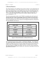
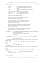
The currently supported binary commands and their definitions follow:
Command
Command Definition
128
send sensor data in binary format
129
send sensor data in IEEE 32 bit format
131
send angle data in binary format
132
send angle data in IEEE 32 bit format
The CXM544 response to these commands is of the following form:
<number of data bytes> <MX> <AX> <MY> <AY> <MZ> <AZ> <MT> <AT>
<0> <data check sum><end>
Refer to the next section of this manual (Heading Sensor Command Set) for a more detailed
discussion of the data format for binary transmissions.
5. Initial Setup of the System
In order to operate the CXM544, power must be applied to it and an interface with an external computer must be set up. Powering will depend upon whether the unit is using a +5V
supply or the internal regulators and powers from +7VDC to +12VDC. To ensure system
accuracy, the +5V powered system must be within ± 0.05V of +5V.
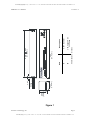
Connect the correct power lead to the selected supply voltage. (See Figure 2)
After powering, the system should consume about 71 ma of input current.
In order to set up a computer interface with the system, select the output protocol of the
CXM544. This can be either TTL or RS232. The TTL protocol is usually used in microprocessor to microprocessor communications. For this mode, the voltage levels for a 0 and 1 are
approximately ground and 5V. In the idle or marking state, the output level is +5V.
The RS232 protocol is used by using serial com ports. RS232 voltage levels for a 0 and a 1
are approximately -5V and +5V. In the idle or marking state, the -5V level is output.
About 1 second after power up, the CXM544 will send out a sign on message. This can be
observed with an oscilloscope as a series of transitions from +5 to 0V (TTL) or -5V to +5V
(RS232).
Since PC's use RS232 protocol, they can be directly connected to a CXM544 employing this
protocol. PC's use either a 25 pin or a 9 pin D connector to implement their serial ports. This
connector is always a bulkhead male connector on the P.C. chassis. The serial in, serial out
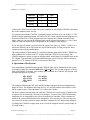
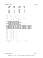
and ground connections for these connectors are as follows:
Crossbow Technology, Inc.
Page 7
SUNSTAR自动化 http://www.sensor-ic.com/ TEL: 0755-83376489 FAX:0755-83376182 E-MAIL:[email protected]