1
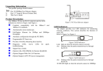
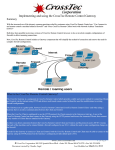
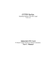
Introduction
The PCM-3662 is a 10/100 Mbps Ethernet interface module that attaches to the PC/104- plus connector on
your CPU card or PC/104-plus CPU module. The PCM-3662 provides 32-bit performance, PCI bus
capability, and full compliance with IEEE 802.3u 100Base-T specifications and IEEE 802.3x Full Duplex
Flow Control.
The module includes a built-in 10 pin box header and RJ-45 connector. Three diagnostic LEDs indicate the
operating status of the module and the network. You can define LEDs according to the application. The
PCM-3662 comes with drivers for a wide variety of networks and operating systems. An optional boot
ROM lets you boot a remote station automatically from a server, making hard or floppy disks unnecessary. Besides, PCM-3662 also provides Wake-ON-LAN function. This function can help you to remote
wake-up other PC with ATX power supply.
Features
PCM-3662 PC/104- plus Ethernet module
• Compliance with IEEE 802.3u Ethernet standard
• Support IEEE 802.3x Full Duplex Flow Control
• Support 10/100 Base-T Ethernet N-way Auto-negotiation operation
• Wake-On-LAN function and remote wake-up PC
• Support 32-bit general-purpose timer
• Remote boot ROM socket for diskless operation
• Support software drivers for most popular network environment such as Windows 95/98/NT/2000,
and Linux
PCM-3662 PC/104-plus Ethernet Module
PCM-3662 PC/104-plus Ethernet
Module
Block Diagram
Specification
PCM-3662 PC/104-plus Ethernet module
Hardware
• PC/104 form-factor: 64 x 8 mm
• Data bus: 32-bit
• Connectors: PC/104- plus stackthrough connector,RJ-45 connector for 10/100 BASE-T, 10-pin box
header
Software Driver support
• Windows 95/98/NT/2000 driver
• Novell sever driver
PC/104 and the PC/104 logo are trademarks of the PC/104 Consortium.
Part no. 2000366200 1st Edition Printed in Taiwan September 2000
• Windows for workgroups driver
• NDIS2 driver
• MacOS 8.x and 9.x driver
• Unixware 7.0 driver
• OS2 ODI driver
• Packet’s driver
• SCO 4.x/5.x Unix driver
• WinCE driver for x86 platform
• Novell ODI client driver
• Novell ODI driver for client32
• Linux driver
General
• Power: +5 V @250 mA
• Temperature: 0°C to 70°C (operating)
-15°C to 80°C (storage)
• Humidity:
10% to 90% (operating)
10% to 90% (storage)
Installation
Initial inspection
Your package should contain the following items. If they are missing, damaged or fail to meet specifications,
contact your dealer/sales representative immediately.
PCM-3662 PC/104-plus Ethernet Module
• This manual
• PCM-3662 board
• 3.5", 1.44 MB driver diskette
• 3.5", 1.44 MB utility diskette
• cable assembly for Wake-ON-LAN function
Locating components
2
PCM-3662 User's Manual
Software Configuration for PCM-3662
The PCM-3662 module is supplied with utility and driver disks. The driver disk contains various popular O.S.
drivers such as Windows 95/98/NT/2000, Linux etc. You can install it according to your needs. If you want to
update to the latest version of the drivers, you can refer to this web-site:
http://www.realtek.com.tw/cn/driver/8139-driver.htm
The utility disk contains the files necessary for setting up the Ethernet controller, directories and files on the disk
are as follows:
Rset8139.exe
This program enables you to view the current Ethernet configuration , reconfigure the Ethernet interface, and
execute useful diagnostic functions.
PG8139.exe
The PCM-3662 is initially set up at the factory using this program. When you receive your card , use
RSET8139.exe to configure it for the working environment. If by chance the EEPROM becomes corrupted, the
PG8139.exe program allows you to reconfigure the card.
8139B.cfg
When you run PG8139.exe, it will read the configuration parameters stored in this file.
Ethernet Interface Configuration
The PCM-3662 ‘s on-board Ethernet interface supports all major network operating systems. Each setting is easily
configured via the RSET8139.exe program included in the utility disk.
To execute the configuration, to view the current configuration, or to run diagnostics do the following:
1. Power the PCM-3662 on. Ensure that the RSET8139.EXE file is located in the working directory.
2. At the prompt type RSET8139.exe and press <Enter>. The Ethernet configuration program will then be
displayed.
3. A simple screen displays the available options for the Ethernet interface. Highlight the option which you wish
to change using the Up and Down keys. To change a selected item press <Enter>, and a window will appear
with the available options. Highlight your selection and press <Enter>. Each highlighted option has a helpful
message guide displayed at the bottom of the screen for additional information.
4. After you have made your selections and you are sure that this is the configuration you want, press <ESC>. A
prompt will appear asking if you want to save the configuration. Press Y if you want to save.
The Ethernet Setup Menu also offers three very useful diagnostic functions. These are:
1. Run EEPROM test.
2. Run Diagnostics on Board.
3. Run Diagnostics on Network
Each option has its own display screen which shows the format and result of any executed diagnostic tests.
Wake-ON-LAN function
PCM-3662 comes with Wake-ON-LAN(WOL) function and supports four WOL signals (active high, active low,
positive pulse, negative pulse). If you want to power on another PC remotely, refer to the following information.
Requirements:
1. Computers with ATX power supply.
2. Motherboard with Wake-ON-LAN function.
Steps:
1. Prepare two PCs with ATX power supplies and plug two PCM-3662s into said PCs. One is Master, the other is
Target.
2. Check the details of your motherboard. Find out which WOL signal the motherboard supports.
PCM-3662 User's Manual
3
3. Use the 3-pin Wake-ON-LAN cable to connect the Target PC and the connector of Wake-on-LAN in Target PC.
Notice the 3-pin connector’s pin-out and the cap. Connect at the input end of 5V-Vaux.
WOL connector's pin-out
5Vaux (red)
GND (black)
Wake-On-LAN (green)
Note: For lump 5V Vaux power supply, the cap connecting on 5Vaux pin must be large enough to improve the
compatibility between differing power supplies.
4. Turn on power of the Target PC. Execute RSET8139.exe in DOS environment and record the NODE ID of Target
PCM-3662. Then turn off power.
4
PCM-3662 User's Manual
5. Execute RSET8139.exe in Master PC
Run Diagnostics " Run Power Management Test " Master Machine " Magic Packet " Input Ethernet address
to match node ID of target machine (Target PCM-3662 Node ID)
6.Wake-up Target PC
Remote boot ROM
A boot ROM allows you to boot the workstation directly from the server, avoiding the need for local hard or floppy
disks. Install the boot ROM as shown below. If you want to change the size of the boot ROM, execute
RSET8139.exe and select boot ROM size.
PCM-3662 User's Manual
5
Hardware installation
The following shows a typical module stack with 2 PC/104-plus modules, 1 PC/104 16-bit module, and 1 PC/104
8-bit module. The maxinum configuration for the PCI bus of a PC/104-plus module is four plus the host board. If
standard PC/104 modules are used in the stack, they must be located at the top because they do not normally
include the PCI bus.
There are four PC/104-plus cards which are allowed in the PC/104-plus CPU system. If you want to install more
than one PC/104-plus module, you have to note that each module has different settings to avoid module conflicts.
For the PCM-3662, you can use JP3 to set up different signal settings to avoid conflicts with other PC/104-plus
modules. Please refer to the following table.
Slot 1
Slot 2
JP3
Slot 3
JP3
JP3
Slot
REQ*
GNT*
CLK
Slot 4
ID Address INTO*
JP3
INT1*
INT2*
INT3*
1
REQ0*
GNT0*
CLK0
AD20
INTA*
INTB*
INTC*
INTD*
2
REQ1*
GNT1*
CLK1
AD21
INTB*
INTC*
INTD*
INTA*
3
REQ2*
GNT2*
CLK2
AD22
INTC*
INTD*
INTA*
INTB*
4
REQ2*
GNT2*
CLK3
AD23
INTD*
INTA*
INTB*
INTC*
Because the PCM-3662 has to follow PCI 2.1 specifications, you can refer to those specifications for detailed
signal settings.
6
PCM-3662 User's Manual
PCM-3662 Installation
The following instructions tell how to install the PCM-3662 module on a CPU card. The process is similar with
PC/104-plus CPU modules. Make sure that you have properly attached a boot ROM if necessary.
Warning! TURN OFF your PC power supply whenever you install or remove the PCM-3662 or connect and
disconnect cables.
1.
2.
3.
4.
5.
6.
7.
8.
9.
Turn the PC’s power off. Turn off any peripheral devices such as printers and monitors.
Disconnect the power cord and any other cables from the back of the computer.
Remove the system unit cover (see the user’s guide for your chassis if necessary).
Remove the CPU card from the chassis (if necessary) to gain access to the card’s PC/104-plus connector.
Screw the brass spacer (included with the module) into the threaded hole on the CPU card. Do not tighten too
much, or the threads may be damaged.
Carefully align the connector pins of the PCM-3662 with the PC/104- plus connector. Slide the module into the
connector. The module pins may not slide all the way into the connector; do not push too hard or the module
may be damaged.
Select the Jumper 3.
Secure the module to the CPU card through the threaded hole in the CPU card using the screw included.
Reinstall the CPU card and replace the system unit cover. Reconnect the cables you removed in step 2. Turn
the power on. This completes the hardware installation. Install the software drivers as required.
Pin Assignment
10-pin Box Header (CN3)
Vdd
1
2
RCV+
3
4
5
6
XMT+
7
8
9
10
RCV-
XMT-
RJ-45 Pin Assignment
1
2
3
4
5
6
7
8
RJ-45 Connector
8
1
PCM-3662 User's Manual
7
8
PCM-3662 User's Manual