1
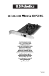
Black Box Tech Support: FREE! Live. 24/7.
Tech support the
way it should be.
Great tech support is just 20 seconds away at 724-746-5500 or blackbox.com.
About Black Box
Black Box Network Services is your source for more than 118,000 networking and infrastructure products. You’ll find everything.
from cabinets and racks and power and surge protection products to media converters and Ethernet switches all supported by
free, live 24/7 Tech support available in 20 seconds or less.
Copyright 2009. All rights reserved.
724-746-5500 | blackbox.com
SEPTEMBER 2009
LH1690C-SC
LH1690C-LC
Gigabit 1000Base-X PCI Express Fiber NIC
Fully complies with all IEEE 802.3z and
1000Base-SX/LX standards to provide
reliable gigabit ethernet connection.
Includes standard and low profile brackets.
Preboot Execution Environment (PXE), Remote Program Load (RPL)
Bootstrap Protocol (BOOTP), Multi-Boot Agent (MBA).
Customer
Support
Information
Gigabit 1000Base-X PCI Express Fiber NIC
Black Box and the Double Diamond logo are registered trademarks of BB Technologies, Inc.
Any other trademarks mentioned in this manual are acknowledged to be the property of the trademark owners.
We‘re here to help! If you have any questions about your application
or our products, contact Black Box Tech Support at 724-746-5500
or go to blackbox.com and click on “Talk to Black Box.”
You’ll be live with one of our technical experts in less than 20 seconds.
Page 2
724-746-5500 | blackbox.com
Table of Contents
1. Specifications ........................................................................................................................................................................................7
2. Overview ...............................................................................................................................................................................................8
2.1 Introduction .......................................................................................................................................................................................8
2.2 Features ............................................................................................................................................................................................8
2.3 What’s Included .................................................................................................................................................................................8
2.4 LED Description ................................................................................................................................................................................8
3. Hardware Installation ............................................................................................................................................................................9
4. Driver Installation .................................................................................................................................................................................12
4.1 Windows 98, ME, 2000, XP, Server 2003, VISTA (32-bit, 64-bit) ....................................................................................................12
4.2 Windows NT 3.51, 4.0 .....................................................................................................................................................................13
4.3 Linux ................................................................................................................................................................................................14
4.4 Netware ...........................................................................................................................................................................................15
5. Configuration .......................................................................................................................................................................................19
5.1 Network Remote Boot Configuration ...............................................................................................................................................19
5.2 Fiber Cable and Bandwidth .............................................................................................................................................................19
Page 3
Gigabit 1000Base-X PCI Express Fiber NIC
Federal Communications Commission and Industry Canada Radio Frequency Interference
Statements
Class B Digital Device. This equipment has been tested and found to comply with the limits for a Class B computing
device pur-suant to Part 15 of the FCC Rules. These limits are designed to provide reasonable protection against harmful
interference in a residential installation. However, there is no guarantee that interference will not occur in a particular
installation. This equipment generates, uses, and can radiate radio frequency energy, and, if not installed and used in
accordance with the instructions, may cause harmful interference to radio communications. If this equipment does cause
harmful interference to radio or telephone reception, which can be determined by turning the equipment off and on, the
user is encouraged to try to correct the interfer-ence by one of the following measures:
• Reorient or relocate the receiving antenna.
• Increase the separation between the equipment and receiver.
• Connect the equipment into an outlet on a circuit different from that to which the receiver is connected.
• Consult an experienced radio/TV technician for help.
Caution:
Changes or modifications not expressly approved by the party responsible for compliance could void the user’s authority
to operate the equipment.
To meet FCC requirements, shielded cables and power cords are required to connect this device to a personal computer
or other Class B certified device.
Circuit devices are sensitive to static electricity, which can damage their delicate electronics. Dry weather conditions or
walking across a carpeted floor may cause you to acquire a static electrical charge.
To protect your device, always:
• Touch the metal chassis of your computer to ground the static electrical charge before you pick up the circuit device.
• Pick up the device by holding it on the left and right edges only.
This digital apparatus does not exceed the Class B limits for radio noise emission from digital apparatus set out in the
Radio Interference Regulation of Industry Canada.
Le présent appareil numérique n’émet pas de bruits radioélectriques dépassant les limites applicables aux appareils
numériques de classe B prescrites dans le Règlement sur le brouillage radioélectrique publié par Industrie Canada.
Electronic Emission Notice
Federal Communications Commission (FCC) Statement
This equipment has been tested and found to comply with the limits for a class B computing device pursuant to Subpart J
of part 15 of FCC Rules, which are designed to provide reasonable protection against such interference when operated in
a commercial environment.
Page 4
724-746-5500 | blackbox.com
FCC Statements
Instrucciones de Seguridad
(Normas Oficiales Mexicanas Electrical Safety Statement)
1. Todas las instrucciones de seguridad y operación deberán ser leídas antes de que el aparato eléctrico sea operado.
2. Las instrucciones de seguridad y operación deberán ser guardadas para referencia futura.
3. Todas las advertencias en el aparato eléctrico y en sus instrucciones de operación deben ser respetadas.
4. Todas las instrucciones de operación y uso deben ser seguidas.
5. El aparato eléctrico no deberá ser usado cerca del agua—por ejemplo, cerca de la tina de baño, lavabo, sótano
mojado o cerca de una alberca, etc..
6. El aparato eléctrico debe ser usado únicamente con carritos o pedestales que sean recomendados por el fabricante.
7. El aparato eléctrico debe ser montado a la pared o al techo sólo como sea recomendado por el fabricante.
8. Servicio—El usuario no debe intentar dar servicio al equipo eléctrico más allá a lo descrito en las instrucciones de
operación. Todo otro servicio deberá ser referido a personal de servicio calificado.
9. El aparato eléctrico debe ser situado de tal manera que su posición no interfiera su uso. La colocación del aparato
eléctrico sobre una cama, sofá, alfombra o superficie similar puede bloquea la ventilación, no se debe colocar en
libreros o gabinetes que impidan el flujo de aire por los orificios de ventilación.
10. El equipo eléctrico deber ser situado fuera del alcance de fuentes de calor como radiadores, registros de calor,
estufas u otros aparatos (incluyendo amplificadores) que producen calor.
11. El aparato eléctrico deberá ser connectado a una fuente de poder sólo del tipo descrito en el instructivo de operación,
o como se indique en el aparato.
12. Precaución debe ser tomada de tal manera que la tierra fisica y la polarización del equipo no sea eliminada.
13. Los cables de la fuente de poder deben ser guiados de tal manera que no sean pisados ni pellizcados por objetos
colocados sobre o contra ellos, poniendo particular atención a los contactos y receptáculos donde salen del aparato.
14. El equipo eléctrico debe ser limpiado únicamente de acuerdo a las recomendaciones del fabricante.
15. En caso de existir, una antena externa deberá ser localizada lejos de las lineas de energia.
16. El cable de corriente deberá ser desconectado del cuando el equipo no sea usado por un largo periodo de tiempo.
17. Cuidado debe ser tomado de tal manera que objectos liquidos no sean derramados sobre la cubierta u orificios de
ventilación.
18. Servicio por personal calificado deberá ser provisto cuando:
A: El cable de poder o el contacto ha sido dañado; u
B: Objectos han caído o líquido ha sido derramado dentro del aparato; o
C: El aparato ha sido expuesto a la lluvia; o
D: El aparato parece no operar normalmente o muestra un cambio en su desempeño; o
E: El aparato ha sido tirado o su cubierta ha sido dañada.
Page 5
Gigabit 1000Base-X PCI Express Fiber NIC
European Community (CE) Electromagnetic Compatibility Directive
This equipment has been tested and found to comply with the protection requirements of European Emission Standard
EN55022/EN61000-3 and the Generic European Immunity Standard En55024.
EMC:
EN55022(2003)/CISPR-2( 2002): class B
IEC61000-4-2 (2001): 4K V CD, 8KV, AD
IEC61000-4-3( 2002): 3V/m
IEC61000-4-4(2001):1KV (power line), 0.5KV (signal line)
Page 6
724-746-5500 | blackbox.com
Specification
1. Specifications
Standards: IEEE 802.3z; Gigabit Ethernet 1000Base-SX/LX; IEEE 802.3x Full-Duplex Flow Control;IEEE 802.1Q VLAN
Connector: LH1690C-SC - 850nm SC multi-mode
LH1690C-LC - 850nm LC multi-mode
Fiber Optic Cable: 62.5/125, 50/125m multi-mode
Data Transfer Mode/Speed: Full duplex with flow control; 1000Mbps speed
Diagnostics LED on Bracket: LINK/ACT; FDX
Bus Slot: PCIe 1.1 Compliant
Power Requirement: Max. 5W, [email protected]
Ambient Temperature: 08 to 508C
Humidity: 5% to 90%
Emission: Complies with EMI Standard
FCC Class B
CE Mark
Software Support: Windows 98/ME
Windows 2000
Windows 2003
Windows XP
Windows NT 3.51, 4.0
Vista
Novell Netware 4.x,5.x,6.x
Linux driver
PXE & RPL Boot ROM
Page 7
Gigabit 1000Base-X PCI Express Fiber NIC
2. Overview
2.1 Introduction
LH1690C-SC and LH1690C-LC Gigabit Ethernet PCIe 1000SX/LX Fiber NICs are Gigabit Ethernet Boards that fully
complies with all IEEE 802.3z and 1000Base-SX/LX standards. Two LED indicators (LINK/ACT and FDX) on the bracket
will help to oversee the board link, activities and full-duplex status.
These two Gigabit Ethernet PCIe 1000SX/LX NICs support Preboot Execution Environment (PXE), Remote Program
Load (RPL), and Bootstrap Protocol (BOOTP). Multi-Boot Agent (MBA) is a software module that allows your networked
system to boot with the images provided by remote systems across the network.
2.2 Features
• High bandwidth 1000Mbps Network Speed
• Supports Full-Duplex Mode
• Supports IEEE 802.3x Full-Duplex Flow Control
• Supports PCI e x1 bus
• Compliant with PCIe Rev.1.1 Interface
• Supports Jumbo Frame
• Supports High Level VLAN Filtering Function
• Supports IP headers and TCP / UDP checksums offload
• Supports on-board screening of VLAN tagged Ethernet frames
2.3 What’s Included
Your package should include the following items. If anything is missing or damaged, please contact Black Box Technical
Support at 724-746-5500.
• Gigabit Ethernet PCIe 1000SX/LX Fiber NIC
• Driver and user’s manual CD
2.4 LED Description
LED
Color
Function
LINK/ACT
Green
Lit when cable connection is good and speed is at 1000Mbps.
Blinks when any traffic is present.
FDX
Green
Lit when full-duplex mode is active.
LINK/ACT
FDX
Figure 3-1. Diagnostic LEDs and Bracket
Page 8
724-746-5500 | blackbox.com
Hardware Installation
3. Hardware Installation
The following instructions apply to installing the Gigabit Ethernet adapter in most systems. Refer to the manuals that
were supplied with your system for details about performing these tasks on your particular system.
To install the Fiber NIC, perform the following procedure:
1. High voltage inside the system presents a safety hazard. Make sure the power is off before removing the cover.
Warning
Before installing the adapter, ensure the system power is OFF and unplugged from the power outlet, and that proper
electrical grounding procedures have been followed.
2. Remove the system cover and select any empty PCIe slot. See Figure 3-2. If you do not know how to identify a PCIe
slot, refer to your system documentation.
Figure 3-2. Removing the PC cover
Page 9
Gigabit 1000Base-X PCI Express Fiber NIC
3. Select an empty, non-shared PCIe slot and remove the faceplate. Keep the faceplate in a safe place. You may need it
for future use. See Figure3-3.
Note
If you cannot locate or know how to find an PCIe slot, refer to the
documentation that came with your system.
Figure 3-3. Removing the faceplate from PCI slot
4. Remove the fiber card from the shipping package and store the packaging material in a safe location.
Caution
Wear a grounding device and observe electrostatic discharge precautions when installing the fiber card in a system.
Failure to observe this caution could result in damage to the card.
5. Applying even pressure at both corners of the card, push the fiber card until it is firmly seated in the PCIe slot.
Make sure the card is securely seated. See Figure 3-4.
Figure 3-4. Place NIC to the PCIe slot
Page 10
724-746-5500 | blackbox.com
Hardware Installation
6. Replace the system's cover and secure it with the screws removed in Step 2.
Figure 3-5. Securing the NIC by screws
7. Disconnect any personal antistatic devices.
8. Power the system on.
Page 11
Gigabit 1000Base-X PCI Express Fiber NIC
4. Driver Installation
4.1 Windows 98, ME, 2000, XP, Server 2003, VISTA (32-bit, 64-bit)
1. Start your Windows system and log in. (You must have Administrator privileges to install the driver software.)
When you boot up the Windows system after installing the Fiber NIC, a series of windows opens.
NOTE
Before beginning this procedure, verify that the Windows system has been upgraded to the latest version with the latest
service pack applied.
2. In the Install Found New Hardware window, click No, not this time to copy the driver software from the CD-ROM. Click
Next.
Figure 4-1. Welcome to the Found New Hardware Wizard Window
3. The second Welcome to the Found New Hardware Wizard Window is shown in Figure 4-2. Insert the CD-ROM and
Click Install from a list or specific location (Advanced). Click Next.
Figure 4-2. Found New Hardware Wizard Window
Page 12
724-746-5500 | blackbox.com
Driver Installation
4. When prompted, insert the media to be searched into your CD-ROM drive, type the path to the driver, and select OK.
For example, where "e" is the designation of the CD-ROM drive on your system, enter:
e:\Win2K_XP_Srv2003\32
5. In the Driver Files Search Results window, verify that the correct path to the driver software is shown, then click Next.
The driver location for each Windows operation system is listed below.
Windows 98, ME: CD ROM Root:\Win98_ME
Windows 2000, XP, Server 2003 (32-bit): CD ROM Root:\Win2K_XP_Srv2003\32
Windows 2000, XP, Server 2003 (64-bit): CD ROM Root:\Win2K_XP_Srv2003\64
Windows VISTA (32-bit): CD ROM Root:\VISTA\32
Windows VISTA (64-bit): CD ROM Root:\VISTA\64
6. When the driver installation is completed, restart Windows if needed.
NOTE
On some machines, it is possible that some NICs fail to initialize. This might be caused by insufficient memory. Users
can try to decrease Tx or Rx buffer number to solve this problem.
The Flow Control setting "Hardware Default (Auto)" means the flow control ability depends on the auto-negotiation
result with the link partner. In other settings ("Enable Tx", "Enable Rx", "Enable Tx/Rx"), driver will set the Tx or Rx flow
control ability without auto-negotiation.
4.2 Windows NT 3.51, 4.0
Before starting with the installation process, make sure that the Fiber NIC is properly installed and configured.
1. Open "Control Panel" -> "Networks", and choose the "Add Adapter" button. The Add Noetwork Adapter dialog box
appears. Select "<other> Requires disk from manufacturer" in the list of Network Adapters, and then press <Enter>.
2. Insert the driver CD into your CD-ROM, and specify the path of the driver in the CD(i.e. D:\WINNT) if necessary.
3. Select the correct Adapter, and start to copy the driver files to your system.
4. After all the driver files have been copied to your system, a property dialog box appears in the screen. You can enable
the special properties if you want to.
5. When the driver installation is completed, restart your PC.
NOTE
The Flow Control setting "Hardware Default (Auto)" means the flow control ability depends on the auto-negotiation
result with the link partner. In other settings ("Enable Tx", "Enable Rx", "Enable Tx/Rx"), driver will set the Tx or Rx flow
control ability without auto-negotiation.
Page 13
Gigabit 1000Base-X PCI Express Fiber NIC
4.3 Linux
The instructions listed below are for linux driver installation. You must compile the source code to generate the module
velocityget.o (velocity.ko in 2.6.x kernel, please remember to replace velocityget.o with velocityget.ko in the following
sentences if you are using 2.6.x kernel) and use insmod command to insert it.
This driver supports linux kernel version 2.2.x, 2.4.x and 2.6.x now. For 2.6 kernel, it supported up to 2.6.18 in this version.
This driver supports x86 and AMD64 based linux system.
Please enter the following commands at the UNIX prompt. Remember, UNIX is case sensitive.
1. Create a temporary directory:
mkdir /temp
2. Change to the temporary directory:
cd /temp
3. Copy driver (.tgz file) from DOS disk, (mcopy below is one tool in mtools, if you didn't install mtools, you can type
'mount -t msdos /dev/fd0 /mnt' and use 'cp /mnt/velocityget.tgz /temp' command to copy the driver to the temporary
Directory):
mcopy a:velocityget.tgz
4. untar the archive file:
tar xzvf velocityget.tgz
cd src
5. Compile the driver source files and it will generate object file, and copy it to correct driver installation path (The
installation directory is different in different kernel versions. In 2.4.x/2.6.x kernel, the path is
/lib/modules/KERNEL_VERSION/kernel/drivers/net/, and in 2.2.x kernel, the path is
/lib/modules/KERNEL_VERSION/net/, the KERNEL_VERSION (see above) means the kernel version of your Linux
distribution. If you don't know your kernel version , please run 'uname -r' command in command line. The kernel
version will look like '2.2.16', '2.4.2-2smp' etc.) :
make install
6. Check configuration file (/etc/modules.conf or /etc/conf.modules or /etc/modprobe.conf, it depends on your Linux
distribution) for loading kernel modules. Make sure the first line below is appeared in the configuration file, where # is
the interface number (eg: alias eth0 velocityfet). If you need to set the driver options, below second line is an example
to set the NIC to 100Mbps fullduplex mode (remember to unmark the line if it is put in the configuration file).
alias eth# velocityget
7. Reboot now:
shutdown -r now
8. Install your driver module (If the driver module is in the wrong place, an error message will appear, and say that can't
find the driver module):
insmod velocityget.o
9. Use ifconfig command to assign the IP address, where # is network interface number:
ifconfig eth# <IP>
10. Check the interface works:
ping <remote_host_IP>
Page 14
724-746-5500 | blackbox.com
Driver Installation
4.4 Netware
4.4.1 Novell 32 Bit ODI Driver for Client32 in DOS
Before starting with the installation process, make sure that the Fiber NIC is properly installed and configured.
Install Driver While setting up your Client32:
While you are installing Client32 programs, please make the driver diskette of the Fiber NIC near you.
1. When the Installation program ask you to specify a lan driver, please select "OTHER DRIVERS" or "User Supplied
Driver" or "USER SPECIFIED 32 BIT DRIVER" to install driver from the CD or diskette that come with Fiber NIC.
2. Insert the driver diskette into your floppy drive, and specify the path of the driver in the diskette to copy the driver files
to your system.
3. A STARTNET.BAT file will be generated in the Client32 directory. (\NOVELL\CLIENT32 or other if you change the
default path)
4. When all the Clinet32 programs installation is completed, reboot your PC.
System with existing Netware client programs:
If there are Client32 programs installed in your system already, you can use the following procedures to setup your driver.
1. Add a Load driver command line to your STARTNET.BAT file in your Client32 directory. For example:
LOAD C:\NOVELL\CLIENT32\GETNWSC.LAN FRAME=Ethernet_802.2
The following is a sample of the STARTNET.BAT file:
SET NWLANGUAGE=ENGLISH
C:\NOVELL\CLIENT32\NIOS.EXE
LOAD C:\NOVELL\CLIENT32\LSLC32.NLM
LOAD C:\NOVELL\CLIENT32\CMSM.NLM
LOAD C:\NOVELL\CLIENT32\ETHERTSM.NLM
LOAD C:\NOVELL\CLIENT32\GETNWSC.LAN FRAME=Ethernet_802.2
LOAD C:\NOVELL\CLIENT32\GETNWSC.LAN FRAME=Ethernet_802.3
LOAD C:\NOVELL\CLIENT32\IPX.NLM
LOAD C:\NOVELL\CLIENT32\CLIENT32.NLM
2. Execute STARTNET.BAT to connect to Server.
NOTE
If want to use VID & TAG (HCHECKSUM for CHSM) keywords supported by management adapter, be aware of the string
length limitation in DOS prompt.
river will be unable to be loaded if using Client32 for DOS Installer v2.01. Please use Installer v2.71 and later for CHSM
Spec v1.11 driver.
4.4.2 Novell ODI 16-bit DOS Client Driver
Before starting with the installation process, make sure that the adapter is properly installed and configured.
Installation by using Netware ODI Client Install utility:
1. Enter the destination directory for the Netware client:
(The default directory is C:\NWCLIENT)
Page 15
Gigabit 1000Base-X PCI Express Fiber NIC
2. Install will modify your AUTOEXEC.BAT and CONFIG.SYS files.
Allow changes? (Y/N)
3. Do you want to install support for MS Window? (Y/N)
4. Select the driver for your network board:
• Scroll the list to choose OTHER DRIVERS.
• Press <Enter>, and the "Insert The Driver Disk" dialog box will be prompted. Type the path to the directory which
contain driver and information file.
(A:\NETWARE\DOSODI)
• Press <Enter> and select target ODI driver.
• Select optional settings.
• Press "F10" to save.
5. Press <Enter> to install.
System with existing Netware client programs:
If there are Netware client programs such as LSL.COM, IPXODI, and NETX.EXE in your system already, you can use the
following procedures to setup your system.
1. Copy the GETODI.COM file to the Netware client directory which contains NET.CFG, LSL.COM, IPXODI.COM, and
NETX.COM files.
2. Update the NET.CFG file. You can refer to the above sample.
3. Make sure to add LASTDRIVE=E in your CONFIG.SYS file if your want the first network drive to be F.
4. Enter the following commands to connect to your Novell server:
LSL
GETODI
IPXODI
NETX
F:
LOGIN <user_name>
If there are Netware client programs such as: LSL.COM, IPXODI, and VLM.EXE in your system already, you can use the
following procedures to setup your system.
1. Copy the GETODI.COM file to the Netware client directory which contains NET.CFG, LSL.COM, IPXODI.COM, and
NETX.COM files.
2. Update the NET.CFG file. You can refer to the above sample.
3. Make sure to add LASTDRIVE=Z in your CONFIG.SYS file.
4. Enter the following commands to connect to your Novell server:
LSL
GETODI
IPXODI
VLM
F:
LOGIN <user_name>
Page 16
724-746-5500 | blackbox.com
Driver Installation
4.4.3 Netware 4.0, 4.11, 4.12 Server Driver
Before starting with the installation process, make sure that the adapter is properly installed and configured.
Using Server Install utility:
1. On the server console, execute the INSTALL program:
LOAD INSTALL <Enter>
2. Choose "Driver Option/Configure network drivers/Select a driver".
3. Press the <Ins> key to install the driver which is not on the list.
4. Press <F3> to specify a different path and press <Enter>.
5. The GETNWSC.LAN should appear on the selection list. Press <Enter> to choose it.
6. You can "Select/Modify driver parameters and protocols", and then "Save parameters and load driver".
7. You can add the LOAD and BIND command lines to the AUTOEXEC.NCF file so that the LAN driver will be loaded
automatically while the server is starting up.
Loading Driver Manually:
1. On the server console, load the driver directly, for example:
LOAD A:\NETWARE\NWSERVER\GETNWSC FRAME=Ethernet_802.2
2. Bind with IPX:
BIND IPX GETNWSC
3. You can login the server from a workstation, and then copy GETNWSC.LAN to the directory SYS:\SYSTEM on server.
Add the LOAD and BIND command lines to AUTOEXEC.NCF file so that the lan driver will be loaded automatically
while the server starting up next time.
4.4.4 Netware 5.0, 5.1, 6.0, 6.5 Server Driver
Before starting with the installation process, make sure that the adapter is properly installed and configured.
Using Server Install utility:
1. Execute the NWconfig program, on the server console:
NWConfig <Enter>
2. Choose "Driver Option/Configure network drivers/Load an additional driver".
3. Press the <Ins> key to install the driver which is not on the list.
4. Press <F3> to specify a different path and press <Enter>.
5. The GETNWSC.LAN should appear on the selection list. Press <Enter> to choose it.
6. You can choose "Select/Modify driver parameters and protocols", and then choose "Save parameters and load driver"
to finish driver loading.
Loading Driver Manually:
1. On the server console, load the driver directly, for example:
LOAD A:\NETWARE\NWSERVER\GETNWSC FRAME=Ethernet_802.2
Page 17
Gigabit 1000Base-X PCI Express Fiber NIC
2. Bind with IPX:
BIND IPX GETNWSC
3. You can login the server from a workstation, and then copy GETNWSC.LAN to the directory SYS:\SYSTEM on server.
Add the LOAD and BIND command lines to AUTOEXEC.NCF file so that the lan driver will be loaded automatically
while the server starting up next time.
4.5 NDIS2
Before starting with the installation process, make sure that the adapter is properly installed and configured.
Installing driver procedure on DOS LAN Requester:
1. Install DOS Lan Requester to HardDisk with "NO Network Adapter Selected" option.
2. Copy GETND2.DOS from your Driver diskette to DOS LAN Services subdirectory, like C:\NET.
3. Under DOS LAN Requester subdirectory C:\NET, run INSTALL.
4. Move highlight to "The listed options are correct" item, then press ENTER.
5. Move highlight to "Network Card", then press ENTER.
6. Select "Change driver for network card." item, then press ENTER.
7. Select "Network card not shown in list below..", then press ENTER.
8. Insert the Gigabit Fiber Ethernet PCI-Express Bus Adapter diskette in floppy A, and specify the pathname A:\NDIS2,
then press ENTER.
9. PCI Ethernet NDIS2 driver is now installed on your computer, reboot your computer.
Page 18
724-746-5500 | blackbox.com
Configuration
5. Configuration
5.1 Network Remote Boot Configuration
1. Select Remote Boot Type
For entering “MBA Configuration Menu” to select Remote Boot Type (PXE, RPL), please press Shift-Tab within 3
seconds after power on your PC, otherwise, the system would go to Windows O.S.
2. Set Network Remote Boot
For setting network remote boot, please enter PC BIOS first, then select “Boot” tab, after that, choose “MBA” as the
priority first boot device.
3. Cancel Network Remote Boot
To cancel network remote boot, please change the “Boot” setting in PC BIOS from “MBA” to “Hard Drive” or other
Devices.
5.2 Fiber Cable and Bandwidth
Multi-mode (850 nm) Fiber Cable and Modal Bandwidth
Multi-mode 62.5/125mm
Modal Bandwidth
Distance
Modal Bandwidth
Distance
160 MHz-Km
220 meter
400 MHz-Km
500 meter
200 MHz-km
275 meter
500 MHz-Km
550 meter
Page 19