1
TS2068 Technical Manual
This is the second edition of the manual published by Time Designs
Magazine (now defunct). It is based on the original blue manual
released by Timex Computer Corp. shortly before it folded. Aside from
a page renumbering and some sections that were added in the second
edition, there is not a lot of difference between the two.
This doc was captured using Adobe Acrobat 3.0, the only software I could
find that did a half-decent job. There are still numerous errors where
Acrobat got confused, but I'm too lazy to fix them.
Alvin 05/10/98
aralbrec@concentric. net
TIMEX SINCLAIR 2068
PERSONAL COLOR COMPUTER
TECHNICAL REFERENCE MANUAL
Prepared by
V. C. Corcoran
and
M. H. Branigin
TIMEX COMPUTER CORPORATION
Waterbury CT 06720
o May 1984
S e c o n d Edition P r i n t i n g
Published Exclusively by:
TIME DESIGNS MAGAZINE CO.
COLTON, OREGON 97017
@ JANUARY 1986
PREFACE
This manual is dedicated to the many individuals associated
with the Timex Computer Corporation in the development and
production of the TS2068. Our special thanks to Nan Parsons
who prepared the TS2068 Schematic and other drawings used
in this manual.
While every effort has been made to make this document
information
complete and accurate, use of the technical
contained herein is at user's sole risk. The Timex Corp. or
its affiliates, and Time Designs Magazine Company assume no
responsibility or liability for the safety or performance
of any product manufactured relying on the technical data
loss,
damage, or
contained herein, or any liability,
expense sustained by reason of any claim that such products
infringe any patent or other industrial property right.
The Second Edition of this Technical Manual has been reedited by Tim Woods. Special thanks to Bob Orrfelt and Dave
Clifford for technical assistance.
If you would like to receive information on a magazine and
other publications for the Timex Sinclair 2068, direct your
inquiry to: Time Designs Magazine Company, 29722 Hult Rd.,
Colton,
, OR 97017.
T l m e x Slnclair 2068 Technical Manual (2nd Edition), C o p y r i g h t 1986 by the Tlme Designs
Magazine C o m p a n y . Reproduction of this document in whole or in p a r t b y a n y m e a n s w i t h o u t
e x p r e s s e d w r i t t e n permission f r o m T l m e Designs, Is prohibited by law.
This m a n u a l w a s p r i n t e d b y Toad’l Litho Printing and Composition, O r e g o n C i t y , O R 9 7 0 4 5 .
TARLE OF CONTENTS
1.0
INTRODUCTION
1.1
TS 2068 Overview 1
1.1.1
1.1.2
1.1.3
1
Hardware Overview
System Software Overview
Cartridge Software Overview
2.0
HARDWARE
2.1
Major Hardware Functions 7
2.1.1
2.1.2
2.1.3
2.1.4
2.1.5
2.1.6
2.1.7
2.1.8
2.1.9
2.1.10
2.1.11
2.1.12
2.1.13
GUIDE
7
AC Adapter
Voltage Regulation
Z80A CPU
ROM
32K RAM
Programmable Sound Generator
Joystick Port
Control Logic
Keyboard
16K Video Display RAM
Video Generation
Cassette I/O
Port Map
2.2
Schematic
2.3
Unit Absolute Ratings 53
2.4
Interfaces and Connectors 53
2.4.1
2.4.2
2.4.3
2.4.4
2.4.5
2.4.6
2.4.7
2.4.8
(see inside back cover and Appendix D)
System Bus Connector - Pl
Cartridge Connector - J4
Cassette I/O
Joystick
Composite Monitor Output
RF Output
Keyboard Interface Connector - J9
AC Adapter Power Plug
3.0
SYSTEM SOFTWARE GUIDE 65
3.1
Identifier 65
TABLE OF CONTENTS
(continued)
3.2
ROM Organization and Services 65
Home ROM
3.2.1
Fixed Entry Points
BASIC AROS Support
General
3.2.1.1
3.2.1.2
3.2.1.3
Extension ROM
3.2.2
Fixed Entry Points
General
Video Mode Change Service
Extension ROM Interface Routine
3.2.2.1
3.2.2.2
3.2.2.3
3.2.2.4
3.3
RAM Organization and Services 72
System
System
Machine
OS RAM
3.3.1
3.3.2
3.3.3
3.3.4
Variables
Configuration Table
Stack
Routines
RAM Interruption Handler
RAM Service Routines
Function Dispatcher
3.3.4.1
3.3.4.2
3.3.4.3
4.0
SYSTEM I/O GUIDE 91
4.1
I/O Channels 91
Keyboard
Video Screen
2040 Dot Matrix Printer
4.1.1
4.1.2
4.1.3
4.2
4.3
4.4
4.5
Cassette Tape 102
Joysticks 104
Software Generated Sound (BEEP)
Programmable Sound Chip (SOUND)
5.0
ADVANCED CONCEPTS
5.1
Cartridge
5.2
Advanced Video Modes
5.3
Other
106
Software/Hardware
125
117
106
105
105
TABLE OF CONTENTS
(continued)
6.0
KNOWN "BUGS" AND CORRECTIONS
6.1
6.2
6.3
LROS and Machine Code AROS
Machine Code AROS 126
BASIC AROS 127
Video Mode Change Service
129
OS General RAM Routines 134
:*9
6.6
126
126
127
APPENDICES
Appendix A - System ROM Maps/OS RAM Module 136
150
Appendix B - System Variables Definition File
158
Appendix C - Application Development Library
C-l
C-Z
c-3
c-4
c-5
64-Column Mode
80-Column Mode
40-Column Mode
Dual Screen Mode
Sprites
Appendix D - 288
D-l
D-2
D-3
TS2068 PCB Assembly Drawing
TS2068 Parts List
TS2068 Schematic Diagram
Appendix E - Expansion Buss Comparisons
295
Appendix F - Modifications for EPROMs
296
LIST OF FIGURES
FIGURE NO.
TITLE
1.1-1
1.1-2
1.1-3
1.1-4
TS 2068 Block Diagram
Memory Configuration
RAM Mapping
System Initialization Flowchart
2.1.3-1
2.1.3-2
2.1.3-3
2.1.3-4
2.1.3-5
2.1.4-1
2.1.6-1
2.1.6-2
2.1.6-3
2.1.6-4
2.1.6-5
2.1.6-6
2.1.6-7
2.1.6-8
2.1.6-9
2.1.6-10
2.1.6-11
2.1.7-1
2.1.8-1
2.1.8-2
2.1.9-1
2.1.10-l
2.1.11-1
CPU Timing
Op Code Fetch Timing
Memory Read/Write Timing
I/O Read/Write Timing
Interrupt Request/Ack.Cycle
Rework for EPROM's
PSG Register Block Diagram
Tone Period Registers
Noise Period Register
Mixer Control-I/O Enable Reg.
D/A Converter Signal Generation
Amplitude Control Registers
Variable Amplitude Control
Envelope Period Registers
Envelope Shape/Cycle Control Reg.
Envelope Generator Output
Envelope Generator Output Detail
Joystick Port Operation
Bank Selection Logic
Video RAM Address Generation
Keyboard Schematic
Video RAM Data Organization
Composite Video Signal
2.4.1-1
2.4.2-2
2.4.4-l
2.4.8-l
Pl Mating Connector Mechanical
Requirements
Pl Signal Layout
RGB Monitor Connection Schematic
J4 Mating Connector Mechanical
Requirements
J4 Signal Layout
Joystick Connector
AC Adapter Plug
3.2.2-l
3.2.2-2
Ext.ROM Interruption Fielder
Ext.ROM Interface Routine
4.1.1-1
4.1.1-2
Keyboard Mode Control
Keyboard Support Routines
Flowcharts
Standard Character Table Locations
Screen Row/Column Designations
Tape Header Formats
Joystick Data Format
2.4.1-2
2.4.1-3
2.4.2-l
4.1.2-1
4.1.2-2
4.2-l
4.3-l
LIST OF FIGURES
(continued)
FIGURE NO.
TITLE
5.1-1
5.1-2
5.1-3
5.1-4
EPROM Cartridge Board Schematic
Ctdg.Bd.Component Side Artwork
Ctdg.Bd.Solder Side Artwork
EPROM Cartridge Bd. Solder Mask
6.5-l
6.5-2
6.5-3
GET STATUS Corrections
PUT-WORD Corrections
BANK ENABLE and RESTORE -STATUS
Corrections
LIST OF TABLES
TABLE NO.
TITLE
2-l
Z80A Control Signals
2.1.6-1
2.1.6-2
PSG I/O Enable Truth Table
PSG I/O Port Truth Table
2.1.8-1
SCLD I/O Pin Function Definitions
2.1.13-1
I/O Port Map
2.4.1-1
Pl Signal Definitions
2.4.1-2
Pl Signal Electrical
Characteristics
2.4.2-l
J4 Signal Definitions
2.4.2-2
J4 Signal Electrical
Characteristics
2.4.4-l
Joystick Connector Signal
Assignment
3.2.2-l
Inputs to Video Mode Change
Service
3.3.4-l
OS RAM Service Routines
3.3.4-2
Function Dispatcher Services
1.0
INTRODUCTION
This manual provides detailed technical information on the Timex
Sinclair 2068 Personal Color Computer. In conjunction with the TS2068
User Manual, it is intended to assist the reader in understanding the
architecture, hardware and software features, programming techniques
and I/O techniques pertaining to the TS2068.
1.1
TS2068 Overview
1.1.1
Hardware Overview
Figure 1.1-1 is a block diagram of the TS2068 showing the
major
functional
logical
their
components
and
connections. These components are:
Control Logic - SCLD (Standard Cell Logic Device)
CPU
- Z80A Microprocessor
RA!!
- 48K Random Access Memory
ROM
- 24K System Read-Only Memory
(16K plus 8K Extension)
System Bus Connector
Cartridge Connector
Sound Generator/Speaker
Video Circuits
Cassette READ/WRITE
Joystick Connectors
The TS2068 Cartridge Connector provides for the plug-in
of cartridges containing programmed ROM's with up to 64K
of addressable memory.
The full 64K is not normally
due
to
need
for access to RAM for the
utilized (e.g.,
See
Section
5.1
for details.
machine stack).
Figure
1.1-2
standard
TS2068 memory
shows
the
configuration comprised of the Home Bank, the ROM
This
Extension Bank and the Dock (Cartridge) Bank.
memory is selectable as eight 8K 'chunks' with the Home
Bank being enabled by default, i.e., any chunk not
selected in the Extension or Dock Bank is automatically
enabled in the Home Bank.
Memory selection and I/O are controlled via the I/O
These topics are covered in detail in later
ports.
sections.
FIGURE 1.1-1
TS 2068 SYSTEM BLOCK DIAGRAM
r-l-l
16K
[” R A M
I
r KEYBOARD MATRIX
14.112 w
LHZ
A8-A15
1
T
FIGURE l.i-2
TS 2068 STANDARD MEMORY CONFIGURATION
QwNK
ADDRESS
FFFFH
RAM
ROY
RAM
6
ROM
RAY
5
AoeeN
48K
RAM
4
BooeN
3
6OMlN
2
4Mw
ROY
AAY
I
0
RAY
2oww
ROM
ROM
__..
r/
ROM
i 16K
ROM
HOWBANK
(BANK *255)
B
ROY
I
EXTENSJON BANK
(BANK -254)
2
CARTIttOWi
(DOCK)
UP TO 64K
‘Full 64K l ddr.s&ng *PM..
not normally utlllrad.
So. S4ctlon 5.1
1.1.2
System Software Overview
The TS2068 System Software resides in the Home ROM, the
Extension ROM, and dedicated RAM.
It supports the
following functions:
- System Initialization
- BASIC Interpreter (including BASIC cartridge support)
- BASIC I/O for Standard Peripherals
o
o
o
o
o
o
keyboard
video screen
2040 32-col. dot matrix printer
cassette tape
joysticks
software generated sound (BEEP)
o programmable sound chip (SOUND)
- Video Mode Change Service
- Interruption Servicing (Z80 Int. Mode 1)
- Bank Switching/Data Transfer Services
- Function Dispatcher (provides access to selected system
routines via a Service Code input)
In addition, portions of the Home Bank RAM are used for
the machine stack, the BASIC system variables, the
Printer Buffer and the Display Files. Figure 1.1-3 shows
the standard mapping of the Home Bank RAM and the mapping
necessary when the second display file is to be used with
The Video Mode
the BASIC interpreter still functional.
Change Service routine makes these memory modifications.
Note that there is no direct support of the second
display file via BASIC or in the system ROM I/O routines.
Figure 1.1-4 is a Flowchart of the System Initialization
process.
3
FIGURE 1.1-3
STANDARD MAPPING OF
HOME BANK RAM
P-RAYI
RAYTOF
F-RAY1
wo
OS
RAu-aEsmEwr cool!
MACMNE STACU
tzu:
STUEUB
SlUROf
WORKSP
E-LINE
VARS
SlNEMo
WOIUCSF
E-Llr(E
VA%4
PRtx
CKAMS
626&l
6owH
5CO.H
56oeH
OFTCoIl
RAMTOP
SluBoT
AllsRw
664ol-f
8F6caM
(MACHI)(E UmE VARIARLESI
(UACWE
OS R*LwIEw COtx
COOE VA-9
06PLArFLE2
yIcn*IE srAu
SVSTEY VA-S
-SrSlEY VARIABLES
-R BUFFER
PRINTER BUFFER
MSPUV~l
DfsFuV
4oa.H
A) 1 Dhpby Fk
4
F&E 1
CEES
ARSRUF
71uH
FIGURE 1.1-4
SYSTEM INITIALIZATION
POWER ON
SET MAX. ADDRESS
=(R*YToPl
SET -NEW- FLAG
SAVE (P-RAM),
~lJDCl.(PIP) 6
(RASP)
WC. PP.
L RASP
L
I
I
HITIALIZE SVSTEM
VARIABLES
(lJDG).tPIP)
6
To BASIC AROS
S u p p o r t Cd*
I
HITIALIZL
CHANS/STREAYS
I
la PRIN,,;, B U F F E R 1
I
COPY OS RAM
CODE TO CHUNK 3 t
5
J
’- Wil
1.1.3
Cartridge Software Overview
The TS2068 supports two basic types of Cartridge or
ROM-Oriented
Software
designated as
LROS (Language
ROM-Oriented Software) and AROS (Application ROM-Oriented
Software) which pluq into the cartridge connector. They
are identified via overhead bytes at Location 0 for an
LROS or 32768 (8000H) for an AROS.
The fundamental
difference is that an LROS contains 280 machine code in
memory chunk 0 and is in total control of the TS2068
hardware
including
RESTART implementation
the
and
Interruption Mode setting and handling, while an AROS is
dependent on the System ROM or an LROS for these
functions if needed. An AROS written in BASIC, which may
also include machine code accessed via the USR function,
is supported from the System ROM BASIC Interpreter and is
mapped beginning in memory chunk 4.
An AROS may also be
written entirely in Z80 machine code. An AROS written in
any other high-level language would require an LROS
supporting that language and would have to be integrated
with the LROS in a single cartridge.
See Sections 3.2.1.2, BASIC AROS Support and 5.1,
Cartridge Software/Hardware, for additional details.
6
2.0
HARDWARE GUIDE
2.1
Description of Major Hardware Functions
Figure 1.1-1 shows a simplified block diagram of the TS2068. The
following functional units are described in the following
sections:
SECTION
FUNCTIONAL UNIT
2.1.1
2.1.2
2.1.3
2.1.3.1
2.1.3.2
2.1.3.3
2.1.3.4
2.1.3.S
2.1.3.6
2.1.3.7
2.1.3.8
2.1.4
2.1.5
2.1.6
2.1.7
2.1.8
2.1.8.1
2.1.8.2
2.1.8.3
2.1.8.4
2.1.9
2.1.10
2.1.11
2.1.11.1
2.1.11.2
2.1.12
2.1.13
AC Adapter
Voltage Regulation
Z-80A CPU
Address Bus
Data Bus
Control Signals
OP Code Fetch
Memory READ/WRITE
I/O READ/WRITE
Maskable Interruption
Non-Maskable Interruption (NMI)
ROM
32K RAM
Sound Generator
Joystick Port
Control Logic
Bank Selection Logic
Z80 Clock Generator
Display File Access
Interruption Generation
Keyboard
16K Video Display RAM
Video Generation
Composite Video
RF Modulator
Cassette I/O
Port Map
2.1.1
AC Adapter
The AC Adapter transforms 117V AC (Nominal) to filtered
full-wave bridge
DC via a step down transformer,
rectifier, and filter capacitor to supply from 14 to 25
volts at 1 amp over the AC voltage variation range of 105
to 130 V AC. Transformer isolation exceeds 1500 volts.
AC 60Hz_ _
2.1.2 Voltage Regulation
Unregulated DC from the AC Adapter is supplied for
regulation through a bi-filar torroidal inductor which
reduces conducted line emanation for FCC compliance and
through the power-ON/OFF switch located on the left side
This switch voltage is supplied to the
of the TS2068.
System Bus Connector (see Section 2.4) and for regulation
to the +12 V regulator and the +5 V regulator.
Characteristics are as follows:
SUPPLY
5V
12v
VOLTAGE RANGE
CURRENT RANGE
4.75 - 5.25V
11.5 - 12.5V
200ma - 1.0 A
20ma - lOOma
> +20v
14 to 25v
DC
)
+5v
REGULATOR
b +12v
GND ,
The 12V regulator is a 78L12 series , regulator while the
5V regulator is a switching supply utilizing the 78S40
circuit.
2.1.3 Z-80A CPU
The Z-80A CPU of the TS2068 operates at a clock frequency
of 3.53 MHz. Primary features of this CPU are:
158 instructions
Dual register set
Two index registers
On-chip refresh logic
The Z-80 CPU executes instructions by proceeding through
a sequence of operations that include:
a)
b)
c)
d)
instruction Op code fetching
READ or WRITE memory
READ or WRITE I/O
Acknowledge an interruption
The basic clock period is referred to as a T time or
state and three or more T states make up a machine
In the TS2068, each T-time is approximately 283
cycle.
Figure 2.1.3-1
(2.83 X 10⁻⁷ seconds).
nanoseconds
illustrates the basic timing.
FIGURE 2.1.3-1
BASIC CPU TIMING EXAMPLE
f 1
12
‘3
14
‘1
12
13
11
2.1.3.1
Address Bus
Output from the Z-80 are 16-bits of address
information, A0 - A15, which are high-active
tri-state signals and address for memory data
and I/O device exchanges.
2.1.3.2
Data Bus
These input/output signals from the Z-80, DO constitute an
8-bit
bi-directional,
D7,
high-active, tri-state data bus used for data
exchanges with memory and I/O devices.
2.1.3.3
Control Bus
Associated with the Z-80 are 13 control lines
which are provided by or used by the Z-80 to
control system operation.
These signals are
detailed in Table 2-l.
2.1.3.4
Op Code Fetch
The timing during an Ml cycle (OP Code Fetch)
is shown in Figure 2.1.3-2. At the beginning
of the Ml cycle the PC (Program Counter) is
placed onto the address bus, then one-half
clock time later the /MREQ signal goes active
indicating that the memory address is stable.
The
signal is activated to indicate that
memory read data should be gated onto the data
bus.
At the rising clock edge during the T3
state, the CPU samples the data on the data bus
and deactivates the /RD and /MREQ signals.
During the T3 and T4 states, the CPU decodes
and executes the fetched instruction and the
CPU places on the lower 7 bits of the address
bus a memory refresh address and activates the
/RFSH signal indicating a refresh read is to
begin when /MREQ is activated.
2.1.3.5
Memory READ/WRITE
Memory read or write cycles other than Op Code
Fetches are 3 clock periods long with the /
M
R
E
Q
and R[T signals used as in the fetch cycle.
During a write cycle them signal is activated
when the write data is stable on the data bus.
The address and data bus contents remain stable
for one-half T state after the m signal goes
active. Figure 2.1.3-3 illustrates.
10
FIGURE 2.1.3-2
INSTRUCTION OP CODE FETCH
WI)T
iii
DO - 07
Rii
FIGURE 2.1.3-3
MEMORY READ OR WRITE CYCLES
-
wlmwv
‘1
Q
A0 = Al5
i
I
r’
‘\
MEMOAV ADDR
I
11
I
*
Mmor* WlllC Cvclr
‘1
‘3
72
t
*
R*rd C*d*
‘3
72
47
(7
i-
MEMOR V ADDR
I
I
2.1.3.6 I/O READ/WRITE
During I/O operations RJl?Q and Kb or l?R are
activated on the leading edge of the T2 clock
and a single Wait state is automatically
inserted as illustrated in Figure 2.1.3-4. The
l?lJ and m signals are used to enable data from
the addressed port onto the data bus and to, on
the rising edge of AR, clock data to the I/O
port, respectively.
Note that external I/O may
stretch the activation period of the $fX'i' line
to extend the I/O cycles.
FIGURE 2.1.3-4
INPUT OR OUTPUT CYCLES
A 0 -Al
WR
OATA
WflU
>
OW -
l Inserted bv 280 CPU
12
Cvclr
2.1.3.7 Maskable Interruption
When enabled by software, when -BITsRb is not
active and when RisT is active at the rising
edge of the last clock of any instruction, a
maskable
interruption
during
the
occurs
subsequent Ml cycle, as illustrated in Figure
2.1.3-5.
FIGURE 2.1.3-5
INTERRUPT REQUEST / ACKNOWLEDGE CYCLE
DATA BUS -----_
-_~-__-~_----l--_--l_____I_____
WAIT
_
_,----_.----_.-----m----m--_-
G
Mode
In Interruption Mode 0, the interrupting I/O
device places any instruction on the data bus
during the Imactivation and the CPU executes
The RESTART instruction is
that instruction.
m will
commonly used for this purpose.
automatically set Interruption Mode 0.
In Interruption Mode 1, the CPU executes a
RESTART to Location 0038H.
This is the mode
normally used by the TS 2068 software.
In Interruption Mode 2, the CPU concatenates
the 8-bit argument, which must be a E-byte
boundary address, with the 8-bit I Register
contents to form a 16-bit pointer to a memory
table entry containing the 16-bit service
routine address
the first byte in the table
13
0
being the low order portion of the address.
Once the interrupting device supplies the lower
portion of the pointer (for concatenation), the
CPU automatically pushes the PC onto the stack,
obtains the starting address from the table,
and does a jump to that address.
19 clock
periods are required to complete this sequence.
2.1.3.8 Non-Maskable Interruption (NMI)
A pulse on the m input to the Z80 sets the
internal latch which is tested by the CPU at
the end of each instruction.
The NMI has
priority over the maskable interruption and its
reponse is
identical to
maskable
the
interruption (Mode 1) except that the call
location is 0066H instead of 0038H.
NOTES: 1.
2.
14
The NMI is not
2068.
used
by
the
TS
Comments in
the ROM listing
claiming to "mask the NMI” via
the
DI
instruction
are
incorrect.
The DI instruction
masks
only
maskable
the
interruption.
TABLE 2-1
Z-80 CONTROL SIGNALS
ACRONYM
SYSTEM CONTROL
DEFINITION
Machine Cycle 1 - Output, active low.
This
siqnal indicates that the current machine cycle
is-the OP code fetch cycle.
During execution
of instructions having a 2-byte OP code, this
signal is
enerated as each OP code byte is
fetched. 19e is also used with Imto indicate
an interrupt acknowledge cycle.
MR~Q
Memory Request - Tri-state output, active low.
This signal indicates that the Address Bus
holds a valid address for a memory read or
write operation.
IORQ
I/O Request - Tri-state output, active low.
This signal indicates that the lower half of
the Address Bus holds a valid I/O address for
This signal is
an I/O read or write operation.
with
also
used
with li!l- in
connection
acknowledging an interruption, indicating that
an interrupt response vector can be placed on
the data bus.
I/O operations never occur
during Ml-time.
Memory Read - Tri-state output, active low.
Tm indicates that the CPU wants to
The
read data from memory or an I/O device.
addressed memory or device should use this
signal to gate the requested data onto the CPU
data bus.
m-
Memory Write - Tri-state output, active low.
This signal indicates that the CPU data bus
holds valid data to be stored in the addressed
memory or I/O device.
RI-SH
This signal
Refresh - output, active low.
indicates that the lower 7 bits of the Address
Bus contain a refresh address for dynamic
memories and the current.7 signal should be
used to do a refresh read to all dynamic
memories.
A7 is a logic zero and the upper 8
bits of the Address Bus contain the contents of
the I Register.
15
TABLE 2-1
Z80 CONTROL SIGNALS
(continued)
ACRONYM
CPU CONTROL
'DEFINITION
Halt State - Output, active low. This signal
indicates that the CPU has executed a HALT
CPU operations are suspended
instruction.
until a Non-Maskable or a Maskable Interruption
(with the mask enabled) occurs. While halted,
the CPU executes NOP's to maintain memory
refresh.
WAIT
low.
Wait Input,
active
This signal
indScates to the CPU that the addressed memory
or I/O device is not ready for a data
The CPU will continue to enter wait
transfer.
states as long as this signal is active. This
allows for synchronization of the CPU to
external devices of varying speeds.
This
Interrupt Request - Input, active low.
signal is generated by external devices and is
honored at the end of the current instruction
if the interrupt is not masked by the software
and if the m signal is not active. When
interruption, an
CPU
accepts
the
the
acknowledge signal is sent out at the beginning
of the next instruction cycle Cm at Ml
There are three interruption modes
time).
selectable by the software.
Non-Maskable Interruption - Input, negative
This signal has a higher
edge triggered.
priority than mand is always recognized at
the end of the current instruction (cannot be
The CPU is forced to restart to
masked).
location 0066H with the program counter saved
in the external stack. NOTE: The NMI is not
used in the TS2068 ROM software design.
16
TABLE 2-1
Z80 CONTROL SIGNALS
(continued)
DEFINITION
ACRONYM
CPU BUS CONTROL
RESET
This signal forces
Reset - Input, active low.
-program counter to zero and initializes the
Address and data buses go to their high
CPU.
impedance state and control output signals to
their inactive
No refresh occurs.
state.
Initialization includes: Disable the interrupt
enable flip-flop and set Register I, Register R
and the Interrupt Mode all to Zero.
m
Bus Request - Input, active low.
This signal
is used to request the CPU address bus, data
bus and tri-state output control signals to qo
to a high impedance state permitting other
The CPU sets
devices to control these buses.
these buses to a high impedance state at the
termination of the current Machine cycle.
BUSAK
This
Bus Acknowledge - Output, active low.
signal is used to indicate to the requesting
device that the CPU has set its address, data
and control bus signals to a high impedance
state in response to BUSR5R
Figure 2.1.4-1
REWORK TO REPLACE ROM's with EPROM's
17
2.1.4 ROM
The system includes both a 16K byte ROM and an 8K byte
ROM mapped into the address space as shown below.
3FFFh
(u16)
16K
ROM
1FFFh
OOOOh ,
OOOOh
4
HOME BANK
EXPANSION BANK
Section 2.1.8.1 describes the selection of the Home Bank
and Expansion Bank via the control logic.
The devices involved are a 23128 and a 2364 for the 16K
byte (128K-bit) and the 8K byte (64K-bit)
ROM's
Direct replacement of these devices with
respectively.
27128 and 2764 EPROM's is not possible since pins 1 and
27 must be maintained in the high state for those devices
(see schematic in Section 2.2). To replace U16 and U20
with 27128 and 2764 EPROM's requires the rework shown in
Figure 2.1.4-1.
(1) Cut input to pin 27 on each chip.
(2) Wire +5V to pins 1 and 27 on each chip to pull high.
If U20 is to be a 27128, then replace the RD input to pin
26 with address Al3 from pin 26 on U16.
2.1.5 32K RAM (Address 8000-FFFFH)
The upper 32K of RAM is composed of four 200ns 4416's
(16K x 4 dynamic RAMs).
18
2.1.6 Sound Generator
The Programmable Sound Generator (GI 8912) is accessed via Ports
OF5H (Address) and OF6H (Data). The basic registers in the PSG
which produce the programmed sounds include:
Produce the basic square wave tone frequencies
Tone Generators:
for each channel (A, B, C).
Produces a frequency modulated pseudo-random
Noise Generator:
pulse width square wave output.
Mixers: Combine the outputs of the Tone Generators and the Noise
Generator. One for each channel (A, B, C).
Provides the D/A Converters with either a
Amplitude Control:
The fixed amplitude is
fixed or variable amplitude pattern.
the
variable
amplitude
is accomplished
under direct CPU control;
by using the output of the Envelope Generator.
Produces an envelope pattern which can be
Envelope Generator:
used to amplitude modulate the output of each Mixer.
The three D/A Converters each produce up to a
D/A Converters:
16-level output signal as determined by the Amplitude Control.
An additional register is shown in the PSG Block Diagram (Figure
2.1.6-l) which has nothing directly to do with the production of
Data to/from the CPU may be
sound -- this is the I/O Port (A).
read/written to/from the 8-bit I/O Port without affecting any
The TS 2068 uses the I/O Port to
other function of the PSG.
access the joysticks.
2.1.6.1 Tone Generator Control (Registers RO-R5)
The frequency of each square wave generated by the three Tone
Generators (one each for Channels A, B, and C) is obtained in the
PSG by first counting down the input clock by 16, then by further
counting down the result by the programed 12-bit Tone Period
Each 12-bit value is obtained in the PSG by combining the
value.
contents of the relative Coarse and Fine Tune registers, as
illustrated by Figure 2.1.6-2.
Note that the 12-bit value programed in the combined Coarse and
Fine Tune registers is a period value -- the higher the value in
the registers, the lower the resultant tone frequency.
Note also that due to the design technique used in the Tone
Period countdown, the lowest period value is 000000000001 (divide
by 1) and the highest period value is 111111111111 (divide by
4095).
19
FIGURE 2.1.6-l
PSG REGISTER BLOCK DIAGRAM
R7
R8
R9
R10
Rll
R12
R7
R8
R9
RA
RB
RC
R13 RD
R14 RE
A
BI
C
BI A
Enable
IOB 1 IOA 1 C
X7
M 1 L3 L2 Ll i L
RlO Ch.A Amplitude /f////////f//////
L2 ,Ll 1 _ L
Rll Ch.B Amplitude ,///////////////// M 1 L3
Rl2 Ch.C Amplitude I//////////////// M / L3 L2 1 Ll 1 LO
8 Bit Fine Tune E
Envelope
Rl3
I
8
Bit Coarse Tune E
Period
R14
1
1 Envelope
I
I
I
vlllllll~l~~~~~~~~~~///I
R15 Shape/Cycle
~//////////r////////////iCONT.IATT. IALT. IHOLD
I/O Port A
8 Bit Parallel I/O on Port A
Rl6 Data Store I
4
FIGURE 2.1.6-2
12-BIT TONE PERIOD (TP) TO TONE GENERATOR
COARSE TUNE
REGISTER
Rl
R3
R5
FINE TUNE
REGISTER
CHANNEL
RO
R2
R4
A
!
iB7 B6 B5 B4 B3 B2 Bl BO 1
B7 B6 B5 B41B3 B2 Bl BOI
I
\
TPll TPlO TP9 TP8 1 TP7 TP6 TP5 TP4 TP3 TP2 TPl TPo(
20
2.1.6.1 (continued)
The equations describing the relationship between the desired output tone
frequency and the input clock frequency and Tone Period value are:
(a) fT = fCLOCK
16TP
10
Where:
(b) TP
fT
=
= 256CT
10
+ FT
10
Desired tone frequency
fCLOCK =
Input clock frequency
TP
=
Decimal equivalent of the Tone Period
bits TPll to TPO
CT
10
=
Decimal equivalent of the Coarse Tune
register bits B3 to BO (TPll to TP8)
FT
10
=
Decimal equivalent of the Fine Tune
register bits B7 to BO (TP7 to TPO)
10
From the above equations, it can be seen that the tone frequency can range
from a low of:
fCLOCK/65520 (wherein TP
10
= 4095
10
)
to a high of:
fCLOCK/16 (wherein TP
10
= 1).
The TS 2068 uses a 1.76475 MHZ input clock, so it can produce a range of 26.9
Hz to 110 kHz.
21
2.1.6.1 (continued)
To calculate the values for the contents of the Tone Period Coarse and Fine
Tune registers, given the input clock and the desired output tone frequencies,
we simply rearrange the above equations, yielding:
(a)
TP
= fCLOCK
10 76
Example 1:
TP
(b)
fT = 1 kHZ
= 1.76475x 10
10
3
16(1x10 )
CT
+
10
FT
=
TP
fCLOCK
K = 1.76475 MHz
6
=
110.3
Substituting this result into equation (b):
CT
+FT
10
=
110.3
resulting in:
CT
10
FT
10
= 0000 (B3-BO)
2
= 0
= 110
= 01101110 (B7-BO)
2
10
Example 2:
fT = 100 Hz
6
TP
= 1.76475~10
10 2
16(1x10 )
fCLOCK
K = 1.76475 MHz
=
1103
Substituting this result into equation (b):
CT
10
+ FT
= 1103
= 4 + 79/256
resulting in:
CT
FT
10
10
= 4
10
= 79
10
=
0100 (B3-BO)
2
= 01001111 (B7-BO)
2
22
2.1.6.2 Noise Generator Control (Register R6)
The frequency of the noise source is obtained in the PSG by first
counting down the input clock by 16, then by further counting
down the result by the programmed 5-bit Noise Period value. This
5-bit value consists of the lower 5 bits (B4-BO) of Register R6
as illustrated by Figure 2.1.6-3.
FIGURE 2.1.6-3
PERIOD REGISTER R6
NOISE
1
B/
B6
BS 1
NOT USED
B4
B3
B2
Bl
BO
1
PERIOD (NP)
TO NOISE GENERATOR
5-BIT NOISE
Note that the 5-bit value in R6 is a period value -- the higher
the value in the register, the lower the resultant noise
Note also that, as with the Tone Period, the lowest
frequency.
period value is 00001 (divide by 1); the highest period vam
11111 (divide by 31 1.
10
The noise frequency equation is:
Where:
fN
=
fCLOCK
16 NP
10
= Desired noise frequency
fN
fCLOCK = Input clock frequency
NP
= Decimal equivalent of the
10
Noise Period register bits
B4-B0.
From the above equation it can be seen that the noise frequency
can range from a low of fCLOCK/496 (wherein NP =31 )
10 10
to a high of fCLOCK/16 (wherein NP = 1). Using a 1.76475 MHz
10
clock, for example, would produce a range of noise frequencies
from 3.6 kHz to 110.3 kHz.
To calculate the value for the contents of the Noise Period
register, given the input clock and the desired output noise
frequencies, we simply rearrange the above equation, yielding:
NP
10
=
fCLOCK/l6fN
23
2.1.6.3 Mixer Control I/O Enable (Register R7)
Register 7 is a multi-function Enable register which controls the
three Noise/Tone Mixers and the two general purpose I/O ports.
The Mixers, as previously described, combine the noise and tone
frequencies for each of the three channels. The determination of
combining neither/either/both noise and tone frequencies on each
channel is made by the state of bits B5 thru BO of R7.
The direction (input or output) of the two general purpose I/O
ports (IOA and IOB) is determined by the state of bits B7 and B6
of R7. Note that in the TS 2068 there is no second I/O Port B.
These functions are illustrated by Figure 2.1.6-4 and Tables
2.1.6-l and 2.1.6-2 below.
FIGURE 2.1.6-4
MIXER CONTROL - I/O ENABLE REGISTER R7
1
87
6
1
1
BS
1
84
J
83
B2
/
Bl
1
BO 1
1
\
I
TABLE 2.1.6-1
I/O ENABLE TRUTH TABLE
85 84 B3
0 0 0
0
01
0 1 0
0 1 1
10
0
1 0 1
1 1 0
1 1 1
TONE ENABLE TRm TABLt
Tone tnabled
R/ BITS
on Channel
B2 Bl BO
LE TRUTH TABLt
Noise tnabled
on Channel
C
C
-
A
A
:B
A
B
A
_
_
;
B
B
0
0
0
0
01
0 1 0
0 1 1
10
0
1 0 1
1 1 0
1 1 1
-
24
C
C
C
c
!
B
B
-
A
A
A
A
TABLE 2.1.6-2
I/O PORT TRUTH TABLE
I R’ ET”
I
I/O Port Status
IOA
0
1
Input
output
NOTE
Turning a
Disabling noise and tone does not turn off a channel.
channel off can only be accomplished by writing all zeroes into the
corresponding Amplitude Control register, R8, R9 or RlO (refer to
Paragraph 2.1.6.4).
2.1.6.4 Amplitude Control (Registers R8, R9, RlO)
The amplitudes of the signals generated by each of the three D/A
Converters (one each for Channels A, B, and C) is determined by
the contents of the lower 5 bits (B4-BO) of Registers R8, R9 and
RlO as illustrated by Figure 2.1.6-5.
FIGURE 2.1.6-5
D/A CONVERTER SIGNAL GENERATION
AMPLITUDE CONTROL
REGISTER #
CHANNEL
A
R8
R9
RlO
:
I B’ B6 BS 1 B4 1 B3 B2 B1 B” L2 Ll
USED
f
Amplitude
'Mode'
LO
4-Bit Fixed
Amplitude Level
25
2.1.6.4 (continued)
The amplitude 'mode' (Bit M) selects either fixed level amplitude (M=O)
or variable level amplitude (M=l). It follows then that Bits L3-LO
defining the value of a 'fixed' level amplitude, are only active when
M=O. When fixed level amplitude is selected, it is 'fixed' only in the
sense that the amplitude level is under the direct control of the
system processor (via bits L3-LO).
Varying the amplitude when in this
'fixed'
amplitude
mode
requires
in each
instance
the direct
intervention of the system processor via an address latch/write data
sequence to modify the L3-LO data.
When M=l (select 'variable' level amplitudes), the amplitude of each
channel is determined by the envelope pattern as defined by the
Envelope Generator's 4-bit output E3-EO (refer to Paragraph 2.1.6.5).
The amplitude 'mode' (Bit M) can be thought of as an 'envelope enable'
bit, i.e. when M=O the envelope is not used, and when M=l the envelope
is enabled.
Figure 2.1.6-6 illustrates all combination of the 5-bit Amplitude
Control.
FIGURE 2.1.6-6
AMPLITUDE CONTROL REGISTERS
AMPLITUDE CONTROL
REGISTER #
R8
R9
RlO
CHANNEL
A
B
C
E
Amplitude Control
\
L3 :2 :1 Lb
output
0
0
0
0
0
o
0
0
0
0
“0
0
0
0
.
.
.
.
.
.
.
.
.
.
.
.
.
.
.
.
i
i
i
i
l
*.*
1xXxX
(X=Don't Care1
I...
ii-ii
E3 E2 El EO
The amplitude
is fixed at 1 of
16 levels as
determined by
L3-LO.
The amplitude is
variable at 16
levels as determined by the
output of the
Envelope Gen.
*The all zeros code is used to turn a channel "off".
26
2.1.6.4 (continued)
Figure 2.1.6-7 graphically illustrates a selection of variable level
(envelope-controlled) amplitude where the 16 levels directly reflect
the output of the Envelope Generator.
A fixed level amplitude would
correspond to only one of the levels shown, with the level directly
determined by the decimal equivalent of Bits L3-LO.
FIGURE 2.1.6-7
VARIABLE AMPLITUDE CONTROL (M=l)
15
AEPRESENTATI~N of
VALUES OF THE
AMPLITUOE CONTROL OUTPUT
Gtwwc
I.
THE DECIMAL
13
12
CHANNEL AT
MAXIMUM
AMPLITUDE
$1
IO
9
\ 0
2.1.6.5 Envelope Generator Control (Registers Rll, R12, R13)
To accomplish the generation of fairly complex envelope patterns,
two independent methods of control are provided in the PSG;
first, it is possible to vary the frequency of the envelope using
registers Rll and R12; and second, the relative shape and cycle
pattern of the envelope can be varied using register R13.
The
following paragraphs explain the details of the envelope control
functions, describing first the envelope period control and then
the envelope shape/cycle control.
2.1.6.5.1 Envelope Period Control (Registers Rll, R12)
The frequency of the envelope is obtained in the PSG by first
counting down the input clock by 256, then by further counting
down the result by the programed 16-bit Envelope Period value.
This 16-bit value is obtained in the PSG by combining the
contents of the Envelope Coarse and Fine Tune registers, as
illustrated by Figure 2.1.6-8.
27
FIGURE 2.1.6-8
16-BIT ENVELOPE PERIOD (EP) TO
ENVELOPE GENERATOR
ENVELOPE
COARSE TUNE
REGISTER R12
ENVELOPE
FINE TUNE
REGISTER Rll
Note that the 16-bit value programmed in the combined Coarse and
Fine Tune registers is a period value - the higher the value in
the registers, the lower the resultant envelope frequency.
Note also that, as with the Tone Period, the lowest period value
is 000000000000001 (divide by 1); the highest p-value is
1111111111111111 (divide by 65,535 ).
2
10
The envelope frequency equations are:
(a)
Where:
fEE = fCLOCK
256 EP
(b)
10
EP
10
= 256 CT + FT
10
10
Desired envelope frequency
Input clock frequency
Decimal equivalent of the Envelope
Period bits EP15-EPO
Decimal equivalent of the Coarse
Tune register bits 87-60 (EP15-EP8)
Decimal equivalent of the Fine
Tune register bits B7-BO (EP7-EPO)
::LOCKl
EP
=
10
CT
=
10
FT
=
10
From the above equation it can be seen that the envelope frequency can
range from a low of fCLOCK/16,766,960 ,. (wherein EP = 65,535 )
10
10
to a high of fCLOCK/256 (wherein EP =l). Using a 1.76475 MHz clock,
10
10
for example, would produce a range of envelope frequencies from 0.105
Hz to 6893.6 Hz.
28
To calculate the values for the contents of the Envelope Period Coarse
and Fine Tune registers, given the input clock and the desired envelope
frequencies, we rearrange the above equations, yielding:
(a)
EP
= fCLOCK
10 256fE
(b) CT + FT
EP
10
&=+
Example:
= 0.5 Hz
fE
fCLOCK = 1.76475 MHz
EP
= 1.76475 x 10
10
256(0 . 5)
6
=
13787
Substituting this result into equation (b):
CT
CT
FT
10
10
10
+ FT
= 13787
1 0
2 5 6
256
= 53
= 00110101
= 219 = 11011011
=
2
2
53
+ 219
256
(B7-BO)
(87-80)
2.1.6.5.2 Envelope Shape/Cycle Control (Register R13)
The Envelope Generator further counts down the envelope frequency
by 16, producing a 16-state per cycle envelope pattern as defined
The particular shape and
by its 4-bit counter output, E3-EO.
cycle pattern of any desired envelope is accomplished by
controlling the count pattern (count up/count down) of the 4-bit
counter and by defining a single-cycle or repeat-cycle pattern.
This envelope shape/cycle control is contained in the lower 4
Each of these 4 bits controls a
bits (B3-BO) of register R13.
function in the envelope generator, as illustrated in Figure
2.1.6-9.
29
FIGURE 2.1.6-9
ENVELOPE SHAPE/CYCLE CONTROL REGISTER (R13)
[B7
\
86
B5
B41 I
82
Bl
BO1
Function
t ----- 3
NOT USED/
HOLD
--------- +'
L ______________
\
ALTERNATE
3
To
Envelope
Generator
ATTACK
CONTINUE
/
The definition of each function is as follows:
HOLD
When set to logic "1", limits the envelope to one cycle, holding
the last count of the envelope counter (E3-EO = either 0000 or
1111, depending on whether the envelope counter was in countdown
or countup mode respectively.
ALTERNATE
When set to logic "l", the envelope counter reverses count
direction (up-down) after each cycle.
NOTE
When both the Hold bit and the Alternate
bit are ones, the envelope counter is reset
to its initial count before holding.
ATTACK
When set to logic "l", the envelope counter will count up
(attack) from E3-EO = 0000 to E3-EO = 1111; when set to logic
the envelope counter will count down (decay) from 1111 to
o:oi.
CONTINUE
When set to logic "l", the cycle pattern will be as defined by
the Hold bit; when set to logic "O", the envelope generator will
reset to 0000 after one cycle and hold at that count.
30
To further describe the above functions, numerous charts of the binary
count sequence of E3-EO could be used, showing each combination of
Hold, Alternate, Attack and Continue. However, since these outputs are
used (when selected by the Amplitude Control registers) to amplitude
modulate the output of the Mixers, a better understanding of their
effect can be accomplished via a graphic representation of their value
for each condition selected, as illustrated in Figures 2.1.6-10 and
2.1.6-11.
FIGURE 2.1.6-10
ENVELOPE GENERATOR OUTPUT
R13
I aa B 2
1
k
.
1
I
1
I
N
2
u
001
A
c
O
01
‘I
E
n
N
A
t
GI*OMlC RLPACSEN?ATlOW
c
I
e
0
0
0
X
X
0
I
X
X
I
0
0
0
I
0
0
I
I
0
I
0
I
0
I
1
I
0
,
1
0
t
I
1
,
1
1
E
oi ENVELOPE
CEWCn*TOA
OUTPUT Ea EZ Cl EO.
REFER TO FIGURE 2.1.6-11
FOR OETAIC
0
EC IS fNt ENVCLOPZ PEaloo
@un*1mM 0s OlrE CYCLE1
31
FIGURE 2.1.6-11
DETAIL OF TWO CYCLES OF FIGURE 2.1.6-10
2.1.6.6 I/O Port Data Store (Register R14)
Register R14 functions as an intermediate data storage register
between the PSG/CPU data bus (DA7-DA0) and the I/O Port
(IOA7-IOAO).
This port is available for reading the joysticks.
Using register R14 for the transfer of I/O data has no effect at
all on sound generation.
To output data from the CPU bus to a peripheral device connected
to I/O Port A would require the following steps:
1. Latch address R7 (select Enable register)
2. Write data to PSG (setting R7, B6=1)
3. Latch address R14 (select IOA register)
4. Write data to PSG (data to be output on I/O Port A)
To input data from I/O Port A to the CPU bus would require the
following:
Latch address R7 (select Enable register)
:: Write data to PSG (setting R7 B6=0)
3. Latch address R14 (select IOA register)
4. Read data from PSG (data from I/O Port A)
Note that once loaded with data in the output mode, the data will
remain on the I/O port until changed either by loading different data,
by applying a reset (grounding the Reset pin), or by switching to the
input mode.
32
Note also that when in the input mode, the contents of register R14
However, transfer of
will follow the signals applied to the I/O port,
this data to the CPU bus requires a "read" operation as described above.
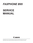
2.1.7 Joystick Port Operation
The joystick port (Register 14 of the Sound Chip - Section
2.1.6.6) is read via an IN-instruction directed at port F6H with
selection of activating data from the left (player 1) or right
(player 2) determined by Address bits 8 and 9 as shown in Figure
2.1.7-1.
In order to address Register 14, a OEH must be written
to port F5H (Sound Generator Address) prior to reading joystick
Section 4.4 describes the software sequence necessary to
data.
control this hardware.
shown
In
the joystick,
t h e example of Figure 2.1.7-1,
schematically in the lower left of the drawing, is composed of a
movable center stick which is pushed up to touch the up-contact
In this
and, therefore, electronically connects pin-8 to pin-l.
state, a read of port F6H with address bit A8 high, causes
actions as follows:
(1)
I:;
(4)
Address A8 high turns on transistor Q8
98 drives cable pin-8 low
The movable center stick of the joystick in contact with
the up-contact results in a conductive path from cable
pin-8 to cable pin-l.
Pin-l low results in a 0 in bit position 0 of the I/O
register via the isolation diode.
The various positions of the stick similarly result in various
bits being read from the I/O register.
Note that +5 volts and ground are available on the connector
+5V logic could be attached to the joystick port.
33
SO
FIGURE 2.1.7-l
JOYSTICK PORT OPERATION
1
I
lz
:
.
: LEFT (Pla7.r lb
l
JOYSTICK
:
:
:
:
:
:
:
:
:
.:.
:
:
:
. l. :
:
i
34
:
.
:
:
:
:.
.
9876
RaGnT (P1ay.c 2)
:
. JOISTlCK
: CONNECTOR
:
.
.
:
:
i
:
:
:
:
:
:
:
:
:
.
:
:
:s4321;
It
1
08
07
1
F@
17
2.1.8 Control Logic
The control logic of the TS2068 is primarily a Standard Cell
Logic Device in a 68-pin JEDEC leaded carrier package and
includes the following major functions:
SECTION
FUNCTION
2.1.8.1
2.1.8.2
2.1.8.3
Bank Selection Logic
Z-80 Clock Generation
Display Timing,
DMA Display
File
Access,
Attribute Control, and Pixel Data Serial Shift
Interruption Generation
2.1.8.4
BEEP Output (See Section 2.1.13.2)
CASSETTE I/O (See Section 2.1.12).
Table 2.1.8-1 provides a description of the
Additionally,
See the System Schematic in
function of each SCLD I/O pin.
Appendix D for pin numbering.
2.1.8.1 Bank Selection Logic
The TS2068 is a Z-80 based computer, therefore it can
directly address only 64K bytes of memory via its 16-bit
Additionally, since the Z-80 has no relocation
address.
or indirection capability, the conventional technique of
extending the memory space available to the Z-80 is bank
The TS2068 provides extended bank switching
switching.
by allowing selection of memory in 8K "chunks" which are
identified by bank number and chunk number as illustrated
in Figure 2.1.8-1 for the internal bank selection logic.
The externally sourced BT (Bank Enable) signal can be
internally
logic to disable the
used by external
controlled memories.
As shown in Figure 2.1.8-1:
(1) The cartridge is selected on a memory access with:
Port FF bit 7 = 0
The HSR at port F4h has a "1" in the bit
::
selected by a decode of Address bits
A13-A15. and
E is high
C.
causing activation of RDSCS (ROS Chip
Select).
35
(2) The EXROM bank is selected on a memory access with:
Port FF bit 7 = 1
The HSR at port F4H has a "1" in the bit
selected by a decode of Address bits Al3
- A15.
E’t! is h i g h
;:
C.
causin the activation of- (Ext. ROM
Enable s
(3)
The Home Bank is selected on a memory access
with
The HSR at Port F4H has a "0" in the bit
selected by a decode of Address bits Al3
- A15.
B'l? is high.
a.
b.
causing the activation of the appropriate
enable signal as detailed below.
To understand the details of the schematic, of Section 2.2 (Appendix D):
(1) SELECT CARTRIDGE of Figure 2.1.8-1 involves activating m to
its low active state
(2) SELECT EXROM of Figure 2.1.8-l involves activating -to its
low active state
(3)
SELECT HOME BANK of Figure 2.1.8-1 involves
a.
b.
C.
d.
Activating
A14=0
Activating
A14-1
Activating
A14-0
Activating
A14=1.
m to its low active state when A15=0 and
m to its low active state when Al+0 and
W to its low active state when Al5=1 and
71As3 to its low active state when Al5=1 and
36
FIGURE 2.1.8-1
BANK SELECTION LOGIC
0
l
*
.----_
._ - --_
;
___
_
-----.
HoRtLowT*L
ELECT MUSTER
t
Port F4h
PatFFbdt 7
TABLE 2.1.8-l
SCLD I/O PIN FUNCTION DEFINITIONS
SYMBOL
NAME
DIRECTION
OF SCLD
IN/OUT
FUNCTION
AO-A7
Al3-A15
Address Bus
DO-D7
Data Bus
KBO-KB4
Keyboard Outputs
A7R
A7+Refresh
out
To refresh and address 8th bit
address line input of RAM memory
(not display) of 32K of 4416
RAM's (Home Bank 8000H to FFFFH)
MAO-MA7
Muxed Adrs.Bus
out
Display memory muxed address bus
and refresh
Ts
Tri-State
Display
Memory Ctl.
out
Tri-State control for
data buffers when CPU
ing display memory at
display controller is
the display memory
OCPU
Clock to CPU
out
CLK - Clock to Z80A CPU which is
interrupted to stop CPU when CPU
wants to address display RAM at
same time as display controller
Read
Direction
Control to
out
To control read/write direction
of 74LS245 Data Bus Buffer between CPU and SCLD
ROMCS
Home ROM
Chip Select
out
To activate the 16K Home ROM
(first 16K) when memory selection
(MS) is set to Home Bank
RASl
Row Address
Strobe #1
out
To activate row address strobe for
display memory only during memory
read/write, refresh and display
read
In
Address Bus lines Input from Z8OA
In/Out
Data Bus inputs/outputs from/to
Z80A through U9-74LS245 or inputs
from display RAM (16K) - U6 and U7
In
Inputs from 5 lines of keyboard
matrix - goes low at one of 8
(active
low)
line
address
sequences on I/O Request
38
address and
is addresssame time
addressing
TABLE 2.1.8-1
SCLD I/O PIN FUNCTION DEFINITIONS
(continued)
SYMBOL
DIRECTION
OF SCLD
IN/OUT
NAME
FUNCTION
CASl
Column Address
Strobe #l
out
To activate column address strobe
for display memory only (2nd 16K)
and
durinq
memory
read/write
display read _
CASZ
Column Address
Strobe #2
out
To activate column address strobe
for Home Bank RAM (3rd 16K 1
CAS3
Column Address
Strobe #3
out
To activate column address strobe
for Home Bank RAM (4th 16K 1
DRAMWE
Dynamic RAM
Write Enable
out
When active low, enables a write
into the display RAM only
MUX
MUX Control of
RAM Address
out
MUX control to 74LS157 (UlO & Ull
to multiplex the row and column
addresses to all dynamic RAM's
V
Chroma Vector V
out
Color vector level for quadrature
(R-Y) input to video modulator
v
Luminance V
out
Luminance
level
rm
Read to CPU
In
CPU is reading from a memory or
I/O location
RR
Write from CPU
In
CPU is writing to a memory or I/O
location
Memory
In
CPU is requesting access to a
memory location to read or write
In
CPU is requesting access to an
I/O location to read or write
Request
I/O Request
39
(briqhtness)
control
TABLE 2.1.8-l
SCLD I/O PIN FUNCTION DEFINITIONS
(continued)
SYMBOL
NAME
DIRECTION
OF SCLD
IN/(JUT
FUNCTION
Refresh
In
CPU is
refresh
generating a
address to refresh dynamic RAM's
Tape Input
In
Magnetic tape signal input
Bank Enable
In
When active low, indicates that
internal
disabled
memory
’
(Home, Extension aniSDock Banks)
and an external memory is in use
Extension
ROM Select
out
Active low chip select signal for
Extension ROM
+5 Volt Power
In
Power (+5Vl input to SCLD
Interrupt to
CPU
out
Interrupts CPU to handle keyboard
strobing and timer for PAUSE command. Open drain N channel with
internal pull-up
RoscS
ROS Chip Select
out
ROM-Oriented Software (Cartridge
Bank) Chip Select
SPKR/TAPE
OUT
Speaker and
Tape Output
out
Digital output to magnetic tape
and to sound amplifier for speaker
output
oc
Clock "C"
out
Clock for sound chip 81.764 MHz.
BDIR
Bus Direction
to Sound Chip
out
A bus direction control signal to
the PSG.
When high the sound
chip either receives a write to
PSG or latches addresses from the
data bus
BCl
Bus Control to
Sound Chip
out
A bus control signal to the PSG.
When high the sound chip either
is read to data bus or latches
addresses from the data bus
Tape In
vcc
40
TABLE 2.1.8-1
SCLD I/O PIN FUNCTION DEFINITIONS
(continued)
SYMBOL
ixc out
OSC In
NAME
OSCl'llator
Out
Oscillator In
DIRECTION
OF SCLD
IN/OUT
out
FUNCTION
Xtal Oscillator amplifier output
to drive crystal
Xtal Oscillator
amplifier
to sense crystal signal
In
input
Chroma Vector U
out
Color vector level for quadrature
(B-Y) input to video modulator
Ground
In
Ground return of SCLD
u
Buffered Clock
out
Buffered CPU clock to outside (Jl
- connector)
R
Red Color Output Out
Produce color signals
monitor (TTL level)
G
Green Color
output
out
Produce color signals to RGB
monitor (TTL level)
B
Blue Color
output
out
Produce color signals to RGB
monitor (TTL level)
U
GND
41
to
RGB
2.1.8.2 Z-80 Clock Generation
The oscillator circuit utilizes an AT-cut quartz crystal
at 14.112 MHz. This oscillator feeds a divide by 4 chain
to generate the 3.528 MHz clock for the CPU (0 CPU).
This clock
runs continuously except when the CPU
addresses the 16K bytes of RAM containing the video
display file at the same time the video display processor
logic requires access to that same RAM.
For this
contention case the CPU clock is stopped in the high
state until the video display processor access has been
completed, then the CPU clock continues in its normal
manner.
2.1.8.3 Display File H/W Control and Timing
The 14.112 MHz oscillator is also used to drive the
counter chain deriving video timing.
By dividing the
14.112 MHz. signal by 896 a 15.75 KHz horizontal sweep
frequency is generated.
The 15.75 KHz signal feeds a
g-stage counter which counts from 0 to 106H (262 decimal)
developing the 60.1145 Hz vertical sync.
See Figure
2.1.8-2.
During each horizontal scan the video display processor
accesses, in the standard video mode, 32 bytes of pixel
data plus 32 bytes of attributes by 32 memory accesses
reading 2 bytes per access in RAM page mode, i.e. the low
order address bits are provided to the RAM once via RAS
activation, then the data byte is read during the first
activation of CAS and the attribute byte is read during
the second activation of CAS. The page mode operation is
completed by deactivating RAS. (See Fiq. 2.1.8-2.)
The accessed pixel data is serially shifted out to the
video generation circuitry at a rate of 1 bit each 142
nanoseconds (7.056 MHz) resulting in the need to fetch a
new data/attribute pair each 1.134 microseconds during
the horizontal
The shifted out pixel
scan time.
information is used to control the selection of the 3
paper color (pixel=0) or 3 ink color (pixel=1) bits to be
qated out as the R, G, and B signals.
When FLASH is
enabled by the attribute byte, the INK and PAPER field
information is swapped at the 1.879 Hz. flash rate.
The
R, G, and B signals control the D-to-A converter which
generates the proper U, V, andToutputs for use by the
1889 to create composite video.
The address information provided to the RAM's duri nq RAS
This
and CAS times is as shown in Figure 2.1.8-2.
address generation logic explains the non-sequential
nature of the video display as described in Section
2.1.10.
42
FIGURE 2.1.8-2
VIDEO DISPLAY PROCESSOR RAM ADDRESS GENERATION
(Normal Video Mode)
DISPLAY PIXEL DATA ADDRESS
Address Bit: 15
Range=
4000H57FFH
\
14
13
12
11
l0
9
8
7
6
54321/0
$flBRQMLKPONIHGFD
/
/\
CASYA
Rk
DISPLAY ATTRIBUTE ADDRESS
Address Bit: 15
Range=
5800H5AFFH
\
14
13
12
11
10
9
8
7
6
5
4
3
21JY
,ffl~ll~RQPONIHGFD
J
/L
v
CAS 1B
RAS
VIDEO TIMING COUNTER CHAIN
MSB
s
t
LINE
R-t)
LSB
LINE
PON
Y PIXEL
(8 Bit Group)
MLI(
1
H
COLUMN
1.764
MHz
lr
(14.112
MHz/8)
Counter
60.1145 Hz
Vert.Sync.
43
2.1.8.4 Interruption Generation (17 ms)
During the vertical blanking interval (once each 15.635
ms) the SCLD, if enabled by the INTEN bit (Bit 6) of I/O
Port FFH, activates the TiJT signal
which directly
A CPU maskable
connects to the m input to the 280.
interruption can then occur, as described in Section
2.1.3.7, if enabled.
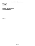
2.1.9 Keyboard
The keyboard for the TS 2068 has forty-two (42) hard keys
with
tactile
feel
utilizing an
(typewriter
style)
over-dead-center type of rubber spring pad and a carbon pill that
hits the P.C. board, just under the keyboard, to short-out a pair
of closely placed precious metal contacts.
The read-out matrix
is an eight by five cross point switching as shown in Figure
2.1.9-1.
Each switch closure connects one of the eight high order address
lines (by going low through a diode) to one of the five input
lines to the SCLD (KBO through KB4).
Scanning is by software algorithm as described in Section 4.1.1.
During the IN instruction, address bits AO-A7=FEH select the
Keyboard I/O port while bits A8-A15 select the particular 5 keys
to be sampled during the particular IN instruction execution.
For example, an IN instruction directed at the keyboard I/O port
with address bit A8 low and A9-A15 high will supply O's on KBO,
KBl, KB2, KB3, and/or KB4 if the CAP SHIFT, Z, X, C, and/or V
keys are respectively denressed.
Note that when reading the I / O port FEH, data bits D5-D7 are not
part of the keyboard information.
Section 2.4.7 details the connection of the keyboard to the main
P.C. board'.
2.1.10 16K Video Display RAM
The 16K-byte video display RAM, composed of two 4416's, is
isolated from the Z80A CPU by the SCLD control logic and buffers
to allow the video display processor to access pixel and
attribute data from the display files independent of the CPU (see
Section 2.1.8.3).
The Video Display RAM is located in Chunks 2 and 3 of the Home
Bank, beginning at 400DH and 600DH respectively. Figure 2.1.10-l
illustrates the organization of the Primary Display File located
same
utilizes
the
file
display
4000H.
The
second
at
Based on the video mode set via Port FFH, the
organization.
video hardware accesses the RAM for pixel data and attribute
control information.
44
Flgure 2.1 .9. KEYBOARD SCHEMATIC
I
I
I
I
:
-
I
DATA B U S
45
FIG. 2.1.10-l
DISPLAY FILE ORGANIZATION (NORMAL MODE)
iI=
can
L
0
C
K
1
3'
4
5
6
7
0
32 BYTES
LINE 0
32 BYTES
!LINE!
401l- 4020 . . . . . . . I4120.......413F
I 4100
4oool 4101:::::411F
4o01
4200 4201 ... ..421 F 4220.......423 F
4300 4301 ... ..431 F 4320.......433 F
4400 4401 ... ..441 F 4420.......443 F
4500 4501 ... ..451 F 4520.......453 F
4600 4601 . . . ..461F 462O.......463F . . . . . . . . . . .
4700 4701 . . . ..47lF 4720.......473F . . . . . . . . . . .
CHAR. CHAR .
CHAR .
POS.
POS.
POS.
o/31
O/O
O/l
I
.
32 BYTES
POS.
8/O
can
P
b
:
3
4
:
2
2
7
POS.
8/l
32 BYTES
POS.
8/31
mto
41E0
42E0
43E0
7/o
32 BYTES
L I N E !
t
40t1 ......
41El .... ..41F F
42El .... ..42F F
43El .... ..43F F
.... ..44F F
.... ..45F F
.... ..46F F
.... ..47F F
CHXR-
POS.
7/31
7/l
03 RYTFC
POS. POS.
15/o 15/l
32 BYTES
32 BYTES
_!V!!!
5000 5001
Wll- 5um . . . . . . .
...........
...........
5100 5101:::::51lF 5120.......51
5200 5201 . . . ..521F 5220.......523F . . . . . . . . . . .
5300 5301 . . . ..531F 5320.......533F . . . . . . . . . . .
5400 5401 . . . ..541F 5420.......543F . . . . . . . . . . .
5500 5501 . . . ..551F 5520.......553F . . . . . . . . . . .
5600 5601 . . . ..56lF 5620.......563F . . . . . . . . . . .
5700 5701 . . . ..571F 5720.......573F . . . . . . . . . . .
CHAR-CH7iR
CHAR .
.
.
POS.
POS.
POS.
1610 16/l
16/31
’
POS.
15/31
32 BYTES
!LrNE!
tu SW1
51E0 51El
52E0 52El . . . . ..52FF
53E0 53El . . . . ..53FF
54E0 54El . . . . ..54FF
55E0 55El . . . . ..55FF
56E0 56El . . . . ..56FF
57E0 57El . . . . ..57FF
CHAR .
CHAR . CHAR .
POS.
POS. POS.
23/31
23/O 23/l
ATTRIBUTE FILE:
2
1 5AOO..... 5AlF( 5A20.....5A3F15A40 . . . . . . . . . . . . . . . . . . . . . 5ADF(SAE0......5AFF]
46
2.1.11 Video Generation
2.1.11.1 Composite Video
The U, V, annsignals from the SCLD are supplied to the
LM1889 and associated circuitry to produce composite
video and modulated RF.
This circuitry produces color
vectors at approximately the following angles:
PHASE
Blue
Magenta
Red
Green
Cyan
Yellow
Reference
TS 2068
(Degrees)
350
64
116
242
284
170
224
NTSC STANDARD
(Degrees)
350
62
112
240
284
170
180
The Front Porch, Sync Pulse, Back Porch, and Color Burst
portions of the composite video signal are illustrated in
Figure 2.1.11-1.
In proper adjustment the following
should be observed:
= 40 +/- 2 IRE units
Sync Pulse
= 35 to 45 IRE units
Color Burst
Color Burst Freq. = 3.579545 MHz.+/-70 Hz
The following three facts may
problems with certain monitors.
aid in understanding
1.
The color burst is not synchronous with the
waveform since it is generated from the 3.579545
MHz crystal and the waveform is derived from the
The result is observed
14.112 MHz crystal.
green to
ripples at color boundaries, e.g.
magenta.
2.
The color burst duration is 8 cycles while
standard TV broadcast stations provide 9 cycles.
This "short" burst is a problem for some monitors.
3.
The color burst starts 6.4 microseconds from the
leading edge of sync. Many monitors are designed
early as 5.3
start as
to
expect
this
microseconds, thus these monitors may not produce
color when attached to the TS 2068.
47
FIGURE 2.1.11-1
COMPOSITE VIDEO SIGNALS
IRE
usec.
2.1.11.2 RF Modulator
The composite video information is used to AM
modulate the selected channel frequency via the
LM1889
and
associated
Channel
tank
2/3
The modulated output is filtered
circuitry.
through the output filter network to reduce
harmonic
generation to
FCC
comply
with
requirements.
The RF circuitry is physically
contained inside the RF-can at the rear left
corner of the PCB (at the RF output jack). 75
ohms is the output impedance.
48
2.1.12 Cassette I/O
See Sections 2.1.13.2, 2.4.3 and 4.2.
2.1.13 Port Map
Table 2.1.13-1 summarizes the I/O addressing of ports utilized by
Details of the data bits of each of these ports is
the TS 2068.
provided by the following sections.
2.1.13.1 Display Enhancement Control (Port FFH)
The display enhancement control register within the SCLD
controls:
a)
Selection of Enhanced Video Modes
b)
Ink selection for 64-Column Mode
Cl
Enable/Inhibit the 17 ms interruption to the Z80
Selection of Extension ROM or Cartridge (see
Section 2.1.8.1)
d)
I r7
D6 1
64-Column Mode
Ink/Paper Selection
000
001
010
011
100
101
110
111
-
Black/White
Blue/Yellow
Red/Cyan
Magenta/Green
Green/Magenta
Cyan/Red
Yellow/Blue
White/Black
Selection
000 - Normal (Primary
Display File)
001 - Second Display File
010 - High Res. Graphics
110 - 64-Column Mode
Other combinations may
produce unpredictable
results.
(Inhibit 17 ms Interruption
(0 to Enable)
EXROM/Cartridge Select
(See 2.1.8.1)
TABLE 2.1.13-1
I/O PORT MAP
PORT
ADDRESS
(HtX1[DnrIMALl(BINARv)
FUNCTION
Display Enhancement FF
Control
255
OPERATION
REFERENCE
11111111
R/W
2.1.10, 2.1.13.1,
3.2.2.3, 5.2
R/W
2.1.9, 2.1.13.2,
2.4.3, 4.1.1, 4.2
Keyboard/Tape I/O
FE
254 11111110
Reserved
FD
253
11111101
Reserved
FC
252
11111100
TS 2040,Printer
FB
251
iiifioii
R/W
2.1.13.3, 4.1.3
Sound Chip &
Joystick Data
F6
246 11110110
R/W
2.1.6, 2.1.7, 2.1.13.4
2.4.4, 4.3, 4.5
Sound Chip Address
F5
245 11110101
W
Horizontal Select
Register
F4
244 11110100
R/W
Same
2.1.8.1
2.1.13.2 Keyboard/Tape I/O (Port FEH)
Port FEH is used to input Keyboard and Tape data and to
output Border color, Tape data, and Sound (BEEP) tones.
READ (IN)
I D’ I D6 I D5 I D4
/\
D3
D2
Dl
DO 1
4
KEYBOARD INPUT DATA
(See 2.1.9)
Not Used (Set to 0)
-TAPE INPUT (See 4.2)
50
WRITE (OUT)
I D’
DS 1 f
Db
I D3 I 02
Dl
DO [
BORDER COLOR - 000
001
010
011
100
101
110
TAPE
111
LOUTPUT
(See 4.2)
hii3-Gv
I- SOUND
OUT
Black
Blue
Red
Magenta
Green
Cyan
Yellow
White
(BEEP )
2.1.13.3 TS 2040 Printer (Port 1XXXXOXX)
The TS 2040 Printer peripheral is written to and status
read from via OUT and IN instructions with Bit 7 = 1 and
Bit 2 = 0 (other bits are not decoded by the printer).
READ (IN)
I D’ I D6 1 Ds
D3
D4
NOT%ED
Printer Not
-Configured
D2
Dl 1 Dq
/
Ready for Next
Pixel
-Start of
Paper
WRITE (OUT)
I
3’!
D6
Db
D3 1 D2 1 Dl 1 DO 1
1‘
I NOT USED
Motor Speed
Select - 0 = Fast
1 = Slow
D4
NoT%SED
Motor ON/OFF
0 = ON
1 = OFF
Pixel to
-Print - 0 = None
1 = Black
51
2.1.13.4 Sound Chip & Joystick (Ports F5H and F6H)
P o r t s F5H and F6H are used to control and access the
Details of the
Sound Generator and the Joysticks.
registers available via these ports is contained f n
Sections 2.1.6 and 2.1.7.
2.1.13.5 Horizontal Select Register (Port F4H)
The HSR addressed via Port F4H is used in the control of
the Bank Switching logic as detailed fn Section 2.1.8.
Each bit, when set, enables the corresponding 8K memory
"chunk" in either the Dock Bank (Port FF, Bit 7=0) or the
Extension ROM Bank (Port FF, Bit 7=1). The HSR must be
set to all zeroes in order to enable the entf re Home Bank.
2.2 Schematic Diagram
Appendfx D contains a detailed schematic diagram of the TS 2068.
2.3 Unit Absolute Ratings
FUNCTION
DESCRIPTION
MIN
MAX
TS
VAC
Ta
Vfn
Storage Temperature
AC Line Voltage
Operating Ambient TW
Voltage on any Logic
Pin
EAR input Peak AC
Input DC Voltage
-40c
105v
OC
-0.3v
+65C
130v
4Oc
+5.3v
-2.0v
14.75V
+5.0v
26V
Vfn (EAR)
Vdc (IN)
2.4 Interfaces and Connectors
The TS2068 has a number of specialized interfaces that are
accessible vi a the following connectors:
CONNECTOR
TYPE
LOCATION
2X32 Card Edge
System Bus
Cartridge
2X18 Card Edge
MIC
l/8" Mini Phone
EAR
l/8" Mini Phone
Player 1 Joystick 9-pin "D"
Player 2 Joystick 9-pin "D"
RCA Phono
Monitor
TV
RCA Phono
Keyboard
14-pin SIP
AC Adapter
52
Right Rear
Under TCC door
Rear
Rear
Left Side
Right Side
Rear
Rear
Inside-Left Rear
Rear
2.4.1 System Bus Connector - Pl
The TS2068 provides a 2 X 32 pin connector, which is
designated as Pl, at the right rear corner of the
console.
The mechanical, functional, and electrical
requirements of the system buss connector are detailed in
the following tables and figures:
FIGURE/TABLE
TITLE
Figure 2.4.1-1
Pl
Mating Connector Mechanical
Requirements
Figure 2.4.1-2
Pl
Signal Layout
Table 2.4.1 - 1 Pl
Signal Definition
Table 2.4.1 - 2 Pl
Signal Electrical
Characteristics
FIGURE 2.4.1-1
Pl MATING CONNECTOR MECHANICAL REQUIREMENTS
64 PIN CONNECTOR
SCALE: NONE
TABLE 2.4.1 - 1
Pl SIGNAL DEFINITION
PIN #
1A
1B
2A
2B
3A
3B
4A
4B
5A
5B
6A
6B
7A
7B
8A
8B
9A
9B
10A
1OB
11A
11B
12A
12B
13A
13B
14A
14B
15A
15B
16A
16B
17A
17B
18A
18B
19A
19B
20A
20B
21A
21B
22A
22B
23A
23B
24A
24B
25A
25B
26A
26B
27A
27B
28A
28B
29A
29B
30A
30B
31A
31B
32A
32B
NOTE:
SIGNAL
NAME
DESCRIPTION
GND
GND
EAR
Signal Ground
Signal Ground
EAR Input
Speaker/Tape Output
Refresh Address Bit 7 Buffered
+15 Volts DC
Data Bus Bit 7
+5 Volts
Daisy In (Not Connected)
__
__
__
Data Bus Bit 0
Power Ground
Data Bus Bit 1
Power Ground
Data Bus Bit 2
CPU Clock (Inverted)
Data Bus Bit 6
Address Bus Bit 0
Data Bus Bit 5
Address Bus Bit 1
Data Bus Bit 3
Address Bus Bit 2
Data Bus Bit 4
Mdress Bus Bit 3
Interrupt Bequest (Active Low)
Address Bus Bit 15, Buffered
Non-Maskable Int.(Active Low)
Address Bus Bit 14, Buffered
CPU HALT Indicator (Active Low)
Address Bus Bit 13, Buffered
Memory Request (Active Low),Bfrd.
Address Bus Bit 12
I/O Request (Active Low), Bfrd.
Mdress Bus Bit 11
Read (Active Low), Buffered
Mdrees Bus Bit 10
Write (Active Low), Buffered
Mdress Bus Bit 9
Bus Acknowledge (Active Low)
Mdress Bus Bit 8
CPU WAIT (Active Low)
Mdresa Bus Bit 7
Bus Request (Active Low)
Address Bus Bit 6
CPU Reset (Active Low)
Address Bus Bit 5
CPU Ml State (Active Low)
Address Bus Bit 4
Refresh (Active Low),Buffered
Daisy Out (Not Connected)
Extension ROM Enable (Active Low)
Color Signal - Red
ROS Chip Select (Active Low)
(Dock Bank Enable)
Color Signal - Green
Bank Enable (Active Low)
Color Signal - Blue
SPKR/TAPE OUT
A7RB
+15v
D7
+5v
DZIN
Not Used
Slot
Slot
DO
GND
Dl
GND
D2
?j
D6
A0
D5
Al
D3
A2
D4
A3
INT
Al5B
N)(I
A14B
HALT
A13B
ffR.PQB
Al2
iinip
A10
YBB
A9
BUSAR
A8
WAIT
A7
BUSRQ
A6
RESBT
A5
iii
A4
RFSHB
DZOUT
EXROM
R
Roses
G
SE
B
IOA5
BUSISO
SOUND
VIDEO
GND
Analog Sound Signal Output(O-5V)
Composite Video Signal Output
Signal Ground
Signal Ground
All A Pins are on component side of board
All B Pins are on non-component (soldering) side of board
55
TABLE -2.4.1-2
Pl SIGNAL ELECTRICAL CHARACTERISTICS
____________
MNEMONIC
A158
A14B
A13B
A12
All
A10
A9
A8
A?
A6
A5
A4
A3
A2
Al
A0
A7RB
IORQB
WRB
RFSHB
EXROMROSCS
%OB
CAPACITIVE
LOADING
MAX
(PF)
30
:o"
30
30
i:
30
30
30
30
::
30
30
30
30
30
30
30
:i
30
30
30
_30
__
30
-_
OUTPUTS
V(OL)
MAX
VOLTS
FROM
TS2068
I(LOAD)
MAX
(MA)
0.5
0.5
0.5
0.4
0.4
1.8
1.8
1.8
8.:
0:4
0.4
0.4
0.4
0.5
0.4
0.4
0.4
0.4
0.5
0.5
0.5
0.5
0.5
0.5
0.5
0.5
0.4
--_
0.4
--0.4
_--
xi
1:8
1.8
1.8
1.8
;::
1'*!
1:B
1.8
1.8
0.35
12
12
12
;:
12
12
1.8
-me
1.8
-_1.8
___
_------e-m
V(OH)
MIN
VOLTS
2.4
2.4
2.4
2.4
24
24
2.4
2.4
2.4
2.4
2.4
2.4
2.4
2.4
2.4
2.4
2.7
2.4
2.4
2.4
2.4
2.4
2.4
2.4
2.4
________________
V(IL)
MAX
VOLTS
0.8
0.8
0.8
0.8
0.8
0.8
0.8
0.8
0.8
0.8
0.8
0.8
0.8
0.8
0.8
0.8
0.8
0.8
0.8
0.8
V(IH)
MIN
VOLTS
2.0
2.0
me-
___
__-
0.8
0.8
0.8
0.8
___
0.8
0.8
0.8
2.0
2.0
2.0
2.0
___
2.0
2.0
2.0
INPUTS
TO
TS2O68
I IN (MAX)
uA
1800
1800
1800
1800
1800
1800
1800
1800
1800
1800
1800
1800
1800
1800
1800
1800
___20
20
20
____
____
20
20
_______-
INPUT
CAPACITIVE
LOADING
MAX (PF)
40
40
40
74
74
74
76
76
72
72
72
12
72
72
72
98
120
10
10
10
-_
__
10
10
10
12
_10
10
10
Hi
:i
E
___BUSAK
2.4
-e-m
--WAIT
___HALT
2.4
____
m-i
____________________________OpEN COLLECTOR WITH PULL-UP ____________________-------------i-m
-_
---_-_-R
50
___
__
--_
-_-8-i
i*:
?i
G
50
50
1:s
2:4
-em
--____
-B
a:4
_______________ TO 75 ohm COAX __________________________________________________________
VIDEO
30
x*:
1.8
2.4
0.8
2.0
20
120
DO
D1
:i
0:4
;*i
2'*:
0.8 0.8
2.0 2.0
20 20
120 120
D2
30
1:8
214
0.8
2.0
120
D3
D4
:I:
8.: D:4
1.8 1.8
2.4 2.4
0.8 0.8
2.0
;8 20
120 120
D5
D6
0"::
1.8 1.8
2.4 2.4
0.8 0.8
22:: 2.0
20 20
120 120
D7
SPKR/TAPE OUT 500
0"::
0.04
0.3-0.5
-__
-em
_--__
EAR
15
1.6
2.4
+/- 1.3 +/- 5.0
---__
SOUND
100
0
m-e
2.5
-0.3
t5.0
me-__
y!!&
-_---w-m
0.8
2.0
--we
10
1 uF WITH 22OK PULL-UP _________________________-_~___~_~~_____~_~__~~~~~~~~~~~~~~~~~~~~~
__
_-_
_---------_
--IOA5
56
2.4.1.1 Attachment of an RGB Monitor
The TS 2068 provides via the Pl rear-edge connector the
ability to attach an RGB monitor for excellent picture
The TTL-level logic signals
clarity and resolution.
appear directly on the rear-edge connector of the TS 2068
-- the necessary synch signals can be derived from the
simple synch stripper/separator circuit described here.
The Schematic of Figure 2.4.1-3 shows the required
Attachment is via the
connections and electronics.
Shielding should not normally
64-pin keyed Pl connector.
be required, but ferrite beads are recommended on each
wire to minimize EMI, TVI, etc.
Circuit Operation - Rl and the base-emitter junction of
Q l operate as a DC restoration circuit with current
flowing only when the composite video input signal from
With the charge
connector pin B31 is at the synch level.
maintained on Cl, Ql conducts only during the synch pulse
During this
interval (not during the color burst time).
conduction interval, the composite synch signal appears
The Q2 stage
in inverted form on the collector of Ql.
simply re-inverts the signal, providing at its collector
a composite synch signal for the connected monitor.
To provide a separated Vertical synch pulse, R5 and C3
filter the output of Ql to partially eliminate the
Horizontal
synch pulses which are shorter than the
The partially filtered inverted
Vertical synch pulses.
signal is re-inverted by Q3, then R6 and C4 complete the
elimination of the Horizontal synch pulses so that a
separate Vertical synch pulse is supplied for the
attached monitor.
Signals R, G, and B from connector pins 827, 828, and B29
can be supplied directly to the attached monitor.
FIGURE 2.4.1-3
l
svDc
01.03:
2N2QOT OR EQUAL
02: PNPPPP
OR EOUAL
COMPOSITE SYNCH
TO MONITOR
u--iirG.0
0
c4
.033yF
TO MONITOR
VERTICAL SYNCH
TO MONITOR
U
R
027 CbR
G
828 0 G
8
e2s 0
B
57
; ]TO MONlTOR
2.4.2
Cartridge Connector - J4
The TS2068 provides a 2 X 18 pin connector (designated J4
on the schematic) under the door at the front right of
the console.
The table and figures listed below detail
the mechanical, functional, and electrical requirements
and limits of the J4 Cartridge Connector.
TITLE
FIGURE/TABLE
Figure 2.4.2-1
J4 Mating PCB Mechanical
Requirements
Figure 2.4.2-2
J4 Signal Layout
Table 2.4.2-l
J4 Signal Definition
Table 2.4.2-2
J4 Signal Electrical
Characteristics
58
FIGURE 2.4.2-l
J4 MATING PCB MECHANICAL REQUIREMENTS
LONG
F~YGLKS
.7F
1.6
-_i c_aw
NOTES:
\ PCBOAPO
(1) Circuit Board Material:
FLGFN C62
Cl/lA2A (94V-0)
Copper 1 or 2 sides
(2) Contact Fingers: Min. 10
millionth MIL-G - 45204 Gold over
.00005 to .OOOlO inch low stress
nickel.
(3) Contact Fingers 2 and 36
should be longer than other
fingers to latch-up when inserted
with power on.
FIGURE 2.4.2-2
J4 SIGNAL LAYOUT
(View from Front)
II
P
z
34
13
5
7
9 11 13 YS 17 19 21 23 25 27 29 31 33 35
59
COMP
SIDE
TABLE 2.4.2-l
J4 CONNECTOR SIGNAL DEFINITIONS
PIN #
1
3”
4
z
;
9
10
11
12
13
14
15
16
17
18
19
SIGNAL NAME
A14B
+5v
Al2
A13B
DO
D7
Dl
A0
02
Al
D6
A2
D5
A3
D3
A15B
DESCRIPTION
Address Bus Bit 14, Buffered
+5 volts DC
Address Bus Bit 12
Address Bus Bit 13, Buffered
Data Bus Bit 0
Data Bus Bit 7
Data Bus Bit 1
Address Bus Bit 0
Data Bus Bit 2
Address Bus Bit 1
Data Bus Bit 6
Address Bus Bit 2
Data Bus Bit 5
Address Bus Bit 3
Data Bus Bit 3
Address Bus Bit 15,Buffered
Data Bus Bit 4
Memory Request (Active Low),Bfrd.
I/O Request (Active Low),Buffered
Refresh Address Bit 7, Buffered
Read (Active Low), Buffered
CPU Ml State (Active Low)
Write (Active Low), Buffered
Address Bus Bit 8
Address Bus Bit 7
Address Bus Bit 9
Address Bus Bit 6
Address Bus Bit 10
Address Bus Bit 5
Address Bus Bit 11
Address Bus Bit 4
Refresh (Active Low), Buffered
Bank Enable (Active Low)
Extension ROM Enable (Active Low)
ROS Chip Select (Active Low)
Gr6D;;k Bank Enable)
&
3
;:
22
23
24
25
26
27
28
29
30
31
32
33
34
35
z!!
36
GND
A8
A7
A9
A6
A10
A5
All
*
60
TABLE 2.4.2-2
J4 SIGNAL ELECTRICAL CHARACTERISTICS
____________
MNEMONIC
A15B
A14B
A13B
Al2
All
A10
A9
A8
A7
A6
A5
A4
A3
A2
Al
A0
A7RB
ROSCS
g3B
IORQB
iii%
RFSHB
EXROM
iii
DO
D1
D2
D3
D4
D5
D6
D7
CAPACITIVE
LOADING
MAX
(PF)
OUTPUTS
V(OL)
MAX
VOLTS
________________
FROM TS2068 ----------
I(L0AT.I)
MAX
(MA)
30
30
30
30
0.5
0.5
0.5
0.4
30
::
30
30
30
30
30
30
30
30
i::
f?:
0:4
0.4
0.4
0.4
0.4
0.4
0.4
1.8
1.8
1.8
1.8
1.8
::
:i
30
30
30
K
0:4
0.5
0.5
0.5
0.5
30
30
30
30
30
30
i::
0.5
0.4
0.4
0.4
0.4
A.835
1:8
1.8
1.8
12
12
12
12
12
1.8
1.8
1.8
1.8
30
30
30
30
___
0.4
0.4
0.4
0.4
5.25
_-
1.8
1.8
1.8
1.8
1.8
;*:
118
1.8
::i
1.8
300
___
V(OH) I(LOAD)*V(IL)
MIN
MAX
MIN
VOLTS (uA)
VOLTS
2.4
2.4
2.4
2.4
2.4
2.4
2.4
2.4
2.4
2.4
2.4
2.4
2.4
2.4
2.4
2.4
2.7
2.4
2.4
2.4
2.4
2.4
2.4
2.4
2.4
V(IH)
MIN
VOLTS
TO
TS2068
I IN (MAX)
uA
________
INPUT
CAPACITIVE
LOADING
MAX (PF)
10
10
10
10
10
10
10
10
10
10
10
10
10
10
10
I?
10
10
10
10
10
10
10
10
2.4
2.4
2.4
0.8
0.8
0.8
i:8
2.0
2.0
2.4
2.4
2.4
2.4
4.75
___
0.8
0.8
0.8
0.8
2.0
61
INPUTS
2.0
15
15
15
15
120
120
120
120
1:
15
15
120
120
120
120
2.4.3
Cassette I/O
The EAR and MIC connectors provided on the rear of the
l/8"
requiring
TS2068
mini-phone
jacks
are
l/8"
mini-phone plugs as mating connectors.
The MIC output is filtered by a low-pass filter with a
breakpoint of 2.5KHz and provides a signal output of 0.15
to 0.67 V p-p.
The EAR input is filtered by a low-pass filter with a
breakpoint of 23 KHz.
Input voltaqes should be between
4.0 and 10.0 V p-p.
2.4.4
Joystick
The joystick input connectors, one on each side of the
TS2068 case, are standard D-pin "D" type connectors for
use with 5-switch type joysticks.
Connector layout and the function of each pin is given in
Figure 2.4.4-l and Table 2.4.4-1, respectively.
FIGURE 2.4.4-l
JOYSTICK CONNECTOR
62
TABLE 2.4.4-l
JOYSTICK CONNECTOR SIGNAL ASSIGNMENT
P/N
SIGNAL NAME
FUNCTION
I/O PORT BIT
1
STICK UP
2
STICK DOWN
3
STICK LEFT
4
STICK RIGHT
5
--_
not used
6
RUTrON
PUSH BUTTON
&
5v
5 VOLT POWER
8
READ STROBE
ADDRESS BIT 8 OR 9*
9
GND
POWER GROUND
*When Address Bit 8 is high, the READ strobe to the left joystick is
When address Bit 9 is high, the READ strobe to the right
driven low.
joystick is driven low.
2.4.5
AC Adapter Power Plug
The AC Adapter provided with the TS 2068 provides unregulated DC
to the unit as described in Section 2.1.1 Mechanical details of
the plug which mates to the TS 2068 are shown below:
63
2.4.6
Composite Monitor Output
The MONITOR output on the rear of the TS2068 provides a 1
V p-p (+/- 20%) composite color video signal output to an
RCA phono jack which is mated by a standard phono plug
into a 75 ohm coax cable. See Section 2.1.11.1.
2.4.7
RF Output
The TV output on the rear of the TS2068 provides a
modulated color video signal on VHF Channel 2 or Channel
3 as selected by the channel select switch on the bottom
of the unit.
Connection to the RCA phono jack output
should be via a standard phono plug and 75 ohm coax
cable. See Section 2.1.11.2.
Channel frequencies provided are
Channel 2
Channel 3
55,250 +/- 100 KHz
61,250 +/- 100 KHz
Output levels are less than 3 milliwatts as limited by
the Federal Communications Commission.
2.4.8
Keyboard Interface - J9 Connector
Located on the PCB inside the TS 2068 is a 14-pin
single-in-line flex cable connector (AMP TRIO-MATE P/N
l-520315-4 or equivalent). Signals are as listed below:
PIN
SIGNAL
0
1
GND
KBO
KBl
KB2
KB3
KB4
CR6/All
CR7/A10
CR8/A9
CR9/A12
CRlO/Al3B
CRll/A8
CRl2/A14B
CR13/A15B
3'
4
:
:
1:
11
12
13
Any modification to or replacement of the keyboard supplied must
consider the following:
(1)
Contact resistance less than 200 ohms.
(2)
Bounce less than 10 ms.
(3)
Capacitance per line less than 20 pF (0 or 1 key
depressed); less than 40 pF (more than 1 key depressed).
64
3.0
SYSTEM SOFTWARE GUIDE
3.1
Identifier
Location 13 (13H) of the Home Bank ROM is used to identify the
The initial version is
revision level of the System Software.
identified by this location having a value of 255 (FFH).
Any
subsequent versions will decrement this value by 1, e.g., the
first revision would be identified by a value of 254 (FEH). This
identifier should be used to conditionally apply patches or
execute "work-arounds" identified as necessary with a particular
version of the System Software.
3.2
ROM Organization and Services
3.2.1
Home ROM
3.2.1.1
Fixed Entry Points
Home ROM Location 0 is the entry to the system
initialization code upon power-up (Ref. Figure
Locations 8 through 48 (8H through
1.1-4).
30H) are the Z80 RESTART entry points for the
following functions:
RESTART
FUNCTION
8
ERROR - Error exit from BASIC
(Address on Stack points to Error
Number)
15
WRCH - Write Character (Code in
A) to Current Output Channel as
established by SELECT (Address of
to by
routine
pointed
output
System Variable CURCHL).
(See
Section 4.0).
24
IGN SP - Return in A the current
significant
character in
the
Program Line (Address in System
Variable CH ADD) skipping over
a n d - control
characters
spaces
except End-of-Line (ODH=ENTER)
65
32
NXT_IS - Like IGN SP but returns
in
A
Significant
the
Next
Character.
40
CALCTR
Routines .
48
COPYUP - Make room for BC Bytes
of
temporary
workspace
just
before address in System Variable
STKBOT by
memory
copying up
between there and the address in
STKEND,
adjusting
affected
pointers.
Returns DE=lst Byte of
Space; HL=Last.
Entry
to
Calculator
Location 56 (38H) is the entry to service the
hardware generated interruption which occurs
approximately every l/60 of a second (16.67
Z80 Int.
Mode 1 is
This
used.
ms).
interruption is used to scan the keyboard (call
to routine UPD K - see Section 4.1.1).
It is
also used to update the Frame Counter (3 bytes
pointed to by the System Variable FRAMES) used
by the RANDOMIZE instruction.
Location 102 (66H) is the entry point for the
NMI interruption, but this interruption is not
used in the TS2068 design.
(See Section
2.1.3.8 NMI Interruption.)
3.2.1.2 BASIC AROS Support
BASIC Application Cartridges are supported by
special code in the Home ROM.
A program line
is copied from the cartridge to a buffer in the
Home RAM (ARSBUF) and is then executed from
there by the BASIC Interpreter.
When a READ
command is executed, the line containing the
appropriate DATA statement is also copied from
the cartridge to the RAM. The cartridge memory
is enabled only fur search and copy operations
for both program lines and DATA statements, and
when executing a USR function, otherwise the
entire Home Bank is enabled while executing in
the BASIC Interpreter. There is no support for
User-Defined
Functions
which
insert
the
expanded definition parameters directly into
the program and then require search of the
program area to find these parameters whenever
a function is invoked.
See Section 5.1, Cartridge Software/Hardware,
for additional details on BASIC AROS.
66
3.2.1.3
General
The balance of the Home ROM contains the BASIC
Interpreter and standard I/O routines w i t h the
exception of the cassette I/O which is in the
Extension ROM.
The bit map table for the
standard character set is located at the end of
the Home ROM from location 15616 to '16383
(3DOOH to 3FFFH).
The address of this table
minus 256 (lOOH) is contained in the System
Variable CHARS (=3COOH).
The Home ROM routines accessible via the
Function Dispatcher are described in Table
3.3.4-2.
See Appendix A for the ROM Maps
giving the ROM addresses of these routines.
3.2.2 Extension ROM
3.2.2.1
Fixed Entry Points
Extension ROM Location 0 contains code to pass
control to the initialization code in the Home
ROM. (Figure 1.1-4).
Extension
ROM Location 56
(38H) is the
interruption fielder. Control is passed to the
System RAM code (See Section 3.3.3) to bank
call
switch to
Home
Bank
and
the
the
interruption service routines after which the
state of the machine is restored and control
Figure
returns to the interrupted process.
3.2.2-l shows the Extension ROM Interruption
Fielder code.
3.2.2.2 General
The balance of the Extension ROM contains the
following major components:
- Final Phase of System Initialization
(See Figure 1.1-4)
- Cassette tape I/O (see Section 4.2)
- Change Video Mode Service
- OS RAM routines including the Function
Dispatcher (copied to RAM at System
Initialization) (see Section 3.3.3)
- Function Dispatcher Jump Table
67
FIGURE 3.2.2-l
Extension ROM Interruption Fielder
LOCAT ION
OBJECT CODE
SOURCE CODE
0038
0039
003A
003D
003E
003F
0041
0042
0045
0046
F5
F3
3AC25C
A7
00
2804
Fl
C36EFA
Fl
C3AE62
PUSH
DI
LD
AND
NOP
JR
POP
JP
CHK3 POP
JP
AF
A,(VIDMOD)
A
Z,CHK3
AF
INT7
AF
INT3
COMMENTS
Save AF
Disable Ints.
Test Vidmod
Vidmod=O
Restore AF
Chunk 7 if Vidmod not 0
Restore AF
Chunk 3 if Vidmod = 0
3.2.2.3 Video Mode Change Service
The routine CHNG VID takes as input a single
byte in Register3 which designates the desired
video mode as shown in Table 3.2.2-1.
All
non-zero values involve access to the second
display file located at 6000H-7AFFH.
When the
mode change requires remapping of the RAM (see
Figure 1.1-3), the necessary relocation (BASIC
program, machine stack, OS RAM code, UDG area,
etc.) and modifications (system variables, RAM
code internal addresses, stack pointer, etc.)
are done by this service.
The desired video
mode is written to Port OFFH, Bits O-5, and the
System Variable VIDMOD (5CC2H) is updated. The
second display file is cleared to zeros on
initial access (for Dual Screen Mode and High
Resolution Graphics Mode, this results in a
black screen since 0 yields attributes of black
ink on black paper).
If there is not enough
free memory to do the necessary remapping,
Error 4, Out of Memory is given.
via
Access
service
the Function
to this
Dispatcher cannot be made consistently for
An Interface Routine is given
various reasons.
in Section 3.2.2.4, to be executed from the
Home RAM, which provides access to the Video
Mode Change Service as well as other Extension
ROM routines.
See Sections 4.1.2 and 5.2 for discussion of
video screen support software.
See Section 6.4
for details on known problems and corrections
related to the Video Mode Change Service.
68
TABLE 3.2.2-l
INPUT TO VIDEO MODE CHANGE SERVICE
VALUE
IN A
VIDEO
MODE
0
Normal
Primary Display File Only(Close
2nd Display File if Open)
128
(80H)
Dual
Screen
Two Display Files Available.
Primary Display File Active at
Screen.
1
Dual
Screen
Two Display Files Available.
Second Display File Active at
Screen
2
High Resolution
Graphics
Primary Display File contains
Second
data for 256X192 pixels.
6144
File
contains
Display
one
each
Bytes,
Attribute
controlling 8X1 pixels. NOTE 1.
64-Column
Ink
Paper
The two display files are combined to provide a 64 column X
24 line screen. Even columns
are derived from data in the
Primary Display File and odd
columns from the 2nd Display
File.
Bits 3-5 of the mode select the
ink color which determines the
complementary paper color.
The Flash and Bright Attributes
are fixed at 0; the Border is
fixed at the paper color.
NOTE 1.
Black
White
14
(OEH)
Blue
Yellow
22
(16H)
Red
Cyan
30
(lEH)
Magenta
38
(26H)
Green
Magenta
46
Cyan
Red
54
(36H)
Yellow
Blue
62
(3EH)
White
Black
6
(2EH)
NOTE 1:
DESCRIPTION
Green
The areas of memory normally used for Attribute Bytes are not
accessed by the video hardware in this mode.
69
3.2.2.4
Extension ROM Interface Routine
The Extension ROM routines W TAPE (Write from
RAM to Tape), R-TAPE (Read from Tape to RAM)
(see Section 4.2) and CHNG VID (see Section
3.2.2.2) may be of interest to the machine code
programmer. Because of a conflict with the use
of the IX Register, the tape routines cannot be
via
the
Function
successfully
accessed
Because the Change Video Mode
Dispatcher.
Service may involve relocating the OS RAM
routines (including the Function Dispatcher),
it also cannot be
and for other reasons,
the
Function
using
accessed
consistently
Figure 3.2.2-2 gives a sample
Dispatcher.
routine, to be executed from the Home RAM,
which can be used to bank switch to the
Extension ROM and call directly to the desired
Appendix A contains an Extension ROM
service.
Map giving the addresses of these and other
routines.
70
FIGURE 3.2.2-2
EXTENSION ROM INTERFACE ROUTINE
=OOFC
=0068
=OE8E
=5CC2
0000’
0003'
0006'
0008’
000B'
OOOE'
21 OOFC
cc 0020'
18 17
21 0068
cc 0020'
18 OF
0010' 21 OE8E
1313' F5
0014' CD 0020'
0017'
0018'
00111'
001C'
OOlF'
0022'
0024'
0026'
0028'
F1
FE 80
20 03
32 5CC2
3A OOLC'
03 FC
00 FF
CB BF
03 FF
OOZA'
0023'
FB
c9
002C'
00
0020'
OOZE'
OOZF'
F3
F5
00 FF
0031'
0033'
0035'
0437'
0036'
003C'
003:'
033F'
CB
03
D9
32
3E
03
Fl
E9
FF
FF
FC
OOZC'
01
F4
1
2
3
4
5
6
7
8
9
10
11
12
13
14
15
16
17
18
19
20
21
22
23
24
25
26
27
28
29
3:
32
33
34
3s
36
37
38
39
40
Cl
42
43
44
45
46
47
48
49
53
54
55
56
57
58
59
60
61
62
63
64
65
:
R_lAPE
W_TAPE
CHNG_VID
VIDMOD
7
:
EQU
EQU
EQU
EQU
;
;
;
;
;
OOFCH
0068H
0E8EH
5CC2H
..
:
READTP
; CALL READTP WITH REGISTERS SET
; UP FOR R_TAPE ROUTINE
LO
CALL
JR
:
:
;
WRITTP
:
HL,R_TAPE
IFRTN
EXIT
; ADDRESS TO HL
; ENABLE EXT./EXECUTE QTN
; RESTORE HOME BANK A N D R E T U R N
; CALL WRITETP WITH REGISTERS
; UP FOR W_TAPE ROUTINE
LO
CALL
JR
:
:
:
:
:
..
EXIT
:
HSSAVE
:
IFRTN
:
SET
; ADDRESS TO HL
;
HL,W_TAPE
If RTN
EXIT
; CALL CHGVID WITH DESIRED VIDEO
; MODE IN A
t
.
CHGVID
EXTENSION R O M INTERFACE
ROUTINE
READ TAPE ROUTINE
WRITE TAPE ROUTINE
C H A N G E VIDEO MODE ROUTINE
VIDEO M O D E SYSTEM VARIA8LE
LD
PUSH
CALL
HL,CHNG_VID
AF
IFQTN
; ADDRESS TO HL
; SAVE VIDEO MODE
;
;
;
;
;
POP
CP
JR
LO
AF
80H
NZ,EXIT
(VIDMOD),A
LO
OUT
IN
RES
OUT
EI
RET
A,(HSSAVE)
(0F4H),A
A,(0FFH)
7,A
(0FFH),A
DEFB
0
DI
AF
A,(0FFH)
7,A
(0FFH),A
A,(0F4H)
(HSSAVE),A
A,1
(0F4H),A
AF
(HL)
PUSH
IN
SET
OUT
IN
LD
LD
OUT
POP
JP
END
71
COMPENSATE FOR 'BUG' I N
CHNG_VID RTN.WHICH SETS
VIDMOD=0 INSTEAD OF 80
WHEN BOTH DISPLAY FILES
ARE OPEN
; TEST VIDEO MODE
; TEST IF 80
;
;
;
;
;
SET VIDMOD=80H
GET PREV. HOR.SEL.
RESTORE
READ PORT FF
TURN OFF RCM SEL.
;
SAVE
HOR.SEL. ( P O R T OF4H)
; MASK INTERRUPTIONS
; PRESERVE REG. A
; EXT.ROM
SELECT BIT
; SEL. EXT.ROM
;
;
:
;
;
;
:
HORIZONTAL SELECT FCR DOCK/EXT
SAVE
SELECT CHUNK 0 IN EXT.ROM
RESTORE REG. A
EXECUTE TARGET ROUTINE AND
R E T U R N TO CALLER CF IFRTN
3.3 RAM Organization and Services
3.3.1 System Variables
RAM beginning at 23552 (5COOH) is dedicated to the BASIC
System Variables as defined in Appendix D of the TS 2068
User Manual and in Appendix B of this document. The area
from the end of the defined variables (STRMNM - 23755
(5CCB) ) to 24297 (5EE9H) is reserved for expansion of
the System Variables, but is not used by the Operating
System in the current TS 2068.
3.3.2 System Configuration Table
The area from 24298 (5EEAH) to 24575 (5FFFH) is reserved
for the System Configuration Table (SYSCON). This table
is built at system initialization time and is comprised
of an 8 byte entry for AROS, a 4 byte entry for LROS,
followed by eleven 24-byte entries for proposed expansion
banks and an End-of-Table marker.
In the original TS
2068 the actual usage of this table is limited to the 12
bytes for software cartridge identification (see Section
5.1 for details of the LROS and AROS Overhead Bytes).
3.3.3 Machine Stack
The TS 2068 reserves 512 (200H) bytes of RAM for the
Machine Stack. The Machine Stack pointer is initialized
to a value of 6200H (value also in System Variable
MSTBOT); the pointer is decremented as items are pushed
onto the stack (the pointer may also be modified directly
While the area reserved for the stack
by software).
extends to 6000H, there is no actual check made to
enforce this limit.
Note that the Machine Stack is located in the same memory
The CHNG VID routine
area as the second display file.
relocates the stack to the memory area from OF7COH to
OF8BFH,
and modifies the Stack Pointer and MSTBOT
(OF8COH), as well as other affected system variables,
when initializing the second display file.
(See Section
3.2.2.3.)
3.3.4 OS RAM Routines
The code for the following Operating System functions is
copied from the Extension ROM to Chunk 3 of the RAM at
Since this is in the same
System initialization time.
memory area as the second display file, this code must be
relocated, along with the machine stack, if the second
The CHNG VID routine does
display file is to be used.
(Section
the necessary relocation and modifications.
3.2.2.3.)
72
Because this code is not in a fixed location, access to
the OS RAM routines is conditional on the current video
mode.
The standard technique employed is to test the
value in the System Variable VIDMOD at location 23746
(5CC2H).
A zero indicates that the second display file
is not in use and that the OS RAM routines are therefore
in Chunk 3; any non-zero value indicates that the
routines are in Chunk 7.
YOTE:
This design implies that Chunks 2, 3 and 7 are
always enabled in the Home Bank RAM whenever
the System ROM and/or RAM routines are being
used.
The OS RAM routines are contained in Module "Dispatch"
which is included in Appendix A.
3.3.4.1 RAM Interruption Handler
Chunk 3 Entry: 62AEH
Chunk 7 Entry: FA6EH
The user must enter with bank status and Z80
registers intact, with address from point of
interruption on the stack.
The R A M interruption handler saves state,
including memory selection, enables the Home
Bank, updates the Frame Counter, calls the
keyboard scan routine in the Home ROM, restores
state, and returns to the interrupted process.
The RAM Interruption handler is used whenever
the interruption occurs while the Extension ROM
is enabled,
See Figure 3.2.2-1, Extension ROM
Interruption Fielder.
This same technique can
he used for interruption processing in another
if an LROS wanted to use the
bank, e.g.
standard system ROM keyboard scanning routines.
3.3.4.2
RAM Service Routines
Table 3.3.4-l lists the RAM service routines
which are designed to facilitate communication
Those with Service Codes
between memory banks.
are accessible via the Function Dispatcher.
73
TABLE 3.3.4-l
OS RAM SERVICE ROUTINES
LABEL
SERVICE COOE
(Decimal)
.
.
-
6316
FAD6
Returns in HL the word from the
address in HL in
bank
the
specified in B.
6336
FAFB
Writes the word in DE to the
address in HL in
bank
the
specified in B.
6405
FBC5
Returns current memory selection
(Horizontal
Select byte - low
active) in C
for
bank
the
Preserves Bank #
specified in B.
in B for Home, Ext. or Dock.
644D
FCOD
Returns a single byte mask in A
with all bits 0 except the one
corresponding to the chunk for
the address in HL.
GET-WORD
PUT- WORD
GET STATUS
14
GET-CHUNK
LOCATION
DESCRIPTION
GET NUMBER
15
645E
FClE
Returns in Reg. A the bank number
currently controlling the address
in H L .
BANK
ENABLE
-
6499
FC59
Enables
memory
selected
the
(Horizontal
Select byte - low
active) in the specified bank.
(Bank # in B; Mem.Sel.in C)
GOT0
BANK
-
6572
F032
Transfers
control
to
the
specified address after enabling
memory
selected in
the
the
specified
bank.
Parameters
passed on stack by pushing target
address, then Bank #/Mem.Select
calling
GOT0 BANK.
prior to
(Return address is discarded).
CALL
BANK
-
65D0
FD90
GOT0 BANK except
Like
saves
current hankstatus, calls target
restores
status
address,
and
prior to returning to user.
Two
additional parameters are passed
on stack prior to doing call to
CALL BANK.
These are PRM OUT
(16-bits) following by PRf~.fIbr[~~
described
bits) as
Function Dispatcher.
74
TABLE 3.3.4-l
OS RAM SERVICE ROUTINES
(continued)
LABEL
XFER
SERVICE CODE
(Decimal)
BYTES
-
LOCATION
6722
DESCRIPTION
FEE2
Copies n byte(s) from specified
source to specified destination
in either ascending or descending
Source and destination
order.
can be in the same or different
banks and can be in shadowing
chunks, but neither source nor
destination can pass a "chunk"
(8K) boundary since only the
chunks containing the starting
source and destination addresses
are explicitly enabled.
Parameters passed on stack by
pushing:
Source Bank/Dest.Bank
Source Address
Dest. Address
Length
O/Direction:
(O=Asscending
-l=Descending)
NOTE:
See Appendix A for listing of these routines.
known corrections to the routines.
75
See Section 6.0 for
3.3.4.3
Function Dispatcher
Chunk 3 Entry:
62OOH
Chunk 7 Entry: F9COH
The Function Dispatcher provides, a common
interface to a number of system routines via a
Service Code and Jump Flag parameter passed on
the machine stack.
Table 3.3.4-2 lists the
routines in Service Code order.
Codes for
routines that are known to not be successfully
accessible via the Function Dispatcher have
been deleted (marked Reserved). However, there
is no guarantee that those on the list can be
accessed without problems.
Some ROM routines
require data in a particular format, e.g. BASIC
floating point number(s), both standard and
special integer format, on the Calculator Stack
which is located between (STKBOT) and (STKEND)
(see Appendix C of the TS 2068 User Manual).
An effort has been made to include information
but some
on register usage and functionality,
of the ROM routines are so tightly tied to the
BASIC Interpreter that they would require
analysis which is beyond the scope of this
document.
These have been flagged with an
for
the
list
included in
Asterisk,
but
Most
of
the
documentation purposes only.
routines which are directly implementing a
BASIC command or function have two different
action sequences based on the INTPT Flag (Bit 7
of FLAGS) which distinguishes syntax checking
(Flag=O) from actual execution (Flag=l).
In order to use the Function Dispatcher, first
set up any memory and stack (both machine
and/or calculator) locations as if invoking the
Then
the
directly.
push
service
desired
parameter(s) for the Dispatcher on the machine
Finally,
stack in the order outlined below.
set up the registers as if invoking the desired
service directly and call the Dispatcher based
on its current location (Chunk 3 if VIDMOD=O or
Chunk 7 if VIDMOD has a non-zero value).
1.
PRM OUT
16 bits - Number of bytes of parameter data
being passed on the stack to the specified
Zero
Service (number of stack "pushes" * 2).
if no parameters being passed. E.g., to pass 4
bytes:
76
LD HL,4
PUSH HL
This parameter is passed to the Dispatcher only
if the Jump Flag (SVC CODE) Bit 15) is not
NOTE:
This parameter refers to machine
set.
stack entries only, not to the Calculator Stack.
2.
PRM IN
16 bits - Number of bytes of parameter data to
be passed back from the specified Service
(number of stack "pushes" * 2). Zero if no
parameters to be passed back.
This parameter is passed to the Dispatcher only
if the Jump Flag (SVC CODE Bit 15) is not set.
NOTE:
This parameter-refers to machine stack
entries only, not to the Calculator Stack.
3.
SVC_CODE 16 bits - Bits O-14 identify the Service to be
invoked.
Bit 15 (Jump Flag) is set if no
return is desired (jump to Service rather than
Bit 15 is zero if return is desired.
call).
E.g, to call K SCAN using Service Code 136:
LD
HL,136
PUSH HL
or
LD
HL,88H
PUSH HL
Addendum To TS 2068 Function Dispatcher Services:
On page 84, COLOR and HIFLSH (service codes 85 and 86)
cannot always be accessed through the Function Dispatcher, due to resetting of the carry flag by the FD.
COLOR may be accessed by setting the registers as described in the manual, and then coding CALL #23DE.
HIFLSH can be accessed similarly by coding CALL #2410.
77
TABLE 3.3.4-2
TS 2068 FUNCTION DISPATCHER SERVICES
SERVICE
SERVICE CODE
1 - 13 (l-ODH)
DESCRIPTION
Reserved
GET STATUS
14
(0EH)
Memory
Returns
Selection (Low
Active) in C for Bank # in B
GET NUMBER
15
(0FH)
Returns Bank # in A for Address
in HL
Reserved
16-24 (10-18H)
(See
UPD K
25
(19H)
Keyboard
Process
Section 4.1 . 1 )
PARP
26
(1AH)
Generates DE+1 Cycles of a Tone
Period 8N+236 to
the
having
8N+246 T-States. HL=N. (See 4.4)
BEEP
27
(1BH)
processes
BEEP
Command
parameters on Calculator Stack.
Exits via PARP. (See 4.4)
K-DUMP
28
(1CH)
Primary
Command.
COPY
Dumps
Display File to Printer.
(See
4.1.3)
SENDTV
29
(1DH)
Screen/Printer.
Char.Output
to
Character Code in A. (See 4.1.2)
SETAT
30
(1EH)
Set Print Position to value in
B=Line N o . (O-23); C=Column
/::
(O-31)
ATTBYT
31
(1FH)
Set Attribute Byte for Display
File Adrs. in HL using ATTR_T,
MASK_T and P-FLAG.
R ATTS
32
(20H)
Info.
Attribute
Permanent
Temporary Attribute Variables
CLLHS
33
(21H)
Cl ear
CLS
34
(22H)
Entire
Clear
Display File)
DUMPPR
35
(23H)
Print/Clear Print Buffer.
4.1.3)
Lower
Display File)
78
Input
Screen
to
(Primary
Screen(Primary
(See
TABLE 3.3.4-2
TS 2068 FUNCTION DISPATCHER SERVICES
(continued)
SERVICE
PRSCAN
SERVICE CODE
36 (24H)
DESCRIPTION
S d S (32 b t 1 t
Printer.
PyIel l?:Fa Addre!se:n Hy
of Scans remaining in B (Y%r
(See 4.1.3)
DESLUG
37 (25H)
Remove Number Slugs from Edit
Line Buffer (Address in HL)
K NEW
38 (26H)
NEW command.
INIT
39 (27H)
Initialize:
DE=Maximum
RAM
A=0 for Power-On; = -1
Address.
(FFH) for NEW.
(See Fig.l.l-4)
INCH
40 (28H)
Character to
Input
Selected
currently
Returns NC if no input.
SELECT
41 (29H)
Select Channel (Stream) - # in
A. (See 4.1)
INSERT
42 (2AH)
Insert BC Bytes before byte whose
address is in HL. Copies up all
from HL to (STKEND) and updates
affected
system
variables.
Returns BC=O;
DE=adrs.of last
inserted
byte
of
space;
HL=adrs.of byte before first.
RESET
43 (2BH)
Reset Calculator Stack.
=(STKBOT)
(STKEND)
(MEM)=MEMBOT (5C92H).
CLOSE
44 (2CH)
CLOSE # Command.
Calculator Stack.
CLCHAN
45 (2DH)
BC=Value from
Close Channel.
STRMS (Index into CHANS).
OPEN
46 (2EH)
Channel # an4
OPEN # Command.
Device Spec. on Calculator Stack
OPCHAN
47 (2FH)
Device Spec. on
Open Channel.
DE=pointer
Calculator
Stack.
into STRMS based on Ch.#.
See Fig. 1.1-4
A
from
Channel.
Sets
and
Channel # on
(See 4.1 for more info. on OPEN
and CLOSE)
79
TABLE 3.3.4-2
TS 2068 FUNCTION DISPATCHER SERVICES
(continued)
SERVICE
CAT
SERVICE CODE
48 (30H)
DESCRIPTION
CAT Command (Not Applicable)
ERASE
49
(31H)
ERASE Comnand (Not Applicable)
FORMAT
50
(32H)
FORMA T
MOVE
51
(33H)
MOVE Command (Not Applicable)
FLASHA
52
(34H)
Flash
Char.in
SENDTV;
(Calls
Screen selected.
Cursor.)
FIND -L
53
(35H)
Find BASIC Program Line with the
number in HL.
If Line found,
returns Z and Address of Line in
else
returns
NZ and HL
HL,
contains either address of line
with next larger line number or
points to the Variables area if
there is no larger line number.
Requested Line No. returned in BC
and Address of Preceding Line in
DE (DE=HL if no preceding line).
SUBL IN
54 (36H)
Command (Not Applicable)
A to
Screen.
assumes
Lower
Used to Flash
Finds either the D'th statement
(D=Statement #; E=O)
or
1st
statement
whose
keyword
token
matches
E
(D=O), in a line
pointed to by HL.
If the D'th
statement is found, returns Z and
HL and (CH ADD) both point to 1
byte before-statement.
(If l i n e
contains exactly D-l statements,
then the next line counts as the
If match on E is found,
D'th.).
then returns NZ,NC and both HL
and (CH ADD) point to keyword. D
is decremented by the number of
statements looked at (e.g. D= -2
if two statements).
If no match
on E then returns NZ,C with both
(CH ADD) pointing t o
HL and
End-of-Line byte (ODH).
80
TABLE 3.3.4-2
TS 2068 FUNCTION DISPATCHER SERVICES
(continued)
SERVICE
RECLEN
SERVICE CODE
DESCRIPTION
55 (3/H)
Returns in BC the lenqth of the
record pointed to by HL.
Sets DE
The record can be a
to HL+BC.
program line, or a string or
numeric variable or array.
DELREC
56
(38H)
Delete record pointed to by HL
having length BC from Program or
Variables
memory.
Updates
affected system variables.
PUT BC
57
(39H)
Converts number in BC from binary
to ASCII and outputs to currently
selected channel,
If BC less
than 0, outputs a 0.
SYNTAX
58
(3AH)
syntax of
command or
Check
program line in Edit Line Buffer
(E LINE).
ERR NR= -1 if no
errors, otherwisecontains Error
Number-l.
EXCUTE
59
(3BH)
Execute command(s) from Edit Line
buffer.
FOR
60
(3CH)
FOR command. *
STOP
61
(3DH)
STOP command.
Does RESTART 8
with Error No. 9.
NEXT
62
(3EH)
NEXT command. *
READ
63
(3FH)
READ command. *
DATA
64
(40H)
DATA statement. *
RESTBC
65
(41H)
RESTORE command - Line No. in BC
RAND
66
(42H)
RANDomize command.
Sets seed for
Random Number Generator based on
Parameter
on Calculator Stack.
If parameter is non-zero, value
is loaded to SEED; if zero, value
in FRAMES is loaded to SEED.
TABLE 3.3.3-2
TS 2068 FUNCTION DISPATCHER SERVICES
(continued)
SERVICE
CON'T
SERVICE CODE
67 (43H)
DESCRIPTION
CONT command.
Loads values from
OLDPPC and OSPPC to NEWPPC and
NSPPC and returns.
Inside the
BASIC Interpreter, this results
in executing
from Line No. in
NEWPPC, Statement No. in NSPPC.
JUMP
68
(44H)
Jump to Line - Loads Line Number
from Calculator Stack to NEWPPC
and sets NSPPC to 0 and returns.
FIX-Ul
69
(45H)
Converts Floating Point number on
Calculator Stack to a single byte
unsigned binary value in A (uses
FP2A).
Does RESTART 8 for Error
B if number out of range.
FIX U
70
(46H)
Converts Floating Point number on
Calculator Stack to a 2-byte
unsigned binary value in BC (uses
FP2BC).
Error B if number out of
range.
CLEAR
71
(47H)
CLEAR
command.
Processes
parameter on Calculator Stack to
value in BC for CLR BC.
CLR BC
72
(48H)
Value in
BC is
new
RAMTOP.
Deletes Variables, clears screen,
and Calculator Stack, etc.
GO SUB
73
(49H)
Inserts a 3-byte
GO SUB command.
GO-SUB Block into the machine
stack above the 2 most recent
entries. The Block consists of
current Line No. (2 bytes) and
Statement No. (1 byte) to be used
Then
when RETURN is executed.
calls JUMP to process GO SUB
parameter and returns. At return
to caller, machine stack consists
of top of stack at point GO SUB
was called, followed by 3-byte
entry (Line No. MSB/Line No.
LSB/Statement No.).
82
TABLE 3.3.3-Z
TS 2068 FUNCTION DISPATCHER SERVICES
(continued)
SERVICE
CHK SZ
SERVICE CODE
74 (4AH)
DESCRIPTION
Checks if room for BC
80 (50H)
between
bytes
(STK;ND)
and
(RAMTOP).
Addition of 80 bytes
is "left-over" from Spectrum to
guarantee minimum machine stack
where the stack was at the top of
RAM. Error 4 if not enough room.
RETURN
75
(4BH)
RETURN command.
Retrieves most
recent GO SUB Block from Machine
Stack
(SP+4), loads data to
NEWPPC and NSPPC and returns.
Error 7 if MSB Line No.=3EH (End
of Stack Marker).
PAUSE
76
(4CH)
PAUSE
command.
Processes
parameter on Calculator Stack to
BC then waits BC frames or until
key is depressed.
(Uses HALT
instruction,
interruptions
must be enabled.;0
BREAK?
77
(4DH)
Reads BREAK key. Returns NC if it
is pressed and ON ERROR is not
active.
DEF
78
(4EH)
Define Function.*
K LPR
79
(4FH)
LPRINT - Selects Channel 3 and
items
in
LPRINT
processes
statement for output via WRCH.
K PRIN
80
(50H)
PRINT - Selects Channel 2 and
items
PRINT
in
processes
statement for output via WRCH
(same code used for K_LPR).
P_SEQ
81
(51H)
Code used by K LPR and K PRIN to
process output-data and controls
in BASIC statement (address in CH
ADD).
INPUT
82
(52H)
Selects Channel 1
INPUT command.
processes
for
and
I/O
using a
Screen
Keyboard/Lower
buffer at (WORKSP) for input. *
83
TABLE 3.3.3-Z
TS 2068 FUNCTION DISPATCHER SERVICES
(continued)
SERVICE
I- S E Q
SERVICE CODE
83 (53H)
DESCRIPTION
Code used b
INPUT to process
input items a\d controls in BASIC
statement (address in CH ADD).
NOTKB?
84
(54H)
Returns Z if current channel is
Keyboard/Lower
Screen
(device
specification="K").
COLOR
85
(55H)
Adjusts system variables ATTR T,
MASK T and P FLAG for color code
in D (0-9). E n t e r with C set to
set Ink or NC set to set Paper.
Error K if D is invalid.
HIFLSH
86
(56H)
Adjusts system variables (ATTR T
and MASK T) for Flash/Bright code
in D (0,
, 1 or 8) else Error K.
Enter with C for Flash or NC for
Bright.
SCRMBL
87
(57H)
Returns in HL the primary display
file address for the pixel with
coordinates in BC
(B=Y;C=X).
Returns in A the bit no (0-7)
o r
O=lefthand
where
most
Error B if Y is
significant bit.
greater than 175.
PLOT
88
(58H)
PLOT command.
Processes
X/Y
parameters on
the
Calculator
Stack to BC for plotting of pixel
via PLOTBC.
PLOTBC
89
(59H)
Deals with pixel for coordinates
in
BC
(B=Y; C=X).
Processes
using P FLAG for Inverse and Over
attributes.
Updates
Attribute
File and sets COORDS=BC.
GET-XY
90
(5AH)
Converts a pair of numbers from
the Calculator Stack to 2 single
byte numbers.
Top number goes to
B and second to C.
D=sign of B
and E=sign of C (+l or -1).
Used
by PLOT and other routines.
a4
TABLE 3.3.3-2
TS 2068 FUNCTION DISPATCHER SERVICES
(continued)
SERVICE
CIRCLE
SERVICE CODE
91 (5BH)
DESCRIPTION
CIRCLE
command.
Calculates
successive
plot positions from
parameters in
BASIC
the
the
statement. *
DRAW
92
(5CH)
DRAW
command.
Calculates
successive
plot positions from
BASIC
the
parameters in
the
statement. *
DRAW L
93
(5DH)
Plots a
line
straight
from
current position (COORDS) based
on
parameters
from Calculator
Stack (X,Y). *
EXPRN
94
(5EH)
expression in
Evaluates
BASIC
program line (CH ADD), putting
value on Calculator Stack. *
F SCRN
95
(5FH)
SCREEN$ function.
Matches screen
line/col. position (parameters on
Calculator
against
Stack)
standard
ASCII character
set.
Returns BC=O if no find.
BC=l
and DE points to Char. Code byte
if match found.
F ATTR
96
(60H)
ATTR function.
Returns attribute
byte
screen
controlling
value
pixel
position
based
parameters on Calculator StaZ
(X,Y).
RND
97
F PI
98 (62H)
RND function. Uses value in SEED
pseudo-random
generate a
to
number which is placed on the
Calculator Stack (Floating Point
number).
(61H)
PI function.
Places value of PI
on Calculator Stack.
85
TABLE 3.3.3-2
TS 2068 FUNCTION DISPATCHER SERVICES
(continued)
DESCRIPTION
SERVICE
F -INKY
SERVICE CODE
99 (63H)
Scans keyboard
and puts character code byte in
(WORKSP) if key detected. In any
AEDCB onto
pushes Regs.
case,
Calculator Stack - BC=O if n o
input; =l if char. code stored;
DE=address of char. code byte.
FIND N
100 (64H)
Searches
Find
Variable.
Variables area for match against
identifier pointed to by CH ADD.
Adjusts bit NO of FLAGS (Bit 6)
for type (l=numeric; O=string).
formal
used
to
find
Also
Defined
for
User
parameters
Functions. *
PSHSTR
101
(65H)
Push String - Clears bit NO of
FLAGS and pushes Regs. AEDCB onto
Calculator
Stack
adjusting
DE contains
(STKNXT) upwards.
address of string; BC contains
length.
PAEDCB
102
(66H)
as for PSHSTR but
Same code
state of bit NO of
preserves
FLAGS (Bit 6).
LET
103
(67H)
LET command. Processes existing
or creates new variables. *
POPSTR
104
(68H)
end of
String Pops
Pop
Stack
( (STKNXT)-1
Calculator
through (STKNXT)-5 ) to Regs.
(STKNXT)
BCDEA,
adjusting
downwards.
DIM
105
(69H)
DIM
STKUSN
106 (6AH)
INKEY$ function.
Creates or
statement.
numeric or
string
initializes
arrays. *
Stack Unsigned Number - inputs a
floating point number onto the
series
Calculator Stack from a
of ASCII characters addressed by
(CH ADD). The first character is
already in Reg. A (either decimal
point, binary token or digit).
a6
TABLE 3.3.3-2
TS 2068 FUNCTION DISPATCHER SERVICES
(continued)
SERVICE
STK A
SERVICE CODE
107 (6BH)
DESCRIPTION
l-byte unsigned integer in A to
top of Calculator Stack (binary
to floating point).
Loads 0 to B
and A to C, then executes STK BC.
STK BC
108
(6CH)
2-byte unsigned integer in BC to
top of Calculator Stack (binary
to floating point).
ININT
109
(6DH)
Converts a series of ASCII digits
pointed to by (CH ADD) into an
unsigned floating point integer
First
on the Calculator Stack.
character is
in A on entry.
Terminates when non-digit found.
FP2BC
110
(6EH)
Pops
of Calculator Stack
top
(floating point number) and puts
in BC,
rounded to
nearest
integer.
Returns NZ if value is
Returns C if number
negative.
exceeded
maximum
2-byte value
(65535).
Range:
-65535 to
+65535.
FP2A
111
(6FH)
of Calculator Stack
Pops
top
(floating point number) and puts
in
A,
rounded to
nearest
Returns NZ if value is
integer.
negative.
Returns C if number
maximum
exceeded
l-byte
value
(255). Range: -255 to +255.
OUTPUT
112
(70H)
number on
top
of
outputs
Stack to currently
Calculator
via
selected
channel
WRCH.
(Converts from floating point to
ASCII.)
Full explanation of the following Calculator Routines is beyond the
scope of this document.
SUB
113
(71H)
Subtract floating point format
numbers (HL) minus
(DE)
assumed to be (HL) + 5(OE'*
.
87
TABLE 3.3.3-2
TS 2068 FUNCTION DISPATCHER SERVICES
(continued)
SERVICE
ADD
SERVICE CODE
114 (72H)
DESCRIPTION
Add (HL) + (DE). See SUB.
MULT
115
(73H)
Integer multiply HL * DE. Returns
C if overflow.
TIMES
116
(74H)
Floating
(DE).
DIVIDE
TRUNC
117
118
(75H)
(76H)
Floating Point Divide (HL)/(DE).
Truncates a floating point number
(HL) towards zero to an integer.
Assumes (DE) = (HL) + 5.
FLOAT
119
(77H)
Converts number (HL) to floating
Assumes HL points
point format.
to an integer in 5-byte format.
INTDIV
1 2 0 (78H)
two
numbers on
Replaces
top
Calculator Stack (X and Y) by X
Mod Y and the integer quotient
Returns with DE and
INT (X/Y).
HL = Calc.Stack Pointers.
INT
121
(79H)
top
of
the
Replaces
the
Calculator Stack by its integer
Returns with HL = top of
part.
Calc. Stack and DE = next free
space.
EXP
122
(7AH)
top
of
the
Replaces
the
Calculator Stack, X, by EXP(X).
with DE
and
HL
=
Returns
Calc.Stack Pointers.
LN
123
(7BH)
the
Replaces
top
of
the
Calculator Stack by its natrual
Returns DE and HL =
logarithm.
Calc.Stack Pointers.
ANGLE
124
(7CH)
the
top
of
Replaces
the
Calculator Stack (X) by Y where Y
is greater than or equal to -1
and less than or equal to +l and
the SIN X = SIN (PI/2 * Y).
88
Point
Multiply
(HL) *
TABLE 3.3.3-Z
TS 2068 FUNCTION DISPATCHER SERVICES
(continued)
SERVICE
cos
SERVICE CODE
125 (7DH)
DESCRIPTION
h
f
Replaces
the
Calculator Sta:k bytoil& COOSINE.
SIN
1 2 6 (7EH)
Replaces
the
top
of
Calculator Stack by its SINE.
TAN
127
(7FH)
the
Replaces
the
top
of
Calculator Stack by its TANGENT.
ATN
128
(80H)
top
of
the
Replaces
the
Calculator Stack by its inverse
TANGENT.
ASN
129
(81H)
the
Replaces
the
top
of
Calculator Stack by its inverse
the
SINE.
ACS
130
the
Replaces
the
top
of
Calculator Stack by its inverse
(82H)
COSINE.
ROOT
131
(83H)
the
Replaces
the
top
of
Calculator Stack by its Square
Root.
TO THE
132
(84H)
Replaces the top two numbers on
the Calculator Stack (X, Y) by
x**y.
RDCH
133
(85H)
Wait for character from currently
selected channel (calls INCH).
Returns character code in A. See
4.1.1.
SENDCH
134
(86H)
Write character whose code is in
A to currently selected output
channel. See 4.1.2.
WRCH
135
(87H)
See 3.2.1.1, RESTART 16.
K-SCAN
136
(88H)
Keyboard Scan. See 4.1.1
89
TABLE 3.3.3-2
TS 2068 FUNCTION DISPATCHER SERVICES
(continued)
SERVICE
P LFT
SERVICE CODE
137 (89H)
DESCRIPTION
Sets current column
Backspace.
position
back 1
for
selected
device.
(System Variable updated
is S POSN, SPOSNL, or P POSN for
Screen, Lower Screen or Printer
respectively.)
P-RT
138
(8AH)
Outputs a
space
selected device.
P-NL
139
(8BH)
End-of-Line.
Sets
current
position to start of next line if
screen, or outputs printer buffer
if printer.
PUTMES
140
(8CH)
output
message to
currently
selected device.
DE points to
base of
which
message
table
variable length ASCII
contains
The first byte
coded messages.
of the table and the last byte of
each message must have the most
significant bit set.
Register A
contains
the
message
number,
numbered from 0 upwards.
K-CLS
141
(8DH)
CLS command.
and CLLHS.
SCRL
142 (8EH)
Scrolls entire screen (primary
display file) up 1 line.
F-PNT
143
(8FH)
POINT function.
Processes X,Y
parameters from Calculator Stack
to BC.
Returns unsigned integer
value = 0 or 1 on Calculator
Stack reflecting state of pixel
at coordinates X/Y.
DRAWLN
144
(90H)
Same as DRAW L but enter with BC
register containing coordinates,
B=Y and C=X.
PUT-LN
145
(91H)
Output Line Number as 4 digits,
right aligned and space filled to
output
currently
selected
HL points to MSB of
channel.
Z-byte Line Number.
90
to currently
Executes both CLS
4.0
SYSTEM I/O GUIDE
4.1
I/O Channels
The TS 2068 software architecture supports up to 19 I/O Channels
or "Streams', numbered from -3 through 15.
Those numbered less
than 0 are "hidden" or reserved for system use; Channels 0 through
15 are available for assignment via the OPEN # command which has
the following format:
OPEN # n,s
where n is the Channel number (O-15) and s is the Device
Specification, e.g. "K" (keyboard), "S" (screen) or "P" (printer).
Channels 0 through 3 are initialized at power-on or execution of a
NEW command to support the standard system devices and character
I/O functions as shown in Figure 4.1-1.
Channels 4-15 are
considered "Closed".
You can re-assign the standard I/O, e.g.
OPEN # 2,"P" will direct all PRINT and LIST commands to the 2040
Printer instead of the screen.
You can also assign Channels 4-15
and then direct I/O by including the Channel number (or a variable
equated to the channel number) in the I/O statement, e.g. PRINT #
Support for other than the standard system devices described
Above is not implemented in the original version of the TS 2068
and attempts to OPEN Channels or "Streams" using other than the
standard device specifications ("K", "S" or "P") will result in an
error message.
One possibility for adding BASIC support for new
devices is to intercept the I/O error on OPEN and other commands
such as CAT and FORMAT via ON ERR and interpret the BASIC program
line using your own machine code routines.
Channel/
Stream #
RESERVED
-3
-2
-r-1
0
1
P
Device
Specification
"K"
"s"
"R"
” K "
"K"
"s"
II P II
Command/Function
Keyboard/Lower Screen
Main Screen
RAM Write (not used)
Output to Lower Screen
INPUT command
PRINT/LIST commands
LPRINT/LLIST commands
FIGURE 4.1-1
91
The Channel architecture is implemented by a number of tables
located in both ROM and RAM.
A.
STRMS
STRMS is a 38 byte table (2 bytes for each of the 19 channels)
located in the System Variables area beginning at 23568 (5C10H).
It is initialized at power-on or NEW to the followinq values:
LOCATION
VALUE
5ClO
5c12
5c14
5C16
5C18
5ClA
5ClC
5ClE
0100
0600
0600
0100
0100
0600
1000
0000
5C34
0000 (Channel 15)
(Channel
(Channel
(Channel
(Channel
(Channel
(Channel
(Channel
(Channel
This table is accessed using ((Ch.# * 2) + 16H) as an index added
to 5COOH.
The 2-byte value in the table is an index into the
CHANS area of memory which contains the addresses of the I/O
routines for the selected channel.
If the 2-byte value is zero,
the Channel is closed. The STRMS table is modified via the OPEN #
When a Channel is OPENed, the device
and CLOSE # commands.
specification is used to obtain the 2-byte value to be inserted.
This value is taken from the table STRMINIT in module EDIT of the
Home ROM.
When Channels 0 through 3 are CLOSEed, the values are
All others are cleared
restored to those used at power-on time.
to zero.
B.
CHANS
The CHANS System Variable at 23631 (5C4FH) contains the address of
a 21-byte table initialized at power-on or execution of a NEW
command to support "stream" I/O to the four standard system
devices ("K", "S", "R" and "P").
Each table entry is 5 bytes long
and is indexed by the value obtained from the STRMS table added to
(CHANS)-1.
Each entry has the following format:
Output Routine Address
Input Routine Address
Device Specification
2 Bytes
2 Bytes
1 Byte
This table is copied from CHINIT in module EDIT of the Home ROM.
The last byte of the table contains an 80H which will immediately
precede the first line of the BASIC Program (PROG).
Whenever an I/O operation is performed, the appropriate Channel is
"selected", i.e. its number is used as an index into STRMS to
obtain the offset into the CHANS table. This offset is added to
92
(CHANS)-1 and the resultant pointer is loaded into the System
Variable CURCHL for use by the next character I/O operation
(WRCH/RDCH).
The device specification from CHANS is used to find
and execute the initilization routine in SELTAB.
C.
SELTAB The Select Table is located in the EDIT module of the Home ROM and
contains offsets to device dependent initialization routines for
the standard devices "K", "S" and "P".
D.
SPEC T The Specification Table is located in the CHANS module of the Home
ROM and contains offsets to device dependent OPEN routines for the
standard devices "K", "S" and "P".
It is accessed whenever an
OPEN # is executed.
E.
CL TAB The Close
contains
standard
a CLOSE #
Table is located in the CHANS module of the Home ROM and
offsets to device dependent CLOSE routines for the
It is accessed whenever
system devices "K", "S" and "P".
is executed.
The following sections describe the standard system I/O devices
supported via Channel I/O.
4.1.1 Keyboard
routines
input are
The low-level
supporting keyboard
executed every l/60 of a second out of the Interruption
The controlling routine is
Handler (Location 56 (38H)).
This routine calls K SCAN to determine if
labelled UPD K.
any key(s) are currently being depressed, controls the
debouncing and repeat algorithms, calls K BASE to determine
the Base Code, calls CHCODE to translate t h e Base Code based
on Mode (e.g. "K", "G" or "E" Mode), and finally, stores the
resultant keystroke code in LAST K and sets the flag
KEYHIT.
Figure 4.1.1-l illustrates the mode control
variable and associated flags and Figure 4.1.1-2 contains
flowcharts of the keyboard support routines.
The character input routine associated with Device Spec. "K"
The entry address is obtained using the
is labeled IN K.
pointer in CURCHL when Channel 1 has been Selected and the
Character I/O Input routines RDCH/INCH are executed. The
IN K routine tests the KEYHIT flag to detect the presence of
When the KEYHIT flag=l, the
input from the keyboard.
contents of LAST K are returned to the requestor.
93
4.1.2 Video Screen
The TS 2068 system software supports I/O in the primary
display file only.
See Section 2.1.10 for the display
file organization.
The screen, which is 32 columns X 24
lines, is partitioned into two parts, the main or upper
screen (22 lines1 and the lower screen (2 lines).
The
lower portion of the screen is used for output of system
messages and to echo input from the keyboard of BASIC
commands, BASIC program lines, or data. The lower screen
expands as needed for multi-line input, scrolling the
entire screen upwards.
The variable DF SZ reflects the
number of lines in the lower screen (default=2).
Character output to the screen is done using the Channel
I/O described in Section 4.1 using device specification
"K" for the lower screen and "S" for the upper screen.
Each character is defined by an 8 X 8 group of pixels.
The 8 bytes needed for each of the 133 characters
supported by the TS 2068 are located as shown in Figure
4.1.2-1.
Note that by constructing your own pixel data
and placing (base address-lOOH) into CHARS, you can
define your own character set.
Associated with each character position is an Attribute
Byte controlling
(PAPER) color, the
the background
foreground (INK) color, the intensity (BRIGHT), and
whether the position is constant or alternates between
true and inverse video (FLASH). Two other "attributes",
OVER and INVERSE, are implemented by software at the time
the character(s) are placed into the display file.
FIGURE 4.1.2-1
TS 2068 STANDARD CHARACTER TABLES
Character Set
No.of Chars. Char.Codes
Location
Standard
96
32-127
(20-7FH)
Home ROM
(3D00-3FFFH)
(Address-100H
in CHARS)
Std.Graphics
16
128-143
(80-8FH)
Dynamically
Generated by
Software
User Defined
Graphics
21
144-164
(90-A4H)
Home RAM
(Address in
UDG)
98
The screen output routine, SENDTV, is in Module IO 1 of
the Home ROM.
This routine is used for output to-both
the screen (upper and lower) and the dot matrix printer.
The following sequence illustrates the major operations
involved in executing a PRINT "A" statement:
1.
Channel 2 is Selected (normal assignment assumed)
loads CURCHL with pointer into CHANS area for
Channel 2 (first 2 bytes are address of Output
Routine - SENDTV).
clears printer and lower screen flags
sets ATTR T to values based on Am (current
nsferred to
"permanent'" attribute values are*
the system variable used by the screen output
routine).
If the PRINT statement contained
would
controls,
temporary
attribute
they
override the settings established via Select.
2.
The character code for "A" (65/41H) is placed
in Register A and a RESTART 16 (10H) is
This jumps to SENDCH in
executed (WRCH).
module EDIT of the Home ROM which oasses
control to the SENDTV routine based on (CURCHL).
3.
The registers are loaded from the System
Variables with the current Row/Column position
(S POSN) and Display File address (DF_CC) for
the main screen.
4.
The character code is determined to be from the
standard character set so the registers are
loaded with the address from CHARS and the
pattern for "A" is
offset to
the pixel
calculated using the character code X 8 (shift
left 3 places).
5.
The first pixel row (8X1) from the character
The
table is copied to the display file.
character table address is incremented by 1 and
the display file address is incremented by 256
The next pixel row (8X1) is copied to
(lOOH).
This process is repeated
the display file.
until the 8 pixel rows have been copied.
Masking of the data going into the display file
is done based on the flags from P FLAG thus
controlling the OVER and INVERSE attributes.
6.
The attribute. byte controlling the character
position just written is updated based on the
value in ATTR_T and other flags.
99
7.
The variables S POSN and DF CC are updated to
reflect the nexfscreen position and return is
made from the WRCH operation.
In the above sequence, if the print position for the "A"
had started a new line following the 22 lines of the main
screen, the SCROLL? prompt would have been outputted to
the lower screen and, assuming a positive response, the
upper screen would be scrolled up 1 line, a blank line
inserted at the bottom of the upper screen, and the "A"
printed at the start of the new line.
Graphics I/O using pixel coordinates is supported in the
primary display file by the PLOT, DRAW and CIRCLE
commands.
The Home R O M module GRAPHS contains the major
routines which implement these commands.
They are
limited to the 22 lines of the upper screen (256 X 176
pixels).
Figure 4.1.2-2 shows the internal representation used to
designate row (line) and column positions.
See Section
2.1.10 for details on the organization of the Display
Pixel and Attribute Files.
See Section 5.2 for details
on software support necessary for the advanced video
modes.
FIGURE 4.1.2-2
DISPLAY FILE ROW/COLUMN NOTATION
BASIC Parameters
Internal
Representation
24 (18H)
23 (17H)
Line/Row 0
1
.
.
UPPER
SCREEN
3
21
_________~-_________~~~~~~~~~~~~
LOWER
2
22
SCREEN
1
23
33 (21H)
32 (20H)
.
Column 0
1
.
31
2
100
4.1.3 2040 Dot Matrix Printer
Character output to the 2040 Printer is handled by the
same routine used for the screen, SENDTV.
When the
Printer Flag=l, set by initialization for device "P", the
pixel data is written into the Print Buffer instead of
into the Display File. There is no Attribute Byte. The
"attributes"
OVER and
INVERSE which
software
are
controlled can be active.
Since the Print Buffer is
always precleared to zeros, OVER has no effect.
INVERSE
works exactly as it does for the screen, i.e. INK pixels
are zero and PAPER pixels are 1.
The Print Buffer is located at 23296 (5B00H) and is 256
(lOOH) bytes long, the data needed to print one line of
32 characters, each character comprised of 8 bytes (8 X 8
pixels/character).
The buffer is cleared to zeros and
the flag PRLEFT set to zero at power-on time (or
execution of a NEW command). The PRLEFT flag is set to 1
whenever pixel data is written to the buffer.
This flag
is used when exit is made from a program to print any
unprinted data prior to program termination.
As the
pixel data for a particular character is entered into the
buffer, the buffer address is incremented by 32 (20H);
the sequential data in the buffer therefore represents 8
complete scan lines of 32 characters.
When the Print
Buffer is full, or upon processing an End-of-Line (ODH),
or at program termination, the contents of the buffer are
written to the Printer, the buffer is cleared and the
PRLEFT F ag is set to zero.
Printer I/O is done via Port OFBH, but the Printer
responds to any I/O Read/Write with Address Bit 7=1 and
Address Bit 2=0.
Therefore, any Port providing this
Ports
OFA through OF8 and Ports OF3
combinat on, e.g.
through OF0 as well as others, will interface to the
Printer.
See Section 2.1.13.3 for the bit definitions
for Printer I/O. The pixel data is written to the device
by the routine PRSCAN in module IO 2 of the Home ROM
which outputs 1 scan line (32 bytes), one bit at a time
on each call to the routine.
There are two controlling routines for output to the
printer.
DUMPPR is called from SENDTV based on buffer
This routine will call
full or End-of-Line control.
PRSCAN 8 times to output the 256 bytes of the Print
Buffer (8 scan lines). The other routine is K DUMP which
This routine calls PRSCAN
implements the COPY command.
176 times to write the contents of the primary display
file for the main screen to the printer (8 X 22). All of
the low level print routines are in module IO_2 of the
Home ROM.
101
4.2 Cassette Tape
Tape I/O is done via Port OFEH.
An I/O read of Port OFEH pulls
in the cassette input on Bit 6. An I/O write of Port OFEH Bit 3
controls the tape output with Bit 3 = 1 genrating a high output
and Bit 3 = 0 generating a low output.
Data is written to the tape under software control creating the
following frequencies and format:
Sync Pattern of 4032 cycles at 806.5 Hz. (5 sec.)
Header:
17 bytes of data identifying the following data
block as
Program,
Number
either
Array,
Character Array, or Binary Code and containing
other control information.
The header is written as Data, i.e. the Most
Significant Bit first in each byte, 1 cycle at
2040 Hz. for a Zero and 1 cycle at 1020 Hz. for
The first byte is zero identifying the
a One.
header.
final
byte is a
Checksum
The
calculated by XOR of all preceding data bytes.
Software delay of approximately 835 milliseconds.
Sync Pattern of 1612 cycles at 806.5 Hz. (2 secs.)
Transition Pattern of 1 cycle at 2400 Hz.
Data Block:
Written as Data (see above) with first byte
= -1 (FFH) and a final Checksum byte.
Figure 4.2-l shows the header formats for the various types of
data.
The routines used to actually write and read the tape (W TAPE and
R TAPE) are in the TAPE Module of the Extension ROM (see map in
Appendix A). They are accessible via the Extension ROM Interface
The general flow required to
Routine listed in Figure 3.2.2-2.
write a header and data block is:
1.
IX contains the address
Call W TAPE with A=O.
of the header and DE contains the length.
2.
Delay loop approximately 1 second.
3.
IX contains the
Call W TAPE with A=FFH.
address of the data block and DE contains the
length.
102
The R TAPE routine performs either a LOAD (transfers data from
tape to memory) or VERIFY (compare data from tape against data in
memory) operation, based on the status at entry:
Carry Set for
Load and No Carry if Verify.
As for the Write, A=Block Type (0
for Header and -1 (FFH) for Data Block).
IX contains the memory
address.
The tape routines return Carry=1 for successful completion and No
Carry for error or Break Key detected,
Roth W TAPE and R TAPE
exit via the routine W BORD which restores the Border color based
on bits 3-5 of the system variable BORDCR.
If the Break Key is
detected during this exit routine, a RESTART 8 (ERROR) is
executed.
NOTE:
The write to Port OFEH in the exit routine restoring the
Border Color has hit 3 = 0.
This creates a final
transition on the tape followina a write ooeration. This
transition is necessary in order to successfully read
back the final data bit from some tape recording
devices.
If you are calling the W TAPE routine so as to
bypass the normal exit path, you must perform this final
write to Port OFEH with Bit 3 = 0 within a similar
timeframe.
Addendum to R TAPE routine: Register DE must contain the
length of the-block to be read (DE=17
for the Header,
and DE=HDLEN for Data). See Fig. 4.2-l for a definition
of HDLEN.
103
FIGURE '4.2-l
TAPE HEADER FORMATS
HDTYPE(1) HDNAME(10)
0
1
CHAR.ARRAY
CODE (BINARY)
2
3
up to 10
ASCII Chars.
II
HDLEN
(LSB/MSB)
HDADD
(LSB/MSB)
Length of
Starting
Program
Line No.
+ Variables or 8000H
WI:' - E . G . :
0500=Line 5
or 0080H if
no Line No.
Length
Field from
Data
Structure
LSB=OO
MSB=Array ID
Length
Field from
Data
Structure
LSB=OO
MSB=Array
Length
Specified
in SAVE
Address
Specified
in SAVE
HDVARS
(LSB/MSB)
Length of Program = Offset
to Variables)
(VARS) - (PROG)
N/A(=O)
7. . . . . . . . . . .0
100
iASCiI'-'
60H)
N/A(=0)
ID
7. . . . . . . . . . .0
110
iASCiI'-'
60H)
N/A (=O)
4.3 Joysticks
The two joysticks are controlled via Register 14 (I/O Port A) of
the Programmable Sound Generator Chip (see Sections 2.1.6 and
Address and data are passed via Ports OF5H and OF6H
2.1.7).
The joysticks are read by first addressing
respectively.
Register 14 in the PSG by writing a 14 (OEH) to Port OF5H. The
data is then read by executing an IN from Port OF6H, having the
port address in 280 Register C and the joystick (player) number
Note that PSG Register 7, Bit 5
in Register B (number = 1 or 2).
If you
is assumed to be zero, enabling I/O Port A for input.
ever use I/O Port A for output (R7,B6=1), you will want to clear
Bit 6 prior to any input operation,
104
Sample routine:
GETJOY
LD
A,OEH
A,(0F5H)
B,playerno
C,0F6H
OUT
LD
LD
IN
Load A = 14
Address the joystick port
Data Port address to C
Joystick data to A
Complement to High Active
Get significant bits
A,(C)
CPL
AND 8FH
The data read is LOW ACTIVE, i.e. all bits = 1 (byte=FFH) when
the stick is at center and the button is not depressed.
Figure
4.3-l shows the interpretation of the data byte.
FIGURE 4.3-l
JOYSTICK DATA
Bit
7
6
T
e STICK UP
STICK DOWN
!
LSTICK LEFT
iSTICK RIGHT
- NOT USED (Always '1')
BUTTON DEPRESSED
4.4 S/W Generated Sound (BEEP)
The BEEP command produces sound using the speaker by toggling Bit
4 of I/O Port OFEH to generate a signal of a calculated frequency
and duration based on the command parameters.
It uses the
routine PARP which takes as input two parameters, one defining
the period of the signal (HL) and the other defining the number
of cycles to be generated (DE) and outputs DE+1 cycles of a tone
having the period 8N+236 to 8N+246 T-States where (HL) = N. Both
the BEEP and PARP routines are in the K SCAN module of the Home
ROY.
The PARP routine is also used to generate the keyboard
"click" and the "raspberry" which can be varied by modifying the
values in the system variables PIP (23609/5C39H) and RASP (23608
5C38H).
4.5 Sound Chip (SOUND)
The SOUND command writes the first parameter (register number) to
Port OF5H (address to Programmable Sound Generator) and the
The
second parameter (load data) to Port OF6H (data to PSG).
program line is scanned for multiple parameter pairs and
continues writing address/data pairs to the PSG until the end of
the statement is reached.
See Section 2.1.6 for details on the
hardware of the PSG.
105
5.0 Advanced Concepts
5.1 Cartridge Software/Hardware
5.1.1 LROS
An LROS is identified by the following overhead bytes:
Location
Description
0000
Not Used
0001
Cartridge Type
Ol=LROS
0002/0003
Starting Address (LSB/MSB)
Address to be
jumped to
after
Operating System initialization is
complete.
Order of bytes is as for a
JP instruction.
0004
Memory Chunk Specification.
Bits O-7
represent
Chunks O-7
respectively in the Dock Bank in low
active format:
0 if in use
1 if not in use
NOTE:
When writing to the Horizontal
Select Register (Port F4H), the
Chunk Specification is High
Active
The Memory Chunk Specification is used to enable the
specified chunks in the Dock Bank prior to jumping to the
address
specified in
Location 2 and 3.
Control is
transferred from the Initialization code in the Extension ROM
via the GOT0 BANK routine in Home Bank RAM Chunk 3, therefore
Bit 3 of the Memory Chunk Specification must be set to 1 in
order for the transfer to be accomplished as designed (Chunk
3 also contains the Machine Stack).
CAUTION:
If Chunk 3 is marked for' use in the Dock
Bank, then when the Memory Chunk Spec. is written to
Port F4H by the Sank Enable code, execution will
continue from that point in Chunk 3 in the Dock Bank
with the Stack Pointer addressing ROM.
An LROS is Z80 machine code and is in complete control of the
TS 2068 hardware after transfer to the starting address has
been made. It can directly implement an application, or it
106
can support multiple applications by implementing a language
other than BASIC.
An AROS dependent on such an LROS would
have to be part of the same cartridge since there is only one
cartridge connector.
Interruption Mode 1 has been
set hy the
TS 2068 and
interruptions are enahled prior to passing control to the
LROS starting address, therefore the LROS must contain
appropriate code at location 56 (38H) to cover the case where
the interruption occurs after Chunk 0 in the Dock Bank has
been enabled, hut before any action by the software cartridge
to disable the interruption has been taken.
Once control is
transferred, the LROS may then disable the standard TS 2068
interruption by setting hit 6 of Port FFH, mask the
interruption by executing a DI instruction, or set a
different Interruption Mode.
It may change the location of
the M a c h i n e Stack.
It may also change the memory selection
hy writing to Port OF4H with each bit set to 1 for the
corresponding chunk to he enabled in the Dock Bank (high
active format) or 0 to he enabled in the Home Bank.
Thus, an
LROS may contain code in Chunk 3, hut it should be enabled
after the OS RAM code has finished execution.
Now that your LROS is in the driver's seat, you are on your
own!
Some important points to remember when,, mapping your
Dock Bank memory and doing bank switching are:
1.
The Display RAM is in Home Bank Chunk.2 for the primary
display file and Chunk 3 for the second display file.
This memory is accessed independently by the video
The software only needs to enable it when
hardware.
actually reading or writing it.
2.
The Dock Bank and Extension ROM Bank are mutually
Select
exclusive
since they share the Horizontal
Register in Port F4H.
You will need a routine in the
Home Bank RAM to do any switching between the two. You
must also be careful to have the appropriate Home Bank
Chunks enabled which are referenced by the Extension
ROM code, e.g. the System Variables in Chunk 2 or
possibly the bank switching code in Chunk 3.
3.
Some interesting switching routines can be constructed
by having parallel code in shadowing chunks of memory
to take advantage of the "instant" switch in execution
from one hank to another when the memory selection is
made. E.g., a routine in the Dock Bank ROM in Chunk 6
could push a Home Bank address on the stack, write to
Port F4H enabl inq Chunk 6 and any other desired chunks
in the Home Bank (by deselecting them in the Dock), and
have code at the next sequential instruction address in
Home Bank RAM Chunk 6 to continue the path. A Return
107
instruction, for example, would pass control to the
address on the stack.
Code to switch memory back to
the D o c k Bank could be mapped in a similar way.
4.
If you plan to use any of the System software routines,
unless you know otherwise it is probably necessary to
maintain the contents of Home Bank Chunks 2 and 3
intact (and Chunk 7 if the OS RAM routines have been
The system routines rely heavily on the
relocated).
System Variables and assume that any pointers in them
are pointing to the Home Bank. See Section 3.3.4.1 for
details on using the RAM Interruption Handler and
Section 6.0 for known corrections when using System S/W.
5.
If you design
an LROS implementing a higher-level
language and want to support an AROS application, you
must design your own initialization code to detect the
presence of such an AROS.
The TS 2068 will not look
for the presence of an AROS if an LROS is present,
therefore there will be no entry for the AROS in the
System Configuration Table. Note that since there is
only one cartridge connector, such an AROS would also
have to be integrated with the supporting LROS in a
single cartridge or cartridge board.
108
5.1.2 AROS
An AROS is identified by the following overhead bytes
Description
Location
32768
(8000H)
Language Type
1 = BASIC [and machine code]
2 = Machine code only
(Any other value will result
in Error S, Missing LROS)
32769
Cartridge Type
2 = AROS
32770/32771
(8002/8003H)
Starting Address(LSB/MSB)
BASIC AROS = Addrs. of First
Program Line
(8001H)
32772
(8004H)
Machine Code AROS = Addrs. of
First Z80 Instruction
Memory Chunk Specification
Bits O-7 represent Chunks O-7
respectively in the Dock Bank
in low active format as follows:
0 if in use
1 if not in use
NOTE:
Bits O-3 must he set to 1
for proper execution.
32773
(8005H)
Autostart Specification
0 = No Autostart
1 = Autostart
32774/32775
(8006/8007H)
Number of bytes of RAM to be
Reserved for Machine Code
Variables (LSB/MSB - OlOOH=l byte
Reserved; 0002H=512
bytes Reserved.
5.1.2.1 BASIC AROS
A BASIC AROS is supported by special code in the System
The portion of the cartridge
ROM (Section 3.2.1.2).
containing BASIC program lines is restricted to the
upper half of the memory space beginning at location
for
Support
Bank.
the Dock
32776 (8008H) in
User-Defined Functions, which requires searching for
109
the definition parameters within the program, is not
implemented.
Also, because the support code interfaces
directly to the bank switching code in.Home RAM Chunk 3
(does not allow for it to be relocated to Chunk 7), a
BASIC AROS cannot utilize the advanced video modes and
also
execute
BASIC program
statements.
If the
cartridge contained machine code supporting advanced
video modes, the TS 2068 would have to be returned to
"Normal " video mode with the RAM mapped accordingly
(see Figure 1.1-3) if control were to be returned to
the BASIC Interpreter USR code.
Since execution of the cartridge BASIC program is done
by copying program lines to a buffer in the Home Bank
RAM (ARSBUF), the most efficient cartridge execution is
obtained by making program lines as large as possible,
making use of the multi-statement feature of the
f;;eio68.
The reverse is true concerning execution of
READ commands.
An entire DATA statement is copied to
the Home Rank RAM, but only the current item is
accessed.
It therefore will be more efficient to not
The BASIC
make DATA statements excessively long.
program lines appear in the cartridge in exactly the
same format used in the RAM, i.e. Line Number (2
(2 bytes), Command Token, etc.
Length
bytes),
terminated by an Enter (ODH).
Numerical constants
appearing in a proqram line are followed by the CHR$
(OEH) byte and 5-byt e floating point format described
in the User Manual (see Appendix C of the TS 2068 User
Manual).
The Variables area is built in the RAM
(address in VARS) exactly as though the program were in
the RAM. All variables, including arrays, are built at
the time of program execution - there is no provision
for copying or accessing ore-defined: variables from the
see Section 5.3.2.
The last
however,
cartridge,
program line must be followed by a terminator byte
having the Most Significant Bit set (e.g. 8OH),
otherwise the Interpreter cannot detect the end of the
program.
A BASIC AROS may contain machine code accessed via the
USR function.
If the machine code address is within
the memory designated by the AROS Memory Select
Specification as 'in use', the Dock Bank will be
enabled, otherwise the machine code address is assumed
(See Section 6.0 for details
to be in the Home Bank.
on known problems i n this area of the code.)
Obviously, once control is transferred to the machine
You
code in the AROS, the ball is now in your court.
could have additional machine code residing in the
lower half of the Dock Bank memory space which you can
You only have to know what you're
now switch in.
If
and
when
you are ready to go back to
about.
110
executing your BASIC program, you must enable Chunks
O-3 in the Home Bank and have the stack and other Home
Bank RAM in the proper state for return to the USR
function code in the BASIC Interpreter, i.e. what it
was when the USR function passed control to you.
The Autostart feature begins execution out of the BASIC
AROS immediately after system initialization.
If the
Autostart parameter is zero, control will go to the
BASIC Interpreter as if there were no cartridge
installed, althouqh internal flags have been set noting
that a BASIC AROS is present.
The cartridge will be
started when you execute a RUN or GOT0 Line Number
command.
The final parameter in the overhead bytes allows you to
reserve RAM beginning in Chunk 3 at Location 26688
(6840H)
machine
code
for
and/or
machine
code
variables. The designated number of bytes are reserved
by the AROS support code prior to beginning program
execution.
The AROS buffer (ARSBUF) begins immediately
following this reserved area (see Fig. 1.1-3).
Note
that this area is part of the RAM that gets relocated
if the second display file is opened.
Therefore access
should he
to your machine code and/or variables
conditional on the video mode rather than direct if you
This
are going to be using the advanced video modes,.
reserved area begins at 31488 (7B00H) when the second
display file is open.
Remember -- use of the second
display file and execution of BASIC program from the
cartridge are mutually exclusive.
The standard technique of reserving space for machine
code by modifying RAMTOP could also be used to place
machine code/variables at the top of the Home Bank
RAM.
If you place code above (RAMTOP) which is to be
accessed via the BASIC USR function, the affected
memory chunk(s) cannot be marked as "in use" in the
cartridge in the AROS Memory Selection Specification.
5.1.2.2 Machine Code AROS
A machine code AROS is similar to an LROS with the
exception that it is dependent on the System ROM for
interruption handling if the interruption is enabled.
This implies that Chunks O-3 are enabled in the Home
Sank.
111
The Autostart parameter should be set to 1 since if it
will
zero,
the BASIC
control
is
be passed to
Interpreter as if the cartridge were not present.
There is no BASIC command to directly start execution
of a Machine Code AROS.
Because of a "bug" in the Initialization code handling
a Machine Code AROS, the parameter specifying the
number of bytes to be reserved for machine code
variables must be adjusted by adding 21 (15H) to the
actual number of bytes needed.
This preserves the 21
byte CHANS area starting at 26688 (6840H).
The
reserved area then starts at 26709 (6855H) (or 31488
(7B15H) when the second display file is open). Access
to the variables should be conditional based on the
video mode rather than direct if you plan to use the
advanced video modes.
If you do not plan to utilize
any of the system software, you can disregard the above
and "do your own thing" with the RAM.
See Section 6.0 for known corrections when using System
S/W.
5.1.3 EPROM Cartridge Board Application
Figure 5.1-l provides the logic diagram for a pluggable EPROM
cartridge board capable of configuring up to four 16K-byte
(128K-bit) EPROM's of the 27128 type. The artwork for the PC
board implementing that logic diagram is provided in Figures
5.1-2, 5.1-3 and 5.1-4 for the Component Side art, the Solder
Side art, and the Solder Mask (one common mask for both
sides), respectively.
See Section 2.4.2 for mechanical details of the connector
portion of the PCB.
112
5.2 Advanced Video Modes
The following sections describe the various video modes
available on the TS 2068 and the major software supoort
functions necessary.
See Sections 3.2.2.3 and 3.2.2.4 for
details on using the Video Mode Change Service.
Appendix C
contains descriptions and code listings for a number of
software packages developed by Timex that support various
screen modes and applications.
Reference to these packages
should aid in gaining an understanding of the software
techniques needed to support the video mode hardware.
The TS 2068 video mode hardware works out of two areas of
RAM, the primary display file at 4000H and the second display
file at 6000H.
Each area consists of 5912 (1BOOH) bytes used
for pixel and/or attribute data based on the mode selected
via bits O-5 of Port FFH.
The pixel data area divides into
three blocks, each supporting 8 contiguous lines on the
screen.
See Section 2.1.10 for details on organization of
the display RAM.
Because the two display files occupy the
same relative positions within their respective 8K Chunks, by
setting/clearing Address Bit 13 a software routine can
address the corresponding location in each file:
Address B it 15 14 13 12 11 10 09 08 07 06 05 04 03 02 01 00
l0'0xxxxxxxxxxxxx1
DFl
(Bit 13 = 0)
4000 - 5AFFH
Address Bit
t 15 14 13 12 11 10 09 08 07 06 05 04 03 02 01 00
rO"xxxxxxxxxxxxxJ
DF2
(Bit13 = 1)
6000 - 7AFFH
In order to display a character on the screen, 8 bytes of
pixel data must be entered into the display file, one for
each scan row. For a particular character position, the scan
rows are 1OOH bytes apart.
E.g, the 8 bytes of pixel data
for position Line O/Column 0 are located at 4000H, 4100H,
4200H ,......,4700H.
Since this is the first character
position on the screen, its Attribute byte, in Normal Mode,
is the first byte in the Attribute File which starts at
58OOH.
The 768 (300H) Attribute Bytes are in sequential
order starting at position O/O through O/31,1/0 through l/31,
and so forth, ending with 23/O through 23/31.
One method of determining the starting display file address
for a particular line/column position is to build a table
containing the starting address of each of the 24 lines (2
bytes per entry). Then construct an algorithm that takes the
117
line number and forms an index by multiplying it by 2 (shift
left 1), add the index to the base address of the table, and
read out the display file address.
The column position is
then simply an offset added to this address.
By testing
VIDMOD (23746 - 5CC2H) you can determine whether to set Bit
13 for the second display file, e.g. because you are in an
odd column in 64-column mode, or simply because you are using
the second display file in dual screen mode.
The following example illustrates this method.
entries are in Hex:
LINE #
0
1
2
.
7
8
9
.
15
16
17
.
23
TABLE
INDEX
LSB/MSB
00 40 4000H =
0
2
20 43
4
40 40
(+20H)
.
(+20H)
14(0EH)
EO 40
16(10H)
00 48 4800H =
20 48
18(12H)
(+20H)
.
(+20H)
30(1EH)
EO 48
00 50 5000H =
32(2OH)
20 50
34(22H)
(+20H)
.
(+20H)
.
46(2EH).....EO 50
The table
Line 0 (Top of Screen)
Line 1
Line 2
Line 7 (End of Upper Block)
Line 8 (Top of Middle Block)
Line 9
Line 15(End of Middle Block)
Line 16(Top of Bottom Block)
Line 17
Line 23(End of Bottom Block)
Line 17, Column 23 (llH/17H) would yield a display file
address of 5020H + 17H = 5037H.
If VIDMOD indicated the
second display file was to be used, setting Bit 13 of the
address would yield 7037H.
If we were using 64-column mode,
because the column is odd (Bit O=l) we would set Bit 13 of
the starting line address getting 7020H, then divide the
column address by 2 (shift right 1) since there are only 32
columns in each display file.
This would give us an offset
of 11 (OBH) which added to the starting address results in a
display file address of 702BH.
Having the display file
we
now
insert
the
8
bytes
of pixel data for the
address,
incrementing
the
display
file address by
character desired,
100H between each write (this is easily done by simply
incrementing
the upper register of the register pair
containing
The following routine is a
the address).
simplified version illustrating this process.
It assumes
Pair DE contains the address of the desired
that Reg.
character in the character table and that HL contains the
address of the desired position in the display file.
118
LOOP
LD
B,8
INC
H
LD
LD
A
,
(
D
E
)
(HL),A
INC DE
DJNZ LOOP
Set Scan Count
Get pixel pattern
Write to Display File
Next pixel Pattern byte
Next DF Position (+100H)
Continue for 8 Scan Rows
Finally, we must update the Attribute Byte controlling the
updated character position.
The following sample algorithm
will formulate the Attribute File address given the address
of any of the scan rows of the character position.
We will
assume we have saved off the starting display file address
and now have it in Register Pair HL.
GETATT
LD
A,H
RRCA
RRCA
RRCA
AND 3
OR
58H
LD
H,A
MSB of DF Address
Shift right circular
to get Bits 3&4 (Block #)
to positions O&l
Clear other bits
OR in Attr.File Base Adrs.
Update MSB
NOTE:
The LSB is the same as
for the pixel data.
Using our first example, with a Display File address of
5037H, the Attribute File address would be 5A37H. The second
example was using 64-Column Mode which does not require
attribute file update (attributes determined by video mode
setting).
See Section 5.2.2 for a sample algorithm to formulate the
The above
display file address for X,Y pixel coordinates.
routine for calculating Attribute File address would be
substituted for the method used in the example if not working
in High Resolution Graphics mode.
In addition to data insertion, two major screen support
Scrolling
functions are scrolling and clearing the screen.
is done in the System ROM by copying the entire display file
data and attribute controls up one line position (Line 1 to
Line 0, Line 2 to Line 1, etc.) and inserting a blank line at
Numerous more elaborate scrolling techniques can
the bottom.
be implemented using various directions (up, down, left,
119
right)
and smaller areas or "windows" of the screen.
Similarly, clearing the screen, which consists of writing
zeros to the data file and updating the attribute bytes to a
uniform value, can be implemented on smaller sections of the
screen.
The software packages in Appendix C contain examples
of such implementations.
5.2.1
Dual Screen Mode
In this mode the second display file is used to provide a
second independent screen having the same data and attribute
organization as the orimary display file.
By writing to Port
FFH with Bits O-5 = 1 (Bit 0 set), the second display file is
activated at the video screen.
Appendix C contains a
software package supporting Dual Screen Mode., The software
package uses the system variable VIDMOD to determine which
display f i l e is the target of the current operation.
Special
values for VIDMOD have been defined to permit building of one
display file while the other is active at the screen so that
a complete screen image is ready when the hardware mode is
changed.
Copy and Exchange routines have been provided to
move data within and between the two display files.
This
enables the BASIC graphics commands like PLOT, CIRCLE and
DRAW, which work only in the primary display file, to be used
to create screens which are then moved into the second
display file.
Because the System ROM works only in the primary display
file, y o u can come up with some unusual situations when you
have the second display file active at the screen and you are
If a n
executing BASIC or using the System ROM routines.
error occurs, for example, the error message will be placed
into the primary display file and the ROM will be waiting for
input from the keyboard to direct the next action, but all of
this is invisible since you have the other display file
The machine will appear to be "hung", but it is only
active.
doing its normal thing.
Be prepared to enter a OUT 255,O to
an invisible command line in order to switch the display back
Don't forget to also set VIDMOD
to the standard file!!!
(POKE 23746,128) to keep things consistent inside the dual
screen support code.
5.2.2 High Resolution Graphics Hode
This mode is set by writing to Port OFFH with Bits O-5=2 (Bit
In this m o d e , also called Extended Color Mode, the
1 set).
second display file is used to expand the number of Attribute
bytes from one for each 8 X 8 pixel group to one for each 8 X
1 pixel group thus giving 32 X 192 positions within each of
Each
which two colors plus Bright and Flash can be defined.
byte of pixel data entered into the primary display file has
120
its own Attribute byte in the corresponding location in the
second display file, e.g. the byte written to Location 4000H
has its Attribute byte at Location 6000H, the byte at 47FFH
(last byte of last scan row in Line 7) has its Attribute byte
at Location 67FFH, the byte at 57FFH (last byte of last scan
row in Line 23) has its Attribute byte at Location 77FFH.
The routine writing data to the screen would therefore enter
the pixel data to the desired location and then set Address
Bit 13 of the Primary Display File address and write the
desired attribute control byte to the resultant location. If
normal characters are being written to the screen in this
mode, eight Attribute bytes must also be written, one for
each of the bytes defining the character. The same technique
would be used for writing to both display files, i.e. for
each of the seven bytes entered after the first, the display
file address would be incremented by 256 (lOOH).
The System ROM graphics commands (PLOT, DRAW and CIRCLE)
place data into the Primary Display File and update the
Attribute File associated with the standard video mode
(5800H-5AFFH).
In High
Resolution Graphics Mode,
the
hardware does not access this area for attribute control,
therefore its contents have no visible effect.
If before or
execution of
the BASIC graphics
following
immediately
operation, you update the attribute control information in
the second display file, you could possibly take advantage of
the System ROM graphics capability. Admittedly, this is not
a simple operation in the case of circles or drawing diagonal
lines and it will
be more efficient to develop code
specifically to support this video mode.
The following sample routine takes as input two single byte
binary digits representing the X and Y coordinates of a pixel
position on the screen.
It formulates the display file
address of the byte containing the pixel, creates a pattern
or mask byte for the specified bit position, sets the bit in
the display file, and updates the attribute byte (High
This
represents a
Resolution Graphics Mode assumed).
simplified version of the approach used in the System ROM
graphics support routines PLOTBC and SCRMBL.
The two inputs are assumed to be as follows:
Reg. C =
X Coordinate O-255 (0-FFH) going left to right
across the screen.
Reg. B =
Y Coordinate O-191 (0-BFH) going from bottom to
top of the screen.
NOTE:
This covers the full vertical range of 192 positions.
121
The Y Coordinate is checked for valid range and reversed
directionally so that 0 represents the top of the screen and
191 represents the bottom.
After this reversal, the two
coordinates represent the following values:
Y
X
(7 615 4 312 1 01
/
I
I
SCREEN
LINE NO. SCAN ROW
BLOCK
WITHIN
WITHIN
LINE
BLOCK
(O-2)
(O-7)
(O-7)
Bit
Bit17
6
5
I
COLUMN
(O-31)
(0-1FH)
4
1
312
O]
I
BIT
(O-7)
We first formulate the MSB of the display file address using
the Block and Scan Line information in the Y Coordinate:
PLOTXY
PUSH
LD
SUB
JP
LD
AND
RRA
RRA
RRA
LD
LD
AND
OR
OR
LD
(SAVECO),BC
A,191
B
C,ERROR
B,A
OCOH
Save coordinates
Test Y within range
Y coordinate beyond range
Y Coordinate now O=Top
Get Block No. (O-2)
Shift Bits to Pos. 3&4
Save Block Bits
Y Coordinate
Get Scan Row Bits
Combine Block and Scan Row
Base Address of DF (4000H)
H = MSB of DF Address
H,A
A,B
07
H
40H
H,A
Next we formulate the LSB of the display file address using
the Line information from the Y Coordinate and the Column
information from the X Coordinate:
LD
RLCA
RLCA
RLCA
A,C
Get X Coordinate
Align to Pick Up Line
Bits from Y
A=2 LS Bits Column/XXX/3 MS
Bits Column
Clear Bits 3-5
Save A in L
Get Y Coordinate
Get Line Bits
Combine with Col.Bits
Shift to Final Position
A=Line #/Column
L = LSB Display File Addrs.
OC7H
AND
LD
L,A
LD
A,B
38H
AND
OR
L
RLCA
RLCA
LD
L,A
122
Next we get the pixel position within the byte by taking the
last 3 bits of the X Coordinate and create a mask byte having
all bits zero except the addressed pixel.
This mask is then
used to set the bit in the Display File.
The address is set
to Display File 2 to update the Attribute File (High Res.
Graphics Mode is assumed to be active), and the‘ routine is
finished.
The memory locations defined as ATTR and SAVECO
are for illustration purposes only:
LD
AND
LD
INC
LD
LOOP RRCA
DJNZ
OR
LD
OR
LD
LD
LD
POP
RET
Get Pixel Position
O=Leftmost (MSB);7=
Rightmost (LSB)
Use as Control Count
B=l-8
Bit Mask
Rotate Mask Bit
to Proper Position
OR Bit into DF
A,C
7
B,A
B
A,00000001B
LOOP
(HL)
A,20H
H
Set Bit 13 for DF2
HL = Attribute File
Get Attribute Byte
Update Attribute File
Original X/Y to BC Regs.
??ATTR)
(HL),A
BC
Repetitive calls to this routine with the appropriate X/Y
Coordinate values will "draw" on the screen. The System ROM
routines
for drawing lines and circles calculate the
successive X/Y Coordinate values and use common low-level
routines similar to the above to place each pixel in the
display file.
5.2.3 64-Column Mode
In this mode,
set by writing to Port OFFH with Bits O-2=6
(Bits 1 and 2 set) and Bits 3-5 selecting ink color (0-7),
the pixel data portions of the two display files are merged
by the hardware on an alternating column basis to produce
64-columns across the screen. All even columns (0,2,4....62)
are derived from the primary display file and all odd columns
(1,3,5..... 63) are derived from the second display file.
There are still 24 lines vertically from top to bottom. The
attributes are controlled by bits 3-5 written to Port FFH
The Bright
selecting one of eight ink/paper combinations.
and Flash attributes are fixed at 0 and the Border is fixed
The Attribute Files in RAM at
to match the paper color.
5800H-5AFFH (primary display file) and 7800H-7AFFH (second
display file) are not utilized in this mode.
123
Software supporting this mode must set up the display file
address for character insertion based on the column position
(even=DFl; odd=DF2). When scrolling the screen (or a portion
of it), any line of text on the screen requires the same
operation to be done at the corresponding locations in each
display file.
This is also true to clear the screen (or a
portion of it).
To save a Screen on tape you must save two
Code files, one for each display file.
The SAVE filename
SCREEN$ will work for the Primary Display File only.
You
will have to specifically SAVE the second display file via a
SAVE filename CODE 24576,6144.
Note also that because the
Border color is fixed by the video mode, you will not see the
usual "stripes" during a tape operation.
Code to support an 80-column mode screen was developed
utilizing the 64-column hardware mode and redefining the
character size to a 6 X 8 pixel group (there is really room
for 84 characters if the full 256 pixel width is used).
Since individual characters now can span the two display
files (e.g. 2 pixels in DFl and 4 in DF2) insertion of data
into the display files involves masking the 6-bit character
(or portion thereof) with the 8 bits of data read/written
from/to the display file.
Appendix C contains descriptions and code listings
software packages supporting 64 and 80-Column modes.
of
5.2.4 Other
Appendix C also contains software packages supporting the
following video screen features:
A.
40-Column Mode - utilizes the 6 X 8 character set
May be
defined for 80-Column Mode in "normal" mode.
combined with the Dual Screen package.
B.
Sprites - supports movement of software-defined objects
and multi-directional screen scrolling services in the
Primary Display File.
You must create the actual bit
map defining the shape of your sprite(s), but this
package does the rest.
124
5.3 Other Advanced Concepts
5.3.1 Interruption Fielding
For a machine code program executing in the Home RAM, you can
intercept the 17 ms. interruption for your own purposes by
permanently enabling Chunk 0 in the Extension ROM Bank (write
a 1 to Port OF4H and always have Bit 7 of Port OFFH = 1) and
inserting at Location 25262 (62AE Hex) a branch to your own
interruption handler.
(Or if VIDMOD is not zero, insert your
branch instruction at Location 64110 (FA6EH).) By doing this
you are forcing the interruption to branch to the RAM and
then bypassing the OS RAM Interruption Handler - see Sections
3 . 77. 33. 1 and 3.3.3.1.
Because the Video Mode Change Service
automatically updates internal branch addresses in the OS RAM
code when it is relocated between Chunk 3 and Chunk 7, you
probably do not want to directly overlay the OS RAM
Interruption Handler with your own code if you will be using
the Video Mode service.
Your branch instruction at 62AEH,
however, will be copied unmodified to location FA6EH in Chunk
7 and vice versa.
Note that this technique cannot be used if you are using
BASIC since then you must have Chunk 0 enabled in the Home
Bank.
It also cannot be used from a cartridge because the
memory selection hardware (Port OF4H) is common to the Dock
and Extension ROM Banks and can only enable one of them at a
given time as selected by Bit 7 of Port OFFH.
5.3.2 BASIC AROS Variables
In order to use pre-defined arrays and/or other BASIC
variables, store them in the cartridge (possibly in the lower
half of the addressable space which is not usable for BASIC
program) and branch to a machine code routine via the USR
function at the beginning of your BASIC AROS program.
Use
this routine to do the necessary memory selection and copy
your data from the cartridge to the RAM (address in VARS).
Adjust the System Variables E LINE, WORKSP, STKBOT and STKEND
to all point to the first free memory following your BASIC
variables.
Of course, all BASIC variables must conform to
the format expected by the BASIC Interpreter.
In addition to
BASIC structures, you can also store screen images and
machine code/variables in the cartridge for transfer to the
RAM under your control.
Consider using the XFER-BYTES
service in the OS RAM.
125
6.0 Known "BUGS" and Corrections
This section describes the known problems in the TS 2068 System
Software and gives corrections or work-arounds where these have
been defined.
6.1 LROS and Autostart Machine Code AROS
6.1.1
If you will be using the System ROM Keyboard routines
and accessing the input character code from system
variable LAST K (5C08H), you must initialize the TS
2068 to "L" mode by setting the system variable MODE at
23617(5C41H) to zero and setting Bit 3 of FLAGS (23611
-5C3BH) to 1. (The TS 2068 is in "K" mode when control
is passed from System Initialization to the Cartridge;
Keyword Token codes will be placed in LAST K instead of
character codes.
6.1.2 If you will be using the System ROM Calculator routines
(RESTART 40 (28H) ) or any ROM routines that invoke
them, you must initialize the System Variable YEM by
doing the following:
LD
LD
HL,5C92H
(5C68H),HL
Set HL=MEMBOT
Initialize MEM
6.1.3 Chunk 3 must not be designated as "in use" by the
Cartridge Memory Selection Specification byte.
This
will cause deselection of the bank switching code prior
to completion of the transfer of control
to the
cartridge starting address.
O n c e control has been
transferred, the cartridge code may then enable Chunk 3
in the Dock Bank if desired. (See Section 5.1.)
6.1.4 No entry is made in the System Configuration Table for
an RROS if an LROS is present. This means that an LROS
designed to support either RAM based or cartridge based
applications must include code for detection of an AROS.
6.2 Machine Code AROS
When setting the AROS Overhead parameter requesting RAM space
for machine code variables, 21 + n bytes (15H + n) must be
requested where n is the number of bytes needed. The machine
language variables area then starts at 6 8 5 5 H immediately
following the 21-byte CHANS area.
(See Section 5.1.2.3.)
NOTE:
This does not apply to an AROS that contains both
BASIC and machine code.
126
6.3 BASIC AROS
6.3.1 USR Function - When testing the USR address against
the Cartridge Memory Selection byte to determine if
the address is in the Home Bank or the Dock Bank, the
wrong nibble is tested in the register thus a valid
cartridge address could be erroneously processed as a
Since the ROM code cannot be
Home Bank address.
corrected, the machine code in the cartridge would
have to be moved to an address that does not cause a
problem.
6.3.2 FOR/NEXT - If the limit of the FOR statement has
already been passed on its initial execution, (e.g.
FOR A=1 TO 10 and A has been set to 12), control is
passed to the statement following the corresponding
NEXT.
In the AROS support code, the address of this
Since
statement is lost giving unpredictable results.
the ROM code cannot be corrected, care must be taken
not to use this technique in an AROS Cartridge.
Normal usage of FOR/NEXT loops is not affected.
6.3.3 Advanced Video Modes - Because
code interfaces directly to the
Chunk 3 (does not access based
the second display file cannot
BASIC program from an AROS.
the BASIC AROS support
Bank Switching code in
on its relocatability),
be open when executing
6.4 Video Mode Change Service
6.4.1 Available Memory Test - When the size of memory needed
is calculated by adding the size of the second display
file (6912 bytes or 1BOOH) to the memory now in use
(address in System Variable STKEND), the code fails to
check for overflow. Thus if the address in STKEND is
greater than 58623 (E4FFH), the fact that there is not
enough free memory to open the second display file
will not be detected and the systen w i l l "crash". If
your BASIC program and/or variables area a r e large,
you may want to make this test yourself prior to
invoking the Video Mode Change Service in order to
avoid this problem.
The size of memory needed is
subsequently tested against the contents of RAMTOP and
if there is not sufficient space (value in RAMTOP is
less than size needed), you will get Error 4, Out of
Memory.
127
6.4.2 RAMTOP - When the machine stack and OS RAM code is
moved to Chunk 7, the User Defined Graphics area is
moved down in RAM by 2112 bytes (840H) to make room
for the stack and OS RAM routines at the top of
memory.
The pointer in UDG is updated, however, the
value in RAMTOP is not modified to insure that the
relocated UDG area as well as the OS code and stack
are protected from expansion of the BASIC program.
You can avoid problems by setting RAMTOP via a CLEAR
command specifying an address no greater than 63255
(F717H) prior to invoking the Video Mode Change
Service.
This reserves space between RAMTOP and the
end of memory of 2280 bytes (8E8H) utilized as:
168 bytes (A8H) User Defined Graphics (21 X 8)
2112 bytes (840H) Machine Stack and OS Routines
-z!3u
(st8Hl
Example:
RAMTOP = 63255
(F717H)
2280
+ Reserved Area
(08E8H)
-0
The software packages in Appendix C are written
assuming that RAMTOP is set to 57343 (DFFFH) or lower
to protect the machine code which is loaded beginning
at 57344 (E000H).
6.4.3 NEW Command - If you have used the Video Mode Change
Service to open the second display file and now wish
to execute the NEW command, you should first return
the computer to "normal" mode by calling the video
mode service with A=zero.
This returns the User
Defined Graphics and other RAM structures to their
normal locations.
If you don't do this, the UDG area
will remain in the alternate location and, if you have
not corrected RAMTOP as explained above, part or all
of your UDG area could he cleared to zeros by the NEW
command.
6.4.4 VIDMOD - When Mode 128 (80H) is designated for
activating the Primary Display File in Dual Screen
Mode the System Variable VIDMOD at 23746 (5CC2H) is
set to zero instead of to 128.
This creates a
potential problem if the 17 ms. interruption occurs
before VIDMOD can be corrected since the interruption
fielder will branch to Chunk 3 instead of to Chunk 7
and Chunk 3 is now in use for the second display
file.
This problem is corrected by disabling the
interruption prior to calling the Video Mode Change
Service and setting VIDMOD to the correct value prior
to re-enabling it.
These corrections are included in
the Extension ROM Interface Routine in Figure 3.2.2-2.
128
NOTE:
On an initial access changing video mode from
normal to Mode 128, the interruption is re-enabled
within the Video Mode Change Service itself after
copying the stack and other Chunk 3 data to Chunk 7.
This cannot be corrected, but has not proven to
present a problem in actual use.
At the point where
the interruption is first enabled, the Chunk 3 code is
still intact allowing for correct processing of one
interruption, and the path length from there to the
point of correcting VIDMOD is apparently less than 17
ms.
The interruption is also re-enabled within the
Video Mode Change Service if you have applied the
patches for the BANK ENABLE and RESTORE STATUS
6.5.4) which are executed in
routines (Section
connection with inserting space into the RAM to open
the second display file.
Again, this has not proven
to be a problem in actual use.
6.4.4 Interruption Inhibit - By setting Bit 6 of Port OFFH
to a 1, the normal 17 ms. interruption generated from
the SCLD to the Z80A CPU will be inhibited. When Port
OFFH is written to by the Video Mode Change Service,
If you wish to inhibit the
Bit 6 is forced to zero.
normal interruption via this mechanism, and also plan
to
use
the Video Mode Change Service, it is
recommended that you first invoke the service to remap
the RAM and open the second display file, then set Bit
6 of Port OFFH to inhibit the normal interruption and
write your own routine(s) for subsequent changing of
the video mode setting that do not involve remapping
the RAM.
In this way you can maintain the value in
Bit 6.
6.5 OS RAM Routines
In patching the OS RAM routines, care must be taken not to
relocate CALL and JP instructions since this affects the
modification of the code when it is moved between Chunks 3
All of the code containing actual addresses must be
and 7.
modified to reflect the relocation and this is done using a
Since the table cannot be
table in the Extension ROM.
changed, none of these instructions can be moved. Also, any
CALL or JP instructions added must be modified by you when
the code is relocated.
6.5.1 Function Dispatcher -For a variety of reasons such as
conflict with use of the IX Register, incorrect
entries in the ROM Function Dispatcher Jump Table,
etc. some Service Codes have been deleted from the
Function
Dispatcher
table (Table 3.3.4-z). In
addition, the following correction to the GET STATUS
routine' is required in order to successfully u t i l i z e
the Function Dispatcher from a cartridge.
129
Returns invalid memory selection status
6.5.2 GET STATUSfor-the Home Bank, ROM Extension and Dock.
This
results in switching out of either the Home Bank or
the Dock when status is "restored".
This affects use
of the Function Dispatcher and GET WORD routines, and
any other code using GET STATUS. Figure 6.5-l shows
the patches and additions necessary to correct this
routine.
Write data passed in Reg. Pair DE is
6.5.3 PUT WORDoverwritten
Figure
6.5-2 shows
prior to
use.
corrections.
6.5.4 BANK-ENABLE and RESTORE-STATUS-
If the 17 ms. interruption occurs during update of the
memory selection hardware, it can cause the system to
hang and RAM to be overwritten. This occurs when the
interruption happens in an interval when Port FF Bit 7
is zero (thus selecting the Dock Bank) and Port F4 Bit
0 is one (thus enabling Chunk 0 in the Dock Bank) and
there is no memory in Chunk 0 of the Dock Bank. This
can be true when there is no cartridge installed, or
This problem
if the cartridge installed is an AROS.
is corrected by disabling or masking the interruption
Figure
while updating the memory selection hardware.
6.5-3 shows one implementation of this correction.
6.5.5 SAVE STATUS and RESTORE STATUS - The value of Port FFH
which includes video mode and interruption inhibit as
well as Ext. ROM/Dock Select is saved and restored as
a full 8-bits.
Therefore any modification of this
port by code accessed between execution of SAVE STATUS
and subsequent execution of RESTORE STATUS (erg. via
CALL BANK or use of the Function Dispatcher) is
"undone".
This is one reason the Video Mode Change
Service and some of the bank switching routines such
as BANK ENABLE cannot be meaningfully accessed via the
Function Dispatcher.
6.5.6 CALL BANKDoes not correctly retrieve the stack
entry designating the count of parameters being
passed.
Memory is overwritten in the case where this
This is corrected by setting
count is not zero.
You only need to
Location 6610H = 9 (POKE 26128,9).
apply the correction once; it will be duplicated in
Chunk 7 if the code is relocated.
130
FIGURE 6.5-l
GET-STATUS CORRECTIONS
LOCATION OBJ. CODE
( HEX)
SOURCE STATEMENT
COMMENTS
(HEX)
Input:
Bank # in B
Output: Bank # in B (Bank Status if Exp.Bank)
Memory Selection in C
(Low Active Format)
*
*
*
6405
6406
6407
6408
640A
640C
640E
6410
6411
6413
.
.
.
F5
D5
78
FEFE
2824
FEFF
2837
A7
2827
GET STATUS PUSH
PUSH
LD
CP
JR
CP
JR
AND
JR
.
.
.
.
.
.
.
.
*
*
*
*
*
*
*
*
*
*
*
*
*
6430
6432
6434
6436
6438
643A
643C
643E
6440
6442
6444
6445
6447
0EFF
DBFF
E680
2812
1808
OEFF
DBFF
E680
2008
DBF4
2F
1802
DBF4
*
6449
644A
644B
644C
4F
Dl
GS EXT
LD
IN
AND
GS DOCK
JR
JR
LD
IN
AND
GETHS
JR
IN
GS HOME
JR
IN
GS XT0
GS XT1
CPL
LD
POP
POP
RET
AF
Save Regs.
DE
Get Bank #
A,B
OFEH
Test if Ext.(254)
Z,GS EXT
Test if Home(255)
OFFHZ,GS HOME
A
Test if Dock (0)
Z,GS DOCK
(Code for Expansion Banks
not applicable)
C,OFFH
Assume none
A,(OFFH) Test if selected
80H
Z,GS XT1 Not active
GETHS
Get Hor.Select
Assume none
C,OFFH
A,(OFFH) Test if selected
80H
NZ,GS XT1 Not active
Get Hor.Select Reg.
A,(0F4H)
Invert to Low Active
Exit
GS XT0
A,0F4H
All bits set are not
active in Home Bank
Memory Select to C
C,A
DE
Restore Regs.
AF
Return
The asterisks mark the locations modified. See next page for list of
corresponding POKE's for BASIC.
131
FIGURE 6.5-l
GET STATUS CORRECTIONS
(continued)
From BASIC:
POKE
POKE
POKE
POKE
POKE
POKE
POKE
POKE
POKE
POKE
POKE
POKE
POKE
POKE
POKE
POKE
POKE
POKE
POKE
POKE
POKE
POKE
POKE
POKE
POKE
POKE
POKE
POKE
POKE
POKE
POKE
POKE
25610,40
25611,36
25614,40
25615,55
25617,40
25618,39
25648,14
25649,255
25650,219
25651,255
25652,230
25653,128
25654,40
25655,18
25656,24
25657,8
25658,14
25659,255
25660,219
25661,255
25662,230
25663,128
25664,32
25665,8
25666,219
25667,244
25668,47
25669,24
25670,2
25671,219
25672,244
25673,79
132
(Location 640AH)
(Location 640EH)
(Location 6411H)
(Location 6430H)
FIGURE 6.5-Z
PUT WORD CORRECTIONS
LOCATION
(HEX)
OBJ.CODE
EX)
Input:
F5
c5
CD5E64
D5
6338
633C
633D
6340
6341
6342
6343
6346
6347
634A
634B
634C
634D
6350
6351
6352
6353
6354
6355
6356
6359
635A
635B
2;
CD0564
C5
CD4D64
2F
42
4F
CD9964
Cl
;;
7';
2B
CO9964
Cl
:;
COMMENTS
SOURCE STATEMENT
PUT-WORD
Data
in DE, Address in HL, Bank # in B
PUSH
PUSH
CALL
PUSH
LD
LD
CALL
PUSH
CALL
CPL
LD
;:LL
POP
POP
LD
INC
LD
DEC
CALL
POP
POP
RET
AF
BC
GET NUMBER
DE
D,B
B,A
GET-STATUS
BC
GET CHUNK
Fyi
BANK ENABLE
BC
DE
(HL),E
HL
(HL),D
HL
BANK ENABLE
BC
AF
Save Regs.
Bank # of Owner
Save Data
Save Target Bank
Bank # of Owner
Get Bank Status
Save It
Get Bit Map
Set High Active
Target Bank # to
Memory Select Byte
Enhl.Target Mem.
Saved Bank Status
Saved Data
Write LSB
Increment Adrs.
Write MSB
Restore HL
Restore Bank St.
Restore Regs.
Return
The asterisks mark the locations modified.
From BASIC:
POKE
POKE
POKE
POKE
POKE
POKE
POKE
NOTE:
25408,213
25424,193
25425,209
25426,115
25427,35
25428,114
25429,43
The corrections to GET-STATUS and BANK-ENABLE are also required.
133
FIGURE 6.5-3
BANK-ENABLE AND RESTORE STATUS CORRECTIONS
BANK ENABLE:
Location
Object Code
6499H
649DH
00
F3
FB
651 CH
From BASIC
POKE Address Value
NOP
25753
0
DI
EI
25757
25884
243
251
RESTORE -STATUS:
654AH
6570H
F3
FB
DI
EI
25930
25968
243
251
In both cases, the Disable Interrupt and Enable Interrupt are being done
by deleting the preservation of the AF Registers (PUSH AF/POP AF). If
your code requires AF to be saved, you must do it prior to calling either
of these routines or any other system routines that use them. Note also
that if you already have the interruption masked when these routines are
entered, it will be enabled when they are exitted.
If this proves to be
a problem, replace the Enable Interruption (EI) instruction with a NOP
and do the enable at a more appropriate place in your own code.
6 . 5 . 6 GET NUMBER-
Always returns the Dock Bank # for any
memory enabled in the ROM Extension.
Unlikely to be a
problem because of limited use of the ROM Extension.
6 . 5 . 7 XFR BYTES-
Improperly passes memory select byte for
the case where source and destination are in the same
bank.
This is corrected by setting Location 676AH =
5FH (POKE 26474,951.
6.6 GENERAL
6.6.1 Pressing ENTER multiple times with an invalid tape
command on the edit line (syntax error) causes the
This is due to overflowing the Bank
system to reset.
Status Stack in RAM Chunk 3/7 due to the multiple calls
to and from the Extension ROM via the Call Bank code
without normal termination (the error causes-a RESTART
8 to be executed out of Home ROM code called from the
ROM Extension).
It shouldn't take anybody that many
tries to get a tape command right, so this is not a
real problem, but you may want to keep it in mind. For
any call made through the OS RAM services, you should
have a corresponding return to keep the structures
clean.
134
6.6.2 ON ERR GOT0 If a non-existent line number is
specified, followed by an error, the system will hang.
The ROM code is in an endless loop trying to report the
absence of a valid error handler to the non-existent
error handler!!!
On some errors, you will get an
unexpected 0 OK termination showing the line number of
your Error Handler.
This is because some ROM routines
temporarily clear the INTPT Flag (Bit 7 of FLAGS).
This flag is set to 0 when checking syntax and set to 1
when executing; if an error is detected while the
Flag=O, the error handler code is branched to but is
not executed.
6.6.3
Parameters to the SOUND command
are
not fully
validated, therefore you can specify a number beyond
the valid range for a given operation and not get an
error, for example, you can write a value greater than
63 to the Enable Register (Reg.7), possibly changing
the I/O Port used for reading the joysticks from input
to output.
If you specify a number larger than 255
(FFH), only the least significant byte will be actually
written to the Programmable Sound Generator. Access to
PSG Reg. 14 (IO-A) used for the Joysticks is also not
precluded via the SOUND command.
If
experience
difficulty in
reading
the
you
joystick(s), do a write to PSG Reg. 7 clearing Bit 6 to
0 to guarantee that the joystick path is enabled for
input (see Section 4.3).
This write can be done by
executing a SOUND 7,63 (or any value less than 63).
The INTEGER function for (-65536) gives an incorrect
result of -1, and for other cases where the result
should be -65536, it gives -lE-38.
Since the ROM code
cannot be changed, there is no correction.
6.6.4 If you respond to the SCROLL? message using multiple
keys such as Cap Shift/Z or Cap Shift/Symbol Shift, you
will get strange results like dumping of the Edit Line
with the "C" or "E cursor, display of ROM data, or
multiple scrolls.
Stick to single key responses and
you won't have any problems!
6.6.5 When DELETE (Cap Shift/O) is held down to do deletion
of characters in the Edit Line, sometimes it outputs
the DELETE Keyword instead (it should not do this in
This is especially noticeable when
auto-repeat mode).
Since the ROM code cannot be
the input line is long.
corrected, you must try releasing and pressing the
DELETE key at differing frequencies and you will be
able to get past this "Bug".
135
APPENDIX A
HOME ROM MAP
OOTG
ClEF
DELREG
DELEaYM
DEL-DE
DEL-C:
DESLUG
DE_HL
DI0IT7
DIM
DIVIDE
DRAW
DRCIWLN
DR&W_L
DUMPPR
DYADIC
ECHO
EDIT-K
END?
ENDSTT
ENDTEM
ERASE
ERR2
ERR4
ERRS
ERR6
ERRB
ERRH
ERR0
E x CUTE
EXP
EXPRN
FIND-L
F IND_N
FIX_U
FI X-U1
FLASH&
FLC:AT
FOR
FGRMAT
FP2A
FPY’BC’
F_I;TTR
F_ I Nt?
F-PI
F_PNT
F_!3C:RN
GETAL
SET-EL
GET-LN
CET_XY
LINK 1.7
LOAD MAP
MODULE
ClRIFIN LENDTH
BLOCK
BASIC
KSCAN
IO_1
I O_2
EDIT
CHANS
L IST
AROS
SYNTAX
SYNTWO
GRAPHS
EXPRN
I DENT
I NOUT
SUMS
CALC
FUNCTS
TAPEMSG
CH_SET
0000
9227
02D9
0502
Cl:318
Cl&32
0142
02D4
0190
CWICI
04B4
024 1
O41C
03E9
CJ3CJ 1
032A
0437
OlGE
0093
03cK-l
GLOBAL
ADDRESS
MODIJLE
ACS
ODD
HLNUM?
ALP%?
C\NGLE
ARGS
ARRAY
AR_LN
FIR_NXT
ASN
ATN
ATTBYT
BEEP
BORDER
BREAK?
C:AT
CHGODE
CHINIT
C:HK_SZ
GIRGLE
GLCHAN
CLEAR
CLEL
CLLHS
C:LClSE
GLPR
C:LR_BG
GLS
C’LS_B
C:OL I TM
GOLCIUR
GONT
GCIS
GP-EC
CTRO
SGSE
33D3
%)4r5
1
304B
>B’.“E
l:?c’b
3;c15
17EA
17FF
;::C’4E
3BFD
0710
0436
2436
2009
2JGS
0371
1lAA
1FBB
2679
13BE
lF36
133F
ClBc\P
139F
Cm35
iF39
OSEA
O97F
2:3c14
23DE
lEE4
3BG3
16E8
3714
FUNGTS
SUMS
I DENT
I DENT
FUNGTS
AROS
GALG
ARC6
AROS
FUNCTS
FUNGTS
IO-1
C’SGAN
._
SYNTWO
SYNTAX
SYNTWO
KSCfiN
EDiT
SYNTAX
GRAPHS
CHANS
SYNTAX
EDIT
IO-1
C:HANS
I CL2
SYNTCIX
IO-1
IO-1
SYNTWO
SYNTWO
SYNTCIX
FIUNCTS
LIST
GALC
C;rJ_‘:;l_lB,
OR_GOL
HIFLSH
I NGH
ININT
INIT
INPUT
INST
IN%
INSERT
INT
INTDIV
136
1750
CbB7E
174D
0BFD
0DOD
l&S
‘3l:t[l9
LFC:Q
‘3JbE
2hDB
2813
2SlCl
0F12’3
1 BDC
511~: a3
ClfiS2
lB44
1 AB9
1 B4FI
5D4
lB?l
1 FC:F
07Cl
S56.c
1F’Q
2’::?E
12:3D
1 ADS
3ADF
L’S54
1 bD6
2C7Cl
1 F2:3
1FlE
16cm
‘I-:&S&
1 G7S
2’JGG
3193
3160
1:3D7
2”F2
,59ES
21624
2:3:3E
17CF
2D.54
1324
2,560
lF?‘?
23BG
241[l
llE1
:::CtF9
OD:3 1
222B
12B8
0AE7
12BB
.3AGA
.3ABB
SYNTAX
5YNTCIX
LIST
I o-2
LIST
ICI-2
ICI-2
LIST
I NOUT
I DENT
SIJMS
GRCIPHS
GRAPHS
GRAPHS
IO-2
!;YNTCIX
ID-2
ID-2
SYNTAX
SYNTAX
SYNTAX
!SYNTWO
SYNTAX
SYNTFIX
IO-1
?lJW!
GYNTAX
SYNTWO
EDIT
SYNTC\x
FUNCTS
EXPRN
LIST
I DENT
SYNTAX
SYNTAX
LIST
SUrlS
SYNTAX
SYNTWD
I NOUT
I NQUT
EXPRN
EXPRN
EXPRN
GROPHS
EXPRN
ARCS
I DENT
EDIT
GRAPHS
SYNTbX
SYNTWO
SYNTWO
EDIT
I NDUT
EDIT
SYNTWO
EDIT
ID-2
EDIT
FUNCTS
FUNCTS
INTPTT
IN-K
I _SEQ
._lUMP
K_BaSE
K_CLS
K,DUHP
K-LIST
K_.LLST
CI_LPR
K-NEW
K,PRIN
K_ScaN
LCU2
LDDE
LDHES
LDTVCIJ
LE3
LED18
LED4
LET
LINENG
LIST
LN
LPO
LS4
LT22
MOVE
MULT
NC-HI:
NEGaTE
NEW
NEWDEV
NEXT
NEXTCH
NEXT-L
NOTKB?
NXT-HL
OPcHaN
OPEN
GPTNG
OUTPUT
PaEDCB
PCIRP
PCISSEM
PC\USE
PHLaF
PLOT
PLOTBC
PLUG IN
PGPSTR
PRSCaN
PR_CUR
PR_TVZ
PSHSTR
PUT
PClTDIQ
PIJTMES
PUT-BC
PCIT_LN
PUT_SR
P_LFT
P_NL
F-RT
P_5EQ
RfAMNG
R9ND
RKICH
HECID
RECLEN
02BO
132D
3130
3ca:3
O61a
0055
OE2F
OEID
2EBD
1768
14El
3B2E
15ac
1 a44
1 BBC
25D9
3468
0077
382D
OD:32
24D2
1055
0074
165B
2380
2C69
1465
142cI
lC49
31a1
2E74
93F3
2JB9
1FEB
cJO4F
2635
263E
0900
2FaF
oa4a
162D
0776
2E7O
15C9
1lEA
073F
1788
1795
15&l
0534
0566
(!?‘;4
_ _
317E
377F
1 ED4
1lCF
1 I397
1720
‘SYNTFIX
WEPlGSZ
RESET
HESTBC
RETURN
RND
ROOM?
ROOT
RSET
RSTSTR
RATTS
SCRL
‘ZCRMBL
SEkRCH
SELECT
SEL_HL
SENDCH
9ENDTV
SEPRBT
SETCClR
SETTVC
SET_aT
SHIFT
SIN
SKIP
SKIPIT
St. I CER
SMINIT
SOUND
SRCHSC
STBOOL
STDE_S
STDE_U
STKIJSN
STK,Q
STK_a
STK-EC
STK_M
STOP
STRITO
STTVCU
SUB
SUBLIN
SUBLN 1
SUMSLD
SVNERR
SYNTAX
TaN
TC_HL
TEMl
TEMlO
TE?l6
TEMP38
TEMP39
TERM?
TEST0
TIMES
TOKENS
TO-THE
TRCINC
TVFUL?
TV_COL
UPD_K
USRRET
WRCH
XEV
x_CALC
X-T-HL
EDIT
SYNTaX
LIST
PROGRaM BLOCK -- 4000 B Y T E S
ENTRY: 0000
EXPRN
10-Z
SYNTl’G
SYNTAX
KSCaN
IO_1
I o-2
LIST
LIST
SVNTWG
EDIT
SVNTWG
KSCaN
EDIT
I NGUT
TaPEWSG
10-l
BCISIC
EDIT
EDIT
I DENT
LIST
LIST
FCINCTS
LIST
SYNTaX
SYNTaX
SYNTWO
SUMS
BA!?Ird
CaiC
EDIT
SYNTWG
SYNTAX
BC)SIC
LIST
SYNTWO
EXFRN
CHaNS
CHaNS
SYNTaX
I NGUT
I DENT
KSCaN
SYNTWO
SYNTbX
BASIC
GRaPHs
GRAPHS
BCISIC
I DENT
IO-2
LIST
IO-1
I DENT
LIST
EDIT
IO-1
LIST
LIST
LIST
IO-1
10-l
10 t
‘I’YNTWO
CALC
137
12CA
1 b*?4
_I
I ECFI
1 FD4
29B6
3768
3CC.5
2454
13c18
OS!38
0939
2603
136B
1230
1248
1lED
0500
3C8?
0914
0914
OSB2
33?C
3BDO
1 D28
2569
2ElO
llC1
2128
1.374
3926
314c
314A
3059
lC51
30E6
3OE9
3773
lC59
220F
OSF3
33CE
16FO
16F3
3379
1 BED
1 A27
3BF3
0078
1882
1BEF
1BEJ
19EO
19El
21E7
3904
3489
Ct@?S
3C/>C
35D3
0790
23BB
02El
3882
0010
31 lJ[l
134E
1 c:c.3
EDIT
EDIT
SYNTaX
SYNTaX
EXPRN
CCILC
FUNCTS
SYNTWO
CHaNS
10-l
IO-1
GRAPHS
EDIT
EDIT
EDIT
EDIT
ID_1
TAPEMSG
10-l
10-l
10-l
SUMS
FUNCTS
SVNTaX
SVNTWO
I DENT
EDIT
SYNTAX
EDIT
CALC
I NGUT
I NOUT
I NOUf
SYNTAX
I NOUT
INOUT
CaLc
SYNTAX
SVNTWO
IO-1
SUMS
LIST
LIST
SIJMS
SVNTaX
SYNTCIX
FUNCTS
Basxc
SYNTAX
SYNTaX
SVNTaX
SYNTAX
SYNTaX
SYNTWO
caLc
wfls
xBASIC.
FIJNCTS
SUMS
10-l
SYNTWO
F%CAN
._
CALC
BFISIC
I NGUT
EDIT
EDIT
APPENDIX C
The entirety of Appendix C (pages 158 to 287) has been excluded primarily
because of its length and because of the poor print quality. My OCR software
would not accept it and including these pages as images would unacceptably
expand the girth of this file.
Appendix
Appendix
Appendix
Appendix
Appendix
C-1:
C-2:
C-3:
C-4:
C-5:
Assembly source to support the 64 column mode
Assembly source to support 80 columns in the 64 column mode
Assembly source to support 40 columns in the 32 column mode
Assembly source to support the dual screen mode
Assembly source for sprite graphics in the 32 column mode
Much of this software is still bugged. Appendix C-5 was debugged and
eventually released as "Sprites 2068" by a third party. Timex of Portugal also
released "Basic 64" which supported 64, 80, 128 column text and BASIC
graphics commands (CIRCLE, DRAW, etc.) in the 64 column mode, though
written for the TC2048 and therefore must be run using a Spectrum emulator
on the TS2068. A third party released OS64 on cartridge, an expansion to
BASIC that allowed it to operate in the 64 column mode.
ae**rr*e
ICOO
t1*1
t.1.
t*ae
. . ..C”.d
. . ..I-“.6
0318
(St?
a*01
eac.1
II,.
APPENDIX D
TS2068 PCB Assembly and Schematic Diagram
The following Appendix contains the PCB Assembly Drawing, the
PCB Parts List, and PCB Schematic Diagram (a "fold-out" page
located just inside the back cover). The Table below contains
some corrections to the Schematic Diagram.
***TS2068 PCB Schematic Diagram Corrections***
Page 34 of the Technical Manual shows pin 9 of the joystick
ports grounded as it should be. The traces were left off the
TS2068 PCB.
VRl: U3-33 goes to VRl/Q5
Q4: Connect base to R55/R54
Solder dots on horizontal lines below keyboard:
U12-4 to U3-65 (m)
U12-5 to U3-66 (MTQ)
u5: U5-2 to U3-38 (A7R not A7RB)
Pl: Pl-4B +15V (not -15V)
u21:
288
APPENDIX D
TS2068 PARTS LIST
DESCRIPTION
. . . (Fabrication and Artwork)
CAP. 0.1 uf, Ceramic, Axial
TEMP Z5U
COMPONENT
DESIGNATION
QTY
PER ASSY
C2,7,9,16,24,30
23
31,34,35,37,39,43
COMMENTS
REV 3A
-20 +80% or GMV
44,48,49,50,51,52
53,54,55,56,57
CAP. 0.01 uf, Ceramic,Axial
C11,12,14,33,61
62,68,69
CAP. 0.001 uf, Ceramic, Axial
C8,45,46,47
CAP. 0.047 uf, Ceramic, Axial
c10,15,74,75
CAP. 20pf Ceramic Axial
C23
CAP. 39pf Ceramic Axial
c20
-20 +80% or GMV
TEMP Z5U
-20 +80% or GMV
TEMP Z5U
-20 +80% or GMV
TEMP Z5U
NPO
CAP. 43pf Ceramic Axial
Cl9
NPO
CAP. 56pf Ceramic Axial
C25
NPO
CAP. 75pf Ceramic Axial
C32
NPO
CAP.120pf Ceramic Disc
C59,63,64,65,72
73
-20 +80% or GMV
TEMP Z5U
CAP.470uf, 25V AL Electrolytic Axial
c3
CAP. 1 uf, 16V MIN AL Electrolytic Axial
CAP. 47 uf, 16V MIN AL Electrolytic Axial or Radial
CAP. 1000 uf, 12V MIN AL
Electrolytic Axial
CAP. 1000 pf, 50V MIN FILM
MYLAR
CAP. 100 uf, 1OV MIN AL Electrolytic Axial
CAP. 6-50 pf, TRIMMER
c21
8
-20 +80% or GMV
TEMP Z5U
c41
c40
LOW ESR
C36
+/- 20%
C58,67
C5,18
NPO
CAP. 0.47 uf Ceramic Axial
C60
CAP. 33 uf TANTALUM
c71
-20 +80% or GMV
TEMP Z5U
+/- 20%
290
APPENDIX D
TS2068 PARTS LIST
(continued)
COMPONENT
DESIGNATION
c/o
DESCRIPTION
. 68 pf Ceramic Axial
QTY
PER ASSY
COMMENTS
1
TEMP+Z5" 20 80% or GMV
CAP. 24 pf Ceramic Axial
c29,27
2
CAP. 47 pf Ceramic Axial
C28
1
R23
R19,50,54,55
R58
R24,28,56,57
1
4
1
4
;:3 68
R74'
R11,33,34,35,36
38,42,62
R41
R29,30
R52
R22
R32
R61
R53
R69
R31
Rl6,40,60,70
R26,27
R44,45
R9,73
R15,49
R43
R46,67
R6
R5
VR1.2.3
CF R4 ’ r
R65,71
Rl
:
RES.
RES.
RES.
RES.
RES.
RES.
RES.
RES.
300
200
100
240
68
680
390
1K
OHM,
OHM,
OHM,
OHM,
OHM,
OHM,
OHM,
OHM,
1/4W,
1/4W,
1/4W,
1/4W,
1/4W,
1/4W,
1/4W,
1/4W,
+/-5%,
+/-5%,
+/-5%,
+/-5%,
+/-5%,
+/-5%,
+/-5%,
+/-5%,
CF
CF
CF
CF
CF
CF
CF
CF
RES.1.5K OHM, 1/4W, +/-5%, CF
RES.1.8K OHM, 1/4W, +/-5%, CF
RES. 620 OHM, 1/4W, +/-5%, CF
RES. 2K OHM, 1/4W, +/-5%, CF
RES. 3K OHM, 1/4W, +/-5%, CF
RES.2.2K OHM, 1/4W, +/-5%, CF
RES. 110 OHM, 1/4W, +/-5%, CF
RES. 510 OHM, 1/4W, +/-5%, CF
RES.5.1K OHM, 1/4W, +/-5%, CF
RES. 10K OHM, 1/4W, +/-5%, CF
RES. 13K OHM, 1/4W, +/-5%, CF
RES. 20K OHM, 1/4W, +/-5%, CF
RES 62K OHM, 1/4W, +/-5%, CF
RES.lOOK OHM, 1/4W, +/-5%, CF
RES.220K OHM, 1/4W, +/-5%, CF
RES. 75 OHM, 1/4W, +/-5%, CF
RES.l.lOK OHM 1/4W, +/-l%, MF
RES.3.32K OHM 1/4W, +/-l%, MF
RES. 10K OHM. VARIABLE. LINEAR
RES. 330 OHM; 0.5W, +/-5%,
RES. 56 OHM, 1/4W, +/-5%, CF
RES. 0.110 OHM, 3W, +/-5%,
Wire Wound
RES. 20 OHM, 1/4W, +/-5%, CF
RES. 82 OHM, 1/4W, +/-5%, CF
RES. 22 OHM, 1/4W, +/-5%, CF
RES.680K OHM, 1/4W, +/-5%, CF
RES. 47K OHM, 1/4W, +/-5%, CF
RES.390K OHM, 1/4W, +/-5%, CF
RES.6.8K OHM, 1/4W, +/-5%, CF
:
:
1
1
1
:
1
:
2
2
2
2
1
2
1
;
1
2
1
1
1
1
1
1
1
1
R63
R64
R66
R14
R48
R72
R12
291
-20 +80%% or GMV
TEMP Z5U
-20 +80% or GMV
TEMP Z5U
APPENDIX D
TS2068 PARTS LIST
(continued)
DESCRIPTION
DIODE lN4148
COMPONENT
DESIGNATION
11,12,13,14,15,16
17,18,19,20,21,22
23,24,25,26,27,28
QTY
PER ASSY
25
DIODE, Schottky lN5821 or
equivalent
CR1
IC, UA 78S40 NPC, Switching
Regulator
IC, SCLD
Ul
IC, LM1889N, Video Modulator
u4
1
IC, 74LS244N
u5
1
IC, TMS4416-15 (150NS) MOS
Dynamic RAM
IC, UA 78L12 Regulator
U6,7
2
U8
IC, 74LS245
u9,15
2
IC,74LS157N
UlO,ll
2
IC,TMS4416-20 (200NS) MOS
Dynamic RAM
IC,AY-3-8912, Sound Gen.and
I/O Port
IC,23128 Mask ROM (16K X 8)
U12,13,17,18
4
u14
1
IC, CPU Z80A
u19
IC, 2364 Mask ROM (8K X 8)
u20
IC, 74LSOO
u21
TRAN.
TRAN.
TRAN.
TRAN.
PNP
PNP
PNP
PNP
D43Cl
2N2907
2N3904
2N2222
u3
U16
Ql
Q3
Q7,8
Q5,4,2
292
COMMENTS
APPENDIX D
TS2068 PARTS LIST
(continued)
DESCRIPTION
Filter(Bifiler) 2.2mh
Ll
COMPONENT
DESIGNATION
Inductor 230 uh
Inductor .33uh Axial
Inductor .12uh
L2
L3,4
L6,7
Crystal Oscillator 14.112 MHz
Yl
Crystal Oscillator 3.579545
MHz
Y2
Switch SPDT, Rocker
SW2
Switch Channel Select,
SPDT Slide
SW1
QTY
PER ASSY
1
Video Jack Insulation Pad
COMMENTS
Under J7
Jack, Right Angle RCA Video
Jack
J7
Jack, Mini Phone, EAR & MIC
J2,3
2
Jack, COAX, DC Power, 2 l/2
MM Pin
Jl
1
Jack, Phono
J8
1
Assembled to
Shield, R.F.
Connector,Cartridge 2 X 18
Pin 0.1" Space
J4
1
Key between
Contact 4&6
Connector,Flex Cable 14 Pin
J9
1
Keyboard
Connector,Joystick 9-Pin Male
(D Type)
J5,6
2
Joysticks
Monitor
1
1
Shield, R.F. Button
Shield, R.F. Top
Heat Sink
1
HSl
Heat Sink Insulation Pad
293
Tape
APPENDIX D
TS2068 PARTS LIST
(continued)
DESCRIPTION
Socket, XC, 28 Pin
COMPONENT
DESIGNATION
QTY
PER ASSY
2
Socket, IC, 40 Pin
1
Speaker, 45 OHM, Mylar Cone
1
Jumper Wire
Wl, 2, 50
3
Ferrite Bead
L5,8
2
PC Board Assembly,Daughter
1
294
COMMENTS
APPENDIX F
August 1985
Bob Orrfelt
TS2068 MODIFICATIONS FOR EPROMS
There are a number of errors in the TS2068 Home ROM and the Extension
ROM. The errors can be corrected by using EPROMs. The following
modifications are necessary:
Extension
ROM
0.
1.
2.
Non-comnonent side of the pcb.
Remove ROMs.
Cut the trace between U20-26 and U20-27
Jumper pins 1 to 28 to 27 on each socket.
Component side of pcb.
3.
4.
5.
6.
7.
8.
Remove the two zero ohm resistors Wl and W2.
Cut
Add
U16
Add
U16
Use
Use
the trace just above and to the left of hole A.
a jumper from hole A to the trace. This connects m to
pin 22.
a jumper from hole C to hole B. This connects ROMCS to
pin 20.
a 27128 (16K) EPROM for U16.
a 2764 (8K) EPROM for U20.
296
October 1 9 8 5
Bob
Orrfelt
Proposed TS2068 Home ROM Corrections and Improvements
Optional turn an message.
(Last. c h a r a c t e r a d d 80H)
1118
1128
1138
1138
INT
P r o p e r t y of Bob
Orrfelt . . . . . . . . .
................
..
-65536
3 3 F 1 F5
33F8
35E2
35E4.
35E5
35E6
35E7
35E8
35E9
35EA
35EB
35EC
35ED
35EE
e t c . errors.
AF
:
D
NZ ,
35E4H
35EFH
C3EF35
181A
35FEH
AF
F1
77
23
73
23
72
2B
2B
2B
Dl
C9
35EF
35F0
F1
2B
35F1 3691
35F3 2 3
g;; SE””
35F7
18ED
LD
INC
LD
INC
JR
297
NOTES
298