1
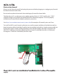
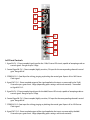
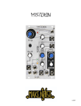
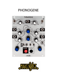
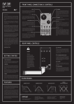
v 1.0
Limited WARRANTY:
Make Noise warrants this product to be free of defects in materials or construction for a period of one year
from the date of purchase (proof of purchase/invoice required).
Malfunction resulting from wrong power supply voltages, backwards or reversed eurorack bus board cable
connection, abuse of the product or any other causes determined by Make Noise to be the fault of the user
are not covered by this warranty, and normal service rates will apply.
During the warranty period, any defective products will be repaired or replaced, at the option of Make Noise,
on a return-to-Make Noise basis with the customer paying the transit cost to Make Noise. Please contact
[email protected] for Return To Manufacturer Authorization.
Make Noise implies and accepts no responsibility for harm to person or apparatus caused through operation
of this product.
Please contact [email protected] with any questions, needs & comments, otherwise...
go MAKE NOISE!
http://www.makenoisemusic.com
Electrocution hazard!
Always turn the Eurorack case off and unplug the power cord before plugging or un-plugging any Eurorack
bus board connection cable cable.
Do not touch any electrical terminals when attaching any Eurorack bus board cable.
The Make Noise LxD is an electronic music module requiring 30 mA of +12VDC and 30 mA of -12VDC
regulated voltages and a properly formatted distribution receptacle to operate. It must be properly
installed into a Eurorack format modular synthesizer system case.
Go to http://www.makenoisemusic.com/systems.shtml for examples of Eurorack Systems and Cases.
To install, find 4HP in your Eurorack synthesizer case, confirm proper installation of included eurorack bus
board connector cable on backside of module (see picture below), plug the bus board connector cable into
the Eurorack style bus board, minding the polarity so that the RED stripe on the cable is oriented to the
NEGATIVE 12 Volt line on both the module and the bus board. On the Make Noise 6U or 3U Busboard,
the negative 12 Volt line is indicated by the white stripe.
-12V
supply.
The LxD is a dual-response, two channel, direct-coupled, Low Pass Gate, which utilizes two vactrols in order
to provide simultaneous control over the Amplitude and Frequency content of an INput Signal. It is, in
essence, a VCFA (Voltage Controlled Filter Amplifier). Unlike the Optomix and some other dual-Low Pass
Gates, the LxD offers two different filter responses.
The top channel, CH. 1, offers a 12db/ Octave response that is mildly-resonant, while the bottom channel,
CH. 2, offers a 6db/ Octave that is non-resonant. The OUTput of CH. 1 is normalled to the INput of CH. 2.
Utilizing this normalization puts the two channels in series, which is similar to the classic VCF into VCA
arrangement made popular by many monosynths of the 1970’s.
Folks have often described the sound of a Low Pass Gate as “ringing.” While the LxD circuits are not actually
ringing, that term does describe many of the sounds possible when using a LPG, such as the LxD, in order to
process complex, harmonically-rich signals, generated through Frequency Modulation or Ring Modulation.
The LxD, being a vactrol-based circuit, will never have the speed or tight tolerances found in many other
VCA and VCF circuits. I would recommend that musicians desiring closely matched gain across
multiple channels of VCAs look elsewhere! If you seek to program extremely-short sounds, clicks, pops,
or ticks, the LxD is not the best choice.
What the LxD does offer is extremely low-noise and low-distortion in a smooth, natural-sounding circuit!
1
2
3
4
5
6
7
8
LxD Panel Controls
1. Signal IN CH. 1: Direct coupled signal input for the 12db/ Octave LPG circuit, capable of accepting audio or
control signals. Range of up to 15Vpp.
2. Control Signal IN CH. 1: Direct-coupled, highly sensitive, CV input for the corresponding channel’s vactrol
gate. Range 0V-8V.
3. STRIKE IN CH. 1: Gate INput for striking, pinging or plucking the vactrol gate. Expects 8V to 10V Gate or
Clock signal.
4. Signal OUT CH. 1: Direct-coupled output of the signal applied to the input, as processed by the 12db/
Octave low pass gate circuit. 10Vpp (depending upon settings and source material). Normalled
to Signal IN CH. 2.
5. Signal IN CH. 2: Direct-coupled signal input for the 6db/Octave LPG circuit, capable of accepting audio or
control signals. Range of up to 15Vpp.
6. Control Signal IN CH. 2: Direct-coupled, highly-sensitive, CV input for the corresponding channel’s vactrol
gate. Range 0V-8V.
7. STRIKE IN CH. 2: Gate input for striking, pinging or plucking the vactrol gate. Expects 8V to 10V Gate or
Clock signal.
8. Signal OUT CH. 2: Direct coupled output of the signal applied to the input, as processed by the 6db/
Octave low pass gate circuit. 10Vpp (depending upon settings and source material).
It’s a VCA, It’s a VCF...
The Low Pass Gate operates simultaneously in the amplitude and frequency domains. As the Control Signal
becomes more positive, the Amplitude of the Processed Signal increases: the low frequencies being more
quickly amplified than high frequencies. As the Control Signal become less positive, the Amplitude
decreases, with the high frequencies being attenuated much sooner than the low frequencies.
The net effect is that in fast, transient, modulation of the Processed Signal’s Amplitude, the low frequencies
will be more pronounced, lurking in the spectrum, while the high frequencies are eagerly diminished. A
fast/short envelope (Control Signal) of around +8V will provide a beautiful example of the LxD’s ability to
produce acoustic-like Attack and Decay transients. The processed signal will seem to ring-- not unlike a
struck drum, piano string or xylophone bar.
Two Unique Channels:
CH. 1:
As a VCF, CH. 1 is a mildly-resonant, Low Pass filter circuit, accentuating frequencies at and around the cutoff
frequency, which is determined by the Control Voltage level at the CH. 1 Control INput. As a VCA, CH. 1 has
a faster Attack and Decay response than CH. 2; however, it is still slower than the typical synthesizer VCF or
VCA. Like CH. 2, it has a smooth, natural-sounding response to modulation.
CH. 2:
As a VCF, CH. 2 is a very mild, non-resonant, Low Pass filter circuit, acting to gently reveal (or hide) the
sharper edges of a sound. This characteristic also adds to the “ringing” effect. As the amplitude of the
sound decays, there is a simultaneous loss in high frequency content that is similar to the natural loss of
energy in idio and membranophonic instruments. As a VCA, LxD CH. 2 has a moderate Attack response and
slow Decay response, meaning that it turns on quickly, but takes a while to shut off, yielding a smooth,
natural-sounding Decay to almost any sound processed dynamically.
:
Low Pass Gates such as the LxD are typically used to process audio signals. The LxD excels at processing
harmonically-rich sounds. Patch your audio signal (e.g. STO Variable Shape OUTput; DPO Square OUTput)
to the Signal INput of CH1. Next, patch a Control Voltage, such as an Envelope or LFO (e.g. CH. 1 or 4
MATHS; FUNCTION Non-Inverting OUTput with Cycle engaged), to the Control INput of CH. 1. Then, patch
the CH. 1 Signal OUT to your monitoring system and listen to the results. Experiment with changing the
Timbre of the Audio Signal you are processing (e.g. adjust the STO’s Variable Shape Control; patch DPO SAW
or FINAL OUTput instead of Square and adjust FREQuency) and the rate of the Control Signal patched to the
Control Signal INput. Now, patch a Clock signal (e.g. Wogglebug Clock OUT; MATHS/FUNCTION EOR or EOC
OUT) to the LxD CH. 1 STRIKE INput. Observe the sound. Remove the signal patched to LxD CH. 1 Control
Signal INput. Observe the sound. Setup this same patch, but instead using CH.2. Note the differences in
the result.
Now, try patching a Square Wave from your VCO (e.g. STO SUB OUTput; DPO Square OUTput) to LxD CH. 1
Signal INput. Patch an LFO (e.g. CH. 1 or 4 of MATHS; Non-Inverting OUTput from FUNCTION with CYCLE
engaged) to LxD CH. 1 Control INput. Patch a faster Square LFO or CLOCK signal (e.g. Wogglebug Clock
OUTput; MATHS or FUNCTION EOR or EOC OUTput) to LxD CH.2 STRIKE INput. Patch LxD CH. 2 Signal
OUTput to your monitoring system. Listen to the results of the classic VCF into VCA signal path: performed
here utilizing Low Pass Gates.
If utilizing the LxD in a sequencing patch, the STRIKE INput may act as an ACCENT parameter. Patch an
attenuated Envelope signal (e.g. from MATHS Channel 1 Signal OUTput with the Attenuvertor set to about 2
o’ clock) to the Control INput. Apply an Accent GATE/signal to the STRIKE INput. Steps where the Accent
Gate is Triggered will be LOUD.
Set up a Dynamic FM patch using one of the LxD’s CH. OUTputs to control the FM INDEX on the DPO. Rather
than applying an Envelope to CV the Control INput, just apply a Gate to the LxD’s Strike INput. This is a great
technique to add a burst of modulation and works with any signal source (e.g. LFO, Random Voltage, Noise,
etc) patched to the LxD’s CH. Signal INputs.
Use LxD to process Control Voltages:
Anywhere you desire a variable Modulation Index, patch the Modulation Source to be processed to either of
the LxD’s Signal Inputs, and patch the Control Signal that will determine the Modulation Index to the LxD’s
appropriate Control Signal INput. Finally, patch the LxD Signal OUTput from the corresponding channel to
your Modulation Destination.
Patch Concept:
The New Bongo
Patch Concept:
FM Pings:
Variation:
In order to dynamically control the FM Pings, first set up the patch as described above. Remove the cable
from the LxD CH. 1 OUTput and apply a slow Envelope from MATHS or FUNCTION (or any positively-moving
Control Voltage) to LxD’s CH. 2 Control INput. Finally, patch the LxD’s CH. 2 OUTput to the STO’s FM INput
(instead of the CH. 1 OUTput used before). This will further shape the Amplitude of the the FM Source as it
as being applied to the STO’s Linear FM INput.