1
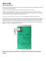
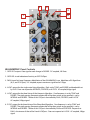
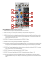
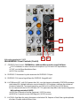
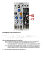
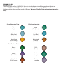
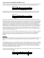
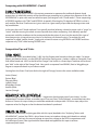
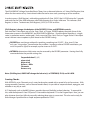
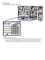
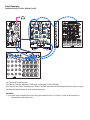
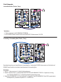
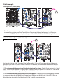
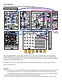
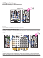
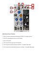
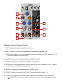
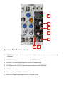
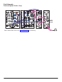
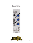
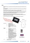
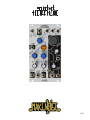
v. 2.
This device complies with Part 15 of the FCC Rules. Operation is subject to the following two
conditions: (1) this device may not cause harmful interference, and (2) this device must accept
any interference received, including interference that may cause undesired operation.
Changes / modifications not approved by the Make Noise Co. could void the user’s authority
to operate the equipment.
This equipment has been tested and found to comply with the limits for a Class A digital
device, pursuant to part 15 of the FCC Rules. These limits are designed to provide reasonable
protection against harmful interference when the equipment is operated in a commercial
environment. This equipment generates, uses, and can radiate radio frequency energy and, if
not installed and used in accordance with the instruction manual, may cause harmful
interference to radio communications.
makenoisemusic.com
Make Noise Co., 414 Haywood Road, Asheville, NC 28806
Limited WARRANTY:
Make Noise warrants this product to be free of defects in materials or construction for a period of one year
from the date of purchase (proof of purchase/invoice required).
Malfunction resulting from wrong power supply voltages, backwards or reversed eurorack bus board cable
connection, abuse of the product or any other causes determined by Make Noise to be the fault of the user
are not covered by this warranty, and normal service rates will apply.
During the warranty period, any defective products will be repaired or replaced, at the option of Make Noise,
on a return-to-Make Noise basis with the customer paying the transit cost to Make Noise. Please contact
[email protected] for Return To Manufacturer Authorization.
Make Noise implies and accepts no responsibility for harm to person or apparatus caused through operation
of this product.
Please contact [email protected] with any questions, needs & comments, otherwise...
go MAKE NOISE!
http://www.makenoisemusic.com
THANK YOU:
DSP Wizard:
Beta Analysts:
Test Subjects:
Spiritual Advisor:
Tom Erbe; www.soundhack.com
Devin Booze, Lee Coleman, Walker Farrell
James Cigler
Richard Devine
Electrocution hazard!
Always turn the Eurorack case off and unplug the power cord before plugging or un-plugging any Eurorack
bus board connection cable cable.
Do not touch any electrical terminals when attaching any Eurorack bus board cable.
The Make Noise tELHARMONIC is an electronic music module requiring 139mA of +12VDC and 10mA of
-12VDC regulated voltages and a properly formatted distribution receptacle to operate. It must be properly
installed into a Eurorack format modular synthesizer system case.
Go to http://www.makenoisemusic.com/systems.shtml for examples of Eurorack Systems and Cases.
To install, find 14HP in your Eurorack synthesizer case, confirm proper installation of included eurorack bus
board connector cable on backside of module (see picture below), plug the bus board connector cable into
the Eurorack style bus board, minding the polarity so that the RED stripe on the cable is oriented to the
NEGATIVE 12 Volt line on both the module and the bus board. On the Make Noise 6U or 3U Busboard, the
negative 12 Volt line is indicated by the white stripe.
-12V
Please refer to your case manufacturers’ specifications for location of the negative
supply.
The tELHARMONIC is a Multi-Voice, Multi-Algorithm synthesizer module coded by Tom Erbe and named for the
music hall where the first Telharmonium concerts were held. Telharmonic Hall is considered by some to be the
location of the first electronic music concerts. The Telharmonium was an early, pioneering electronic musical
instrument designed in 1897 by Thaddeus Cahill. It is believed to be the first additive synthesizer.
The Telharmonium weighed 200 tons and occupied the entire floor of “Telharmonic Hall” on 39th Street and
Broadway in New York City.
The Make Noise Soundhack tELhARMONIC module weighs less than 12 ounces and occupies 14hp in a Eurorack
synthesizer system.
The goal with the tELHARMONIC was to present three historically important pioneering electronic music tone
generation techniques less often implemented within the modular synthesizer: Additive Harmonic synthesis,
inspired by Thaddeus Cahill's original Telharmonium; Noise synthesis, inspired by James Tenney’s 1961, early
computer music piece "Analog 1: Noise Study;” Phase Modulation synthesis, inspired by early commercial digital
synthesis from the 1980's.
The tELHARMONIC could be thought of as having two sides. The left side has the voltage controlled music theory.
Through the use of TONIC, INTERVAL, DEGREE, and D-Gate, it is possible to create chord progressions, scales, and
playing styles using control voltages rather than playing manually or programming with MIDI. These parameters
influence the Noise, Harmonic, and Phase Mod Algorithms in a unified way. The right side of the tELHARMONIC
has the controls for sculpting the timbre. These are the CENTROID, FLUX and H-LOCK parameters. Each of these
parameters controls timbre of each of the Algorithms in a different way. This allows for complex sounds to be
created around a unified melodic structure and pattern. In other words, the Noise, Harmonic and Phase Mod
Algorithms, which are all available simultaneously at their respective outputs, were designed to be blended, mixed
and used together to emphasize a single musical motif.
To find the {Spiratone} within the tELHARMONIC:
With nothing patched to D-Gate, [HOLD] H-LOCK for 5 seconds. The sound will dramatically change and
you should now hear a Shepard Tone in the H or P Output(s). To return to tELHARMONIC, [HOLD] H-LOCK.
For more information, visit: http://www.makenoisemusic.com/Spiratone.html
3
4
5
1
6
2
tELHARMONIC Panel Controls
1. GATE OUT: outputs Gate signal at each change in DEGREE. DC-coupled, 10V Gate.
2. GATE LED: visual indication of activity at GATE OUTput.
3. FM IN: input for Linear Frequency Modulation of the tELHARMONIC core. Modulates all 3 Algorithms
(N, H, and P OUTputs). AC-coupled; expects maximum signal level of 15Vpp.
4. N OUT: output for the single-voice Noise Algorithm. Pitch set by TONIC and DEGREE and bandwidth set
by FLUX. Does not respond to INTERVAL, CENTROID, or H-LOCK. AC-coupled, 8Vpp signal.
5. H OUT: output for the three Voices of the Harmonic Algorithm. Core frequency is set by TONIC and
DEGREE. The pitch spacing (harmonic relationship of the three voices to one another) is set by
INTERVAL and DEGREE. Timbre of this OUTput is controlled by FLUX, CENTROID, and H-LOCK.
AC-coupled, 10Vpp signal.
6. P OUT: output for the three Voices of the Phase Mod Algorithm. Core frequency is set by TONIC and
DEGREE. The pitch spacing (harmonic relationship of the three voices to one another) is set by
INTERVAL and DEGREE. Timbre of this OUTput is controlled by FLUX and CENTROID. Response to
FLUX is the inverse of that of the N and H OUTputs. Does not respond to H-LOCK. AC-coupled, 10Vpp
signal.
7
8
12
9
13
10
11
14
15
16
tELHARMONIC Panel Controls (Cont’d)
7. TONIC Panel Control: adjusts the pitch of all Voices across 6 octaves.
8. TONIC CV IN: unity, 1V/ Octave pitch control INput. Not quantized. Range 0V to 6V.
9. INTERVAL Panel Control: sets the pitch spacing of the three Harmonic and Phase Mod Voices to form
Triads (with two Inversions), Fifths, Unison, or Octave relationships. Continuously variable, aside
from the two Inversions for Triads.
10. INTERVAL CV Attenuator: bi-polar attenuator for INTERVAL CV INput.
11. INTERVAL CV IN: control signal INput for INTERVAL. Range 0V to 5V.
12. COLOR STAFF: Toward the center of the tELHARMONIC there is a visual indicator that will change color
to display the state of INTERVAL and DEGREE, while pulsing to show the frequency of the TONIC.
13. DEGREE Panel Control: quantized note selection, relative to the pitch as defined by TONIC. Also deter
mines sonority of the TRIAD where applicable.
14. DEGREE CV Attenuator: bi-polar attenuator for DEGREE CV INput.
15. DEGREE CV IN: control signal INput for DEGREE. Quantized parameter. Range +/- 2V.
16. D-Gate IN: Gate INput for activation of DEGREE parameter. Normalled HIGH so that with nothing
patched, DEGREE is always active. Requires a Clock/Gate signal of at least 5V and width of at least
10ms.
17
18
19
With nothing patched to D-GATE
20
21
tELHARMONIC Panel Controls (Cont’d)
17. CENTROID Panel Control: CENTROID has a different effect on the N, H, and P OUTputs:
H OUT: modulates or selects harmonics for emphasis by FLUX and H-LOCK parameters.
P OUT: sets the Phase Modulation Ratio.
N OUT: has no effect.
18. CENTROID CV Attenuator: bi-polar attenuator for CENTROID CV INput.
19. CENTROID CV IN: control signal INput for CENTROID. Range 0V to 8V.
20. H-LOCK Button/LED: with FLUX greater than 10%, sets the Harmonic selected by CENTROID parameter
to be locked ON. Multiple Harmonics may be locked ON. LED brightness indicates the number of
Harmonics locked ON. To un-lock Harmonics, set FLUX to 0% or [HOLD] the H-LOCK Button
for one second until the H-LOCK LED fades OFF. This parameter only affects the Harmonic Algorithm.
With nothing patched to D-GATE:
[HOLD] for 5 seconds to find the {Spiratone}; [HOLD] to return.
[HOLD] for 2 seconds to enter {Shift Register}; [HOLD] to return.
21. H-LOCK IN: Gate INput for setting Harmonics to be locked ON. Requires a Clock/Gate signal amplitude
of at least 5V and a width of at least 10ms.
22
23
tELHARMONIC Panel Controls (Cont’d)
22. FLUX Combo Pot: unipolar Combo Knob. With nothing patched to FLUX CV INput, functions as a
standard panel control. When a control signal is patched to the FLUX CV INput, functions as an
attenuator for that signal as it is applied to the FLUX paramater.
FLUX has a different effect on the N, H, and P OUTputs:
-N OUT: increasing FLUX focuses the noise around the Fundamental, as set by TONIC and DEGREE.
-H OUT: At 0V (FLUX Fully CCW), all Harmonics are equally emphasized. Increasing FLUX
de-emphasizes all Harmonics surrounding the CENTROID, with the exception of those that are
currently locked by H-LOCK. This de-emphasis has the effect of emphasizing the CENTROID.
-P OUT: FLUX sets the Index of Phase Modulation-- the ratio is set by CENTROID. The response is the
inverse to that of the H and N OUTs. At 0V (FLUX Fully CCW), maximum Phase Modulation is
achieved. Gradually increasing this parameter decreases the Index of the Phase Modulation.
23. FLUX CV IN: unipolar control INput for FLUX. Range 0V to +8V.
Composing with tELHARMONIC 101
The left side of the module allows for patch programming chord progressions, scales, and melodies. It
consists of the TONIC, INTERVAL, DEGREE and D-GATE parameters and the visual indication of the Color
Staff. Although you will find great detail below about the inner workings in the next section, NO
KNOWLEDGE OF MUSIC THEORY IS REQUIRED TO COMPOSE WITH THE tELHARMONIC. These
parameters respond to control voltage just like anything else in your system.
Here are some quick pointers:
- You could think of Tonic as the main Pitch/FREQuency control, similar to the grey knob on a DPO or STO.
It is continuous (not Quantized) and responds 1V/Octave.
- Interval sets the spread of the Pitch/FREQuency between voices in the H and P Outputs. There are three
voices that can be set to Triad, Fifth, Unison, Octaves and anywhere in-between. Whatever Interval is
selected will be maintained when TONIC is manipulated. Unison (about 3 o’clock) has all three voices
set to the same note for behavior typical of a VCO.
- Degree adds or subtract up to two octaves from the base frequency set by Tonic. It has a Quantized
response and also tracks 1v/Octave when the DEGREE CV Attenuator is set Full CW. Because
DEGREE is a Quantized parameter, it has a “musically valid” response to any control voltage used.
- Whenever Degree changes values, a gate is generated and available for use at the GATE OUTput.
- The D-Gate Input operates as a Track & Hold for the DEGREE parameter. With nothing patched, D-Gate is
held HIGH and DEGREE will always be actively tracking the signal patched to the DEGREE CV IN. With
a clock, gate, pulse or trigger patched to D-Gate, the DEGREE parameter will only track the signal
patched to DEGREE CV IN while the D-Gate is held HIGH.
The FM IN is a fantastic way to introduce vibrato and pitch bend to a melody or progression. Patch any fast
control voltage or expression voltage to the FM IN to experiment with this technique.
For a more technical look at the musical applications of these parameters, read the section titled: "Composing with tELHARMONIC: Voltage-Controlled Music Theory."
Sculpting Timbre with tELHARMONIC: Moving CENTROID w/ FLUX
The tELHARMONIC has 3 independent and simultaneously available Algorithms, each with a unique timbre. Using
two control voltages and a Gate signal, full timbral animation of the tELHARMONIC is possible. Because the Noise,
Harmonic and Phase Mod algorithms all respond quite differently to these parameters, the results may be very
complex, and it is also possible to have some voices deeply modulated while other voices are not modulated at all.
The single voice Noise Algorithm, N-OUT, is inspired by the Music III patch that composer James Tenney wrote at
Bell Labs in 1961 for his first computer music piece, “Analog 1: Noise Study.” It consists of two band-limited noise
sidebands, which surround the frequency set by TONIC and DEGREE. FLUX controls the width of the sidebands,
which can go from extremely narrow (for a fluttering sinusoid) to full bandwidth. Using these two controls almost
any color of noise may be generated.
For the Harmonic Algorithm, H-OUT, each of the three voices is a 24-partial harmonic oscillator, using
high-resolution sine wave generators. The timbre is varied by the CENTROID and FLUX parameters, with
CENTROID setting the loudest of the 24 harmonics and FLUX setting the steepness of the gain roll-off around that
center harmonic. When FLUX is full CCW (0% modulation), the spectrum is flat and sweeping the CENTROID will
ripple the spectrum (like a string harmonic). When FLUX is increased, the harmonics surrounding the CENTROID
decrease in amplitude and the sound becomes more focused upon the center harmonic, which causes modulation
of the CENTROID to have a more dramatic effect.
When FLUX is not set to 0%, a Trigger or Gate in the H-LOCK INput or a [PRESS] of the H-LOCK button will cause the
partial that is currently selected by the CENTROID parameter to be locked ON at full amplitude even after
CENTROID changes. By sequencing CENTROID and Locking harmonics, many additive timbres can be found. To
clear all locked harmonics, [HOLD] the H-LOCK button for 1 second or set Flux to 0% via panel control or CV. This
parameter affects all three voices of the H-OUT, but does not affect the P or N OUTs.
Each voice of the Phase-Modulation Algorithm uses 3, phase-locked, sine wave oscillators, arranged as 2
Modulators and 1 Carrier. This algorithm will create a large number of harmonically-locked partials by reshaping
the Carrier (similar to wavefolding). The CENTROID controls the frequency ratio of the modulation, and therefore,
the brightness. The FLUX controls the Depth of Modulation, which determines the number of partials. When FLUX
is full CCW, this is the largest number of partials; when full CW, there is only 1-- a sine wave. The CENTROID
controls 2 adjacent harmonic modulation partials from 1 to 8. For example, when CENTROID is at 2.5, the
Modulator will be an even mix of harmonics 2 and 3.
Sculpting Timbre with tELHARMONIC: (cont’d)
FM IN :
Another method of exerting external influence upon the tELHARMONIC, allowing for even more complex timbres
by generating sidebands around all the harmonics created by each algorithm. Typically an analog SINE or
TRIANGLE waveform from a VCO such as the STO or DPO would be patched to this input. The high harmonic
content of the N, H and P OUTs on the tELHARMONIC means many sidebands will result from FM and so less
complex waveforms such as SINE and TRIANGLE will yield the most controllable results. Additionally an LPG or VCA
such as the Optomix could be patched in series (between the STO and tELHARMONIC) to achieve a dynamic FM
Index.
BLEnDING :
The Noise, Harmonic and Phase Mod voices were designed for fantastic spectral combination. The simplest way to
do this is using a mixer. However, it is highly useful to have each output patched to its own VCA or LPG (such as the
modDemix or Optomix) with a unique control signal to allow for the complete animation of dynamics and blending in creation of the final
HARMONICS AND TEMPERAMENT :
There are many settings of the right side of tELHARMONIC in which the upper harmonics dominate the
spectrum. Meanwhile, the left side of the tELHARMONIC can be used to force the fundamental pitches of
the three voices into Equal Temperament. These two planes of control create the possibility of using two
tuning systems simultaneously within the same instrument. In other words, the tELHARMONIC provides the
opportunity for smooth motion between Just and Equal Temperament.
ColoR STaFF :
Toward the center of the tELHARMONIC there is a visual indicator that will change color to indicate the
states of INTERVAL and DEGREE while pulsing to indicate the frequency of the TONIC (often this frequency is
high enough that the eye will not be able to discern). Warning: Color Staff is for entertainment purposes
only.
Second Inversion Triad:
First Inversion Triad:
Major:
(Aqua)
Major:
(Turquoise)
minor:
(Baby Blue)
minor:
(Sky Blue)
diminished:
(Light Orange)
diminished:
(Orange)
Root Position Triad:
Major:
(Green)
Fifth:
(Peach)
minor:
(Periwinkle)
Unison:
(Turquoise)
diminished:
(Dark Orange)
Octave:
(Lavender)
Composing with tELHARMONIC: Voltage-Controlled Music Theory
Recall from the previous section that the left side of the module allows for patch programming chord
progressions, scales, and melodies. It consists of the TONIC, INTERVAL, DEGREE, and D-GATE parameters and
the visual indication of the Color Staff.
TONIC
This parameter is similar to the Pitch control on a VCO, it responds continuously to a 1V/ Octave signal
across 6 octaves. TONIC will control all voices of the tELHARMONIC. This input is of course useful for
patching typical modular sequencing techniques, micro-tunings and modulations but it is also highly useful
for transposing progressions and melodies that are patch programmed using the DEGREE parameter (see
below). To achieve sequences or transpositions that are “in tune” you will either tune these TONIC changes
by ear or utilize a Quantized CV source, such as the QCV output from René.
The Tonic parameter sets the base frequency for the Interval and Degree parameters. In other words, the
Tonic sets the "key". Here is how a portion of the Tonic control looks swept clockwise with Interval set to
Root Triad and Degree set to a Major Triad. Note the Tonic control is continuous, thus the glissando
markings. Also, note that the sonority of the triad (Major in this example) does not change as it moves:
Tonic
DEGREE, D-GATE, AND GATE OUT
These parameters do not compare to any of the inputs and outputs typically found on a VCO module.
DEGREE is a quantized control that allows for ease in patch programming chord progressions and melodies
using just about any control voltage. It makes note selection relative to the pitch set by TONIC and
determines sonority of the TRIAD where applicable. DEGREE will control all Voices and Algorithms of the
tELHARMONIC and because it is a quantized parameter, any control voltage will result in a valid equal
temperament progression.
When INTERVAL is set to Unison, Fifth, Octave or any of their in-between spaces, DEGREE has twelve
possible values per octave, corresponding to the chromatic scale. When INTERVAL is set to TRIAD or a triad
inversion, DEGREE has seven possible values per octave, corresponding to the degrees of the diatonic scale:
I
ii
iii
IV
V
vi vii o
The pitch of “I”, and therefore the chosen “key,” is set by the TONIC parameter. Depending on the setting of
the DEGREE panel control, diatonic chord progressions can be easily be programmed in any mode
(including the Major and minor scales), with transposition/key change provided by TONIC.
Composing with tELHARMONIC: DEGREE (Cont’d)
Here is what a partial sweep of Degree looks like with Interval set to Root Position and Tonic set to D. Note
that the resulting triads' sonorities always match their scale positions in the key of D Major/b minor:
Degree (Triads)
When Interval is not set to Triad, Degree moves through the scale chromatically (12 possible values per
octave rather than the 7 Triads). For example here is part of a Degree sweep with Interval set to Fifth:
Degree (Fifths)
Using the D-GATE parameter it is possible to limit the amount of change in the DEGREE which will only
change when D-Gate is HIGH (keep in mind that D-GATE is normalled to +5V so that with nothing patched
to D-GATE, DEGREE will always be able to change). In this way the D-GATE allows the user to pick-off notes
and/ or chords from a continuous (or non-continuous) control voltage. It is a way of extracting melodies
and progressions from typically non-melodic sources such as LFOs, Envelopes, Expression Voltages or
Random Voltages. You could also use it to process Sequences where you do not want to utilize all notes in
the Sequence or to limit DEGREE changes to a tempo or clock within the system. By varying the Width of
the Gate signal patched to D-GATE to be narrow, you could grab single notes or chords from a control
voltage. By setting the width of the Gate signal patched to D-GATE to be wider, you could pick-off clusters
of notes or chords from a control source.
With each change in DEGREE a gate signal is generated and output at the GATE OUT. This gate is useful for
triggering events to coincide with a change in the Chord or Note generated by the tELHARMONIC, for
example an Envelope generator could be triggered to open a VCA or LPG each time the DEGREE is
changed.
INTERVAL :
This parameter controls the pitch spacing between the 3 Voices of the Harmonic and Phase Mod OUTs. The
Noise OUT is not controlled in any way by the INTERVAL parameter because the NOISE OUT is a single
voice.
The INTERVAL parameter starts with the TRIAD sonority at Full CCW. There are two Inversions of the TRIAD
as the INTERVAL parameter is increased. After the two Inversions, INTERVAL begins to continuously detune
and tune into Fifths followed by Unison and finally Octaves. There are many in-between tuning states
allowing for programming of complex, even dissonant, chords. The continuous nature of the detuning
and tuning makes INTERVAL modulate smoothly.
Here is what an F Major chord (as set by Degree and Tonic) looks like at all stages of the Interval parameter,
starting from full Counterclockwise:
Interval
Composing with tELHARMONIC: (Cont’d)
CHORD PROGrESSIons:
With Interval set to TRIAD, DEGREE is the easiest parameter to sequence for traditional diatonic chord
progressions in which the sonority of the chord changes according to its scale position. Because of this, the
tELHARMONIC is quite a bit more versatile than past synth engines with “Chord modes”. Clever sequencing
of DEGREE, together with TONIC and INTERVAL (especially if limiting the CV depth on INTERVAL so that it
only reaches the three Triad inversions) gives access to a great variety of possible chord progressions and
key modulations.
In the past, the use of “chord machines” has typically involved selecting a chord structure such as “major” or
“minor” and then moving the whole structure up and down when sequencing. Such blatantly-parallel
movement would be anathema to the contrapuntal chorale writers of yore, but the sound of this type of
chord progression is integral to many classics in the history of electronic music. To emulate this and
sequence so-called “techno chords”, simply pick a chord structure using INTERVAL and DEGREE and then
sequence only TONIC while leaving DEGREE static
Composition Tips and Tricks:
TrIAD MoDEs:
Set Interval to Triads (anywhere below 11:00). Use the Degree panel control to choose a mode. For Ionian
(Major) and Aeolian (minor), use the RGB LED to find the starting point. Aeolian is a Blue or Periwinkle Triad
that will be found one “click” to the left of the Orange Triad. Ionian is a Green/Aqua Triad that will be found
one “click” to the right of the Orange Triad. Now, patch a sequence from BRAINS, René or Wogglebug to
Degree to sequence chords in your chosen mode.
Starting from the Green Triad (one click to the right of Orange), here are the seven available modes:
Ionian (Green)
Dorian (Blue)
Phrygian (Blue)
Lydian (Green)
Mixolydian (Green)
Aeolian (Blue)
Locrian (Orange)
SEqUencIN g wITH AccIDEnTals:
Choose a mode as described in “Triad Modes”. Sequence a chord progression of your choice. Use the
unquantized CV output of René, or another row of Pressure Points Tuned Voltages, to modulate Interval to
Unison or Octaves on steps where you would like accidentals to be possible. For these steps, adjust the
sequence values for Degree so that the desired accidental is produced.
VIBRATO vIA FM IN :
In addition to the timbral sculpting possible with this input (detailed in the “Sculpting Timbre with
tELHARMONIC” section) the FM IN is also a fantastic way to introduce vibrato, pitch bend to a melody
or progression. Patch any fast control voltage or expression voltage to the FM IN to experiment with
this technique. Even a Gate signal could be attenuated and applied to this input to achieve
sequenced pitch bends.
3 -VO I CE sH I FT REG I STER:
The tELHARMONIC Voltage Controlled Music Theory has an alternate behavior: a 3-Voice {Shift Register} that
allows for the creation of any 3-note chord within the twelve-tone scale, spanning up to four ocataves.
In order to access {Shift Register}, with nothing patched to D-Gate, [HOLD] the H-LOCK button for 2 seconds
and watch for the Color Staff to become solid while listening for a single, solid tone. This indicates {Shift
Register} is Active. To deactivate {Shift Register}, [HOLD] H-LOCK to return.
{Shift Register} changes the behavior of the DEGREE, D-Gate, and INTERVAL controls.
Each time the D-Gate INput sees a Pulse, Gate, Clock, or Trigger, DEGREE updates the pitch of one of the
three voices present in the HARMONIC and PHASE MOD algorithms. (Since the Noise algorithm is a single
voice, its operation remains unchanged.) Each successive Pulse, Gate, Clock, or Trigger at the D-Gate INput
causes the next voice to update its pitch based on the DEGREE setting.
DEGREE does not change without first patching something into D-GATE. Also, since D-Gate
only sees “rising edges,” normalization has no effect. In order to achieve DEGREE modulation, you
must first patch a signal, for example, a pulse stream to D-GATE .
INTERVAL determines which notes may be accessed by the DEGREE parameter. Starting from fully
counterclockwise the possible settings are:
Suspended chord (1,4,5)
minor triad
Major triad
Octaves + fifths
Chromatic
Octaves only
Note: {Shift Register} DOES NOT change the behavior(s) of CENTROID, FLUX, and H-LOCK.
Creating Chords:
With INTERVAL set to Chromatic, any 3-note chord can be created with a spread of up to four octaves. With
a programmable Quantizer, such as the one found in René, it is possible to sequence chords, arpeggios, and
melodies in any key or scale.
A CV keyboard, such as the KMI QuNexus, provides the most flexibility in chord selection. To accomplish
this, send the keyboard’s Gate OUTput to D-Gate and the keyboard’s CV to the Degree INput. Now, you can
play whatever chord you’d like by manually selecting three notes in succession! This also works nicely for
chord changes layered within a simple sequence patched to TONIC.
Patch Example:
Drone with Sequential Harmonics (Thanks, Tony):
Variation:
1. Patch tELHARMONIC N OUT to FM IN.
2. With René CV OUT still patched to tELHARMONIC CENTROID CV IN, patch René QCV OUT to an analog VCO’s,
(such as STO or DPO) 1V/ Octave Input and tune the STO or DPO to one octave below the TONIC of
tELHARMONIC. Set René Q Page for Octaves only. Blend the analog VCO with H and P OUTS using
OPTOMIX’s AUX IN, mixing the tELHARMONIC’s H and P OUTs using the Ch.1 and Ch.2 Control knobs.
Patch Example:
Additive Presets (Thanks, Walker Farrell):
DUMMY
CABLE
DUMMY
CABLE
-Set Tonic and Degree to taste.
-Set René to Cartesian Mode on X-FUN page, and engage “Clock AND Mod.
Press the Pressure Points touchplate to "write in" the four harmonics of the selected René row. Each new press
will clear the locked Harmonics and write the new ones.
Variation:
1. Use a slow clock instead of Pressure Points gate, and Mult it to Y-CLK input. A new set of Harmonics is
introduced at each clock pulse.
Patch Example:
Interstellar Drone (Thanks, Tony):
Variations:
1. Patch a sequencer to tELHARMONIC DEGREE IN
2. Set CENTROID Panel Control Full CW and CENTROID CV Attenuvertor Full CCW
Ascending / Descending Run (Thanks, Tony):
If patched correctly, you should hear an Ascending Run. Setting the DEGREE Attenuvertor to 10 o'clock and
DEGREE Panel Control to 3 o'clock should produce a Descending Run.
Variations:
1. Set CH. 1 Attenuvertor to 1 o’clock for alternating run.
2. Patch a sequence that is synchronized to MATHS EOR to tELHARMONIC TONIC IN. Sequences running
at a multiple of MATHS CH. 1 will yield particularly interesting results.
3. Patch the tELHARMONIC H-OUT to Optomix Ch.1 Signal IN. Patch tELHARMONIC Gate OUT to generate an
Envelope that is patched to Optomix Ch.1 CONTROL IN.
Patch Example:
Intelligent Bass (Thanks, Tony):
Variation:
-Instead of using the Pressure Points Tuned Voltage Output, use a Keyboard or Sequencer’s CV Output to
control DEGREE. Patch the Keyboard/Sequencer Gate OUT to MATHS (or FUNCTION) Trigger INput. Solar Wind Chimes (Thanks, Walker Farrell):
Click here to watch on YouTube
Set Interval to Unison (~3:00, Turquoise Color Staff), and adjust Tonic and Degree to set desired fundamental.
With each cycle of MATHS, several random Harmonics will be locked, which are cleared at the end of the cycle
Variations:
1. This variation adds the wooshing of wind to the ringing of the chimes: Patch H Out to Optomix Ch.1 Signal
INput. Patch N Out to Optomix Ch.2 Signal INput. Mult MATHS Unity to Optomix Ch2 Control CV In. Set Control
knobs to taste, while monitoring from the Optomix’s SUM OUT.
2. This variation adds semi-predictability to the chime pattern: Doublecheck that the Wogglebug clock rate
is somewhat higher than the MATHS cycle rate (at least 4 WB clocks per MATHS cycle). Mult MATHS Unity to
Wogglebug Ego Input, adjust Ego/Id Balance full CCW, gradually increasing to taste.
Patch Example:
Chordal Accompaniment Variations (Thanks, Walker Farrell):
Click here to watch on YouTube
(Adjust to Taste)
Adjust the telHARMONIC’s Tonic Panel Control until it sounds in tune with the DPO’s VCO B Frequency.
Set the DEGREE Panel Control full CCW, Interval to a Triad. Adjust the DPO’s Fold Panel Control full CCW
with the Shape and Angle Controls to taste. Set the DEGREE input attenuator to taste. Adjust or modulate
Centroid, Flux and/or H-LOCK to taste.
Each press of the Pressure Points will select a new chord progression. Sparser Y-Gate settings will yield
sparser accompaniment.
Variation:
1. Run QCV through a VCA prior to DEGREE to place chord progression range under voltage control (should still
mult the unaltered QCV to DPO). For example, set DEGREE Panel Control to 12:00, and patch QCV to
the modDemix Channel 1 Input, modulated with a bipolar control signal. Patch Ch.1 Output to DEGREE.
2. Use René CV out to modulate MATHS Fall time for different chord lengths.
3. Patch a slower clock instead of the Pressure Points Gate Output in order to change patterns automatically.
{Shift Register} Patch Examples:
Broken and Fixed Arpeggios (Thanks, Walker Farrell):
{Shift Register} = Active
Variation:
Sequence TONIC and INTERVAL to achieve chord progressions.
Clusters and Frames (Thanks, Walker Farrell):
Create any 3-voice pattern in any scale by altering the Snake pattern, Location panel controls, and {Q} Page
settings.
{Shift Register} = Active
(Adjust to Taste)
Variation:
Sequence CENTROID with René's unquantized CV output and H-LOCK with G-Y, while also shifting Snake
patterns (don't forget to clear H-LOCK periodically-- either manually or by bringing FLUX Full CCW with CV).
SpirA tone
v. 1.
Spiratone Overview:
The {Spiratone} is a form of Shepard Tone generator. It is a sonic barber pole that creates the auditory
illusion of a tone that continually ascends or descends in pitch, yet ultimately seems to get no higher or
lower. It was inspired by Jean-Claude Risset’s "Computer Suite from Little Boy: Fall," 1968 and James
Tenney’s "For Ann (rising)," 1969.
It occupies the same space as the tELHARMONIC.
To find the {Spiratone} on the tELHARMONIC:
With nothing patched to D-Gate, [HOLD] H-LOCK for 5 seconds. The sound will dramatically change and
you should now hear a Shepard Tone in the H or P Output(s).
3
4
5
1
6
2
{Spiratone} Panel Controls
1. GATE OUT: outputs Gate signal at each change in DEGREE. DC-coupled, 10V Gate.
2. GATE LED: visual indication of activity at GATE OUTput.
3. FM IN: NOT UTILIZED
4. N OUT: output for the single-voice Noise Algorithm.
5. H OUT: Output for half of the Spiratone’s oscillators. AC-coupled, 10Vpp signal.
6. P OUT: Output for the other half of the Spiratone’s oscillators. AC-coupled, 10Vpp signal.
7
8
9
10
11
12
13
14
15
{Spiratone} Panel Controls (Cont’d)
7. TONIC Panel Control: adjusts the pitch of all oscillators.
8. TONIC CV IN: unity, 1V/ Octave pitch control INput. Not quantized. Range 0V to 6V.
9. INTERVAL Panel Control: Sets internal modulation speed, no modulation at NOON, modulates up CW
from NOON, and down CCW from NOON.
10. INTERVAL CV Attenuator: bi-polar attenuator for INTERVAL CV INput.
11. INTERVAL CV IN: control signal INput for INTERVAL. Range 0V to 5V.
12. DEGREE Panel Control: quantized note selection, relative to the pitch as defined by TONIC. Also deter
mines sonority of the TRIAD where applicable.
13. DEGREE CV Attenuator: bi-polar attenuator for DEGREE CV INput.
14. DEGREE CV IN: control signal INput for DEGREE. Quantized parameter. Range +/- 2V.
15. D-Gate IN: Gate INput for activation of DEGREE parameter. Normalled HIGH so that with nothing
patched, DEGREE is always active. Requires a Clock/Gate signal of at least 5V and width of at least
10ms.
17
22
23
18
19
20
21
{Spiratone} Panel Controls (Cont’d)
17. CENTROID Panel Control: Sets the spacing of the oscillators from one octave to a very narrow pitch
difference.
18. CENTROID CV Attenuator: bi-polar attenuator for CENTROID CV INput.
19. CENTROID CV IN: control signal INput for CENTROID. Range 0V to 8V.
20. H-LOCK Button/ LED: [HOLD] to exit {Spiratone} and return to {tELHARMONIC}.
21. H-LOCK IN: Not used
22. FLUX: Sets the level of Random Pitch Modulation
23. FLUX CV IN: unipolar control INput for FLUX. Range 0V to +8V.
Patch Example:
Sentient Bottle Rocket (Thanks, Tony!):
Press any pad on the Pressure Points to ignite the Sentient Bottle Rocket.
Patch Example:
Artificial De-Celleration (Thanks, Tony!):
Briefly turn on MATHS Ch. 1 Cycling and wait for Ch. 4 to be triggered via EOR. At which point, press the Ch.1
CYCLE Button again in order to disengage cycling, allowing the trigger loop to continue indefinitely.
Patch Example:
Stereo Spiralgraph (Thanks, Tony!):
RATE AND
INTERVAL
CONTROL
MASTER
VOLUME
CONTROL
Note: Stereo Patch. Must use a stereo/TRS cable for monitoring.
TRS