1
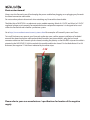
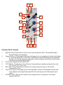
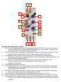
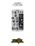
Function
v2.0
Limited WARRANTY:
Make Noise warrants this product to be free of defects in materials or construction for a period of one year
from the date of purchase (proof of purchase/invoice required).
Malfunction resulting from wrong power supply voltages, backwards or reversed eurorack bus board cable
connection, abuse of the product or any other causes determined by Make Noise to be the fault of the user
are not covered by this warranty, and normal service rates will apply.
During the warranty period, any defective products will be repaired or replaced, at the option of Make Noise,
on a return-to-Make Noise basis with the customer paying the transit cost to Make Noise. Please contact
[email protected] for Return To Manufacturer Authorization.
Make Noise implies and accepts no responsibility for harm to person or apparatus caused through operation
of this product.
Please contact [email protected] with any questions, needs & comments, otherwise...
go MAKE NOISE!
http://www.makenoisemusic.com
THANK YOU
Beta Analyst: Peter Speer
Test Subjects: James Cigler
Spiritual Advisor: Richard Devine
Special Thanx to MATHS!
Electrocution hazard!
Always turn the Eurorack case off and unplug the power cord before plugging or un-plugging any Eurorack
bus board connection cable cable.
Do not touch any electrical terminals when attaching any Eurorack bus board cable.
The Make Noise FUNCTION is an electronic music module requiring 30mA of +12VDC and 30 mA of -12VDC
regulated voltages and a properly formatted distribution receptacle to operate. It is designed to be used
within the Eurorack format modular synthesizer system.
Go to http://www.makenoisemusic.com/systems.shtml for examples of Eurorack Systems and Cases.
To install, find necessary space in your Eurorack synthesizer case, confirm proper installation of included
eurorack bus board connector cable on backside of module (see picture below), plug the bus board
connector cable into the Eurorack style bus board, minding the polarity so that the RED stripe on the cable is
oriented to the NEGATIVE 12 Volt line on both the module and the bus board. On the Make Noise 6U or 3U
Busboard, the negative 12 Volt line is indicated by the white stripe.
-12V
Please refer to your case manufacturers’ specifications for location of the negative
supply.
1
2
3
4
5
6
7
8
10
9
12
11
13
14
15
16
17
Function Panel Controls
1.
2.
3.
4.
5.
6.
7.
Signal IN: Direct Coupled input to circuit. Use for Lag, Portamento, S&H, T&H and ASR (Attack
Sustain Release type envelopes).
Trigger IN: Gate or Pulse applied to this input will trigger the circuit regardless of activity at the Signal
IN. The result being a 0V to 8V function, aka Envelope, whose characteristics are defined by
the Rise, Fall, and Vari-Response parameters. Use for Envelope, Pulse Delay, Clock Division,
LFO Reset (only during Falling portion).
CYCLE LED: Indicates CYCLE ON or OFF.
CYCLE Button: Causes the circuit to self-cycle, thus generating a repeating voltage function, aka
LFO. Use for LFO, Clock, VCO.
Rise Panel Control: Sets the time it takes for the voltage function to ramp up. CW rotation
increases Rise Time.
Rise CV IN: Linear control signal input for Rise parameter. Positive Control signals increase Rise
Time. Negative control signals decrease Rise Time with respect to the Rise panel control
setting.
Fall Panel Control: Sets the time it takes for the voltage function to ramp down. CW rotation
increases Fall Time.
1
2
3
4
5
6
7
8
10
9
12
11
13
14
15
Function Panel Controls (cont’d)
8.
9.
10.
11.
12.
13.
14.
15.
16.
17.
16
17
Both CV IN: Bi-Polar Exponential control signal input for entire FUNCTION. Contrary to the Rise and
Fall CV IN, BOTH has an Exponential response and Positive control signals decrease total
time while Negative control signals increase total time.
Fall CV IN: Linear control signal input for Fall parameter. Positive control signals increase Fall Time.
Negative control signals decrease Fall Time with respect to the Fall panel control.
Vari-Response Panel Control: Sets the response curve of the voltage function. Response is
continuously variable from Logarithmic through Linear to Exponential to Hyper-Exponential. The
Tick mark shows the Linear setting.
HANG IN: Gate or Pulse applied to this input will stop the circuit dead in its tracks. Use for
programming S&H, Track and Hold, Stepped Functions, Stepped LFOs,
synchronized Functions.
LED indicates activity within the circuit.
Non- Inverted Signal OUT: Non-inverted signal from the FUNCTION circuit. Buffered and capable of
accurately driving a 4 way multiple. 8V peak to peak when Cycling. Otherwise this output will
follow the amplitude of the input.
EOR/ EOC LED: Indicates the states of the EOR and EOC outputs. When RED EOC is HIGH and
EOR is LOW. When Green EOR is HIGH and EOC is LOW.
End Of Rise OUT: Goes high at the end of the Rise portion of the function. 0V or 10V.
End Of Cycle OUT: Goes high at the end of the Cycle (or Falling) portion of the function. 0V or 10V.
Inverted Signal OUT: Inverted signal from the FUNCTION circuit. Buffered and capable of accurately
driving a 4 way multiple. 8V peak to peak when Cycling. Otherwise this output mirrors the input
amplitude.
Overview:
FUNCTION is part of the MATHS family of control voltage utility modules. It is a small analog computer
designed for musical purposes. Amongst other things, the Function will allow you to:
1. Generate a variety of linear, logarithmic, or exponential triggered or continuous functions
2. Generate discrete time functions
3. Integrate an incoming signal
4. Invert an incoming signal
5. Generate analog signals from digital information (Gate/ Clock)
6. Generate digital information (Gate/ Clock) from analog signals
7. Delay digital (Gate/ Clock) information
If the above list reads like science rather than music, here is the translation:
1. Voltage Controlled Envelope or LFO
2. Stepped voltages like Sample and Hold, Track and Hold, Staircase LFO
3. Apply Lag, Slew or Portamento to control voltages
4. Modulate backwards!
5. Musical Events such as Ramping up or Down in Tempo, on command
6. Initiating Musical events upon sensing motion in the system
7. Musical note division and/ or Flam
Indeed the FUNCTION is a direct descendent of MATHS, sharing the same core circuit, complete with some
evolutions:
1.
Since most Make Noise modules have attenuators on the CV inputs, the scaling/ inversion feature has
been replaced with dedicated Non-Inverted/ Inverted outputs. This is useful as you could have
the same signal modulating two different destinations in opposition.
2.
As FUNCTION is single channel design, we included both EOR and EOC. There is interesting things
you could do with these outputs such as flams (see patch tips). Much like CH 1 and 4 on the
MATHS, multiple FUNCTIONs can also be used to program complex functions using EOR and
EOC.
3.
The evolution in the circuit is the HANG input. On Gate HIGH at the HANG IN, the FUNCTION is
stopped dead in its tracks. With HANG you can program Stepped LFOs, Synchronized
Functions (using multiple of clock), S&H, Track & Hold, Clock Run/ Stop (using EOR or EOC out
for Clock) and more.
Tips & Tricks
-Longer cycles will be achieved with more Logarithmic response curves. The fastest, sharpest
functions will be achieved with extreme exponential response curves.
-Adjustment to the response curve will affect Rise and Fall Times.
-To achieve longer or shorter Rise and Fall Times than available from Panel Controls, apply a voltage
offset to the Control Signal Inputs.
-Extremely long cycles may be achieved by setting Rise and Fall to about 50% and patching a slow
clock to HANG.
-It helps to have control over the WIDTH of the gate/ clock applied to the HANG input, so another
MATHS (or other modules with Gate/ clock width control such as Pro Modular CLOQ) will be
very handy.
-Use the Inverted Signal OUT where you require reversed modulation but do not have means for
inversion at the CV destination (no attenuvertor).
-Feeding the Inverted Signal OUT back into the FUNCTION at any of the CV inputs is highly useful
(see patch tips).
Patch Ideas Analog/ Control Voltages:
Voltage Controlled Transient Generator (Attack/ Decay Envelope) A pulse or gate applied to the Trigger IN
starts the transient function, which rises from 0V to 8V at a rate determined by the Rise parameter, then
Falls from 8V to 0V at a rate determined by the Fall parameter. This function is re-trigger-able during the
falling portion. Rise and Fall are independently voltage controllable, with response as set by the
Vari-Response panel Control.
Voltage Controlled Sustained Function Generator (A/S/R Envelope)
A gate applied to the Signal IN starts the function which rises from 0V to the level of the applied Gate at a
rate determined by the Rise parameter. The function Sustains at that level until the Gate signal ends, then
Falls from that level to 0V at a rate determined by the Fall parameter. Rise and Fall are independently
voltage controllable, with variable response as set by the Vari-Response panel Control.
Typical Voltage Controlled Triangle Function (LFO)
Push Cycle Button. Cycle LED lights. Set Rise and Fall Panel Control to NOON. Apply desired modulation to
BOTH CV input. Setting Rise and Fall parameters further CW will provide longer cycles. Setting these
parameters further CCW will provide short cycles, up to audio rate. The shape of the resulting function may
be varied from LOG to LINEAR to EXPO using the Vari-Response panel control.
Typical Voltage Controlled Ramp Function (LFO)
As above, only the Rise parameter is set FULL CCW, Fall parameter is set to at least NOON. Fall parameter
as well as the BOTH control voltage IN determines the rate.
VC LAG/ Slew Processor/ Portamento
A signal applied to the Signal IN is slewed according to the RISE and FALL parameters. Variable response
from Log through Linear to Exponential, as set by the Vari-Response panel Control. Portamento is
traditionally LOG response. The inverse of the resulting function is available at the Inverted Signal OUT.
Independent Contours (Expo Rise w/ Log Fall and vice versa) Set Vari-Response to Full CCW for Log
response. Patch Inverted OUT to Rise CV IN. This yields Expo Rise with Log Fall for most any function. If
Inverted out is patched to Fall CV IN, Log Rise w/ Expo Fall is achieved. By setting Vari-Response to Linear,
combinations of Linear and Expo or Log are possible.
Envelope Follower Apply Signal to be followed to Signal IN
Set Rise to NOON. Set and or modulate FALL Time to achieve different amounts of Smoothing. Take output
from Non-Inverted Signal OUT. Increasing the Fall Time to beyond 70% will result in the Peaks being held for
long periods of time. EOR and EOC will also indicate activity at the Signal IN. A variation on this patch has
EOR patched to the HANG IN. The Peak is detected and held until user resets (by removing patch cable
from HANG IN).
Multiplication (VCA)
Apply positive going Control Signal to be multiplied to Signal IN. Set Rise and Fall to full CCW. Apply positive
going Control Signal (multiplier) to BOTH Control IN. Take output from Signal OUT.
Patch Ideas Digital/ Gates/ Clocking:
Typical Voltage Controlled Pulse (Clock, LFO)
Same as Voltage Controlled Triangle Function, only the output is taken from EOC or EOR. Using EOR, the
RISE parameter will more effectively adjust frequency, and FALL parameter will adjust pulse width. Using
EOC, the opposite is true: where Rise more effectively adjusts Width and Fall adjust frequency. All
adjustments to Rise and Fall parameters will affect frequency. HANG input will act as Start/ Stop control with
the Clock STOPPING when you send a Gate HIGH to HANG. FLIP-FLOP (1-Bit Memory) In this patch,
Trigger IN acts as the “Set” input, and BOTH Control IN acts as the “Reset” input. Apply Reset signal to
BOTH Control IN. Apply Gate or logic signal to Trigger IN. Set Rise to Full CCW, Fall to Full CW,
Vari-Response to Linear. Take “Q” output from EOR, “NOT Q” from the EOC OUT. This patch has a memory
limit of about 3 minutes, after which it forgets the one thing you told it to remember.
Voltage Controlled Pulse Delay Processor
Apply Trigger or Gate to Trigger IN. Take output from End Of Rise. RISE parameter will set the delay and
Fall parameter will adjust width of the resulting delayed pulse.
Voltage Controlled Flam
Apply Trigger, Clock or Gate to Trigger IN. Set Rise for Full CCW. Fall for at least 50%. Take output 1 from
End Of Rise, and patch to Optomix CH. 1 Strike IN. Take output 2, the Flam, from EOC, patch to Optomix
CH. 2 Strike IN. Apply Signal(s) to be Flammed at Optomix Signal IN 1 and 2. Monitor SUM out. Flam control
is performed with the Fall parameter.
Voltage Controlled Clock Divider
Clock signal applied to Trigger IN is processed by a divisor as set by Rise parameter. Increasing Rise sets
divisor higher, resulting in larger divisions. Fall time adjusts the width of the resulting clock. If the Width is
adjusted to be greater than the total time of the division the output will remain “high.” Take output from EOR
or EOC.
Sample & Hold
Signal to be processed is patched to Signal IN. Clock signal patched to HANG IN. Clock signal must be wide
in order to achieve S&H. In other words, the clock should be HIGH most of the time, going low for only a
short time. An example of this type of clock signal would be to use another FUNCTION (or a channel of a
MATHS). Use the EOC, with Fall set to Full CCW and setting the Rise to determine the rate. The Rise and
Fall parameters determine the range of possible values.
Track & Hold
Signal to be processed is patched to Signal IN. Clock or Gate signal patched to HANG IN. Signal will pass to
the Signal OUT with the Rise and Fall parameters determining the slew rate. When the HANG IN goes
HIGH, the Signal OUT will be held at the current voltage, until the HANG IN goes Low.
Staircase Function (Triggered or Continuous)
Set up for Typical Voltage Controlled LFO (see above). Patch clock signal to HANG IN. Clock should be at
higher frequency then that of the function.