1
Using FlashRunner FR03TXI0 to Program UCD3020/3028/3040 and UCD3138
SLUA654 - August 2012
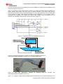
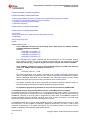
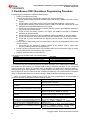
Figure 9. The target device can be biased directly from the PMBUS line coming from the FlashRunner ISP
connector (jumper J2 in Figure 9-1).
NOTE: It is necessary to insert a high-frequency capacitor, CHF between the PMBUS_DATA and GND line to
support 400kHz data transfer. The exact value of capacitor depends on the cable length and the
programming environment. 47pF is a good starting point for a 20cm (approximately 8” cable). A higher value
may be needed for longer cable lengths and different board configurations. As an example, Table 1
summarizes the capacitance value needed with different cable lengths in tests conducted at TI. This
capacitor can be installed close to the ISP connector as shown in Figure 10.
1
2
3
5
4
6
7
9
8
10
PMBUS
Connector
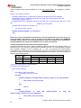
Figure 9-1. UCD3138CC64EVM-030 PMBUS Connector (J1)
PMBUS_CLK
PMBUS Connector J1
(UCD3138CC64EVM-030)
3.3VD
9
7
5
3
1
10
8
6
4
2
PMBUS_DATA
DGND
CHF
DIO2
8
7
15
6
14
VPROG0
5
13
4
12
11
GND
DIO1
3
2
10
1
9
ISP Connector
(Flashrunner FR03)
Figure 9-2. Cable (with high-frequency capacitor) for interfacing FR03 ISP Connector to
UCD3138CC64EVM-030 PMBUS Connector (J1) for in system programming
CHF
To PMBUS
Connector
To FR03 ISP Connector
Figure 9-3. Cable (with high-frequency capacitor)
UCD3138CC64EVM-030 PMBUS Connector (J1)
for
interfacing
FR03
ISP
connector
with
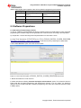
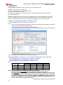
Table 1: CHF capacitor needed between PMBUS_DATA and GND lines for successful programming with
Copyright © 2012, Texas Instruments Incorporated
7