1
Using FlashRunner FR03TXI0 to Program UCD3020/3028/3040 and UCD3138
SLUA654 - August 2012
Using FlashRunnerTM FR03TXI0
for Standalone Programming
of
UCD3020/UCD3028/UCD3040 & UCD3138
Digital Power Controllers
August 2012
SLUA654
Copyright © 2012, Texas Instruments Incorporated
1
Using FlashRunner FR03TXI0 to Program UCD3020/3028/3040 and UCD3138
SLUA654 - August 2012
Table of Contents:
1.0 Introduction to FlashRunner FR03TXI0…………………………………..……………..4
2.0 System Set-Up for Successful Programming………………………….……………..…6
2.2 Hardware Preparations………………………………………………………………..6
2.3 Software Preparations…………………………………………………………………8
3.0 FlashRunner FR03 Standalone Programming Procedure…………………………...21
4.0 Source Code Requirements for Successful Programming………………………..…22
5.0 UCD3xxx Device Programming Time using FlashRunner FR03……………………25
6.0 References………………………………………………………………………………..25
Copyright © 2012, Texas Instruments Incorporated
2
Using FlashRunner FR03TXI0 to Program UCD3020/3028/3040 and UCD3138
SLUA654 - August 2012
Scope of this Document
This document from Texas Instruments provides step by step information about Hardware and Software
setup of FlashRunner FR03TXI0 required for standalone programming UCD30xx and UCD3138 digital
controllers.
Additional documentation available from SMH Technologies (www.smh-tech.com) regarding generic
FlashRunner FR03 topics include:
o FlashRunner FR03 – User’s Manual
o FlashRunner FR03 – Programmer’s Manual
Additional documentation available from SMH Technologies (www.smh-tech.com) regarding programming
UCD3020/3028/3040 & UCD3138 controllers using FlashRunner FR03:
o AN00153: Interfacing FlashRunner with TI UCD30XX Devices (DC10496.pdf)
Additional documentation available from Texas Instruments regarding UCD30xx and UCD3138 controllers:
o UCD3040/20/28 Device Datasheet, Literature # - SLU868
o UCD30xx Flash Application Note
o
o
UCD3138 Device Datasheet, Literature # - SLUSAP2
UCD3138 ARM and Digital System Programmer’s Manual
For the most up to date product specifications please visit www.ti.com.
Copyright © 2012, Texas Instruments Incorporated
3
Using FlashRunner FR03TXI0 to Program UCD3020/3028/3040 and UCD3138
SLUA654 - August 2012
1. Introduction
1.1 FlashRunner FR03 Overview
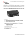
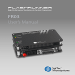
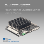
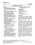
FlashRunner FR03 is a high-performance, standalone In-System Programmer from SMH Technologies
specific for Flash-based microcontrollers and serial memories. FlashRunner FR03 is targeted at production
environments, easily interfaces to a programming system or Automatic Test Equipment (ATE) and can work
either in full standalone mode or controlled by a host system.
FlashRunner FR03TXI0 is capable of programming Texas Instruments digital controller devices UCD3020,
UCD3028, UCD3040 and UCD3138. PMBUS protocol (at 400kHz operating frequency) is used to program
these devices.
Figure 1: FlashRunner FR03 from SMH Technologies
1.2 Features
Key attributes of FlashRunner FR03 include:
▪
Standalone operation with Start button (projects and code images stored on a memory card)
▪
Controllable by any host system via RS-232, also can be integrated with ATE
▪
Supports ISP (in-system programming) protocols
▪
LED indicators for Power, Instrument Status & Programming Status (Busy/pass/Fail)
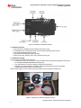
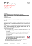
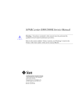
1.2.1 Hardware Features
• ISP connector with I/O ports for communication with target device that is to be programmed
- Five digital I/O lines
- Two digital I/O or analog output lines
- One programmable output voltage (0 to 5.5V, 0.5A)
- One programmable clock output
• Secure Digital memory card (up to 2 GB)
• One command input button (START)
• Three programming status LED indicators (FAIL, PASS, BUSY)
• RS-232 channel communication with host system
• 7.5V DC power supply input
Copyright © 2012, Texas Instruments Incorporated
4
Using FlashRunner FR03TXI0 to Program UCD3020/3028/3040 and UCD3138
SLUA654 - August 2012
Figure 2: FlashRunner Hardware Features
1.2.2 Software Features
• Fully autonomous standalone mode (based on SD memory card)
• Controllable by any host system through a terminal utility and simple ASCII protocol.
• One hardware-selectable project (script)
• Unlimited software-selectable projects (scripts)
• Erase, blank check, program, read, verify, oscillator trimming, etc.
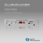
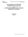
1.2.3 FR03TXI0 Package
Key items in the FR03TXI0 package include:
• FlashRunner FR03 unit, including SD card pre-installed with the programming algorithm and licences
for UCD3020/UCD3028/UCD3040/UCD3138 devices
• 9-pin Serial cable for connection between FlashRunner and host PC
• FlashRunner “System Software” CD-ROM, containing the FlashRunner Control Panel utility
installation files and FlashRunner documentation
AC/DC Power Supply (7.5V DC output) must be provided by user to power up FlashRunner.
Figure 3: FlashRunner FR03TXI0 package contents
Copyright © 2012, Texas Instruments Incorporated
5
Using FlashRunner FR03TXI0 to Program UCD3020/3028/3040 and UCD3138
SLUA654 - August 2012
2. System Set-Up for Successful Programming
2.1 Overview
The following steps are necessary in order to use FlashRunner FR03 to achieve standalone programming of
the UCD3xxx devices:
1. Hardware Preparations
a) Develop hardware interface between FR03 and Target board with the UCD3xxx device
2. Software preparations
a) Generate Image file for programming the target device
b) Generate script file SCRIPT0.FRS for standalone operation
c) Install Image file and script files in SD card using FlashRunner FR03 Utility
2.2 Hardware Preparations
A Connector is necessary to interface between the target UCD3xxx device and FR03. UCD3xxx devices are
programmed using PMBUS/I2C communication interface. It is possible to power the UCD3xxx device using
the VDD/GND connectors available from FR03.
The UCD3xxx device I/O ports involved in programming are as follows:
PMBUS_CLK : PMBUS Clock frequency
PMBUS_DATA : PMBUS Data line
V33A & V33D : Device Bias supply
DGND & AGND : Device ground
These UCD3xxx I/O lines must be connected to the FlashRunner’s “ISP” connector according to Figure 8.
Flashrunner FR03
ISP Connector Pins
V33D, V33A
DGND, AGND
VPROG0
GND
UCD3xxx
PMBUS_CLK
DIO1
PMBUS_DATA
DIO2
(a): UCD3xxx & FlashRunner FR03 ISP connector pins involved in programming
(b) FlashRunner FR03 ISP connector pins involved in programming (to be interfaced with UCD3xxx target device)
Figure 8. Hardware Interface requirement between UCD3xxx target device and FR03 ISP connector
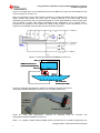
For example, if the target device is located on the UCD3138CC64EVM-030 EVM from Texas Instruments
(http://www.ti.com/tool/ucd3138cc64evm-030), then a connector cable must be prepared between the
FlashRunner ISP connector and the PMBUS connector J1 in UCD3138CC64-030 EVM. This is illustrated in
Copyright © 2012, Texas Instruments Incorporated
6
Using FlashRunner FR03TXI0 to Program UCD3020/3028/3040 and UCD3138
SLUA654 - August 2012
Figure 9. The target device can be biased directly from the PMBUS line coming from the FlashRunner ISP
connector (jumper J2 in Figure 9-1).
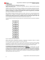
NOTE: It is necessary to insert a high-frequency capacitor, CHF between the PMBUS_DATA and GND line to
support 400kHz data transfer. The exact value of capacitor depends on the cable length and the
programming environment. 47pF is a good starting point for a 20cm (approximately 8” cable). A higher value
may be needed for longer cable lengths and different board configurations. As an example, Table 1
summarizes the capacitance value needed with different cable lengths in tests conducted at TI. This
capacitor can be installed close to the ISP connector as shown in Figure 10.
1
2
3
5
4
6
7
9
8
10
PMBUS
Connector
Figure 9-1. UCD3138CC64EVM-030 PMBUS Connector (J1)
PMBUS_CLK
PMBUS Connector J1
(UCD3138CC64EVM-030)
3.3VD
9
7
5
3
1
10
8
6
4
2
PMBUS_DATA
DGND
CHF
DIO2
8
7
15
6
14
VPROG0
5
13
4
12
11
GND
DIO1
3
2
10
1
9
ISP Connector
(Flashrunner FR03)
Figure 9-2. Cable (with high-frequency capacitor) for interfacing FR03 ISP Connector to
UCD3138CC64EVM-030 PMBUS Connector (J1) for in system programming
CHF
To PMBUS
Connector
To FR03 ISP Connector
Figure 9-3. Cable (with high-frequency capacitor)
UCD3138CC64EVM-030 PMBUS Connector (J1)
for
interfacing
FR03
ISP
connector
with
Table 1: CHF capacitor needed between PMBUS_DATA and GND lines for successful programming with
Copyright © 2012, Texas Instruments Incorporated
7
Using FlashRunner FR03TXI0 to Program UCD3020/3028/3040 and UCD3138
SLUA654 - August 2012
different cable lengths (actual capacitor value will vary based on programming environment)
Cable length
CHF Capacitor value needed in TI Test Set-up
At 100 KHz operating
frequency
At 400 KHz operating
frequency
20 cm
No capacitor needed
47pF
50 cm
18pF
94pF
100 cm
47pF
127pF
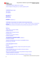
2.3 Software Preparations
2.3.1 Generating Firmware Image (.Hex file)
In order to enable the UCD30xx/UCD3138 device to transfer control from ROM mode to Flash mode after
programming, the firmware image must be generated with a valid Checksum, according to the steps below:
a) Compile the *.c Source file using Code Composer Studio V3.3 and obtain *.x0 file.
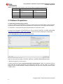
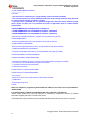
b) Using Texas Instruments UCD3XXX Device GUI (in FUSION_DIGITAL_POWER_DESIGNER
http://www.ti.com/tool/fusion_digital_power_designer) create Intel Hex file by following the 3 steps below:
i. Select “x0 to Hex Tool” option in the GUI as shown below
Figure 10: “X0 to Hex Tool” option of FUSION_DIGITAL_POWER_DESIGNER Device GUI
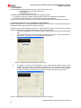
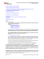
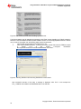
ii. Browse and locate the .xo file on the PC
iii. Select radio button indicating “Calculate and export valid checksum” option. This will put the device in
Flash mode after successful programming with FlashRunner (however, if for any reason, it is desired to
retain the device in ROM mode after successful programming, then select the “Export bad Checksum (Stay
in ROM)” option)
Copyright © 2012, Texas Instruments Incorporated
8
Using FlashRunner FR03TXI0 to Program UCD3020/3028/3040 and UCD3138
SLUA654 - August 2012
Figure 11: Intel Hex file creation with “Calculate and export valid checksum” option
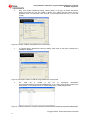
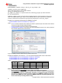
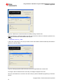
iv. Click “Convert”. The Intel .Hex file will be created at the same location as the .xo file and the following
screen will be displayed upon successful conversion
Figure 12. Intel Hex file creation with “Calculate and export valid checksum” option
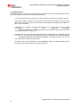
2.3.2 Installing FlashRunner Control Panel Utility
Please review Section 7 FlashRunner Control Panel in FlashRunner Programmer’s Manual for detailed
information regarding use of FlashRunner Control Panel Utility.
Using the CD-ROM provided, install the FlashRunner system software on the PC. The software setup installs
Copyright © 2012, Texas Instruments Incorporated
9
Using FlashRunner FR03TXI0 to Program UCD3020/3028/3040 and UCD3138
SLUA654 - August 2012
all of the required components on the hard drive. These components include:
- The FlashRunner Control Panel utility (GUI)
- Script examples
- Documentation in PDF format
The FlashRunner Control Panel utility is used for the following purposes:
1. To create and set up the necessary files and licenses in SD card for Stand-alone programming
2. To send commands from host PC to instruct FR03 to program target devices
In this document, only the requirements and procedures related to stand-alone programming are covered.
2.3.3 Generating Binary File for programming using FlashRunner
Please review Section 7.1.3 Creating FlashRunner Binary Files in FlashRunner Programmer’s Manual for
detailed information regarding subject covered in this section.
FlashRunner accepts the firmware image files in a .FRB (FlashRunner Binary) format. In order to generate
the .frb image file from the Intel Hex file the following steps must be executed.
i.
Connect the FlashRunner unit to host PC using the 9-pin serial cable and provide 7.5VDC power
input
ii.
Launch the FlashRunner Control Panel utility. Select Start > Programs > SofTec Microsystems >
FlashRunner > Control Panel. The Control Panel utility will open.
Figure 13. FrashRunner Control Panel utility upon launch
iii.
To establish a connection with FlashRunner, on the “Communication Settings” section, select
“FlashRunner serial version”, and specify the COM port you are using and the baud rate (by
default, FlashRunner communicates at 115200 bps). Then click “Connect”. After successful
connection is made, the Control Panel responds with “PONG>” message, as shown below.
Figure 14. FlashRunner Control Panel utility after communication with host PC
Copyright © 2012, Texas Instruments Incorporated
10
Using FlashRunner FR03TXI0 to Program UCD3020/3028/3040 and UCD3138
SLUA654 - August 2012
iv.
Next, click “Create FlashRunner Binary Format (.FRB)”. In the pop up window that opens,
browse and locate the .Hex file created in Section 2.3.1 (select Intel Hex option from the
dropdown menu in Format field). Then click OK. In the example below the PFC_1.xo file was
chosen.
Figure 15. Creating .FRB file using FlashRunner Control Panel
v.
A .FRB file with the specified file name (by default, same name as .Hex file) is created and a
message is displayed.
Figure 16. Successful creation of .FRB file using FlashRunner Control Panel
vi.
The
.FRB
file
is
located
in
the
PC
at
C:\Program
Files\SofTec
Microsystems\FlashRunner\ControlPanel\BINARIES. A .txt creation report is also created at the
same location. In the example below, a .FRB file named PFC_1.FRB was generated.
Figure 17. .FRB file created at C:\Program Files\SofTec Microsystems\FlashRunner\ControlPanel\BINARIES
Copyright © 2012, Texas Instruments Incorporated
11
Using FlashRunner FR03TXI0 to Program UCD3020/3028/3040 and UCD3138
SLUA654 - August 2012
2.3.4 Generating Script File for Standalone Programming
Please review Section.3 Scripts in FlashRunner Programmer’s Manual for detailed information regarding
subject covered in this section.
Standalone mode operation of the FlashRunner is enabled by the use of Script files. Script files are text files,
stored in the SD card, which contain a sequence of FlashRunner commands. With FlashRunner FR03, for
standalone programming, the filename SCRIPT0.FRS’ must be used for the script file. The automatic
execution of the sequence of commands in the SCRIPT0.FRS script file is triggered when the red ‘START’
push-button on the FlashRunner FR03 is depressed.
When FlashRunner begins executing the script file, the “BUSY” LED turns on. During script file execution
FlashRunner will not answer host commands. Script file execution ends either after FlashRunner has
executed the last command in the script, or immediately after the first command in the script that is not
successful. When script file execution ends, the “BUSY” LED turns off and either the “PASS” or “FAIL” LED
turns on, depending on whether the last command executed was successful or not.
The flowchart below summarizes the typical sequence of commands executed in the script file for standalone
operation.
Figure 18. FlashRunner Script development
Please review Section.2 FlashRunner Commands in FlashRunner Programmer’s Manual for detailed
information regarding command statements executed by FlashRunner.
TI has partnered with SMH Technologies to develop sample scripts that can be used for fast and reliable
programming of UCD3xxx devices, from ROM mode as well as Flash mode (Firmware Update). The
example scripts provided in the next 2 sections can be used for programming the UCD3xxx devices.
2.3.4.1 Sample Script for Programming UCD3xxx device in ROM Mode
A sample script for programming of UCD30xx devices from ROM mode is provided below. This script
programs all 32kB of the program flash and 2kB of data flash in UCD3xxxx devices and performs verification.
In verification step, the FlashRunner performs Checksum calculation on the .FRB image file independently
and FlashRunner also instructs the UCD3xxx ROM to perform Checksum calculation on the downloaded
firmware image in the device. By comparing these 2 calculations, the FlashRunner determines whether a
valid programming has been executed or not.
;
Copyright © 2012, Texas Instruments Incorporated
12
Using FlashRunner FR03TXI0 to Program UCD3020/3028/3040 and UCD3138
SLUA654 - August 2012
; FLASHRUNNER SCRIPT EXAMPLE FOR TI UCD3020
;
; Use this example as a starting point for your specific programming needs
;
;
; --------------------; HARDWARE CONNECTIONS
; --------------------; DIO1 (SCLK)
; DIO2 (SDATA)
;
; Turns off logging
#LOG_OFF
; Halt on errors
#HALT_ON FAIL
; Sets device
TCSETDEV TI UCD3020 TI_D
; ---------------------------------------------------------------------------------------------------------------; ATTENTION: for more information on the available commands and parameter tuning
; please visit our website: http:\www.smh-tech.com, click on 'Support & download' menu, Download Area
section and
; 'Application Note' subsection and download the document related to the specific programming algorithm
; ---------------------------------------------------------------------------------------------------------------;---------; SETTINGS
;---------; Target voltage, mV (change as needed)
TCSETPAR VDD 3300
; VDD Rise-Time, ms (change as needed)
TCSETPAR PWUP 1
; VDD Fall-Time, ms (change as needed)
TCSETPAR PWDOWN 1
; I2C clock frequency, Hz (change as needed)
; For this device the maximum clock frequency is 400000 Hz
TCSETPAR SCLK 400000
; Image file to be programmed (must be placed in the \BINARIES directory)
TPSETSRC FILE FLASH.FRB
;--------------------------; START PROGRAMMING SESSION
;--------------------------TPSTART
; Mass erases complete Flash Memory, Program memory, Data memory (C/F/E)
TPCMD MASSERASE C
; Erase Program/Data page (F/E) (change address and length as needed)
;TPCMD ERASE F $10000 $8000
; Blank checks Program/Data (F/E) memory (change address and length as needed)
; TPCMD BLANKCHECK F $10000 $8000
; Programs Program/Data (F/E) memory (change addresses and length as needed)
Copyright © 2012, Texas Instruments Incorporated
13
Using FlashRunner FR03TXI0 to Program UCD3020/3028/3040 and UCD3138
SLUA654 - August 2012
TPCMD PROGRAM F $10000 $10000 $8000
TPCMD PROGRAM E $18800 $18800 $800
; Verifies Program/Data (F/E) memory (change source, target address and length as needed)
; If you want you can choose between two types of verification:
; 1) CheckSum method (S) (Recommended)
; 2) Read-Out method (R)
TPCMD VERIFY F S $10000 $10000 $8000
TPCMD VERIFY E S $18800 $18800 $800
; Run program.
; Works only if issued in the same session as PROGRAM command.
; TPCMD RUN
; Ends programming block
TPEND
Additional points to note:
- In the TCSETDEV command, only the following device name options are allowed: UCD3020,
UCD3028, UCD3040 and UCD3138
Examples:
TCSETDEV TI UCD3020 TI_D
TCSETDEV TI UCD3028 TI_D
TCSETDEV TI UCD3040 TI_D
TCSETDEV TI UCD3138 TI_D
-
The TCSETPAR SCLK 400000 command sets the clock frequency (in Hz) for PMBUS protocol.
Either 100kHz or 400kHz can be used. 400kHz is recommended for fast programming. A highfrequency capacitor (CHF in Figure.9) may be necessary to support data transfer at 400kHz.
-
In the TPSETRC command, the name of the FlashRunner Binary file (.FRB) must match the
name of the .FRB file that was generated in section 2.3.3
Example:
TPSETSRC FILE PFC_1.FRB
-
The actual programming of the device is executed by the TPCMD PROGRAM command with F
option for programming the Program flash and E option for programming the Data flash in UCD3xxx
devices. Additionally, parameters must be specified in this command to specify the exact starting
address and length (# of bytes) that need to programmed in the UCD3xxx device.
-
The VERIFY command (with S option) implements the Checksum calculation described earlier, for
the memory locations specified by the starting address and length (# of bytes).
-
For Standalone programming with FR03, the script file must be named as SCRIPT0.FRS
2.3.4.2 Sample Script for Programming UCD3xxx device in Flash Mode (Firmware Update)
For updating the firmware in UCD3xxx device i.e. for re-programming the firmware image, it is necessary to
first send the device back to the ROM mode. This is accomplished by adding one more command, known as
‘ROMBACK’ command, to the script used for programming in ROM mode. The ROMBACK command is
inserted immediately after the TPSTART command in the script. All other commands in the ROM mode
programming script are retained for Flash mode programming as well.
The ROMBACK statement in the script sends a PMBUS command to the UCD3xxx device forcing it to enter
the ROM mode. It is also possible to implement a password requirement in this step in order to avoid
accidental re-programming or for added data security. The pre-existing firmware in the device must be
capable of recognizing and implementing this PMBUS function.
Command syntax:
Copyright © 2012, Texas Instruments Incorporated
14
Using FlashRunner FR03TXI0 to Program UCD3020/3028/3040 and UCD3138
SLUA654 - August 2012
TPCMD ROMBACK <command> <delay> <device_id> <pw_length> <pw>
command Command to return to ROM mode
delay Delay [msec] before a new boot ROM command.
device_ID UCD3XXX device ID code
pw_length If pw_length IS ‘0’ no password will be sent, otherwise pw_length byte will be transmitted
pw User defined password
ROMBACK command is used to send device back to ROM mode when a customer firmware is running on the
device. The command, device_ID and pw are user definable. Moreover pw is optional and if no password
protection is desired then the requirement for pw is ignored by assigning the ‘0’ value to pw_length.
Example for non-password implementation of ROMBACK command:
TPCMD ROMBACK $D9 100 UCD3000ISO1|1.0.2|090707 0
where,
- the ‘D9’ command resets the device without the need for a password (this command must be defined
in the source code of the pre-existing firmware)
- 100 ms is the delay time to allow device to enter ROM mode
- UCD3000ISO1|1.0.2|090707 is the Device ID of the pre-existing firmware on the device (obtained
from UCD3xxx Device GUI as shown below)
Figure 19. Reading UCD3xxx Device ID using UCD3xxx Device GUI
Examples of ROMBACK command with 1, 2 or 4-byte password implementation shown in table below:
TPCMD ROMBACK $26 100 UCD3000ISO1|1.0.2|090707 4 $34129078
TPCMD ROMBACK $25 100 UCD3000ISO1|1.0.2|090707 2 $3456
TPCMD ROMBACK $24 100 UCD3000ISO1|1.0.2|090707 1 $12
where,
Password
Password Command
Byte Option Code
Byte 1
Byte 2
Byte 3
Byte 4
1
0x24
0x12
2
0x25
0x56
0x34
4
0x26
0x78
0x90
0x12
0x34
NOTE: In order to implement the ROMBACK command successfully:
- The Device ID of the pre-existing firmware image of the device must be known
- The pre-existing firmware image on the UCD3xxx device MUST be capable of recognizing the
PMBUS command (such as a standard D9 command for non-password option and specific
user-defined commands for password option) called by the ROMBACK statement to force the
device to enter ROM mode. This requires the PMBUS command to be properly defined in the
source code of the pre-existing firmware image.
Copyright © 2012, Texas Instruments Incorporated
15
Using FlashRunner FR03TXI0 to Program UCD3020/3028/3040 and UCD3138
SLUA654 - August 2012
Also, in all the examples above, a delay time of 100ms is used. Special functions MUST be
included in the source code of the pre-existing firmware image in order to allow the device to
return to ROM mode reliably within 100ms. If these methods are not implemented then a
delay time of at least 3000ms will be necessary for UCD3020/3028/3040 and a delay time of at
least 2000ms will be necessary for UCD3138.
Section 4 of this document provides a detailed discussion regarding source code requirements for
implementing the ROMBACK command examples listed above.
-
The complete example script file for programming in Flash mode is provided below and the ROMBACK
command needed is highlighted in boldface. In this script example, the ROMBACK command is implemented
with non-password option (to implement password security simply comment out the ROMBACK statement
shown below and uncomment the ROMBACK statement for the desired password option).
;
; FLASHRUNNER SCRIPT EXAMPLE FOR TI UCD3020
;
; Use this example as a starting point for your specific programming needs
;
;
; --------------------; HARDWARE CONNECTIONS
; --------------------; DIO1 (SCLK)
; DIO2 (SDATA)
;
; Turns off logging
#LOG_OFF
; Halt on errors
#HALT_ON FAIL
; Sets device
TCSETDEV TI UCD3020 TI_D
; ---------------------------------------------------------------------------------------------------------------; ATTENTION: for more information on the available commands and parameter tuning
; please visit our website: http:\www.smh-tech.com, click on 'Support & download' menu, Download Area
section and
; 'Application Note' subsection and download the document related to the specific programming algorithm
; ---------------------------------------------------------------------------------------------------------------;---------; SETTINGS
;---------; Target voltage, mV (change as needed)
TCSETPAR VDD 3300
; VDD Rise-Time, ms (change as needed)
TCSETPAR PWUP 1
; VDD Fall-Time, ms (change as needed)
TCSETPAR PWDOWN 1
; I2C clock frequency, Hz (change as needed)
; For this device the maximum clock frequency is 400000 Hz
TCSETPAR SCLK 400000
; Image file to be programmed (must be placed in the \BINARIES directory)
TPSETSRC FILE FLASH.FRB
;--------------------------Copyright © 2012, Texas Instruments Incorporated
16
Using FlashRunner FR03TXI0 to Program UCD3020/3028/3040 and UCD3138
SLUA654 - August 2012
; START PROGRAMMING SESSION
;--------------------------TPSTART
; This instruction is needed only for re-programming of device (Firmware UPDATE)
; This instruction permits to restore ROM mode from Flash mode (change command, delay, Device ID
as needed, password length, password as needed)
; If you don't have a password put '0' in password length field, otherwise indicate password length
(max 4 bytes) and then put it on password field (refer TI Application Note for related firmware
requirements)
TPCMD ROMBACK $D9 100 UCD3000ISO1|1.0.2|090707 0
; TPCMD ROMBACK $26 100 UCD3000ISO1|1.0.2|090707 4 $34129078
; TPCMD ROMBACK $26 100 UCD3000ISO1|1.0.2|090707 4 $34129078
; TPCMD ROMBACK $26 100 UCD3000ISO1|1.0.2|090707 4 $34129078
; Mass erases complete Flash Memory, Program memory, Data memory (C/F/E)
TPCMD MASSERASE C
; Erase Program/Data page (F/E) (change address and length as needed)
;TPCMD ERASE F $10000 $8000
; Blank checks Program/Data (F/E) memory (change address and length as needed)
; TPCMD BLANKCHECK F $10000 $8000
; Programs Program/Data (F/E) memory (change addresses and length as needed)
TPCMD PROGRAM F $10000 $10000 $8000
TPCMD PROGRAM E $18800 $18800 $800
; Verifies Program/Data (F/E) memory (change source, target address and length as needed)
; If you want you can choose between two types of verification:
; 1) CheckSum method (S) (Recommended)
; 2) Read-Out method (R)
TPCMD VERIFY F S $10000 $10000 $8000
TPCMD VERIFY E S $18800 $18800 $800
; Run program.
; Works only if issued in the same session as PROGRAM command.
; TPCMD RUN
; Ends programming block
TPEND
NOTE: For standalone programming with FlashRunner FR03, the file name of the script file MUST be
‘SCRIPT0.FRS’.
2.3.5 Sending Binary (.FRB) & Script (SCRIPT0.FRS) files to SD card in FlashRunner
Please review Section.5 SD Card File Structure in FlashRunner Programmer’s Manual for detailed
information regarding the subject covered in this section.
The FlashRunner unit is provided with a pre-formatted SD card with the file structure shown in Figure 20.
Copyright © 2012, Texas Instruments Incorporated
17
Using FlashRunner FR03TXI0 to Program UCD3020/3028/3040 and UCD3138
SLUA654 - August 2012
Figure 20. SD Card file structure after formatting by FlashRunner
The final preparation step for standalone programming with FR03 involves installing the .FRB file created in
section 2.3.3 and the SCRIPT0.FRS script file created in section 2.3.4 at the appropriate locations in the SD
card. In order to accomplish this, the following steps need to be performed:
i.
Insert the SD card provided into the FlashRunner unit.
ii.
Click “Send FlashRunner Binary”. In the pop-up window, browse and locate the .FRB file created
in
section
2.3.3.
at
the
location
C:\Program
Files\SofTec
Microsystems\FlashRunner\ControlPanel\BINARIES. Click “Start”.
Figure 21. Sending .FRB file to SD card using FlashRunner Control Panel
After successful execution of this step, a message is displayed. Click “Exit”. In this example the
PFC_1.FRB file was installed in the BINARIES folder in the SD card.
Copyright © 2012, Texas Instruments Incorporated
18
Using FlashRunner FR03TXI0 to Program UCD3020/3028/3040 and UCD3138
SLUA654 - August 2012
Figure 22. FlashRunner Control Panel after successfully sending .FRB file to SD
Note: The filename of .FRB file installed in the SD card must be the same as the filename specified in the
TPSETRC command line of the SCRIPT0.FRS script file.
Example:
TPSETSRC FILE PFC_1.FRB
iii Next, Click “Send Script”. In the pop-up window, browse and locate the SCRIPT0.FRS script file created in
section 2.3.4 and click “Start”.
Figure 23. Sending script file SCRIPT0.FRs file to SD card using FlashRunner Control Panel
Once again, after successful execution of this step, a message is displayed. Click “Exit”.
After this, the FlashRunner unit with the SD card is ready to perform Standalone programming of UCD3xxx
devices.
Copyright © 2012, Texas Instruments Incorporated
19
Using FlashRunner FR03TXI0 to Program UCD3020/3028/3040 and UCD3138
SLUA654 - August 2012
2.3.6 Additional Notes
The FlashRunner unit is provided with all the licenses and algorithm files related to programming UCD3xxx
devices pre-installed in the SD card at the appropriate locations.
-
TI_D.ALG and DEFAULT.ALG files must be present inside the ALGOS directory inside the SD card
-
Type “FSCD ALGOS” command in Control Panel and enter the ALGOS directory of SD card. Next
type “FSLS” command to list the files and verify the required files are available. Enter “FSCD \” to
return to the root directory
-
If these files are not present then save DEFAULT.ALG and TI_D.ALG files (provided by SMH
technologies)
in
local
path
“C:\Program
Files\SofTec
Microsystems\FlashRunner\ControlPanel\ALGOS” and install them inside the SD card using
“Send Algorithm” option of Control Panel
-
In a similar manner, ensure that all required licence files are installed inside the LICENSES directory
of the SD card. If not, the save all the license files (.LIC) in local path “C:\Program Files\SofTec
Microsystems\FlashRunner\ControlPanel\LICENSES” and install the files in the SD card
using “Send Licences” option of Control Panel.
-
The licence files (.LIC) are exclusive to the FlashRunner FR03 unit serial # being used for
programming and also the UCD3xxx programming algorithm.
Copyright © 2012, Texas Instruments Incorporated
20
Using FlashRunner FR03TXI0 to Program UCD3020/3028/3040 and UCD3138
SLUA654 - August 2012
3. FlashRunner FR03 Standalone Programming Procedure
Programming the FlashRunner involves the following steps:
1. Power up the FlashRunner FR03
2. Insert SD card with all the requisite files installed inside. Use Checklist below:
• Ensure SCRIPT0.FRS script file & firmware image (.FRB) file are installed in SD card at correct
location
• Ensure that the correct Device name is used in the TCSETDEV statement in the script file
• Ensure that the filename of the firmware image file (.FRB) in the SD card matches the file name
specified in the TPSETSRC statement in the script file
• Ensure that correct Device ID of the pre-existing firmware is used in the ROMBACK statement in
the script file (for firmware update)
• Ensure that the pre-existing firmware can support the PMBUS commands in ROMBACK
statement (for firmware update)
• Ensure the correct password is used in ROMBACK statement (if desired, for firmware update)
• Ensure that all licenses of the FR03 unit being used are installed in SD card at correct location
• Ensure that TI_D.ALG and DEFAULT.ALG algorithm files are loaded in the SD card at correct
location
3. Connect interface cable between the DUT board (with the device to be programmed) and the FR03
unit ISP connector
• Ensure that the CHF capacitor is properly installed on the interface cable to support highfrequency PMBUS protocol during programming
4. Provide 3.3V bias to the target Device (can be biased either with external power supply or directly
from the VPROG0 line from FlashRunner ISP connector)
5. Press the red START button on the FR03 unit
The response from the status LEDs is summarized below:
Scenario
During programming
After successful programming and verification1 by FR03
If programming is unsuccessful2
LED status
the yellow BUSY status LED is lit up
the green PASS status LED is lit up
the red FAIL status LED is lit up
1
- In verification step, the FlashRunner performs Checksum calculation on the .FRB image file independently
and FlashRunner also instructs the UCD3xxx ROM to perform Checksum calculation on the downloaded
firmware image in the device. By comparing these 2 calculations, the FlashRunner determines whether a
valid programming has been executed or not. If a valid Checksum was written during .xo file generation step,
then the device will be put in Flash-mode after successful programming. If an invalid Checksum was written
during .xo file generation step, then the device will stay in ROM mode after successful programming.
2
– There are several reasons related to set-up which can cause programming to be unsuccessful. A
checklist is provided in table below for trouble-shooting purpose:
Reason for unsuccessful programming
ROMBACK command Password is incorrect
Delay time parameter in ROMBACK command is
insufficient
ROMBACK command is not included in script file
when device to be programmed is in Flash mode
DEVICE ID in ROMBACK statement is incorrect
Invalid Device name is used in TCSETDEV
statement
Script file name is not SCRIPT0.FRS
The .FRB file name in SD card does not match
.FRB file name in script file TPSETRC statement
CHF capacitor is not properly installed or is too
small value to support 400khz PMBUS protocol
PMBUS command in ROMBACK statement is
not recognized by the pre-existing firmware on
the device
Troubleshooting Guideline
Use correct password, according to definition in preexisting firmware in the device
Increase delay time or add additional code to implement
faster reset according to Section 4.1 in this document
Add ROMBACK statement in SCRIPT0.FRS file
Use correct DEVICE ID according to pre-existing
firmware in the device in ROMBACK statement
Use only valid Device names (UCD3020, UCD3028,
UCD3040 and UCD3138) in TCSETDEV statement.
Change Script file name to ‘SCRIPT0.FRS’
Change .FRB file name in TPSETRC statement of script
file to match .FRB file installed in SD card
Check CHF capacitor installation or increase CHF
capacitor value
Pre-existing firmware in device must support PMBUS
command in ROMBACK statement. Firmware update
feature cannot be used if this condition is not met.
Copyright © 2012, Texas Instruments Incorporated
21
Using FlashRunner FR03TXI0 to Program UCD3020/3028/3040 and UCD3138
SLUA654 - August 2012
4. Source Code Requirements for Successful ROMBACK
Command Implementation in Flash Mode Programming
If Firmware Update feature using FlashRunner is desired, then it is important to ensure that the pre-existing
firmware image on the device has the capability to recognize the PMBUS command in the ROMBACK
statement and to send the device back to the ROM mode, from where it can be re-programmed. This means
that the PMBUS command must be properly defined in the source code of the pre-existing image in the
device.
ROMBACK Command syntax:
TPCMD ROMBACK <command> <delay> <device_id> <pw_length> <pw>
command Command to return to ROM mode
delay Delay [msec] before a new boot ROM command
device_ID UCD3XXX device ID code
pw_length If pw_length IS ‘0’ no password will be sent, otherwise pw_length byte will be transmitted
pw User defined password
Command parameters:
This command is used to go back to ROM mode when a customer firmware is running on the device. The
command, device_ID and pw parameters are user definable. Moreover pw is optional and if no password
protection is desired then the requirement for pw is ignored by assigning the ‘0’ value to pw_length.
4.1 Implementing Fast Device Re-programming
The PMBUS command in the ROMBACK statement will deliberately reset the device and force invalid
checksum to send it back to ROM mode. A delay time has to be specified in the ROMBACK command,
allowing enough time for the device to enter ROM mode. However, this delay time must be kept to a
minimum to enable fast re-programming. There are 2 methods recommended to enable delay time of less
than 100ms:
1. One method to force a quick reset in less than 100ms is by pointing the device to an illegal memory
location during the PMBUS command execution. This is easily implemented by adding the code highlighted
in boldface in the ‘interrupts.c’ file:
case 12: //zero_integrity_word();
DecRegs.PFLASHILOCK = 0x42DC157E;// Write key to Program Flash Interlock Register
{
register Uint32 * program_index = (Uint32 *) 0x19000; //store destination address for erase checksum
program
register Uint32 * source_index = (Uint32 *)zero_integrity_word; //Set source address of PFLASH;
register Uint32 zoiw_size = (Uint32 *)zoiw_end - (Uint32 *)zero_integrity_word;//Calculate lenght
register Uint32 counter;
for(counter=0; counter < zoiw_size; counter++) //Copy program from PFLASH to RAM
{
*(program_index++)=*(source_index++);
}
{
register FUNC_PTR func_ptr;
func_ptr=(FUNC_PTR)0x19000;//Set function to 0x19000
func_ptr();
//now jump out into space and force a reset
func_ptr=(FUNC_PTR)0x200000;//Set function to 0x200000
func_ptr();
} //execute erase checksum
return;
2. Another method to force a quick reset in less than 100ms is by implementing a software reset using the
Copyright © 2012, Texas Instruments Incorporated
22
Using FlashRunner FR03TXI0 to Program UCD3020/3028/3040 and UCD3138
SLUA654 - August 2012
system exception control register SYSECR bit in the ‘clear_program_flash.c’ file, highlighted in boldface
below:
void zero_out_integrity_word(void)
{
DecRegs.FLASHILOCK.all = 0x42DC157E;// Write key to Program Flash Interlock Register
DecRegs.MFBALR1.all = MFBALRX_BYTE0_BLOCK_SIZE_32K; //enable program flash write
program_flash_integrity_word = 0;
DecRegs.MFBALR1.all = MFBALRX_BYTE0_BLOCK_SIZE_32K + //expand program flash out to 4x real
size
MFBALRX_BYTE0_RONLY;
while(DecRegs.PFLASHCTRL.bit.BUSY != 0)
{
; //do nothing while it programs
}
SysRegs.SYSECR.bit.RESET = 2; //reset device
return;
}
NOTE: One of these reset methods described above must be implemented in the source code of preexisting firmware on the device in order to be able to use a delay time of 100ms in the ROMBACK
command. If these methods are not implemented then a delay time of 3000ms will be necessary for
UCD3020/3028/3040 and a delay time of 2000ms will be necessary for UCD3138.
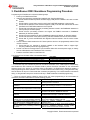
4.2 Implementing Password Protection during Firmware Update
FlashRunner also offers the user the option to implement password protection during firmware update. The
password can be 1 byte, 2 bytes or 4 bytes long and is defined by the user. The code highlighted in boldface
below illustrates examples of how to implement the 1, 2, and 4 bit passwords and related PMBUS
commands (shown in table below). One of the password options may be chosen and the related code should
be included in ‘pmbus.c’ in the source code of pre-existing firmware on the device. The user has flexibility to
define the exact command code.
Password
Password Command
Byte Option Code
Byte 1
Byte 2
Byte 3
Byte 4
1
0x24
0x12
2
0x25
0x56
0x34
4
0x26
0x78
0x90
0x12
0x34
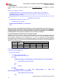
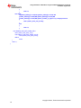
// look at command byte from a write perspective
int32 pmbus_write_message(void)
{
switch (pmbus_buffer[0])
{
case PMBUS_CMD_ROM_MODE:
return pmbus_write_rom_mode();
case 0x24:
if((pmbus_buffer[1] == 0x12) && (pmbus_number_of_bytes == 3)) //1 byte password
{
return pmbus_write_rom_mode();
}
else
{
return 0;
}
case 0x25:
if((pmbus_buffer[2]
==
0x34)
&&
(pmbus_buffer[1]
==
0x56)
&&
(pmbus_number_of_bytes == 4)) //1 word password
{
return pmbus_write_rom_mode();
}
else
Copyright © 2012, Texas Instruments Incorporated
23
Using FlashRunner FR03TXI0 to Program UCD3020/3028/3040 and UCD3138
SLUA654 - August 2012
{
return 0;
}
case 0x26:
if((pmbus_buffer[1] == 0x4) && (pmbus_buffer[2] == 0x78) &&
(pmbus_buffer[3] == 0x90) && (pmbus_buffer[4] == 0x12) &&
(pmbus_buffer[5] == 0x34) && (pmbus_number_of_bytes == 7)) //4 byte password
{
return pmbus_write_rom_mode();
}
else
{
return 0;
}
case PMBUS_CMD_MFR_PARM_INFO:
return pmbus_write_parm_info();
case PMBUS_CMD_MFR_PARM_VALUE:
return pmbus_write_parm_value();
default:
break;
}
return 0;
}
Copyright © 2012, Texas Instruments Incorporated
24
Using FlashRunner FR03TXI0 to Program UCD3020/3028/3040 and UCD3138
SLUA654 - August 2012
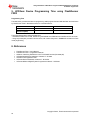
5. UCD3xxx Device Programming Time using FlashRunner
FR03
Programming Time
The table below provides time taken for programming 32kB program flash and 2kB data flash and verification
by FlashRunner FR03 in Standalone mode, for a UCD3040 device:
ROM Mode
Flash Mode
(firmware update)
400KHz PMBUS
3.4 sec
3.6 sec
100kHz PMBUS
6.2 sec
6.4 sec
The measurements above were generated from:
- UCD3040 PR799A Control Card, biased using the PMBUS line VPROG0 from FlashRunner ISP connector
- Using script examples provided in this document, with 100ms delay time in ROMBACK command for Flash
mode programming
6. References
1.
2.
3.
4.
5.
6.
7.
FlashRunner FR03 – User’s Manual
FlashRunner FR03 – Programmer’s Manual
AN00153: Interfacing FlashRunner with TI UCD30XX Devices (DC10496.pdf)
UCD3040/20/28 Device Datasheet, Literature # - SLU868
UCD30xx Flash Application Note
UCD3138 Device Datasheet, Literature # - SLUSAP2
UCD3138 ARM and Digital System Programmer’s Manual – SLUU994
Copyright © 2012, Texas Instruments Incorporated
25
Using FlashRunner FR03TXI0 to Program UCD3020/3028/3040 and UCD3138
SLUA654 - August 2012
IMPORTANT NOTICE
Texas Instruments Incorporated and its subsidiaries (TI) reserve the right to make corrections, modifications, enhancements,
improvements, and other changes to its products and services at any time and to discontinue any product or service without notice.
Customers should obtain the latest relevant information before placing orders and should verify that such information is current and
complete. All products are sold subject to TI’s terms and conditions of sale supplied at the time of order acknowledgment. TI warrants
performance of its hardware products to the specifications applicable at the time of sale in accordance with TI’s standard warranty.
Testing and other quality control techniques are used to the extent TI deems necessary to support this warranty. Except where
mandated by government requirements, testing of all parameters of each product is not necessarily performed. TI assumes no liability
for applications assistance or customer product design. Customers are responsible for their products and applications using TI
components. To minimize the risks associated with customer products and applications, customers should provide adequate design and
operating safeguards. TI does not warrant or represent that any license, either express or implied, is granted under any TI patent right,
copyright, mask work right, or other TI intellectual property right relating to any combination, machine, or process in which TI products or
services are used. Information published by TI regarding third-party products or services does not constitute a license from TI to use
such products or services or a warranty or endorsement thereof. Use of such information may require a license from a third party under
the patents or other intellectual property of the third party, or a license from TI under the patents or other intellectual property of TI.
Reproduction of TI information in TI data books or data sheets is permissible only if reproduction is without alteration and is
accompanied by all associated warranties, conditions, limitations, and notices. Reproduction of this information with alteration is an
unfair and deceptive business practice. TI is not responsible or liable for such altered documentation. Information of third parties may be
subject to additional restrictions. Resale of TI products or services with statements different from or beyond the parameters stated by TI
for that product or service voids all express and any implied warranties for the associated TI product or service and is an unfair and
deceptive business practice. TI is not responsible or liable for any such statements. TI products are not authorized for use in safetycritical applications (such as life support) where a failure of the TI product would reasonably be expected to cause severe personal injury
or death, unless officers of the parties have executed an agreement specifically governing such use. Buyers represent that they have all
necessary expertise in the safety and regulatory ramifications of their applications, and acknowledge and agree that they are solely
responsible for all legal, regulatory and safety-related requirements concerning their products and any use of TI products in such safetycritical applications, notwithstanding any applications-related information or support that may be provided by TI. Further, Buyers must
fully indemnify TI and its representatives against any damages arising out of the use of TI products in such safety-critical applications. TI
products are neither designed nor intended for use in military/aerospace applications or environments unless the TI products are
specifically designated by TI as military-grade or "enhanced plastic." Only products designated by TI as military-grade meet military
specifications. Buyers acknowledge and agree that any such use of TI products which TI has not designated as military-grade is solely
at the Buyer's risk, and that they are solely responsible for compliance with all legal and regulatory requirements in connection with such
use. TI products are neither designed nor intended for use in automotive applications or environments unless the specific TI products
are designated by TI as compliant with ISO/TS 16949 requirements. Buyers acknowledge and agree that, if they use any nondesignated products in automotive applications, TI will not be responsible for any failure to meet such requirements. Following are URLs
where you can obtain information on other Texas Instruments products and application solutions:
Products
Applications
Audio www.ti.com/audio
Automotive and Transportation www.ti.com/automotive
Amplifiers amplifier.ti.com
Communications and Telecom www.ti.com/communications
Data Converters dataconverter.ti.com
Computers and Peripherals www.ti.com/computers
DLP® Products www.dlp.com
Consumer Electronics www.ti.com/consumer-apps
DSP dsp.ti.com
Energy and Lighting www.ti.com/energy
Industrial www.ti.com/industrial
Clocks and Timers www.ti.com/clocks
Interface interface.ti.com
Medical www.ti.com/medical
Logic logic.ti.com
Security www.ti.com/security
Power Mgmt power.ti.com
Space, Avionics and Defense www.ti.com/space-avionics-defense
Microcontrollers microcontroller.ti.com
Video and Imaging www.ti.com/video
RFID www.ti-rfid.com
OMAP Mobile Processors www.ti.com/omap
Wireless Connectivity www.ti.com/wirelessconnectivity
TI E2E Community Home Page e2e.ti.com
Mailing Address: Texas Instruments, Post Office Box 655303, Dallas, Texas 75265
Copyright © 2012, Texas Instruments Incorporated
26
IMPORTANT NOTICE
Texas Instruments Incorporated and its subsidiaries (TI) reserve the right to make corrections, enhancements, improvements and other
changes to its semiconductor products and services per JESD46, latest issue, and to discontinue any product or service per JESD48, latest
issue. Buyers should obtain the latest relevant information before placing orders and should verify that such information is current and
complete. All semiconductor products (also referred to herein as “components”) are sold subject to TI’s terms and conditions of sale
supplied at the time of order acknowledgment.
TI warrants performance of its components to the specifications applicable at the time of sale, in accordance with the warranty in TI’s terms
and conditions of sale of semiconductor products. Testing and other quality control techniques are used to the extent TI deems necessary
to support this warranty. Except where mandated by applicable law, testing of all parameters of each component is not necessarily
performed.
TI assumes no liability for applications assistance or the design of Buyers’ products. Buyers are responsible for their products and
applications using TI components. To minimize the risks associated with Buyers’ products and applications, Buyers should provide
adequate design and operating safeguards.
TI does not warrant or represent that any license, either express or implied, is granted under any patent right, copyright, mask work right, or
other intellectual property right relating to any combination, machine, or process in which TI components or services are used. Information
published by TI regarding third-party products or services does not constitute a license to use such products or services or a warranty or
endorsement thereof. Use of such information may require a license from a third party under the patents or other intellectual property of the
third party, or a license from TI under the patents or other intellectual property of TI.
Reproduction of significant portions of TI information in TI data books or data sheets is permissible only if reproduction is without alteration
and is accompanied by all associated warranties, conditions, limitations, and notices. TI is not responsible or liable for such altered
documentation. Information of third parties may be subject to additional restrictions.
Resale of TI components or services with statements different from or beyond the parameters stated by TI for that component or service
voids all express and any implied warranties for the associated TI component or service and is an unfair and deceptive business practice.
TI is not responsible or liable for any such statements.
Buyer acknowledges and agrees that it is solely responsible for compliance with all legal, regulatory and safety-related requirements
concerning its products, and any use of TI components in its applications, notwithstanding any applications-related information or support
that may be provided by TI. Buyer represents and agrees that it has all the necessary expertise to create and implement safeguards which
anticipate dangerous consequences of failures, monitor failures and their consequences, lessen the likelihood of failures that might cause
harm and take appropriate remedial actions. Buyer will fully indemnify TI and its representatives against any damages arising out of the use
of any TI components in safety-critical applications.
In some cases, TI components may be promoted specifically to facilitate safety-related applications. With such components, TI’s goal is to
help enable customers to design and create their own end-product solutions that meet applicable functional safety standards and
requirements. Nonetheless, such components are subject to these terms.
No TI components are authorized for use in FDA Class III (or similar life-critical medical equipment) unless authorized officers of the parties
have executed a special agreement specifically governing such use.
Only those TI components which TI has specifically designated as military grade or “enhanced plastic” are designed and intended for use in
military/aerospace applications or environments. Buyer acknowledges and agrees that any military or aerospace use of TI components
which have not been so designated is solely at the Buyer's risk, and that Buyer is solely responsible for compliance with all legal and
regulatory requirements in connection with such use.
TI has specifically designated certain components as meeting ISO/TS16949 requirements, mainly for automotive use. In any case of use of
non-designated products, TI will not be responsible for any failure to meet ISO/TS16949.
Products
Applications
Audio
www.ti.com/audio
Automotive and Transportation
www.ti.com/automotive
Amplifiers
amplifier.ti.com
Communications and Telecom
www.ti.com/communications
Data Converters
dataconverter.ti.com
Computers and Peripherals
www.ti.com/computers
DLP® Products
www.dlp.com
Consumer Electronics
www.ti.com/consumer-apps
DSP
dsp.ti.com
Energy and Lighting
www.ti.com/energy
Clocks and Timers
www.ti.com/clocks
Industrial
www.ti.com/industrial
Interface
interface.ti.com
Medical
www.ti.com/medical
Logic
logic.ti.com
Security
www.ti.com/security
Power Mgmt
power.ti.com
Space, Avionics and Defense
www.ti.com/space-avionics-defense
Microcontrollers
microcontroller.ti.com
Video and Imaging
www.ti.com/video
RFID
www.ti-rfid.com
OMAP Applications Processors
www.ti.com/omap
TI E2E Community
e2e.ti.com
Wireless Connectivity
www.ti.com/wirelessconnectivity
Mailing Address: Texas Instruments, Post Office Box 655303, Dallas, Texas 75265
Copyright © 2014, Texas Instruments Incorporated