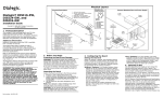
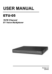
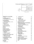
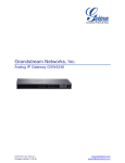
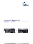
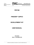
1
PIKA DAYTONA™ Voice Card
Hardware Manual
1.1
TECHNOLOGIES INC.
155 Terrence Matthews Crescent
Kanata, Ontario K2M 2A8
Canada
Tel: 1-613-591-1555
Fax: 1-613-591-1488
© Copyright 1989 - 1996 PIKA Technologies Inc.
All rights reserved. No part of this document may be reproduced, stored in a
retrieval system, or in any other form or by any means, electronic, mechanical,
photocopying, recording or otherwise, without prior written permission of PIKA
Technologies Inc.
This Printing: April 1996
Table of Content
1 INTRODUCTION ..............................................................................1
2 DAYTONA DESCRIPTION .............................................................2
2.1 SWITCHING CAPABILITY .................................................................2
2.2 TELEPHONE LINE PORTS (DOMESTIC VARIANTS) ..........................4
2.3 TELEPHONE LINE PORTS (INTERNATIONAL VARIANTS) ................11
3 HARDWARE INSTALLATION....................................................13
3.1 PC INSTALLATION ........................................................................14
3.1.1 Setting Base I/O Address ......................................................14
3.2 TELEPHONE LINE PORTS SETUP....................................................16
3.2.1 Domestic Variants ................................................................16
3.2.2 International Variants ..........................................................19
3.3 MVIP BUS SETUP ........................................................................22
APPENDIX A MVIP BUS ..................................................................23
APPENDIX B REGULATORY WARNINGS .................................26
B.1 INDUSTRY CANADA INFORMATION ..............................................26
B.2 FCC INFORMATION .....................................................................28
1 Introduction
The PIKA DAYTONA card is family of IBM AT (ISA) bus
compatible DSP resource cards for use in PC based voice
systems. The DAYTONA family provides up to 24 analog
telephone line interfaces in a variety of different configurations.
The cards are fully MVIP bus (Multi-Vendor Interface Protocol)
compliant, allowing them to be interconnected with any other
MVIP compatible cards in the host system.
The following table lists the available variants within the
DAYTONA card family, showing analog line configuration and
DSP audio processing power in MIPS:
Domestic Variants:
MODEL
24P
24L
12P
12L
8P4L
16P8L
POTS Lines
24
0
12
0
8
16
International Variants:
MODEL
POTS Lines
12L-i
12L-i/GT
0
0
DAYTONA Hardware Manual
Analog Loop
Start Lines
0
24
0
12
4
8
DSP MIPS
Analog Loop
Start Lines
12
12
DSP MIPS
60
60
30
30
30
60
30
60
1
2 DAYTONA Description
The DAYTONA family cards are IBM AT (ISA) bus compatible,
providing analog interfaces to telephone lines of various types.
These cards have up to two on board DSP devices, can support
one V-ENGINE DSP module, and an MVIP connector for
interconnection to other compatible devices in the host system.
Both cards provide MVIP compatible circuit switching for 512 time
slots.
2.1 Switching Capability
The DAYTONA supports a central digital switching matrix based
on the industry standard FMIC device. The switch matrix is used
for connecting the audio Input/Outputs of voice/data resources
together, including Line Circuits, DSP devices and MVIP Bus.
DAYTONA Hardware Manual
2
The switch matrix on the card is classed as MVIP Enhanced
Compliant which means it can connect to the MVIP on the full 512
channel switching capability, and can switch internal resources
without using the MVIP Bus.
The following diagram graphically illustrates the digital switching
paths available on the DAYTONA:.
Note that any input to the DAYTONA switch matrix can be
connected to any output of the matrix.
DAYTONA SWITCH
MATRIX
MVIP BUS
MVIP BUS
DSo
0-7
IN
0-7
OUT
0-7
DSi
0-7
DSi
0-7
IN
8-15
OUT
8-15
DSo
0-7
DSPs
DSPs
Out
IN
16-19
OUT
16-19
Lines Circuits
Out
In
Line Circuits
IN
20
DAYTONA Hardware Manual
OUT
20
In
3
2.2 Telephone Line Ports (Domestic Variants)
The DAYTONA card is assembled in a number of configurations,
consisting of combinations of Loop Start and POTS type telecom
line interfaces.
2.2.1 LOOP START Line
DAYTONA VERSIONS: 12L, 24L, 8P4L, 16P8L
Loop Start line interfaces provide a termination which behaves
the same way that a telephone set does when connected to a wall
plug (i.e. PBX or Public Network port). The DAYTONA Loop Start
Line ports initiate outbound calls by going OFFHOOK and dialing,
and they take incoming calls by detecting ringing voltage then
going OFFHOOK.
The DAYTONA card’s dowloadable onboard firmware performs
all real-time related LOOP START line functions including
supervision of RINGING voltage, BATTERY REVERSAL and
LOOP CURRENT DISCONNECT. The card performs signaling
functions including generation of OFFHOOK, DIALING and
HOOKFLASH signals.
The DAYTONA line interface supports high impedance audio
reception during the on-hook state, allowing the card to perform
tasks such as CLASS signaling (Caller I.D.), KT23 signaling (onhook DTMF detection), and high impedance audio logging.
The following specifications apply to the Loop Start Line interface:
Signaling:
DC resistance: 250-325 ohms
DC current range: 18 - 90 mA
Supervision:
Ringing: Voltage detection
Loop current disconnect
Battery reversal (Factory option)
DAYTONA Hardware Manual
4
Transmission:
AC Impedance ONHOOK: > 10Kohm at 20Hz.
AC Impedance OFFHOOK: 600ohms.
The following shows typical applications of Loop Start lines on the
DAYTONA 24L:
DAYTO NA 24L
PBX
or
P U B L IC
NETW O RK
24
L O O P S T A R T L IN E C O N N E C T IO N
PH O NES
PBX
or
24
P U B L IC
NETW ORK
D A YTO N A 24L
B R ID G E D C O N N E C T IO N S
DAYTONA Hardware Manual
5
2.2.2 POTS Line
DAYTONA VERSIONS: 12P, 24P, 8P4L, 16P8L
POTS line (Plain Old Telephone Set) interfaces also known as
SLICS provide talk battery (-48 volts DC) and ringing voltage (90
VAC/20Hz).
The DAYTONA card’s downloadable onboard firmware performs
all real-time related POTS line functions.
The following specifications apply to the DAYTONA family POTS
Line interface:
Current Feed:
DC resistance: 400 ohms
DC current range: 18 - 70 mA
Ringing Voltage:
Cadence: Software programmable.
Power load distribution: programmable.
Zero Cross switching.
Supervision:
OFFHOOK/ONHOOK
Ring Trip
HOOKFLASH
Transmission:
AC Impedance: 600ohms.
DAYTONA Hardware Manual
6
The following shows a typical application of POTS Lines on the
DAYTONA 24P:
P ow er S upply
D A Y TO N A 24P
-48V D C
90V A C
PHONES
24
P O TS LIN E C O N N E C TIO N
DAYTONA Hardware Manual
7
2.2.3 Voltage Sense Output
DAYTONA VERSIONS: 12P, 24P, 8P4L, 16P8L
All versions of the DAYTONA supporting POTS lines provide a
pair of wires on the telecom connector for use as a Voltage Sense
output. The typical application for the Voltage Sense output pair is
for remote control of a Power Fail Transfer relay.
The Voltage Sense output consists of a short circuit protected
battery and ground pair routed from the external POTS line power
supply. The following table details the Voltage Sense output
characteristics:
Output voltage
Output resistance
Maximum operating current
Minimum short circuit current
Short circuit recovery time
-48 VDC
20 ohms
120 mA DC
500 mA DC
10 Seconds
The following application shows how the Voltage Sense Output is
typically used implement Power Fail Cut-through in conjunction
with the DAYTONA 12P:
DAYTONA Hardware Manual
8
P ow er S upply
D A Y TO N A 12P
-48V D C
90V A C
P FT U N IT
12 X P O TS
SENSE
PHONES
12
NC
NO
12
PU BLIC
N ETW O R K
S E N S E LIN E U S A G E
DAYTONA Hardware Manual
9
2.2.4 Mixed Line Variants
DAYTONA VERSIONS: 8P4L, 16P8L
The DAYTONA 8P4L and 16P8L provide combinations of Loop
Start and POTS Lines on the same card. The following
application shows how the DAYTONA 8P4L is used:
Power Supply
DAYTONA 8P4L
-48VDC
90VAC
PHONES
POTS X 8
8
LOOP X 4
4
PUBLIC
NETWORK
MIXED LINE CONNECTIONS
DAYTONA Hardware Manual
10
2.3 Telephone Line Ports (International Variants)
They Daytona family includes variants compatible with
international standards. The difference between the domestic and
international variants is only in the line interface circuitry.
2.3.1 International Loop Start Line
DAYTONA VERSIONS: 12L-i, 12L-i/GT
The International Loop Start line interface performs the same
function as the standard Loop Start line interface (see 2.2.1), but
is designed to provide higher isolation voltage.
An additional feature of this circuit is the ability to select line
supervision mode via jumper on a per circuit basis. If the jumper
is installed, the circuit detects loop current disconnects like the
North American circuit. If the jumper is removed, the circuit
becomes polarity sensitive, thereby providing loop reversal
detection. Refer to section 3 for location of these jumpers.
This circuit supports high impedance audio reception during the
on-hook state, allowing the card to perform tasks such as CLASS
signaling (Caller I.D.), KT23 signaling (on-hook DTMF detection),
and high impedance audio logging.
The International Loop Start Line circuit supports the Ground
Button signal for PBX alerting. This feature involves momentary
connection of a third input lead (PBX GROUND) to the RING lead
through an internal relay contact.
The following specifications apply to the International Loop Start
Line interface:
Signaling:
DC resistance: 400 ohms nominal.
DC current range: 18 - 80 mA
Supervision:
Ringing: Voltage detection
Loop current disconnect
Battery reversal (jumper option)
DAYTONA Hardware Manual
11
Transmission:
AC Impedance ONHOOK: > 10Kohm at 20Hz.
AC Impedance OFFHOOK: 600ohms.
The following show typical applications of Loop Start lines on the
DAYTONA 12L-i:
D A Y T O N A 1 2 L -i
P U B L IC
NETW O RK
12
IN T E R N A T IO N A L L O O P S T A R T
P S T N L IN E C O N N E C T IO N
D A Y T O N A 1 2 L -i
PBX
T ip /R in g
12
G ro u n d
IN T E R N A T IO N A L L O O P S T A R T
P B X S T A T IO N L IN E
C O N N E C T IO N
DAYTONA Hardware Manual
12
3 Hardware Installation
Before using the DAYTONA card, the following features must be
setup:
1. PC Installation:
•
2. Telephone lines:
•
•
•
3. MVIP bus:
•
Card Base Address.
Telephone line connections.
External Power supply connection (POTS
versions only).
Line reverse/Loop current detector
(International version only).
MVIP bus termination.
The following figure illustrates the DAYTONA card layout:
INTERNAL
PWR
MVIP BUS
MVIP Bus
Terminations
EXT
PWR
ADDRESS
Switch
PHONE
LINES
DAYTONA Hardware Manual
13
3.1 PC Installation
All variants of the DAYTONA are installed in the host PC in the
same way as described in this section. The card can be inserted
in any free 8-bit or 16-bit slot, and does not use any hardware
interrupts or system memory.
3.1.1 Setting Base I/O Address
The DAYTONA card occupies 32 consecutive I/O addresses of
the PC bus, and no system memory space. The start or Base
address is user selectable, ensuring no conflicts with any type of
peripheral card. Each DAYTONA card in the system is set to a
different base address the BASE ADDRESS dipswitch located
conveniently at the top of the card as shown:
Base Address Switch (TOP VIEW)
UP
1
2
3
DOWN
4
CIRCUIT BOARD
1
2
3
4
BASE
ADDRESS
D
D
D
D
D
D
D
D
U
U
U
U
U
U
U
U
D
D
D
D
U
U
U
U
D
D
D
D
U
U
U
U
D
D
U
U
D
D
U
U
D
D
U
U
D
D
U
U
D
U
D
U
D
U
D
U
D
U
D
U
D
U
D
U
0x200
0x220
0x240
0x260
0x280
0x2A0
0x2C0
0x2E0
0x600
0x620
0x640
0x660
0x680
0x6A0
0x6C0
0x6E0
DAYTONA Hardware Manual
14
NOTE ABOUT BASE ADDRESS SELECTION:
For historical reasons, the PC architecture defined by IBM
restricts peripheral cards (i.e. non motherboard based devices) to
using I/O addresses in the range 0x200 to 0x3FF, although the
286/386/486 processors actually support 16 bit I/O (0x0000 to
0xFFFF).
The PIKA cards overcome this address space limitation by
decoding the entire I/O address bus (A15-A0), providing paging
into addresses above the standard range (i.e. 0x600 and above).
Some older peripheral cards ignore address lines A10 to A15,
meaning that these cards will decode addresses 0x600 to 0x6E0
as addresses 0x200 to 0x2E0. Selecting base addresses above
0x600 may not resolve conflicts between a PIKA card and other
cards.
The following figure illustrates how the PC’s I/O addresses are
decoded by different cards:
Description
Standard
decoding
PIKA Low
addresses
PIKA High
addresses
A15A11
X
A10
A9
A8
Decoded
Address
X
1
0
(0x200-0x2FF)
+(0x600-0x6FF)
X
0
1
0
0x200-0x2FF
X
1
1
0
0x600-0x6FF
DAYTONA Hardware Manual
15
3.2 Telephone Line Ports Setup
The DAYTONA telephone line ports require onboard
configuration, external connection and external power supply
connection (depending on model in use).
3.2.1 Domestic Variants
The domestic variants of the DAYTONA simply require that the
analog lines be connected to the card and that an external battery
and ringing supply be attached (where applicable).
3.2.1.1 Telecom Connector
The lines are connected through an RJ-21style connector, with
pinout as defined below:
T IP 0
T IP 1
T IP 2
1
2
3
26
27
4
28
29
T IP 2 1
T IP 2 2
T IP 2 3
22
47
23
24
48
49
* S EN SE _G N D
25
50
T IP 3
R IN G 0
R IN G 1
R IN G 2
R IN G 3
R IN G 2 1
R IN G 2 2
R IN G 2 3
* SENSE_BAT
* : o n P O T S O N L Y v a ria n ts
Telco Connector (Domestic Version)
DAYTONA Hardware Manual
16
The following table shows in detail the full telco connector pinout
and line types for each DAYTONA mode (DOES NOT INCLUDE
INTERNATIONAL VERSIONS OF THE CARD):
PIN
1
2
3
4
5
6
7
8
9
10
11
12
13
14
15
16
17
18
19
20
21
22
23
24
25
SIG
TIP0
TIP1
TIP2
TIP3
TIP4
TIP5
TIP6
TIP7
TIP8
TIP9
TIP10
TIP11
TIP12
TIP13
TIP14
TIP15
TIP16
TIP17
TIP18
TIP19
TIPI20
TIP21
TIP22
TIP23
S-GND
PIN
26
27
28
29
30
31
32
33
34
35
36
37
38
39
40
41
42
43
44
45
46
47
48
49
50
SIG
RING0
RING1
RING2
RING3
RING4
RING5
RING6
RING7
RING8
RING9
RING10
RING11
RING12
RING13
RING14
RING15
RING16
RING17
RING18
RING19
RING20
RING21
RING22
RING23
S-BAT
12L
LOOP
LOOP
LOOP
LOOP
LOOP
LOOP
LOOP
LOOP
LOOP
LOOP
LOOP
LOOP
-
24L
LOOP
LOOP
LOOP
LOOP
LOOP
LOOP
LOOP
LOOP
LOOP
LOOP
LOOP
LOOP
LOOP
LOOP
LOOP
LOOP
LOOP
LOOP
LOOP
LOOP
LOOP
LOOP
LOOP
LOOP
-
12P
POTS
POTS
POTS
POTS
POTS
POTS
POTS
POTS
POTS
POTS
POTS
POTS
SENSE
24P
POTS
POTS
POTS
POTS
POTS
POTS
POTS
POTS
POTS
POTS
POTS
POTS
POTS
POTS
POTS
POTS
POTS
POTS
POTS
POTS
POTS
POTS
POTS
POTS
SENSE
8P4L
LOOP
LOOP
LOOP
LOOP
POTS
POTS
POTS
POTS
POTS
POTS
POTS
POTS
SENSE
16P8L
LOOP
LOOP
LOOP
LOOP
LOOP
LOOP
LOOP
LOOP
POTS
POTS
POTS
POTS
POTS
POTS
POTS
POTS
POTS
POTS
POTS
POTS
POTS
POTS
POTS
POTS
SENSE
The following diagram illustrates the pinout provided by the
optional Telco line extender cable and RJ14 breakout connector:
/
RING0
TIP0
1
/
/
RING2
TIP2
2
/
/
RING22
TIP22
12
RING1
TIP1
RING3
TIP3
RING23
TIP23
/
DAYTONA Hardware Manual
17
3.2.1.2 External Battery Supply
DAYTONA Models: -12P, -24P, -8P4L, -16P8L
Use of the POTS line circuits on the DAYTONA requires use of
an external power supply for battery and ringing voltages as
specified below:
BATTERY: -48VDC, 60mA per POTS line.
RINGING: 90VAC at -48VDC, 1 Watt per POTS line.
Connection to the external battery supply can be made either at
the bracket end of the card (‘EXTERNAL’) or directly on the card
(INTERNAL), as shown in the following figures:
90 VAC / 20Hz
GROUND
-48 VDC
EXTERNAL CONNECTOR
-48 VDC
GROUND
90 VAC / 20Hz
N/C
INTERNAL CONNECTOR
DAYTONA Hardware Manual
18
3.2.2 International Variants
The international variants of the DAYTONA have special line
interface circuits to meet signaling and high voltage isolation
requirements for type approvals.
3.2.2.1 Telecom Connector
The International variants of the DAYTONA have a different
pinout from the domestic version in order to maintain high
voltage separation requirements, and to include the third ‘Ground
Input’ lead:
T IP 0
G nd 0
T IP 1
G nd 1
T IP 1 1
G nd11
1
2
3
26
R IN G 0
27
28
R IN G 1
4
29
22
47
23
24
48
49
25
50
R IN G 1 1
Telco Connector (International Version)
DAYTONA Hardware Manual
19
The following diagram illustrates the pinout provided by the
optional Telco line extender cable and breakout box:
/
1
RING0
TIP0
Gnd 0
/
/
2
RING1
TIP1
/
Gnd 1
/
12
RING11
TIP11
/
Gnd 11
RJ11 Breakout Cable (International Version)
DAYTONA Hardware Manual
20
3.2.2.2 Loop Detector Setup
The International versions, DAYTONA-i , -i/GT provide jumper
options to configure the circuit’s loop current detector as a loop
reversal detector. When the jumper is installed, the circuit detects
loop current disconnects, regardless of line polarity. If the jumper
is removed, the circuit becomes polarity sensitive, producing loop
current disconnect indications when the line polarity is reversed.
The following figure illustrates the position of loop current detector
configuration jumpers on the board:
Line 0
Line 11
Loop Detector Jumpers
The following figure illustrates the correct line polarity for use
when in loop reversal detection mode (RJ11 breakout cable):
RJ11
Jack
DAYTONA Hardware Manual
TIP = Positive Lead
RING = Negative Lead
21
3.2.2.3 Ground Button Setup
The International versions, DAYTONA-i , -i/GT provide a third wire
input at the line interface for PBX ground input. This signal is used
in the generation of the Ground Button signal for PBX alerting.
The following diagram illustrates connection of the Ground signal
(RJ11 breakout cable):
PBX Ground Lead
TIP = Positive Lead
RING = Negative Lead
3.3 MVIP Bus Setup
The switch matrix on the card is classed as MVIP Enhanced
Compliant which means it can connect to the MVIP on the full 512
channel switching capability, and can switch internal resources
without using the MVIP Bus.
In a multi card MVIP system, it is recommended that the MVIP
bus clock master is positioned at one extremity of the MVIP cable.
The card that is farthest away from the clock master is required to
provide an AC termination of the bus clock signals.
The position of the four MVIP bus terminator jumpers is shown in
the card diagram of section 3.0. Install these jumpers to
terminate the MVIP bus.
DAYTONA Hardware Manual
22
Appendix A MVIP Bus
The DAYTONA includes an MVIP connector, with full access to all
512 timeslots of the MVIP bus.
The DAYTONA can be programmed under software to either
SOURCE or to SINK (receive) the MVIP bus clocks and timing.
A.1 Bus Details
The MVIP bus (Multi-Vendor Interface Protocol) is a hardware
standard which has been adopted by the PC based voice
processing industry to provide a means of interconnecting cards
from several vendors within a single chassis. The MVIP protocol
defines a bus which provides a standard means for transmitting,
receiving and switching digital data (PCM voice or video).
The MVIP bus is organized as 16 digital links, running
synchronously at 2.048 Mbits per second, with a frame rate of 125
microseconds (8Khz), divided into 32 time slots of 64Kbits per
second. A pair of clock signals and a frame pulse are used to
synchronize the data flowing on the bus.
The result is a bus with a total capacity of 512 timeslots or
channels which can be used either to transmit or receive data.
The intention of the MVIP bus is to allow vendors of various
resource cards to interconnect the audio ( or video) data between
them to allow system integrators to create advanced voice and
video processing systems. The MVIP bus is not intended to pass
intelligent information between cards of different types, although
proprietary implementations do not preclude its use in this
fashion.
The general philosophy of operation in an MVIP environment is
that one card in the system is a master, providing clocks and
circuit switching for the MVIP bus. Other details regarding
distributed switching and clock redundancy, multi-chassis
interconnection and software interface are covered in the MVIP
specification, available either from Mitel Corporation or Natural
Microsystems.
DAYTONA Hardware Manual
23
A.2 MVIP Compatibility levels
Devices connecting to an MVIP bus, can provide various levels of
connectivity and compatibility.
MVIP Compatible:
A card which can connect to the MVIP bus but does not have full
512 channel switching capability. These cards typically use
jumpers or software control to allow installers to configure the
system.
MVIP Compliant:
A card which can connect to the MVIP bus, providing full 512
channel switching capability. This card type may have internal
resources which use some of the MVIP bus channels to perform
their functions.
MVIP Enhanced Compliant:
A card which can connect to the MVIP bus, providing full 512
channel switching capability, without using any of the MVIP bus
channels for internal connection of its own resources.
DAYTONA Hardware Manual
24
A.3 MVIP Connector
The following table shows standard MVIP connector definition:
pin 2
pin 1
pin 40
pin 19
MVIP
PIN
NAME
DESCRIPTION
MVIP
PIN
NAME
DESCRIPTION
1
3
5
7
RES.
RES.
RES.
DSo0
2
4
6
8
RES.
RES.
RES.
DSi0
9
DSo1
10
DSi1
11
DSo2
12
DSi2
13
DSo3
14
DSi3
15
DSo4
16
DSi4
17
DSo5
18
DSi5
19
DSo6
20
DSi6
21
DSo7
22
DSi7
23
25
27
29
31
RES.
RES.
RES.
RES.
/C4
24
26
28
30
32
RES.
RES.
RES.
GND
GND
Reserved
Reserved
Reserved
Serial Data
Stream In 0
Serial Data
Stream In 1
Serial Data
Stream In 2
Serial Data
Stream In 3
Serial Data
Stream In 4
Serial Data
Stream In 5
Serial Data
Stream In 6
Serial Data
Stream In 7
Reserved
Reserved
Reserved
Ground
Ground
33
/F0
34
GND
Ground
35
C2
36
GND
Ground
37
SEC8K
38
GND
Ground
39
RES.
Reserved
Reserved
Reserved
Serial Data
Stream Out 0
Serial Data
Stream Out 1
Serial Data
Stream Out 2
Serial Data
Stream Out 3
Serial Data
Stream Out 4
Serial Data
Stream Out 5
Serial Data
Stream Out 6
Serial Data
Stream Out 7
Reserved
Reserved
Reserved
Reserved
4 MHz Bus
Clock Ref.
8 KHz Frame
Pulse
2 MHz bit
clock
8 KHz
Secondary
Clock
Reserved
40
RES.
Reserved
DAYTONA Hardware Manual
25
Appendix B Regulatory Warnings
B.1 Industry Canada Information
Equipment Attachment Limitations
NOTICE: The Industry Canada label identifies certified equipment. This
certification means that the equipment meets certain telecommunications
network protective, operational safety requirements. The Department does not
guarantee the equipment will operate to the user's satisfaction.
Before installing this equipment, users should ensure that it is permissible to be
connected to the facilities of the local telecommunications company. The
equipment must also be installed using an acceptable method of connection. The
customer should be aware that compliance with the above conditions may not
prevent degradation of service in some situations.
Repairs to certified equipment should be made by an authorized Canadian
maintenance facility designated by the supplier. Any repairs or alterations made
by the user to this equipment, or equipment malfunctions, may give the
telecommunications company cause to request the user to disconnect the
equipment.
Users should ensure for their own protection that the electrical ground
connections of the power utility, telephone lines and internal metallic water pipe
system, if present, are connected together. This precaution may be particularly
important in rural areas.
Caution: Users should not attempt to make such connections themselves, but
should contact the appropriate electric inspection authority, or electrician, as
appropriate.
Load Numbers (LN)
The LOAD NUMBER (LN) assigned to each terminal device denotes the
percentage of the total load to be connected to a telephone loop which is used by
the device, to prevent overloading. The termination on a loop may consist of any
combination of devices
subject only to the requirement that the total of the Load Numbers of all the
devices does not exceed 100.
The load number of this device is : 20
Restrictions Concernant Le Raccordement De Materiel
AVIS: L'etiquette du ministere de l’Industrie Canada indentifie le materiel
homologue. Cette etiquette certifie que le materiel est conforme a certaines
normes de protection, d'exploitation et de securite des reseaux de
telecommunications. Le Ministere n'assure toutefois pas que le materiel
fonctionnera a la satisfaction de l'utilisateur.
Avant d'installer ce materiel, l'utilisateur doit s'assurer qu'il est permis de le
raccorder aux installations de l'entreprise locale de telecommunication. Le
materiel doit egalement etre installe en suivant une method acceptee de
raccordement. L'abonne ne doit pas oublier qu'il est possible que la conformite
DAYTONA Hardware Manual
26
aux conditions enoncees ce-dessus n'empechent pas la degradation du service
dans certaines situations.
Les reparations de materiel homologue doivent etre affectuees par un centre
d'entretien canadien autorise designe par le fournisseur. La compagnie de
telecommunications peut demander a l'uitilisateur de debrancher un appareil a la
suite de reparations ou de modifications effectuees par l'utilisateur ou de
modifications effectuees par l'utilisateur ou a cause de mauvais fonctionnement.
Pour sa propre protection, l'utilisateur doit s'assurer que tous le fils de mise a la
terre de la source d'energie electrique, des lignes telephoniques et de
canalisations d'eau metallique, s'il y en a , sont raccordes ensemble. Cette
precaution est particulierement importante dans le regions rurales.
Avertissement: L'utilisatuer ne doit pas tenter de faire ces raccordements luimeme; il doit avoir recours a un service d'inspection des installations electriques,
ou a electricien, selon le cas.
L'indices de Charge (IC)
L'indice de charge (IC) assigne a chaque dispositif terminal indique, pour eviter
toute surcharge, le pourcentage de la charge totale qui peut etre raccordee a un
circuit telephonique boucle utilise par ce dispositif. La terminaison du circuit
boucle peut etre constituee de n'import quelle combinaison de dispositifs, pourvu
que la somme des indices de charge de l'ensemble des dispositifs ne depasse
pas 100.
L’indice de charge de ce produit est: 20
DAYTONA Hardware Manual
27
B.2 FCC Information
System Integrators
This section contains information applicable to system integrators, to ensure the
use of the PIKA DAYTONA Family (known as “PIKA DAYTONA”) complies with
FCC part 68.
i.
The PIKA DAYTONA must be mounted into the final assembly so that it
is isolated from exposure to any hazardous voltages with the assembly.
Adequate separation and restraint of cables and cords must be provided.
ii.
The TIP/RING leads from the PIKA DAYTONA must be wired to the
telephone lines in wiring that carries no other circuitry than that specifically
allowed in FCC Part 68 rules. Any PC board traces carrying TIP/RING leads
should have sufficient spacing to avoid surge breakdown.
iii.
The PIKA DAYTONA must be connected to a standard IBM XT/AT bus
slot for correct power sources.
iv.
When the PIKA DAYTONA is enclosed within an assembly, a label shall
be placed on the exterior of the cabinet listing registration numbers, and RENs of
all registered devices contained therein.
v.
The final assembler shall provide in the user manual, the standard
Exhibit J customer instructions as listed in section 6.2 below.
Consumer Information
The following information applies to consumers, and is also to be included by
system integrators in their customer documentation.
i.
The PIKA DAYTONA complies with Part 15 and Part 68 of the FCC
rules. Verified to comply with the limits for Class "B" Digital Device pursuant to
Part 15 of FCC rules. These limits are designed to provide reasonable protection
against harmful interference when the equipment is operated in a commercial
environment. This equipment generates, uses, and can radiate radio frequency
energy and, if not installed and used in accordance with the instruction manual,
may cause harmful interference in which case the user will be required to correct
the interference at his own expense. On the solder side of the PIKA DAYTONA
board, is a label that contains the FCC registration number, and Ringer
Equivalence Number (REN) for this equipment. If requested, provide this
information to your telephone company.
ii.
The REN is useful to determine the quantity of devices you may
connect to your telephone line and still have all of those devices ring when your
number is called. In most, but not all areas, the sum of the RENs of all devices
should not exceed five (5.0). To be certain of the number of devices you may
connect to your line, as determined by the REN, you should call your local
telephone company to determine the maximum REN for your calling area.
iii. If your PIKA DAYTONA causes harm to the telephone network, the telephone
Company may discontinue your service temporarily. If possible, they will notify
you in advance. But if advance notices is not practical, you will be notified as
soon as possible.
iv.
Your telephone company may make changes in its facilities, equipment,
operations, or procedures that could affect the proper operation of your
equipment. If they do, you will be given advance notice so as to give you an
opportunity to maintain uninterrupted service.
v.
If you experience trouble with the PIKA DAYTONA, please contact
PIKA Technologies, 155 Terrence Matthews Cres., Kanata, Ontario K2M 2A8 Tel:
1-613-591-1555, Fax: 1-613-591-1488 for repair/warranty information. The
telephone company may ask you to disconnect this equipment from the network
DAYTONA Hardware Manual
28
until the problem has been corrected or you are sure that the equipment is not
malfunctioning.
vi.
The PIKA DAYTONA may not be used on coin service provided by the
telephone company. Connection to party lines is subject to state tariffs. (Contact
your state public utility commission or corporation commission for information).
DAYTONA Hardware Manual
29