1
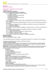
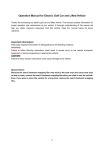
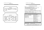
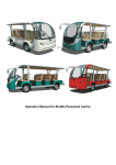
Operation Manual for Electric Utility Vehicle
JH1011 or JHU48-02
1
Thanks for purchasing the products. For better use the product, please read through this
manual; and keep them in the safe place for future reference.
Index
1. Brief Introduction
2. Technical Description
3. Operation System
4. Operational Process
5. Rules of Safe Operation
6. Maintenance
7. Schematic Diagram of the Electrical System
2
1. Brief Introduction
It is a kind of environment-friendly industry vehicle developed by our company used in air
port, sea port, yard, railway station, workshop, etc. Our electric wagon is an ideal off-road
electric vehicle with excellent performance, low noise, pollution-free and new design.
2. Technical Description
Description
Electric Wagon
Car Type
2 seats
Dimensions(mm)
3475x1390x1200
(Length*Width*Height)
Range(km/h)
>80
(smooth and straight road,
20km/h)
Maximum Speed(km/h)
30
Minimum Turning
2.9
Diameter(m)
Maximum Gradeability
20%
(loaded)
110
Min. distance to ground
(mm)
800
Rated loading capacity
(kgs)
3. Operation System
1) Schematic Figure of Operation System
3
2) Functions of Operating System
Power key ---- to master switch of the electric system. When the key being inserted into it
and turned clockwise, it will switch on lights, horn and the control system; when the key
being turned back, the power will be switched off.
Acceleration pedal ---- to control the speed. It should be stepped down slowly. The vehicle
speeds up with the gradual stepping-down, and reaches the full speed when the pedal is
stepped down to the bottom. The vehicle slows down when the pedal being released
gradually. When the pedal is fully released, electric brake works.
Brake pedal —— to decelerate or park the vehicle.
Clutch pedal —— to control the clutch. When driving, do not operate it not completely,
otherwise, it will damage the clutch.
Parking brake controller
—— to park and brake the vehicle.
Steering wheel —— to control the driving direction
Ammeter —— to indicate the current of the working vehicle.
Voltameter—— to indicate the voltage of battery. It ranges from 20V to 60V from left to
right, including 3 sections highlighted by Red, Yellow and Green. Green section
represents the battery is full in capacity. With the consumption of the power, the indicator
will fall from the right to the left gradually. When the indicator comes to the intersection
4
point of the red section and the yellow section, it represents that the battery will come to
the end in capacity, now the battery should be re-charged. When the indicator comes to
the red section, the vehicle is prohibited to use, the battery should be recharged
immediately.
Gearshift —— There is totally 5 positions. Forward shift includes 1,2,3 and 4. Reverse
shift is R. It is recommended to use 1 for climbing, use 2 and 3 for flat road. It is not
recommended to use 4 for driving.
4. Operational Process
1) Switch on the power key;
2) Step the clutch pedal to the bottom, select the right shift and make sure to use right
speed when driving. Selection standard is to make sure that the working current of
motor stays as small as possible as long as this current is enough for driving.
3) Release the brake pedal.
4) Release the clutch pedal slowly.
5) Step down on the acceleration pedal smoothly, in this case, the vehicle starts running.
▼ Warning: If you step down the acceleration pedal before switching on the power key,
the car will not run. In this case, you should release the acceleration pedal first, and step it
down again, thus the vehicle will start running.
5. Rules for Safe Operation
The driver should have a good knowledge of the operation system of the vehicle and its
features, meanwhile follow the rules for safe operation as stated below:
▼ Warning: Drive the vehicle off road unless it is allowed.
z
The vehicle cannot be over-loaded, otherwise the motor will be damaged, the
vehicle will lose control and its life will be shortened.
z
Unqualified persons are prohibited to drive the vehicle.
z
Make sure this vehicle run in its rated climbing ability.
z
Don’t overtake other vehicles at crossroad, in blind area or in other dangerous zone.
6.
Maintenance
5
Users should do maintenance as follows, which will decide the performance of the car and
life of battery:
Maintenance of Battery:
1) The exterior of the battery, the connection wires and bolts should always be kept clean
and dry. If there is any electrolyte, it should be wiped off with clean cotton cloth, then it
should be rinsed by clean water and made dry.
WARNING: During this process, water is prohibited to enter the battery, otherwise, the
battery will be damaged.
2) The battery must be kept in good connection. The tightening nuts for the wiring
connection should be checked frequently to see if any nut becomes loose, otherwise, any
loosing nut will result in sparkle or burnt terminals.
3) Don’t put any article on the battery. And never connect the positive pole to the negative
pole directly, otherwise, it will result in short circuit, and damage the battery.
4) After discharging (in spite of the time it has run and the mileage it has run), the battery
must be recharged on the same day. Never leave the recharging to next day or never
doing the recharging more than 24 hours, otherwise the life of the battery will be impacted.
5) During the use of the battery, the liquid density will increase and the liquid volume
decreases due to the evaporation and electrolysis of water in the electrolyte (it happens
especially in summer), therefore, the battery should be checked periodically and the
electrolyte should be added in time (usually it is only required to add some distilled water).
At the end of recharging, adjust the density of electrolyte to a density of 1.280±0.005(25℃)
by distilled water or dilute sulphuric acid with a density of 1.400 special for lead-acid
battery, in this case, the added liquid cannot exceed the rated volume as specified on the
battery. After this adjustment, the battery should be kept on charging for 0.5 hour to 1 hour
to make the electrolyte become uniform everywhere.
6) No foreign articles are allowed to enter inside the battery. Keep the watering
instruments clean to prevent any foreign articles from entering the battery.
7) When driving, the driver shall keep an eye on the indicator of batter power (once the
indicator of voltmeter comes to the red section, this vehicle should be stopped
immediately and the battery should be recharged). Besides, the driver shall estimate the
mileage left to guarantee that the battery has enough power to make this vehicle return to
be recharged, otherwise, the battery will be over-discharged, and its life will be shortened
greatly.
8) If the vehicle is out of use for long time, the battery shall be fully recharged before being
stored, after that, the battery should be fully recharged once every 0.5 month until the
charger switches off automatically.
9) During recharging the battery, the vehicle shall be parked in a ventilating place with the
battery cover open to avoid any accident.
10) After recharging, close the battery cover and check whether there is any jam in the
outlet, if any, remove that.
11) The life of a lead-acid battery is over one year. Toward the end of its life, the battery
capacity will shrink dramatically, in this case, a new battery should be used. Only battery
6
in same brand, same capacity and same voltage can be used as a group for the
replacement.
12) Recharge the battery once each month to make the electrolyte uniform.
Instructions and Notes for the Use of the Charger:
An automation-oriented design and easy operation
① Connect the power plug to a power of 110V ~ 60Hz.
② Connect the output plug to the battery.
③ When above procedures have been finished, the POWER light turns on, which
indicates that the output and input are in good connection. When battery is being
charged, the WORK Light turns on, which indicates that the power output is okay, and
the charger starts working.
④ Some notes during the charging process:
There are three indicators of
showing how much has been
charged, and the charger will power off after the battery has been fully charged.
⑤
⑥
⑦
⑧
⑨
The charger case is prohibited to be opened during charging.
Non-servicemen are not allowed to open the charger’s box.
The charger should be placed in safe and dry atmosphere with good ventilation.
The charger should be packed for storage in case of no use for long time.
During charging, the charger will switch off automatically as self-protection once the
voltage does not stay within 90V-120V, meanwhile the alarm light will switch on to
remind the user. The charger will recover once the voltage comes to the range of
90V-120V.
Maintenance of the Transmission Case:
① The clearance for the clutch should be kept between 2-3mm.
② The friction plate should be changed periodically, the friction value on one side should
not exceed 2mm.
③ Adjust the flatness of the platen spring plate (feeling manually): first tighten the screws
diagonally, use your hand to check the flatness of the spring plate. If not flat, tighten
the screws for the non-flat part.
④ Change the gear oil periodically (half year) inside the transmission case, the kerogen
is 85W/90GL.
WARNING: Never mix different oils.
Maintenance of the Traction Motor
⑤ This traction motor is designed to use at the sea level not beyond 1200 meters and in
a temperature between -25℃ and 40℃.
⑥ This motor can work properly with a voltage between 32V and 54V produced by
7
battery in series.
⑦ Never keep the motor running idly.
⑧ No explosive gas shall exist in the air.
⑨ Any mud, sand and other clinging objects shall often be cleaned away so as to provide
good heat-radiation.
Trouble-Shooting for Motor:
Series Symptoms
Possible Causes
A
All copper plates turn black.
The pressure of brush is incorrect.
B
The commutators turn black
short circuit inner commutators or on the
in a certain order and in
armature coil; poor welding or disconnection
groups.
between the commutators and the armature coil.
The commutators turn black
The central line of the commutator deviates or its
in disorder.
surface is not round and not smooth.
The brush wears out, turns
The motor vibrates; the clearance between the
colors and become broken.
brush and its holder is too big; the clearance
C
D
between the brush and commutators is too big;
the
mica
between
different
commutators
extrudes; the brush is made by wrong materials;
the brush is wrong in type.
E
Big sparkles
The motor is over-loaded; the commutators are
not clean, not round or not smooth; mica orsome
commutators extrude; the brush is not ground
properly; the brush is big in pressure; the brush is
wrong in type; the brush is jammed in the brush
holder; the brush holder become loose or
vibrating; the polarity and sequence of magnetic
poles become wrong.
F
The brush and its wires get
big sparkles of the brush; poor contact between
hot.
brush and soft wires;. small section area of soft
wires.
8
g
The brush is noisy
The surface of the commutators is not smooth.
Maintenance of the Speed Controller
The speed controller of the car is wholly imported, which adopts high frequency MOS
technology to realize the speed, torque and brake control with smoothness, silence, high
efficiency and energy-save.
① Periodical Maintenance:
a. Check if the contact between contacting point of the contactor is in good condition,
check if any contact sticks or is jammed mechanically.
b. Check if the micro switch in the accelerator can be switched on and off properly.
c. Check if the switch for turn signal can be switched on and off properly.
c. Check if all the connections between the motor, the battery, and the controller are in
good condition.
NOTES: all above checks shall be performed under power off. Above checks shall be
carried out once every 3 months; after the power key turns off, the wave-filter capacitor in
the controller unit shall keep discharging for a few minutes more; don’t wash the electrical
parts with water. It is allowed to remove dust with a brush or high–pressure air.
② Trouble-Shooting Guide:
Symptoms
Possible Causes
The vehicle cannot be A. The controller has no power;
started.
a. There is something wrong with the battery or wire
connections.
b、the fuse of power connection is burnt;
c、the resistance for pre-charging is broken.
B. No signal is transmitted to the controller:
a. The power key is damaged or its wiring become
disconnected.
b. The accelerator of the pedal is damaged.
c. There is something wrong with acceleration pedal
d. The polarity diode is broken or has short cut.
d. The green wire connecting the acceleration pedal and
the controller KSI is disconnected;
C. The contacting point of the contactor becomes stick.
D. The controller of the motor is damaged.
The vehicle can only A. The switch is damaged.
move forward and cannot B. The inserts on the commutators become loose.
be reversed, or vice versa C. The commutators are damaged.
9
Brake System
① step down the brake pedal with a force of 30kg or so, keeping the vehicle moving not
more than 2/3 of its rated range.
②The clearance for the brake plate is self-adjusted. Under a force of around 20kgs, the
parking brake handle should be fixed in one gear from 5 to 10 ratchet. When this brake
handle is released completely, the brake function will stop.
Lubrication and Maintenance of the Whole Car
①
Use 901 car brake oil DOT3 as brake oil;
②
③
④
Use 1L of 85W/90GL lubrication oil for transmission case;
Use 1L of 90GL hypoid gear oil for the rear axle;
Lubrication points: a. steering gears; b. horizontal bars; c. steering ball joints; d.
bearings;
Running-in of New Vehicle:
In order to guarantee the performance of the vehicle and enhance its reliability and
working lift, all parts in motor should experience a certain period of running-in before the
motor works with its maximum capacity, thus, each new vehicle is required to give one
month of running-in time, detail procedure as per the following:
① Check the levels of oil, water and liquids carefully before running-in and fill them as
requested if insufficient; The tire should meet 145/80R12 with the air pressure of
5.5kgf/cm2.
② During running-in time, the speed should be limited as follows:
Current
Shift
1
2
3
4
100A
50A
50A
55A
Model
EG1011
③ If possible , try your best to avoid driving on roads in poor conditions.
④ Check and tighten regularly the fixing parts of each connecting points.
Notes:
10
① Front parking brake should be released to its bottom to avoid any damage on the
brake plate.
② The lubricant for rear power assembly must be applied and changed as per user’s
manual.
③ The brake system must be adjusted once every 3 months.
④ The electricity system must be checked once every 3 months (especially main circuit)
for its fastening parts and wiring connections. Meanwhile the contactor should be
checked, any defective parts should be replaced immediately. Its dust should be
cleaned by low pressure air.
⑤ The electric contactors easily become hot if their mutual contact is not in good
condition, so special attention should be paid regularly to the electric contactors.
⑥ When changing the fuse, make sure that the new fuse is right in rated current.
⑦ For the sake of safety, disconnect the positive pole from the battery when
maintenance is done.
⑧ Never step the accelerator hard and frequently, which may shorten the life of the
controller.
⑨ It is prohibited to fill any other liquids (such as battery addictives, mineral water and
tap water) into the battery, ONLY the distilled water is allowed to fill in the battery.
⑩ Do not drive at high speed when going downhill; slow down the car when turning; and
remind the passengers to hold on when turning and going downhill.
⑾ Children are not allowed to play in the car; children should be seated between adults
and cared by adults when the car is running.
This manual tries to be as sound and elaborate as possible in literal and figurative description as
well as technical description on the basis of existent data. At the same time, our company reserves
the right to alter the content of this manual and this manual is subject to change without prior
notice; in addition, our company has the final say on the interpretation of this manual.
All rights reserved.
First Impression, March 2003; First Edition, 2003
Products are not in our warranty.
11