1
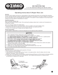
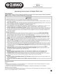
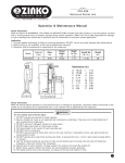
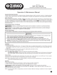
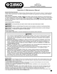
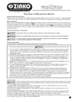
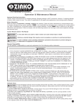
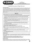
MODEL
ZML-800 (800 lbs)
Telescopic Transmission Jack
Toll Free: 1-800-579-8088 Web: www.zinko.com
Operation & Maintenance Manual
Important Receiving Instructions
Visually inspect all components for shipping damage. Shipping damage is NOT covered by warranty. If shipping damage
is found, notify carrier at once. The carrier is responsible for all repairs and replacement costs during product shipping.
For Your Safety and To Prevent Injury
Read, study and understand all warning labels and operating instructions furnished with this equipment prior to use. If
any portion of this material is unclear, contact your representative for clarification. Never allow unskilled or improperly
trained personnel to operate this equipment. Use of the transmission jack is limited to the removal and installation of
transmissions, transaxles and vehicle components for which appropriate adapters are supplied. DO NOT lift or support
vehicles with transmission jack.
Caution Remarks Used In This Manual
indicates a potential danger that requires correct procedures or practices to avoid personal injury.
Operator Responsibility
It is the operator's responsibility to read and understand all of the following safety statements:
1.
2.
3.
4.
5.
6.
7.
8.
Be sure vehicle is appropriately supported before starting repairs. This jack IS NOT a load supporting device.
DO NOT OVERLOAD. Overloading can cause damage, failure of the jack, and/or personal or fatal injury.
Use only on hard level surfaces capable of sustaining the load.
Always use the load restraint belt, corner support bracket, and attachments to stabilize and firmly secure the
load to the saddle. Insure that the load restraint belt is tight and properly positioned to effectively harness the
load. NEVER USE THIS JACK WITHOUT A LOAD RESTRAINT BELT THAT IS STRONG ENOUGH TO SUPPORT
THE TRANSMISSION.
Prior to transporting the load, insure that the jack is adjusted so the saddle is in the lowest horizontal position
possible, and the load is centrally located on the saddle.
DO NOT modify this equipment or remove load restraint belt.
It is your responsibility to keep all warning labels and instruction literature legible and intact. Replacement labels
and literature are available from the factory.
Failure to heed these warnings may result in equipment and/or property damage and/or personal or fatal injury.
Purging Air From the Jack
The jack may become "air-bound" during shipment. You may experience the air-bound condition if the hydraulic unit
does not function properly during the pumping operation. To purge air from the jack, follow these steps:
1. Make sure the rams are in a retracted position.
2. Have one person depress the release pedal while at the same time another person activates the pump foot pedal
about 20 times.
3. Remove your foot from the release pedal and the jack should function properly. NOTE: Sometimes air may be trapped
in the top cylinder which requires bleeding air out of the air bleeder screw in the top cylinder nut. Pump the jack to
maximum extension or as high as you can pump it. Insert an allen wrench in the air bleeder screw located in the top
cylinder nut and loosen the screw slowly while pushing the saddle assembly down. Continue opening the screw
slowly until nothing but oil drains out of the hole. Tighten the screw and operate normally. It may be necessary to
repeat this step several times.
Operating Instructions
Preparing the Vehicle for Transmission Removal or Installation
The entire vehicle must be lifted and supported (use under-hoist stands) high enough above the floor
so there is space for the jack with transmission to clear the vehicle.
IMPORTANT: It is important to know the center weight balance of the transmission. The transmission saddle should
support the center balance of transmission weight. Consult the vehicle manufacturer for information on the transmission.
USE ALL THE PRECAUTIONARY MEASURES GIVEN BY THE ABOVE GROUND LIFT MANUFACTURER
TO SECURE, SUPPORT, AND LIFT THE VEHICLE TO ITS REQUIRED HEIGHT.
Zinko Hydraulic Jack
Model: ZML-800 Operating Instructions (continued)
Lowering the Load
To lower the jack, simply depress the desired pedal slowly. The saddle stops lowering when the operator removes foot
from the release pedal.
1. DO NOT use the jack beyond its rated capacity or for purposes other than what were intended.
2. The jack and load may be lowered by depressing the release pedal with your foot. Light depression of the release
pedal lowers the jack slowly. Be careful not to fully depress the release pedal when the jack is under load. Operate
the release pedal without load on the jack to familiarize yourself with the control of speed to lower the jack.
Always use the proper release pedal for lowering the jack. Using the small pedal incorrectly when the
jack is loaded may result in equipment and/or property damage and/or personal or fatal injury.
Raising the Load
1. Make sure the load to be raised is positioned properly and securely
attached to the saddle assembly with the restraint system provided.
2. Pump pedal to raise saddle to contact load. Position jack so weight of
load will be equally distributed on saddle, and adjust pitch and tilt controls
as necessary. Position corner support brackets and secure load with load
restraint belt. Make sure the load to be raised is positioned properly and
securely attached to the saddle with the restraint system provided.
Always use the load restraint belt, corner support brackets,
and attachments to stabilize and firmly secure the load to the
saddle. The belt should be used as follows: Hang the open end of the belt through
the two "U" shaped slots beneath the saddle plate. Place the belt over the load, pull
tight and engage into the buckle at the other end of the belt. Tighten the strapping and
lock the buckle.
TILT ADJ. KNOBS
Removing the Transmission
1. Consult the vehicle manufacturer's instructions regarding transmission removal.
2. Place the jack so the saddle assembly will lift the center balance of the transmission weight. Pump the jack up until
the saddle is close to the transmission oil pan.
3. Once the saddle is centered and positioned near the transmission oil pan, adjust the saddle base and corner support
brackets (adapters) so the flange of the transmission pan will rest on the top edge of the adapters. The adapters must
then be secured to the saddle by tightening the hex bolts. Now gently raise the saddle so the adapters are supporting
the transmission pan flanges.
4. Use the load restraint belt, corner support brackets, and attachments to stabilize and firmly secure the load to the
saddle.
5. Use the saddle plate tilt knobs, forward/backward or side-to-side tilting, to adjust the load to a proper position for
transmission removal or for alignment with the engine.
Installing the Transmission
1. After removal of the transmission it is recommended to keep the transmission jack saddle adjustment the same.
This will help in installing the transmission into its proper position.
2. Proceed with the installation of the transmission in accordance with the vehicle manufacturer's instructions.
Maintenance Instructions
1. Lube the jack regularly. A medium weight lubricating grease should be used on all external moving parts, such as
bearing surface, pivot points, tilt screws, etc.
2. Regularly check oil level. With the saddle fully lowered, remove oil plug and check oil level. Fill if necessary.
3. If jack fails to operate, check oil level and/or bleed unit before seeking service.
4. DO NOT use this jack as a wash rack when washing or steam cleaning transmissions.
Zinko Hydraulic Jack
Model: ZML-800 Parts Breakdown
Pump Unit
Pump Unit
Part #
9140008-P1
9140008-P2
9140008-P3
9140008-P4
9140008-P5
9140008-P6
9140008-P7
9140008-P8
9140008-P9
9140008-P10
9140008-P11
9140008-P12
9140008-P13
9140008-P14
9140008-P15
9140008-P16
Description
Pump Body
Valve
Ball
Stop Ring
Pump Plunger
*O-Ring
*O-Ring
*Backup Ring
Piston
Pin
Pin
Pin
Spring
Piston Case
Pin
Pin
Part #
9140008-P17
9140008-P18
9140008-P19
9140008-P20
9140008-P21
9140008-P22
9140008-P23
9140008-P24
9140008-P25
9140008-P26
9140008-P27
9140008-P28
9140008-P29
9140008-P30
9140008-P31
9140008-P32
Description
Hydraulic Pipe
Nipple
Nipple
Nipple
Spring
Stop Pin
Ball
Hydraulic Pipe
Socket Ball
Socket Ball
Safety Valve
*O-Ring
Stop Nut
Spring
Safety Valve
Ball
Part #
Description
9140008-P33 Pin
9140008-P34 Spring
9140008-P35 Spring Hanger
9140008-P36 Backup Ring
9140008-P37 Nut
9140008-P38 *O-Ring
9140008-P39 Pin
9140008-P40 Down Pedal
9140008-P41 Washer
9140008-P42 Pedal Assy
9140008-P-A Piston Assy
9140008-P-B Piston Packing Seat
9140008-P-C Pressure Valve Set
9140008-P SK Seal Kits
* Included in Seal Kits
Zinko Hydraulic Jack
Model: ZML-800 Parts Breakdown
Frame Unit
Frame Unit
Part #
9140008-PU
9140008-1
9140008-2
9140008-3
9140008-4
9140008-5
9140008-6
9140008-7
9140008-8
9140008-9
9140008-10
Description
Pump Unit Assy
Cylinder Body Assy
Oil Tank
*O-Ring
Nut
*O-Ring
Nut
*O-Ring
*O-Ring
Air Valve
Cylinder
Part #
9140008-11
9140008-12
9140008-13
9140008-14
9140008-15
9140008-16
9140008-17
9140008-18
9140008-19
9140008-20
9140008-21
Description
Main Piston
Cylinder Piston
*Tape O-Ring
*Backup Ring
*O-Ring
*Tape O-Ring
*Backup Ring
*O-Ring
*Stop Ring
Legs
Nut
(909)989-9526
(909)989-1724
Part #
Description
9140008-22 Washer
9140008-23 Screw
9140008-24 Screw
9140008-25 Nut
9140008-26 Wheels
9140008-27 Screw
9140008-28 Grip
9140008-29 Case
9140008-SK Seal Kits
* Included in Seal Kits